

Page 1
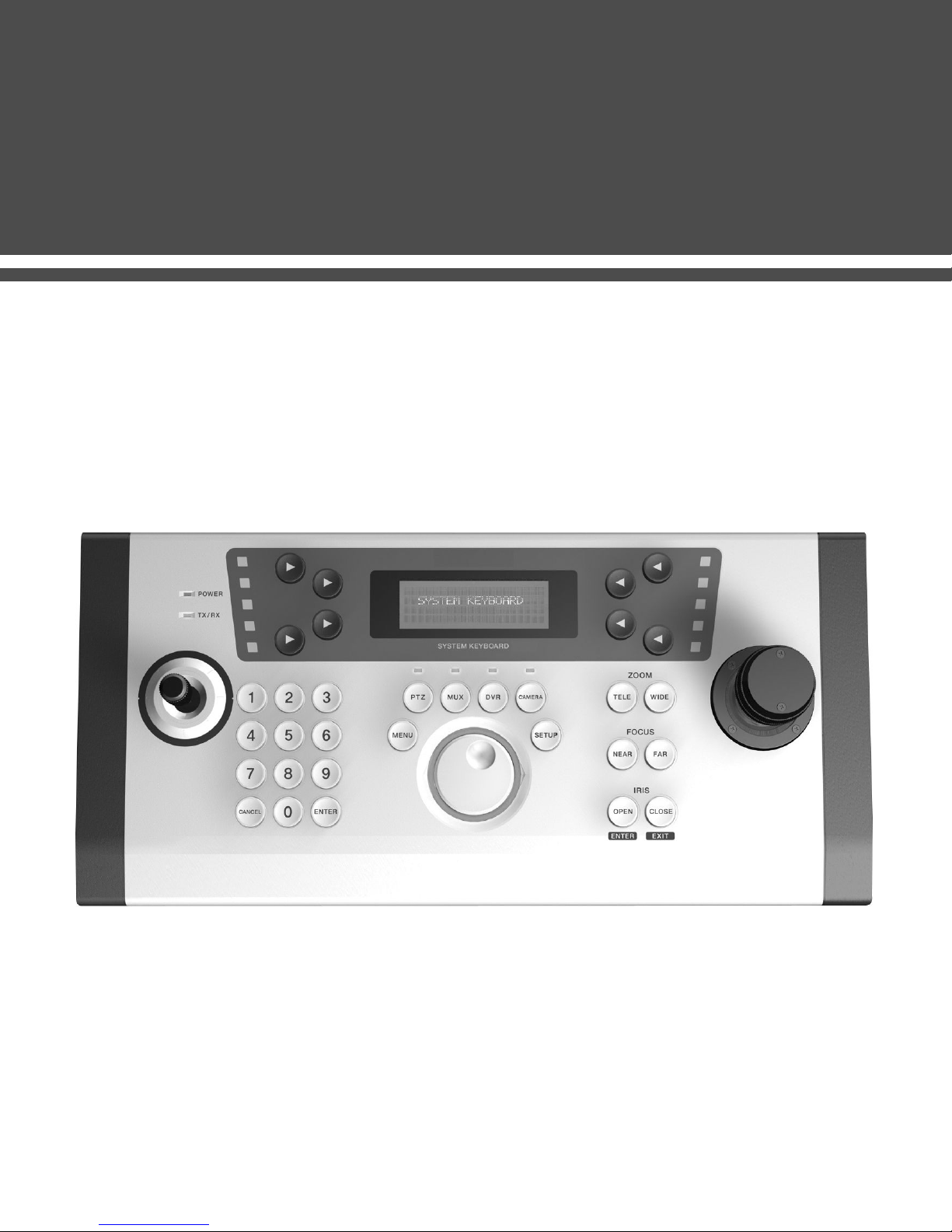
SYSTEM CONTROLLER
USER MANUAL
Page 2
If the product is to be put out of operation definitively, take it to a local
recycling plant for a disposal which is not harmful to the environment.
Please read the instructions carefully for correct use of the product and preserve it for
reference purposes. This specification is subject to change without any prior notice to
improve the quality.
Page 3

Contents
Warning and Cautions
................................................................................................
<Chapter 1. Major functions and Features>
1.1 Overview
1.2 Features
1.3 Names and functions of each part
...............................................................................................................
...............................................................................................................
.........................................................................
<Chapter 2. How to install >
2.1 Environment for installation
2.2 Safety caution
2.3 Product components
.......................................................................................................
.....................................................................................
...........................................................................................
5
6
6
6
9
9
10
<Chapter 3. System Connections>
3.1 Connecting Junction Box and External Devices
1) Connecting with PTZ camera
2) Connecting with DVR
3) Connecting with MUX
3.2 Connecting two or more controllers
3.3 General Connection
1) One keyboard to one device
2) One keyboard to multiple device
3) Multiple keyboards to multiple devices
....................................................................................................
...................................................................................................
.............................................................................................
........................................................................................
.......................................................................
........................................................................................
..................................................................................
.........................................................................
<Chapter 4. How to use>
4.1 Log In
.................................................................................................................
.....................................................
10
10
12
12
13
14
14
14
15
16
1) How to log in
2) How to set Password
.................................................................................................................
....................................................................................................
16
16
3
Page 4

Contents
4.2 Infomation
4.3 Control PTZ
1) Select PTZ
2) Camera Setting
3) Preset
4) Auto Pan Mode
5) Scan Pan Mode
6) Pattern
7) AUX Mode
8) Pattern Stop
9) Group Mode
10) Tour Mode
4.4 Control DVR
1) Control DVR Mode
...........................................................................................................
..........................................................................................................................
.........................................................................................................................
.........................................................................................................
....................................................................................................................
.............................................................................................................
............................................................................................................
..........................................................................................................
...................................................................................................................
.................................................................................................................
................................................................................................................
..................................................................................................................
.......................................................................................................
.......................................................................................................
18
19
19
21
23
26
28
30
34
35
36
39
40
40
2) DVR Setup
....................................................................................................................
<Chapter 5. Specification>
Specification
.............................................................................................................
<Chapter 6. Q&A>
Q&A
........................................................................................................................
41
42
43
4
Page 5
1. Warning and Cautions
Please carefully check these particulars for the safe use.
2. Examples of sign
Warning and Cautions
WARNING
CAUTION
to the user.
This symbol indicates the cause of equipment damage.
WARNING
1. Use the AC adaptor 12V DC, 300mA regulated.
2. Do not connect one adaptor with more than one controller.(It may result in fire, malfunction.)
3. Be sure to connect power cable securely.
4. Do not place metalic objects on the controller.
5. Never expose the appliance to moisture or dust.(It may result in fire.)
6. Immediately turn the power off to the appliance if there is any abnormal condition such as
smoke or unsual smells.(Continuing to the appliance under abnormal conditions may result in
serious damage.)
7. Do not attempt to disassmble the appliance. If it doesn't work, contact qualified service personnel
for maintenance. (In case any problem occur by disassembling the appliance, we assume no
responsibility or liability.)
8. Do not get the appliance wet.(It may result in fire or electric shock.)
If the body get dirty, wipe the surface with a soft cloth.
This symbol indicates the cause of death or serious injury
1. Do not drop the appliance on the floor and avoid from vibration or magnetic objects.
2. Always operate the appliance within the recommended temperature range of -10℃ ~ 50℃.
3. If you want to move the appliance, please turn the power off and re-install the appliance.
4. Install the appliance in places where there are well ventilated.
5. If there are thunder or lighting, please turn the power off.
CAUTION
5
Page 6
Chapter 1. Major functions and Features
Chapter 1. Major functions and Features
1.1 Overview
This product is designed to control PTZ CAMERA, DVR and other equipment by RS-485 or
RS-422
1.2 Features
1) A long distance remote control
It is possible to control equipment at a distance of 1.2Km by using RS-485.
2) System Control
Camera(Receiver Unit) and DVR are controllable by one controller.
3) Multi-controller connection
Multi-connection enables users to control equipment at a separate place.
4) LCD display
LCD shows MENU, the status of operation, and other information to control easily.
1.3 Names and functions of each part
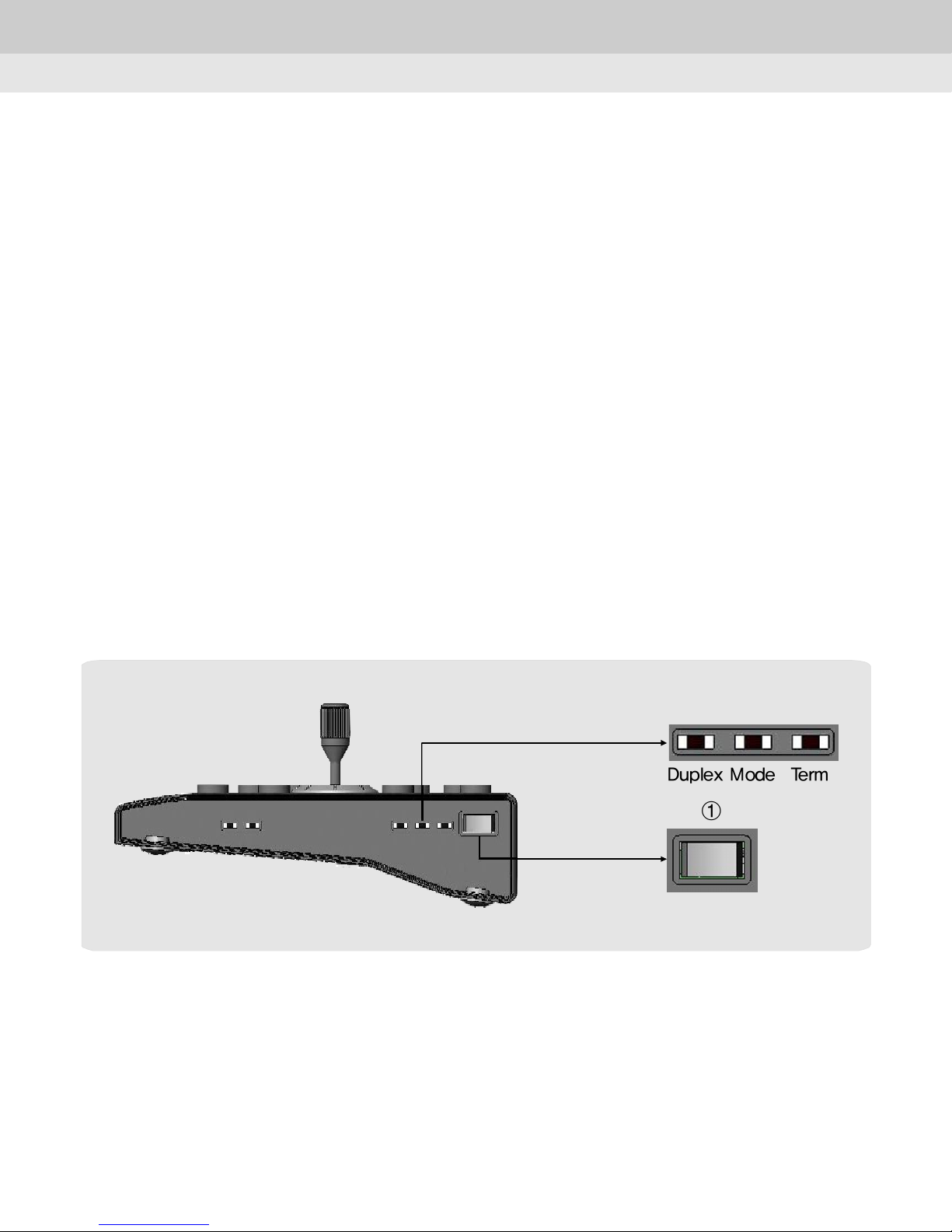
② ③ ④
Duplex Mode Term
①
Power
①Power switch :
ON/OFF
②Communication method selection :
③Mode selection :
④Termination selection :
ON : Set on the last controller for 1:1 or multi communication.
OFF : Set on all controllers except for the last controller for multi communication.
Master / Slave
RS-422: Full Duplex, RS-485: Half Duplex)
6
Page 7
Chapter 1. Major functions and Features
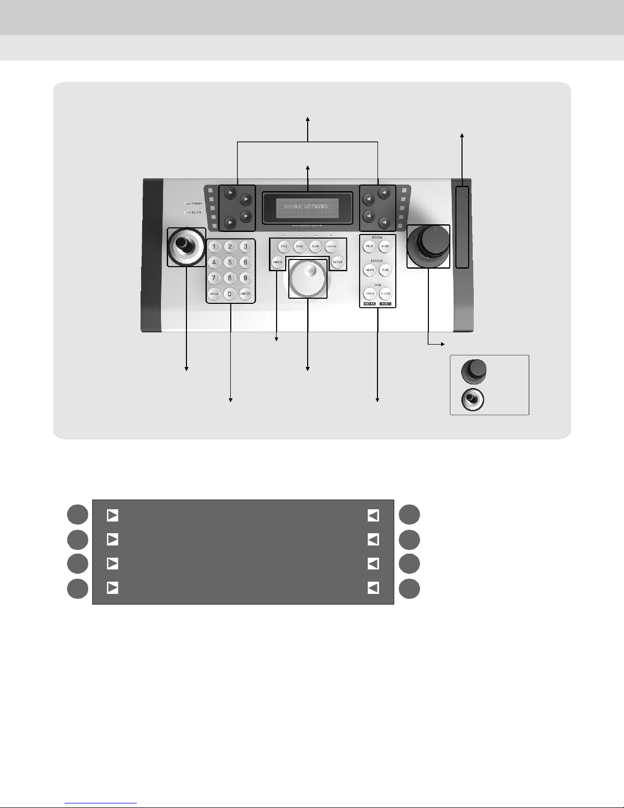
②Function
①LCD
⑨Power
①LCD Display :
②Function Key :
F1
SUNKWANG CA M:00 1
F2
F3
F4
③JOG Dial :
Used for easy control.
⑧Mode
④Sub Joystick
⑦Number, Enter, Cancel ⑥Zoom, Focus, Iris
③Jog
Shows the information related to the operation.
There are 8 buttons(F1 ~ F8) to select functions.
Preset
AutoPan
Sc anPan
[
[ ][ ]
[[
[[
Pattern
Aux
Stop
]
]]
]]
⑤Main Joystick
Type 1
2Type
F5
F6
F7
F8
④Sub JoyStick :
⑤Main JoyStick :
Used for DVR MENU selection or movement by specific direction.
Used for Pan/Tilt control or special functions.
⑥Zoom / Focus / Iris Key :
Zoom :
ㆍ
Focus :
ㆍ
Iris :
ㆍ
Performs camera zoom action(wide and telephoto).
Used for manual focus adjustment.
Adjusts the brightness or selects OSD menu of the camera.
7
Page 8
Chapter 1. Major functions and Features
⑦Number / Enter / Cancel Key
: Enter the numeric values for PTZ or DVR menu setting.
⑧Mode Key :
ㆍPTZ :
ㆍMUX :
ㆍDVR :
ㆍCAMERA :
ㆍSETUP :
ㆍMENU :
⑨Power :
Selects PTZ mode.
Selects Mux mode.(It will be available in the future.)
Selects DVR mode.(Available with the designated DVR)
Selects CAMERA mode except PTZ camera.(It will be available in the future.)
Sets the basic setting.
Menu display.
Power and switches.
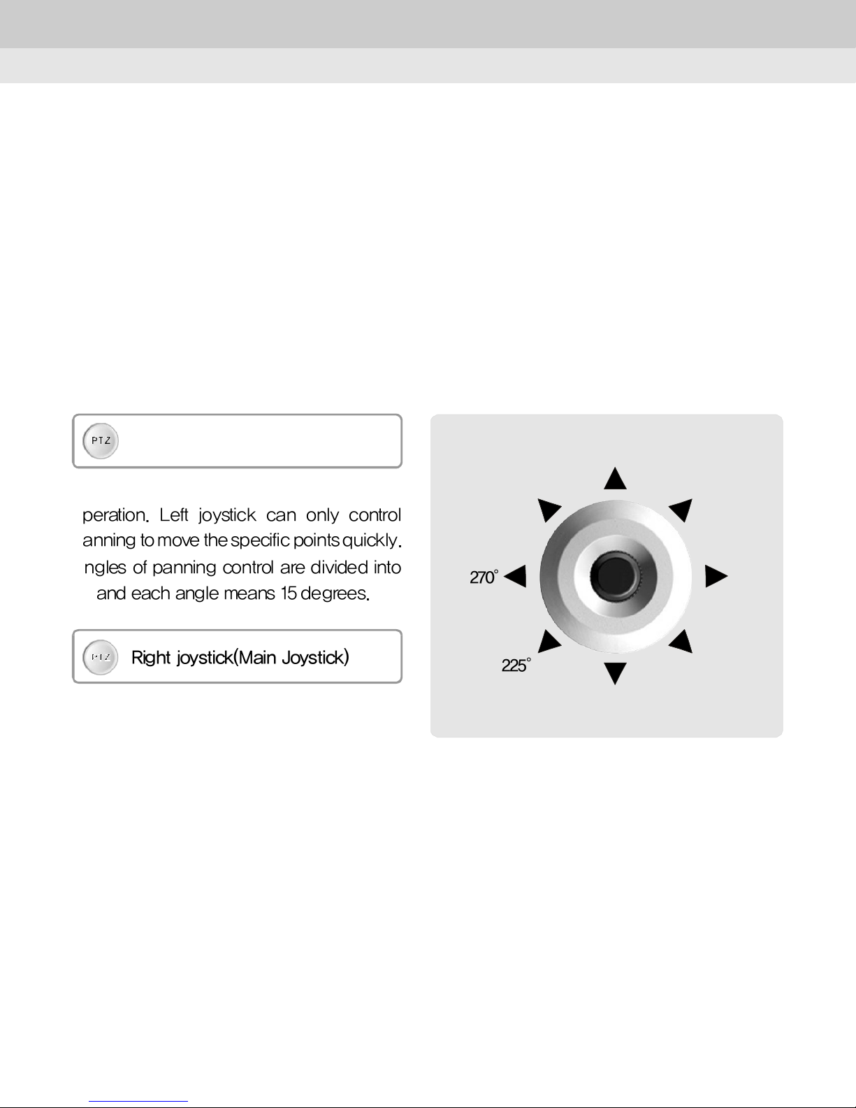
<Basic joystick control>
PT Z
Left joystick(Sub Joystick)
This controller adopts two joystick for easy
operation. Left joystick can only control
0°
45°315°
panning to move the specific points quickly.
Angles of panning control are divided into
24 and each angle means 15 degrees.
PT Z
Right joystick(Main Joystick)
Right joystick is for paning and tiltingcontrol.
Press 'PTZ' button to control panning and
tilting.
Refer to "Chapter4" for additional functions.
270° 90°
225° 135°
180°
8
Page 9
Chapter 2. How to install
Chapter 2. How to install
2.1 Environment for installation
1) Please read carefull to install the appliance with safety.
2) Please install the product on a completely flat floor or table.
3) Install the appliance in places where there are well ventilated.
4) It is strongly recommended to install the controller at environment as follow.
- Operation Temp. : -10℃ ~ 50℃
- Preserve Temp. : -20℃ ~ 60℃
- Operation Humidity : 20% ~ 85%
- Preserve Humidity : 20% ~ 95%
- Power supply : 12V DC , 300mA
2.2 Safety caution
1) Be sure to turn the power off before installation.
2) Strong shock or vibration may result in abnormal operation.
3) Do not install the product in the place where there are strong magnetic objects such as
radio or TV.
4) Keep the place where the product is installed clean.
5) Install the product more than 15cm away from the wall.
6) Do not place the appliance in direct sunlight.
7) Immediately turn the power off to the appliance if there is any abnormal condition such as
smoke or unusual smells.
If the controller body gets dirty, wipe the surface with a soft cloth. Do not use chemical
agents such as alcohol or benzene.
CAUTION
9
Page 10
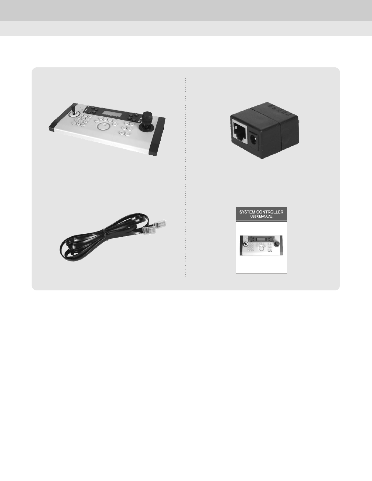
2 3 Product Components.
Chapter 2. How to install
Controller
Cable
Junction Box
Manual
10
Page 11
Chapter 3. System Connections
Chapter 3. System Connections
This chapter describes how to connect the controller with cameras, DVRs, multiplexers and
other devices.
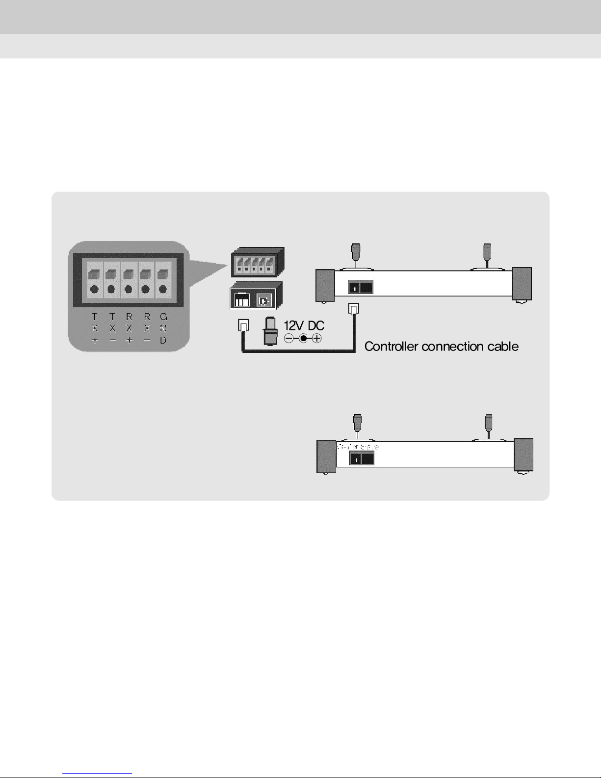
3.1 Connecting junction box and external device
<Front>
T
T
X
X
+
-
R
R
X
+
G
X
N
-
D
12V DC
Controller connection cable
Junction Box
<Back>
Master
Slave
1) Connecting with PTZ camera
Connect TX+ and TX- terminals to the unit as the above picture.
①In case of connection for Half Duplex(RS-485)
- Connect RX(+)terminal on PTZ cameras to TX(+)terminal on the junction box.
- Connect RX(-)terminal on PTZ cameras to TX(-)terminal on the junction box.
②Connection for Full Duplex(RS-422)
- Connect RX(+) terminal on PTZ cameras to TX(+) terminal on the junction box.
- Connect RX(-) terminal on PTZ cameras to TX(-) terminal on the junction box.
- Connect TX(+) terminal on PTZ cameras to RX(+) terminal on the junction box.
- Connect TX(-) terminal on PTZ cameras to RX(-) terminal on the junction box.
11
Page 12
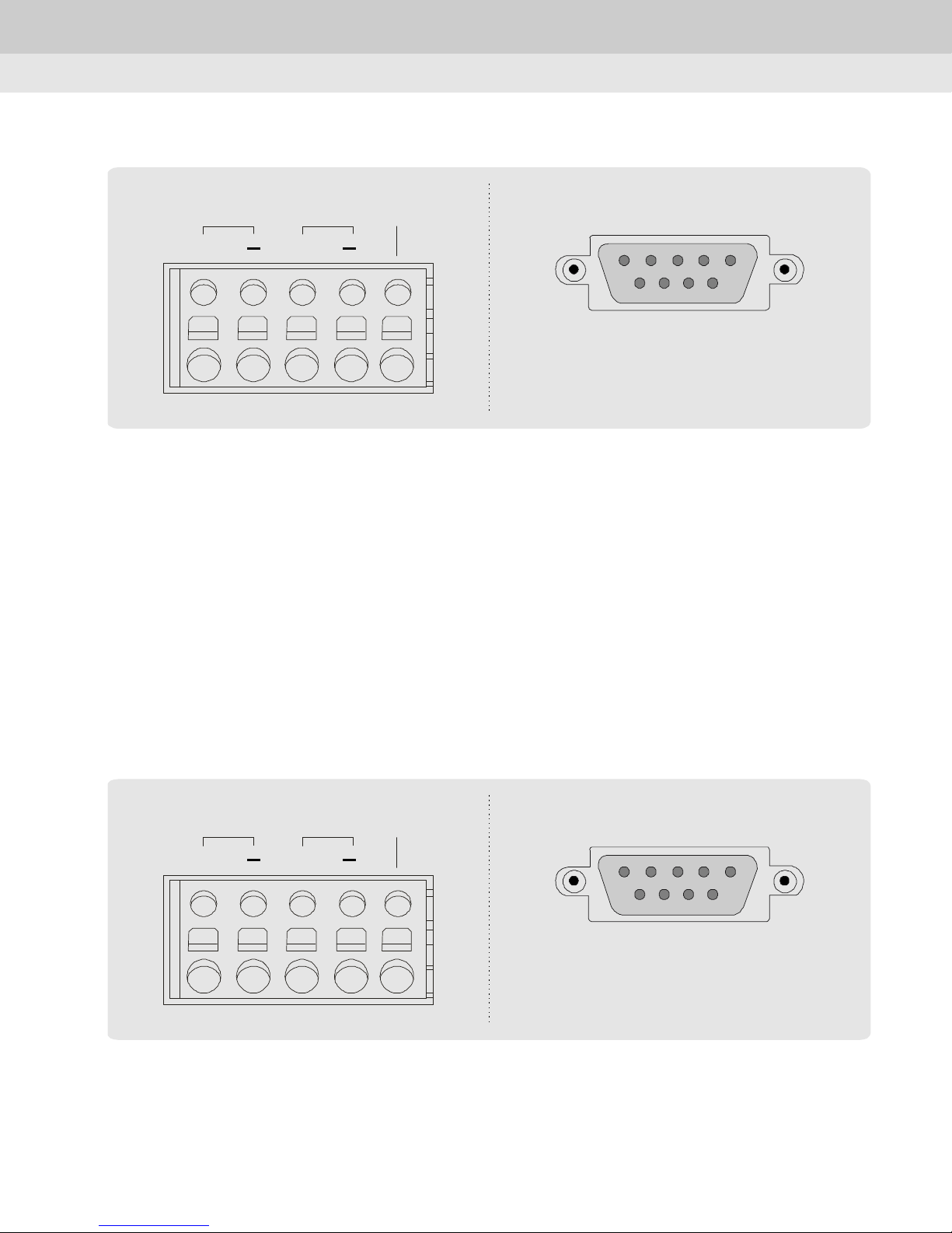
2) Connecting with DVR
Chapter 3. System Connections
TX RX
+
+
GND
Connect RS-485 converter
to serial port of DVR(as above).
①Connection for Half Duplex
- Connect TX(+) terminal on RS-485 converter to TX(+) terminal on the junction box.
- Connect TX(-) terminal on RS-485 converter to TX(-) terminal on the junction box.
②Connection for Full Duplex
- Connect TX(+) terminal on RS-422 converter to TX(+) terminal on the junction box.
- Connect TX(-) terminal on RS-422 converter to TX(-) terminal on the junction box.
- Connect RX(+) terminal on RS-422 converter to RX(+) terminal on the junction box.
- Connect RX(-) terminal on RS-422 converter to RX(-) terminal on the junction box.
3) Connecting with MUX
TX RX
+
+
①Connection for Half Duplex
- Connect TX(+) terminal on RS-485 converter to TX(+) terminal on the junction box.
- Connect TX(-) terminal on RS-485 converter to TX(-) terminal on the junction box.
GND
Connect RS-485 converter
to serial port of DVR(as above).
12
Page 13
Chapter 3. System Connections
②Connection for Full Duplex
- Connect TX(+) terminal on RS-422 converter to TX(+) terminal on the junction box.
- Connect TX(-) terminal on RS-422 converter to TX(-) terminal on the junction box.
- Connect RX(+) terminal on RS-422 converter to RX(+) terminal on the junction box.
- Connect RX(-) terminal on RS-422 converter to RX(-) terminal on the junction box.
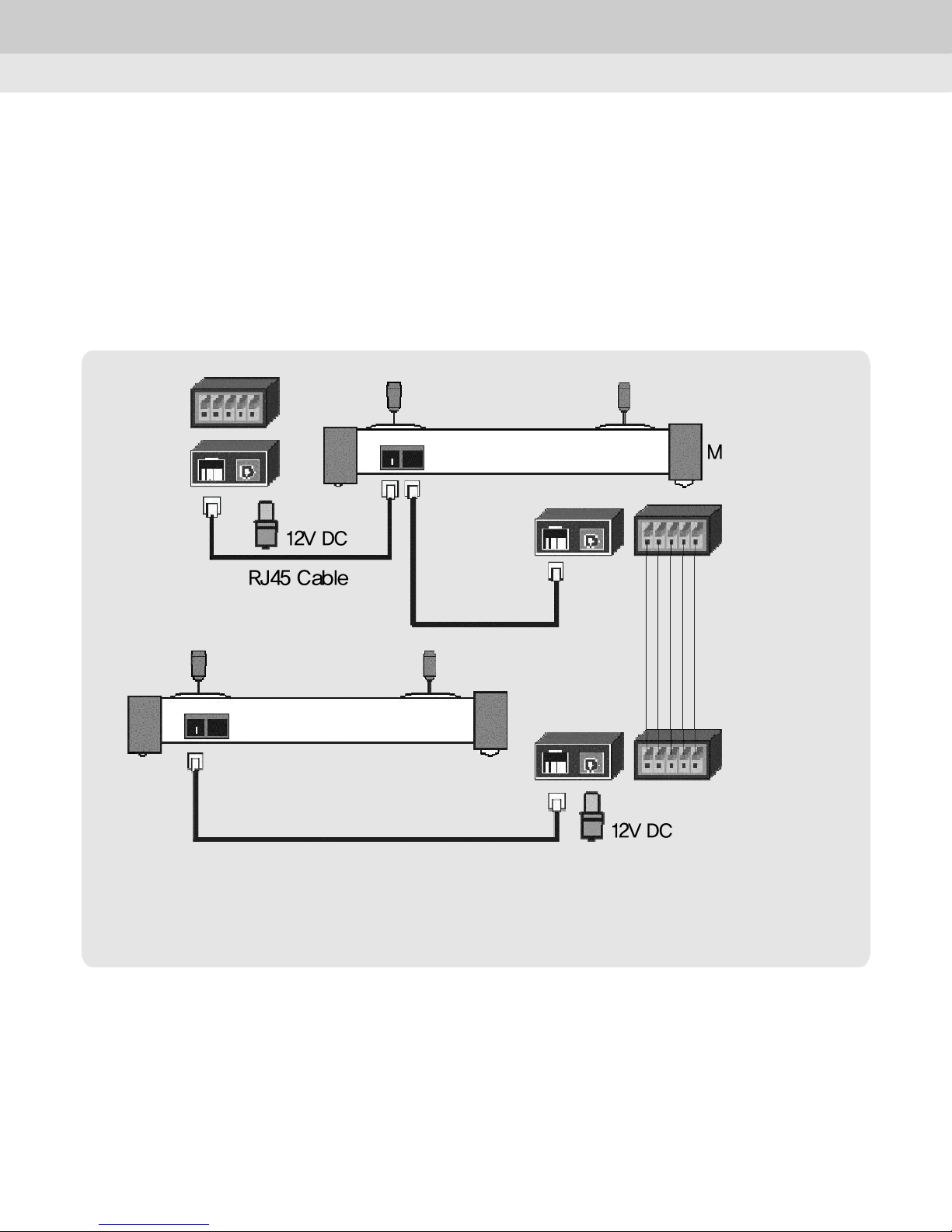
3.2 Connecting two or more controllers
Master
12V DC
RJ45 Cable
Communication
Wire
Slave
12V DC
①Connection for Half Duplex(RS-485)
- Connect TX(+) terminal on the junction box of the master controller to TX(+) terminal on
the junction box of the slave controller.
- Connect TX(-) terminal on the junction box of the master controller to TX(-) terminal on
the junction box of the slave controller.
13
Page 14
Chapter 3. System Connections
②Connection for Full Duplex
- Connect TX(+) terminal on the junction box of the master controller to TX(+) terminal on
the junction box of the slave controller.
- Connect TX(-) terminal on the junction box of the master controller to TX(-) terminal on
the junction box of the slave controller.
- Connect RX(+) terminal on the junction box of the master controller to RX(+) terminal
on the junction box of the slave controller.
- Connect RX(-) terminal on the junction box of the master controller to RX(-) terminal
on the junction box of the slave controller.
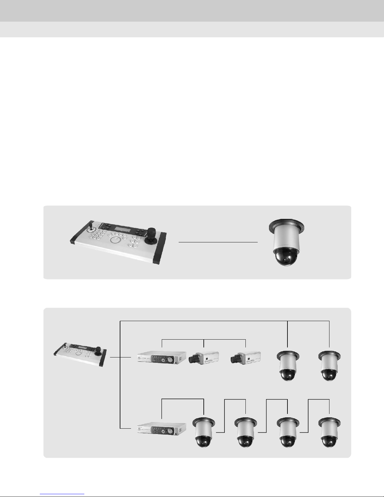
3.3 General Connection
1) One keyboard to one device
2) One keyboard to multiple device
14
Page 15
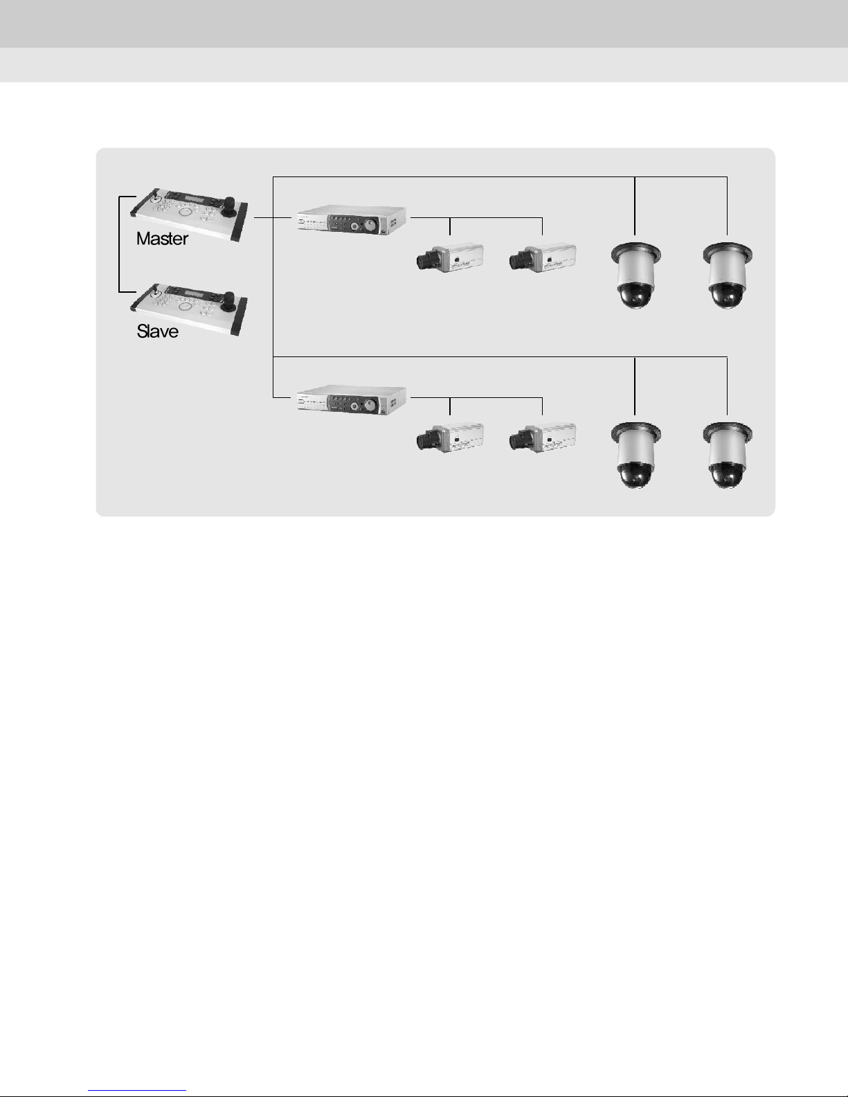
3) Multiple keyboards to multiple devices
Master
Slave
Chapter 3. System Connections
15
Page 16
Chapter 4. How to use
4.1 Log In
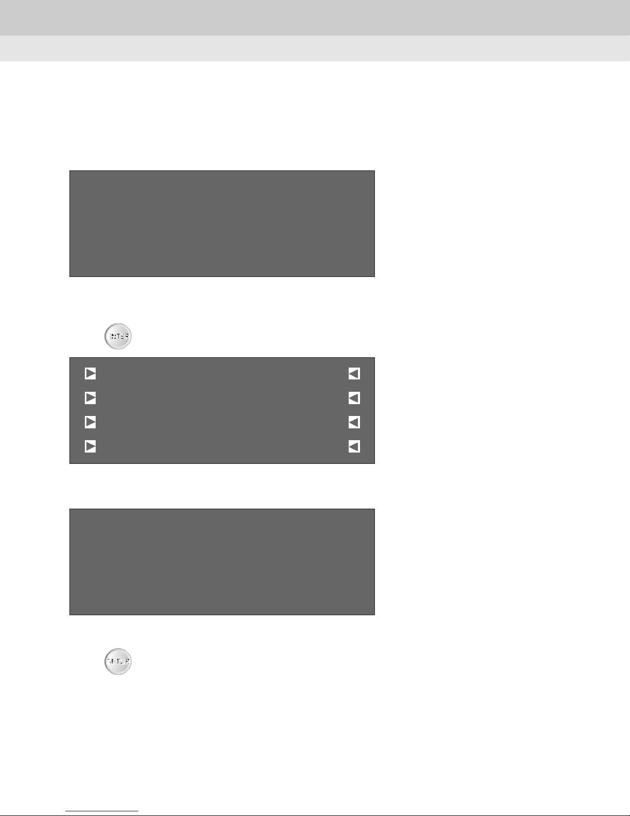
1) How to log in
Log - in Pass word
Inp ut 4 d igit
[ 0 000 ]
Factory default value is "0000"
Chapter 4. How to use
Press button and the followed picture will be shown.
ENTE R
SUNKWANG CAM: 001
Preset
AutoPan
ScanPan
[
[ ][ ]
[[
[[
Pattern
Aux
Stop
]
]]
]]
2) How to set Password
Log - in Pass word
Inp ut 4 d igit
[ 0 000 ]
Enter passwords to log in.(Factory default value is "0000")
Press button to change passwords.
SETUP
16
Page 17
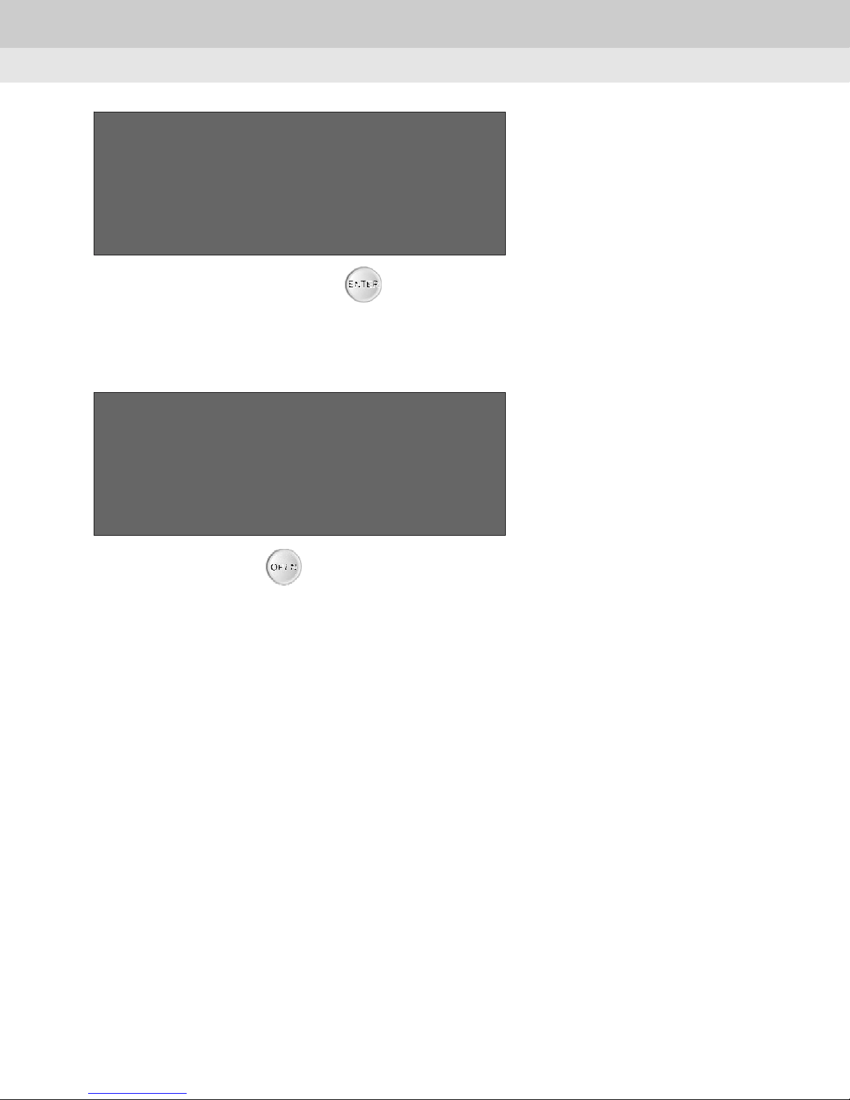
NE W PAS SWORD
Inp ut NEW PAS SWOR D
[ 0 000 ]
Chapter 4. How to use
Enter new passwords and press button.
ENTER
Please remember passwords.
< >
In case of forgetting your passwords.
Log - in Pass word
4 d igitInp ut
[ 1 897 ]
Enter "1897" and press button.
You can see the first 2 digits of your passwords.
OPEN
17
Page 18
4.2 Infomation
Chapter 4. How to use
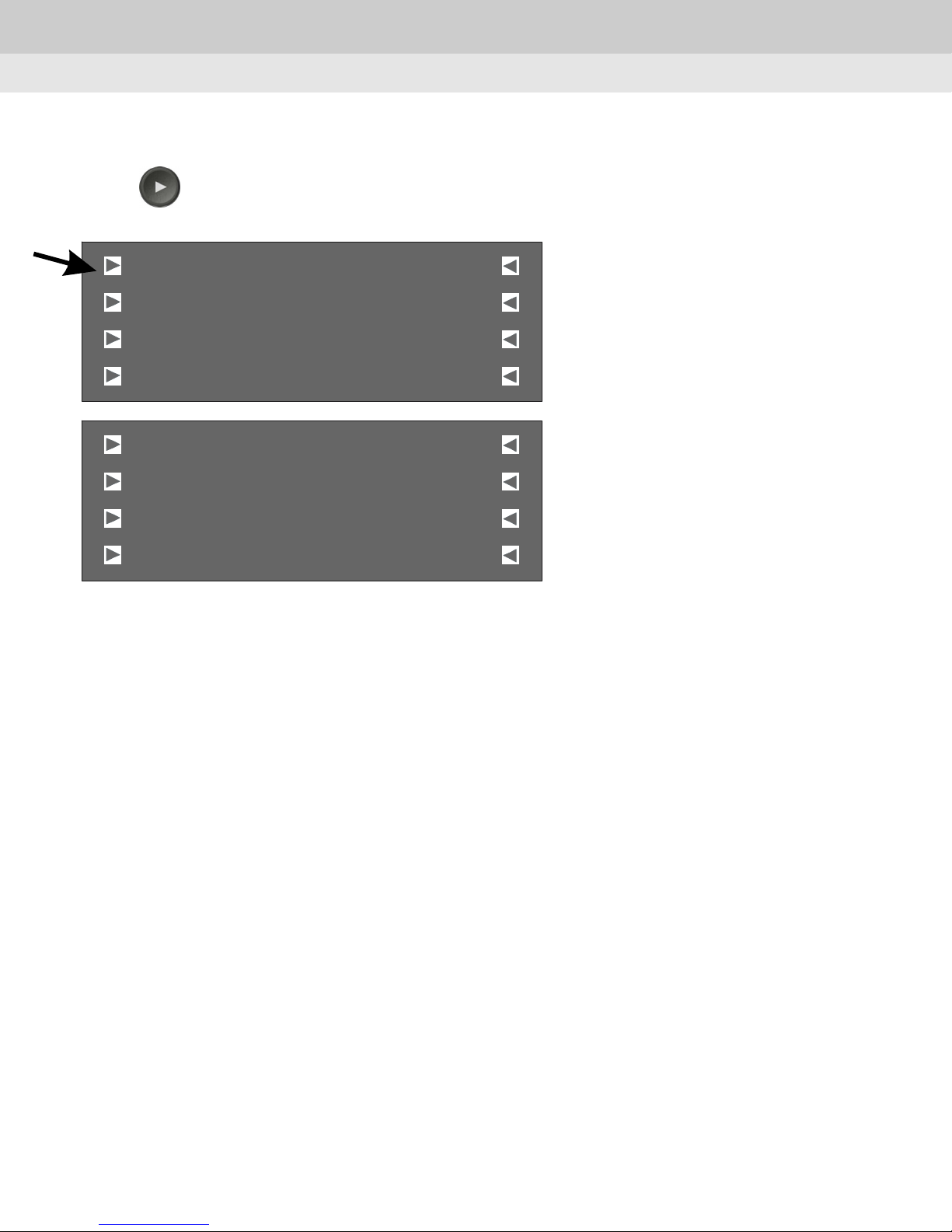
Press button and LCD on controller will be shown as follow.
The information would be different according to the camera.
F1
SUNKWANG
Preset
AutoPan
ScanPan
CAM:001
[
Pattern
[ ][ ]
[[
[[
Aux
Stop
]
]]
]]
Infoma tion
Camera N umbe r :001
Protocol
Baudrate
:Sunkwang
:2400bps
18
Page 19
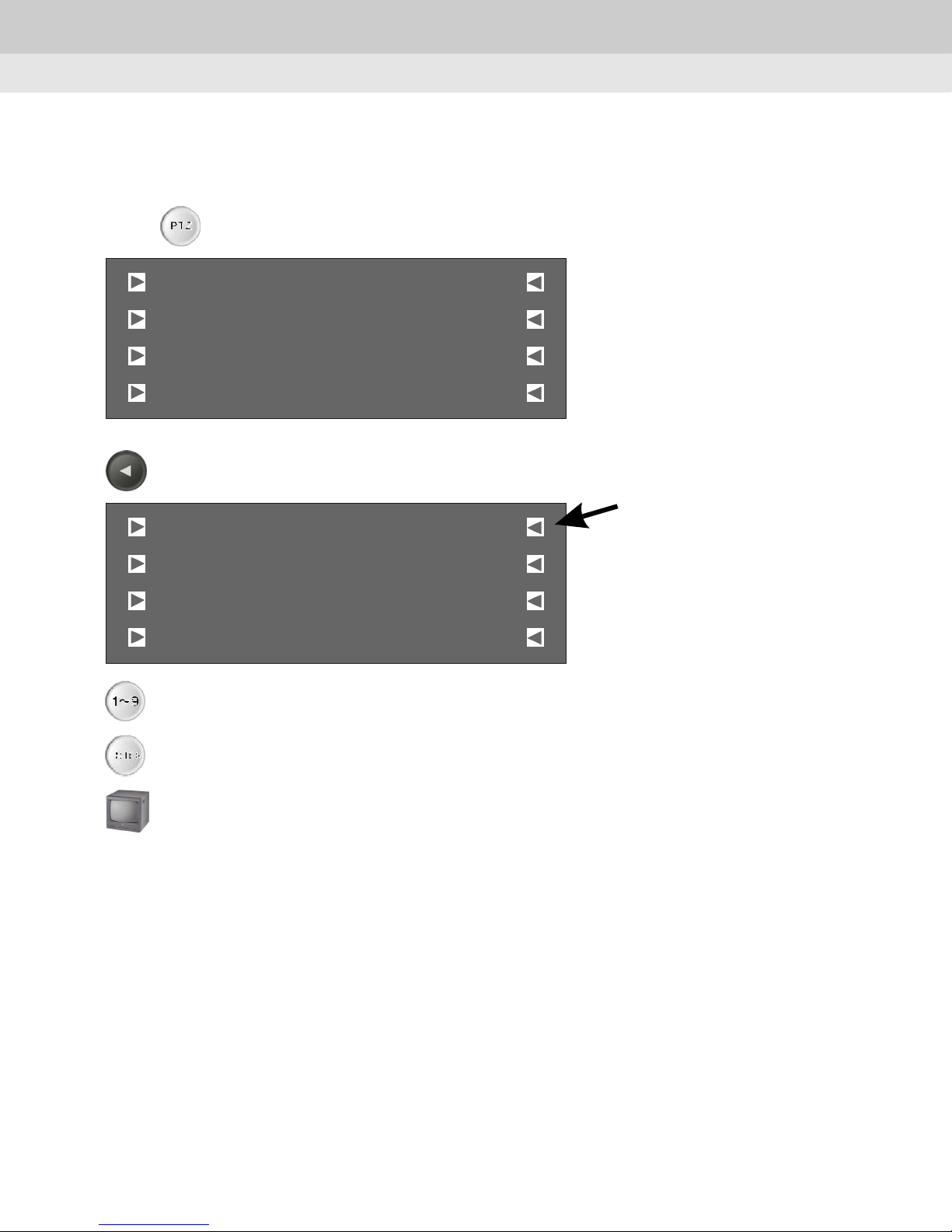
4.3 Control PTZ
1) Select PTZ
Chapter 4. How to use
Push button and screen will be shown as follow.
F5
F5
PTZ
CAM:001
SUNKWANG
Preset
AutoPan
ScanPan
Press 'F5' button to activate cursor.
SUNKWANG
Preset
AutoPan
ScanPan
[
Patt ern
[ ][ ]
[[
[[
[
[ ][ ]
[[
[[
Aux
Stop
CAM: 001
Patt ern
Aux
Stop
]
]]
]]
]
]]
]]
1~ 9
Press numeric key to select the camera.
ENTER
ㆍPAN/TILT
ㆍZOOM
ㆍFocus
ㆍIRIS
Press 'ENTER' button to complete selection of the camera.
Check the video signal.
: Press 'TELE' button to zoom in.
: Press 'NEAR' or 'FAR' button to adjust focus.
: Press 'OPEN' or 'CLOSE' button to adjust IRIS.
: Move joystick to control Pan or Tilt.
Press 'WIDE' button to zoom out.
19
Page 20
Chapter 4. How to use
Basic screen displays according to the protocol.
Screen displays would be different according to the protocol as follow.
SUNKWANG
[ ]
Pre se t
Aut oPan
[
Sca nPan
[
WO NWOO
Pre se t
[ ]
Aut oPan
[
Sca nPan
[
CAM :001
[
[ ]
Pattern
Au x
]
]
]
]
[
Sto p
[
CAM :001
[
Pattern
[ ]
Gro up
[
Tour
[
]
]
]
]
]
]
PELCO D
[ ]
Preset
_________
[
_________
[
PELCO P
Preset
[ ]
_________
[
_________
[
CAM: 001
[
[ ]
Pattern
Aux
]
]
]
]
[
St op
[
CAM: 001
[
Pattern
[ ]
Aux
[
St op
[
]
]
]
]
]
]
20
Page 21
Chapter 4. How to use
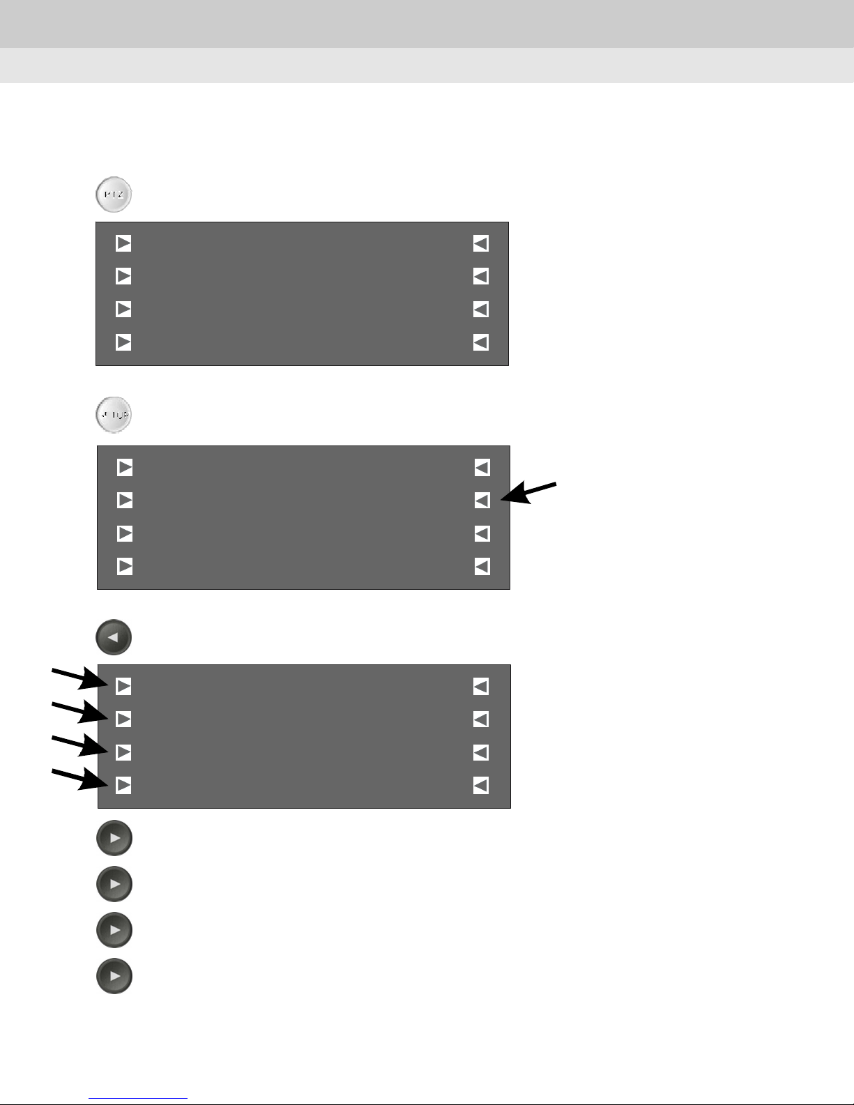
2) Camera Setting
This menu is for setting one or more PTZ units for operation by the controller.
PT Z
Push PTZ button and screen will be shown as follow.
CAM:001
SUNKWANG
[
]
SETUP
F6
Preset
AutoPan
ScanPan
Push SETUP button to go to 'SETUP' menu.
[ ][ ]
[[
[[
Pattern
Aux
Stop
]]
]]
PAN / TILT S E TUP
PTZ DOME
Backlight
Beep
Press F6 button to set PTZ camera.
SET UP
[ ]
LIG HT
[
[
ON
]
]
CAM:001
CAMER A
Protocol
Baudrate
Format
F1
Press F1 : Restore to default value.(SK-P/2400bps)
F2
Press F2 : Restore to default protocol.(SK-P)
F3
Press F3 : Restore to default baud rate.(2400bps)
F4
Press F4 : Format all cameras with current setting.
[
[ ]
[
[[
SK -P
2400bps
Sa ve
21
]
]
]]
Page 22
CAME RA
CAM:001
[
Chapter 4. How to use
]
Protocol
Baudrate
Format
F5
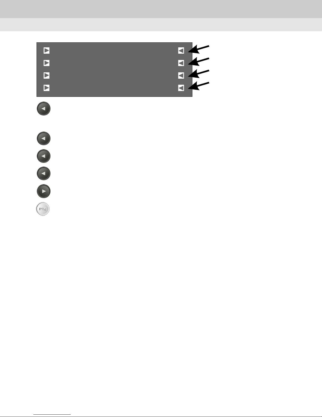
Press F5 button to select PTZ.
[ ]
[
[[
SK -P
2400bps
Sa ve
]
]]
Input a PTZ camera number by numeric key(0~9).
Saved setting value will be shown.
F6
Press F6 button to select protocol.
F7
Press F7 button to select baud rate.
F8
Press F8 button to save setting.
F4
Press F4 button to apply same setting value to all cameras(#1~255).
PTZ
Push PTZ button to go to initial screen display.
22
Page 23
Chapter 4. How to use
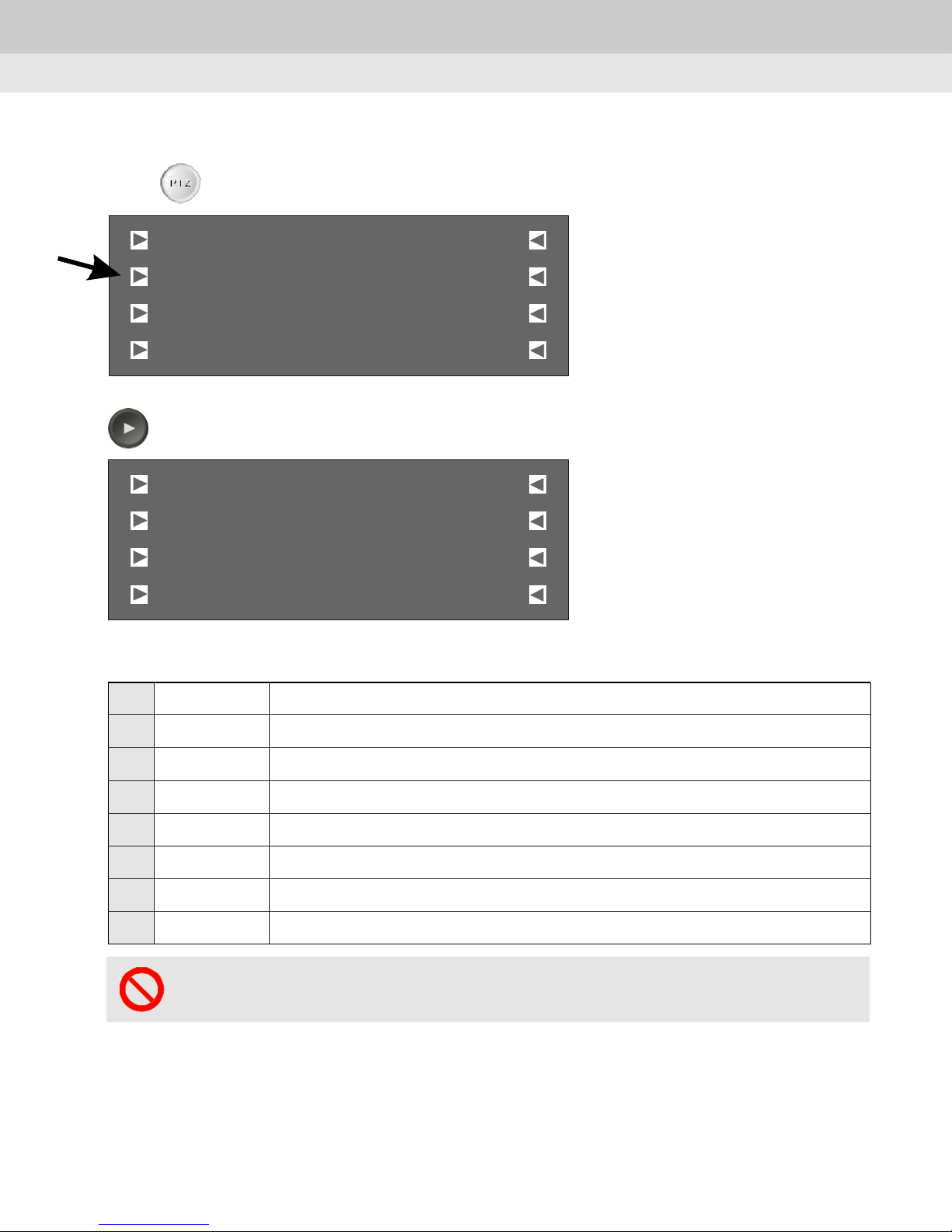
3) Preset - Set the specific position and move to the memorized position
Push button and screen on the controller will be shown as follow.
F2
PT Z
SUNKWANG CAM:001
Preset
AutoPan
ScanPan
Press 'F2' button to select 'Preset'
PRESET CAM:001
SPD:0 00
DWL:000
SAVE
[
Pattern
[ ][ ]
[[
[[
Aux
Stop
[
NUM :000
[ ][ ]
Group:0
[[
MOVE
[[
]
]]
]]
]
]]
]]
Description of menu is as follow.
F1 PRESET Initialize all setting values.
F2 [SPD:000] Movement speed set up
F3 [DWL:000] Dwell time set up
F4 [SAVE] Save the setting values
F5 [CAM:001] Select a camera number
F6 [NUM:000] Set a preset number
F7 [Group:0] Set a group number
F8 [MOVE] Move to the preset location
Notice : Some functions would be not selectable according to protocol.
23
Page 24
Chapter 4. How to use
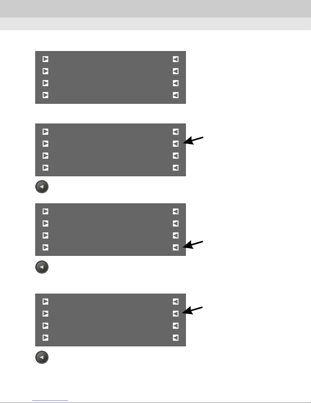
In case of PELCO protocol, screen will be shown as the followed picture.
PRESET CAM:001
___ __ ___
___ __ ___ ____ ____
SAVE
<Preset Movement>
PRESET CAM:001
SPD:0 00
DWL:000
SAVE
F6
Press 'F6' buttion and input the preset number.
[
NUM :000
[ ][ ]
[[
MOVE
[[
[
NUM :000
[ ][ ]
Group:0
[[
MOVE
[[
]
]]
]]
]
]]
]]
PRESET CAM:001
SPD:0 00
DWL:000
SAVE
F8
Press 'F8' buttion to move to the preset location.
<Preset Setup>
PRESET CAM:001
SPD:0 00
DWL:000
SAVE
F6
Press 'F6' button to input a preset number.
[
NUM :000
[ ][ ]
Group:0
[[
MOVE
[[
[
NUM :000
[ ][ ]
Group:0
[[
MOVE
[[
]
]]
]]
]
]]
]]
24
Page 25
Chapter 4. How to use
PRESET CAM:001
SPD:020
DWL:005
SAVE
F2
[
NUM :000
[ ][ ]
Group:1
[[
MOV E
[[
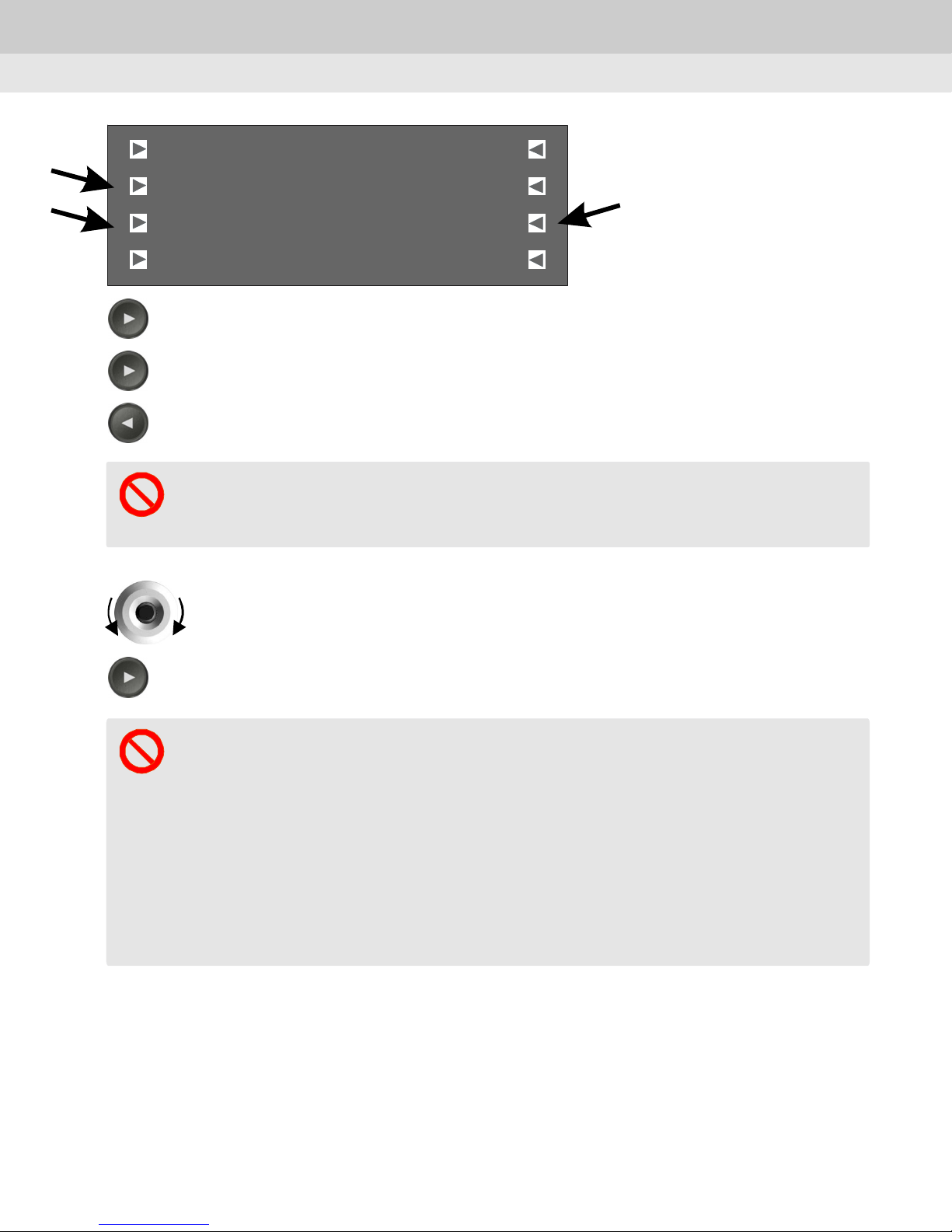
Press 'F2' button to input the preset speed.
F3
Press 'F3' button to set dwell time.
F7
Press 'F7' button to input a group number.
Notice : Some functions would be not selectable according to protocol.
Preset setup is also available in the OSD menu of the connected PTZ
camera.
Use the joystick and zoom control button to move the camera to the desired
]
]]
]]
location.
F4
Press 'F4' button to save the setting values.
Some commands of PELCO-D have special functions other than preset.
1. 33+preset FLIP COMMAND
2. 97+preset RANDOM SCAN
3. 98+preset FRAME SCAN
4. 99+preset AUTO SCAN
- Some would be not available according to protocol.
- Each camera might have some differences between the specification and
real operation.
25
Page 26
Chapter 4. How to use
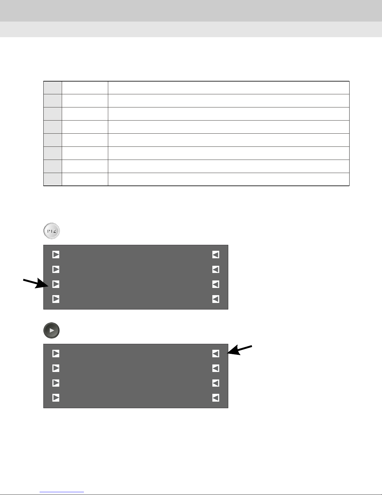
4) Auto Pan Mode
This menu is for setting the camera panning automatically at the fixed speed.
F1 AutoPan Initialize all setting values.
F2 [SPD:005] Set the panning speed.(Default value : 5)
F3 [Custom] Select the type of AutoPan mode.(Default : Custom)
F4 [Start] Operate AutoPan mode
F5 [CAM:000] Set the camera No.(Protocols are not changed)
F6 [1st:000] Set the starting point for preset operation
F7 [2nd:000] Set the ending point for preset operation
F8 [Stop] Stop theAutoPanoperation or move the joystick to stop the operation.
*F6 and F7 buttons for setting of preset operation are only available for the designated
compact PTZ dome camera.
PT Z
Press " PTZ" button and screen on the controller will be shown as follow.
SUNKWANG CAM:001
Preset
AutoPan
ScanPan
F3
Press[AutoPan] button and check the CAM Number you want to operate.
AutoPan CAM:001
SPD:0 05
Custom
Star t
[
Pattern
[ ][ ]
[[
[[
Aux
Stop
[
1st:0 00
[ ][ ]
2nd:000
[[
Stop
[[
]
]]
]]
]
]]
]]
26
Page 27
Chapter 4. How to use
F 2
Press button to control the panning speed.
Max.20 levels are selectable. Higher number means higher speed.
AutoPan CAM:001
SPD:0 05
Custom
Star t
F 3
Press button to set the type of AutoPan mode.
You can choose [Custom], [CW], or [CCW].
*Custom : In case of the speed dome, patrol the area set by the user on "Custom set"
with OSD menu
- CW : Clockwise AutoPan - CCW : Counterclockwise AutoPan.
AutoPan CAM:001
SPD:0 05
Custom
Star t
[
1st:0 00
[ ][ ]
2nd:000
[[
Stop
[[
[
1st:0 00
[ ][ ]
2nd:000
[[
Stop
[[
]
]]
]]
]
]]
]]
Press button to execute the operation.
Press button to stop the operation.
F 4
AutoPan CAM:001
SPD:0 05
Custom
Star t
F 8
AutoPan CAM:001
SPD:0 05
Custom
Star t
[
1st:0 00
[ ][ ]
2nd:000
[[
Stop
[[
[
1st:0 00
[ ][ ]
2nd:000
[[
Stop
[[
]
]]
]]
]
]]
]]
27
Page 28
Chapter 4. How to use
5) Scan Pan Mode
This menu is to move the camera to the memorized positions one by one or randomly.
The minimum of two PRESETs should be saved for this mode.
F1 Scan Pan Initialize all setting values.
F2 [------] No function
F3 [SEQ] Select "SEQ" or "RANDOM".
F4 [Start] Start the operation.
F5
[CAM:000]
F6 [------] No function
F7 [Group:0] Change the group to operate.
F8 [Stop] Stop the operation. Or move the joystick to stop the operation.
Press button to go to "Scanpan" menu.
F 4
SUNKWANG CAM:001
Preset
AutoPan
ScanPan
F5
Check the CAM number.
Set the number of the cameras.(In case of changing the number,
the initial setup menu will be displayed.)
[
[ ][ ]
[[
[[
Group
Aux
Stop
]
]]
]]
In case of changing the number, the initial setup menu will be displayed.
Scan Pan CAM:001
SEQ
Start
[
_____ _________ ____
[ ][ ]
Group:1
[[
[[
Stop
]
]]
]]
28
Page 29
F3
Select "SEQ" or "RANDOM" mode to operate.
Chapter 4. How to use
Scan Pan CAM:001
SEQ
Start
F 7
Press button to select the group.
Scan Pan CAM:001
SEQ
Start
F 4
Press button to execute the operation.
[
_____ _________ ____
[ ][ ]
Group:1
[[
[[
[
_____ _________ ____
[ ][ ]
Group:1
[[
[[
Stop
Stop
]
]]
]]
]
]]
]]
Scan Pan CAM:001
SEQ
Start
F 8
Press "STOP" button or move the joystick to stop the operation.
Scan Pan CAM:001
SEQ
Start
[
_____ _________ ____
[ ][ ]
Group:1
[[
[[
[
_____ _________ ____
[ ][ ]
Group:1
[[
[[
Stop
Stop
]
]]
]]
]
]]
]]
29
Page 30
Chapter 4. How to use
6) Pattern
①This menu is for memorizing the position by panning, tilting, or zoom for a while and
moving the camera to the memorized positions.
See the camera manual for more information.
Pattern Setup
②
PT Z
Push 'PTZ'button and the screen on the controller will be shown as follow.
SUNKWANG CAM:001
Preset
AutoPan
ScanPan
F6
Push 'F6' button to go to 'Pattern' menu.
SUNKWANG CAM:001
Preset
AutoPan
ScanPan
Upon pushing 'F6' button, the screen on the controller will be shown as follow.
[
[ ][ ]
[[
[[
[
[ ][ ]
[[
[[
Pattern
Aux
Stop
Pattern
Aux
Stop
]
]]
]]
]
]]
]]
PATTERN CAM:001
_________
Start
Stop
'F6:NUM' would be selected automatically.
[
NUM:001
[ ][ ]
[[
[[
Ru n
En d
]
]]
]]
30
Page 31
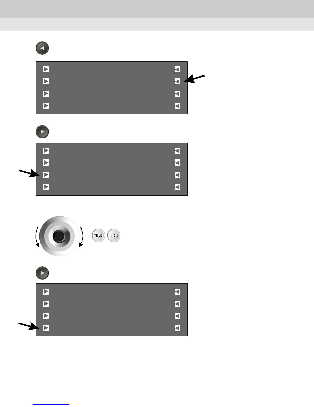
F6F6
When 'F6' is selected, input the pattern number.
1~4 are selectable as a pattern number.
Chapter 4. How to use
PATTERN CAM:001
_________
Start
Stop
F3
Press 'F3' button to set up 'PATTERN'.
PATTERN CAM:001
[
NUM:001
[ ][ ]
[[
[[
Ru n
En d
[
_________
NUM :001
[ ][ ]
Start
Stop
Check the picture for pattern setup on a monitor.
[[
[[
Run
En d
]
]]
]]
]
]]
]]
WIDETELE
Use joystick or Zoom buttons to input camera movements.
F4
Press 'F4' button to save the pattern setup.
PATTERN CAM:001
[
_________
NUM:001
[ ][ ]
Start
Stop
[[
[[
Ru n
En d
]
]]
]]
31
Page 32
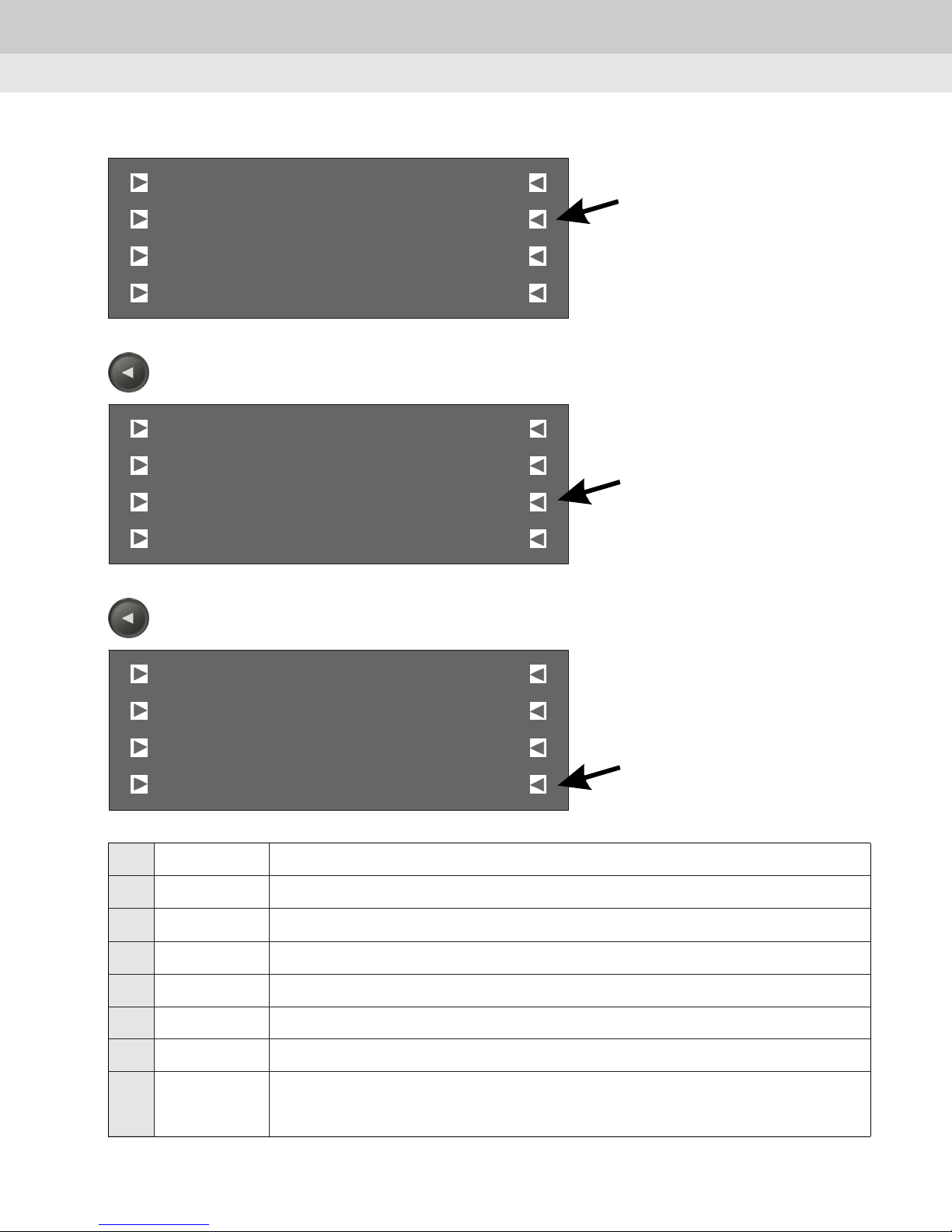
③How to run PATTERN operation.
Chapter 4. How to use
PATTERN CAM:001
[
]
_________
NUM:001
[ ][ ]
Start
Stop
F7
Check the pattern number. Press 'F7' button for pattern operation.
PATTERN CAM:001
[[
[[
[
_________
[ ][ ]
Start
Stop
F8
Press 'F8' button or move the joystick to stop pattern operation.
[[
[[
Ru n
En d
NUM :001
Run
En d
]]
]]
]
]]
]]
PATTERN CAM:001
[
_________
NUM :001
[ ][ ]
Start
Stop
F1 PATTERN No function
F2 [------] No function
F3 [START] Start the pattern setup
F4 [STOP] Stop the pattern setup
F5 [CAM:001] Set a camera number
F6 [NUM:000] Set a pattern number
F7 [RUN] Run the pattern operation
F8
[END]
Stop the patern operation
You can also move the joystick to stop the pattern operation
[[
[[
Run
En d
]
]]
]]
32
Page 33
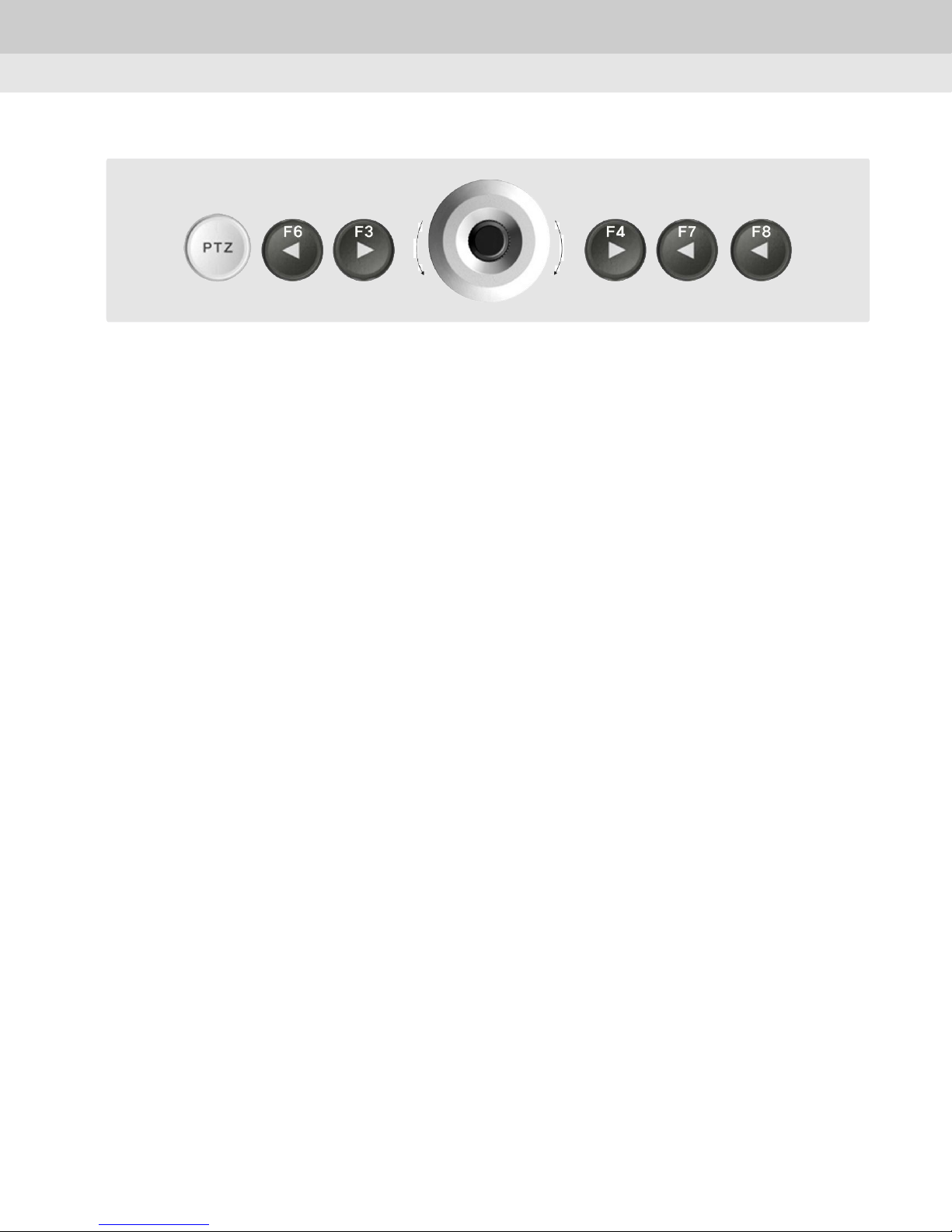
[START] - PATTERN SETUP - [ STOP ] - [RUN] - [END]
Chapter 4. How to use
33
Page 34

Chapter 4. How to use
7) AUX Mode
This function is to control AUX switch in case of any alarm on the cameras, Pelco and
SK-P protocols only support this function.
SUNKWANG CAM:001
Preset
AutoPan
ScanPan
F7
Press 'F7' button to select AUX mode.
AUX CAM:001
NUM: 001
_________
AUX ON AUX OFF
F2
Press 'F2' button to select the AUX number you want to control.
[
Pattern
[ ][ ]
[[
[[
Aux
Stop
[
_________
[ ][ ]
_________
[[
[[
]
]]
]]
]
]]
]]
0~ 9
Input numeric key to select the Aux.
AUX CAM:001
NUM: 001
_________
AUX ON AUX OFF
F4 F8
Press 'F4' or 'F8' to select 'AUX ON' or 'AUX OFF'.
[
_________
[ ][ ]
_________
[[
[[
]
]]
]]
34
Page 35
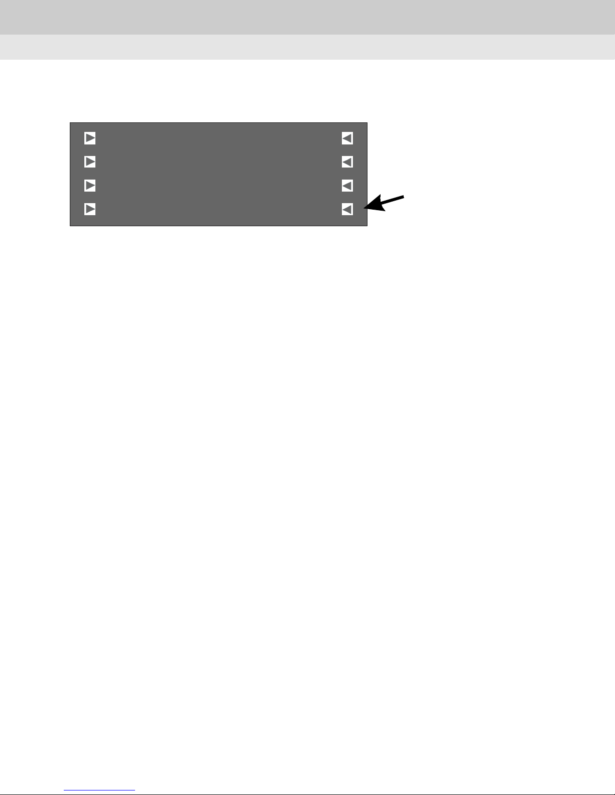
8) Pattern Stop
This function is to stop memorizing pattern operation.
Chapter 4. How to use
SUNKWANG CAM:001
Preset
AutoPan
Scan Pan
[
[ ][ ]
[[
[[
Pattern
Aux
Stop
]
]]
]]
35
Page 36
Chapter 4. How to use
9) Group Mode
①This menu is for setting repeated sequential surveillance of assigned locations with
assigned speed and intervals.
See the camera manual for more information.
②Group Mode
PT Z
Push 'PTZ' button and the screen on the controller will be shown as follow.
WONWOO CAM:001
Preset
AutoPan
ScanPan
F7
Push ' F7' button to go to 'Group' menu.
WONWOO CAM:001
Preset
AutoPan
ScanPan
Upon pushing 'F7' button, the screen on the controller will be shown as follow.
[
[ ][ ]
[[
[[
[
[ ][ ]
[[
[[
Pattern
Gro up
Tour
Pattern
Gro up
Tour
]
]]
]]
]
]]
]]
GRO UP Group1
SPD:000
DWL:000
Shift
[
Group2
[ ][ ]
[[
Group3
Group4
[[
]
]]
]]
36
Page 37
F2
Push 'F2' button to set the movement speed.
Chapter 4. How to use
GROUP Group1
SPD :000
DWL:0 00
Shift
F3
Push 'F3' button to set the dwell time.
GROUP Group1
SPD :000
DWL:0 00
Shift
F5
Push 'F5' button to activate 'GROUP1'.
[
[ ][ ]
[[
[[
[
[ ][ ]
[[
[[
Group2
Group3
Group4
Group2
Group3
Group4
]
]]
]]
]
]]
]]
F6
Push 'F6' button to activate 'GROUP2'.
F7
Push 'F7' button to activate 'GROUP3'.
F8
Push 'F8' button to activate 'GROUP4'.
GRO UP Group1
SPD:000
DWL:000
Shift
[
[ ][ ]
[[
[[
Group2
Group3
Group4
]
]]
]]
37
Page 38
F4
Push 'F4' button to select 'GROUP5' to 'GROUP8'.
Chapter 4. How to use
GRO UP Group1
SPD:000
DWL:000
Shift
Upon pushing 'F4' button, 'GROUP1 ~ GROUP4' and 'GROUP5 ~ GROUP8' are replaced
each other.
GRO UP Group5
SPD:000
DWL:000
Shift
F1 GROUP Not selectable
[
[ ][ ]
Group2
[[
Group3
Group4
[[
[
[ ][ ]
Group6
[[
Group7
[[
Group8
]
]]
]]
]
]]
]]
F2 [SPD:000] Movement speed
F3 [DWL:000] Dwell time(Not available now)
F4 [Shift] Go to next group
F5 [Group 1] Run 'Group 1'
F6 [Group 2] Run 'Group 2'
F7 [Group 3] Run 'Group 3'
F8 [Group 4] Run 'Group 4'
Notice : This mode is only available on WONWOO protocol.
38
Page 39
Chapter 4. How to use
10) Tour Mode
This menu is for setting one or more Groups for Tour so that continuous Group operations
can be carried out.
PT Z
Push 'PTZ' button and the screen on the controller will be shown as follow.
WONWOO CAM:001
Pre set
AutoPan
ScanPan
F8
Press 'F8' button to run 'Tour'.
WONWOO CAM:001
Pre set
AutoPan
ScanPan
Move the joystick to stop 'Tour'.
*This mode is only available on WONWOO protocol.
[
[ ][ ]
[[
[[
[
[ ][ ]
[[
[[
Group
Pa ttern
Tour
Group
Pa ttern
Tour
]
]]
]]
]
]]
]]
39
Page 40
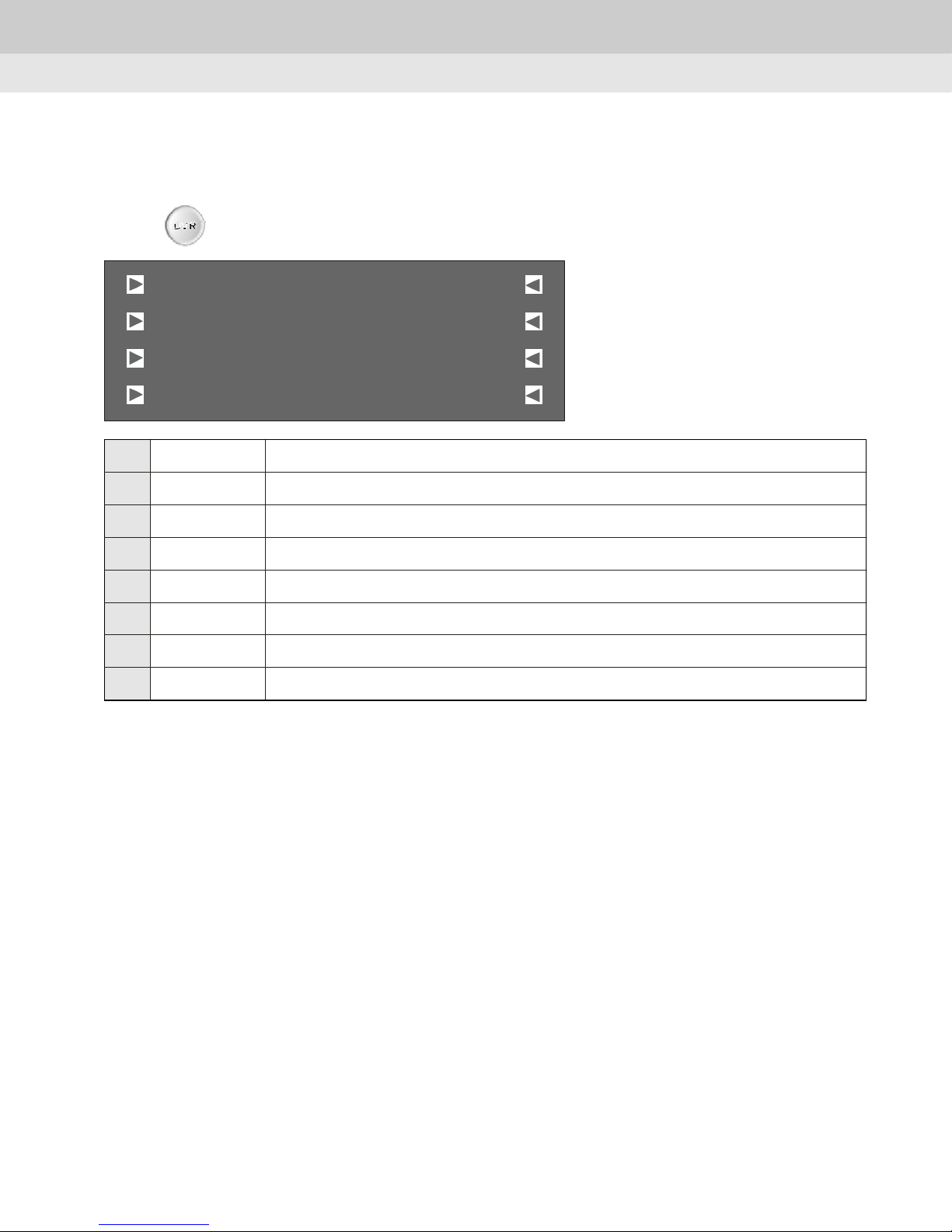
4.4 Control DVR
1) Control DVR Mode
Chapter 4. How to use
Press button and the followed picture will be shown.
F1 [Display] Select display division mode
F2 [Backup] Backup key - To setup backup mode
F3 [Search] Search key - To search recorded data
F4 [Menu] Menu key - Menu display
F5 [FF] FF key - Fast Forward data
F6 [REW] REW key - Rewind data
F7 [Play] Play key - Play data
DVR
Display FF
[ ]
Backup
Search
Menu
[
[ ][ ]
[[
[[
RE W
PL AY
STOP
]
]]
]]
F8 [Stop] Stop key - Stop
40
Page 41
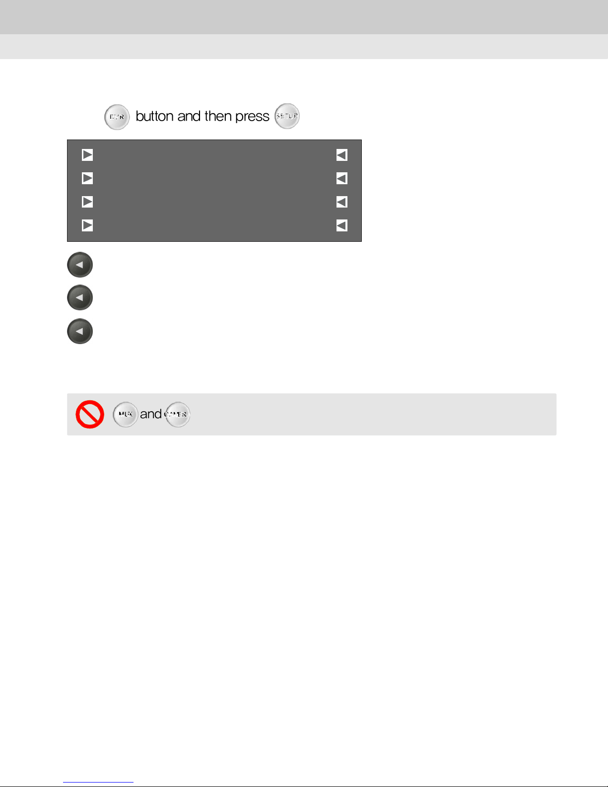
2) DVR Setup
Chapter 4. How to use
Press button and then press button.
DVR
SETU P
DVR SE TUP M ODE
001
TB T
480 0
]
]
F6
DVR ID :
F7
Protocol :
F8
BaudRate :
DVR ID
Proto col
BaudRate
Select address of DVR(Default : 001)
Select type of protocol(TBT protocol only)
Select baudrate of protocol(Default : 4800)
[ ]
[
[
*Support the DVR using TBT protocol only
*For more detail, please refer to the manual of DVR.
CAMERAMUX
and buttons are not available at present.
41
Page 42
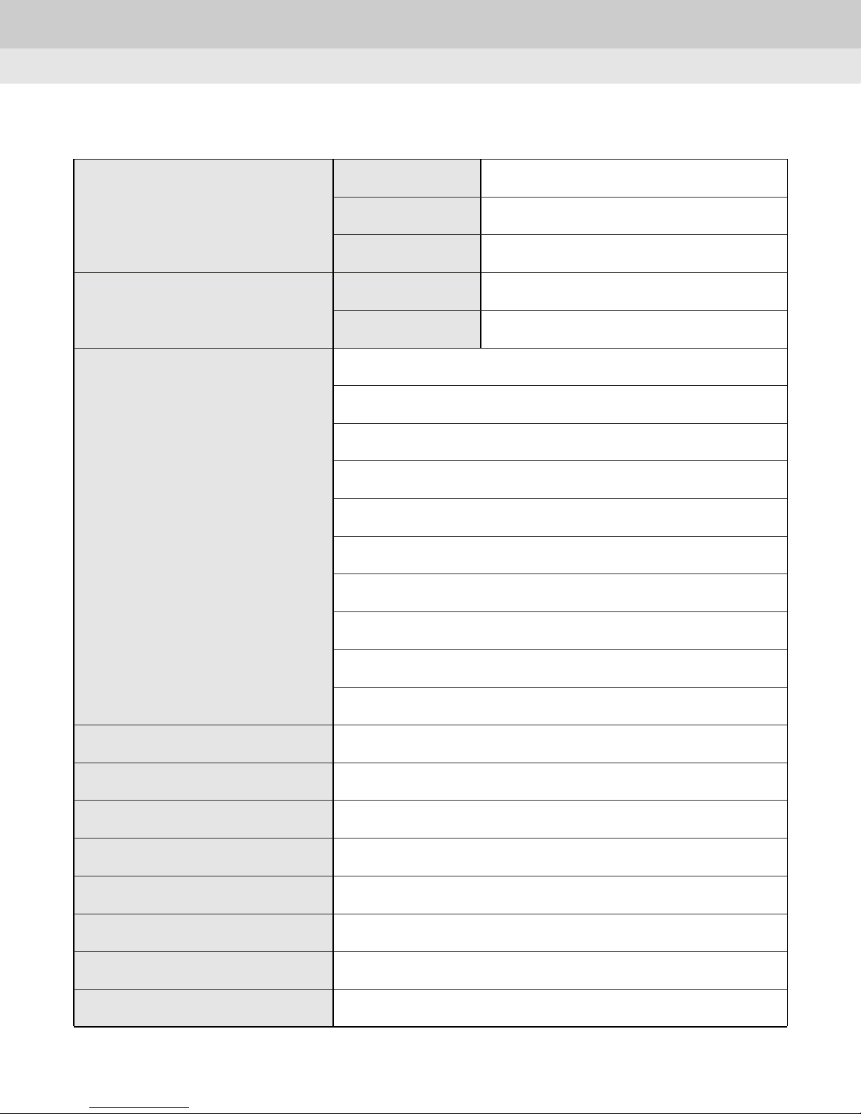
Chapter 5. Specification
Chapter 5. Specification
Control Interface
Joystick
Control
Signal
In/output terminal
Baudrate
Type 1
2
Type
256 Camera ID
Protocol setting
Alarm setting
Pan
Tilt
Zoom operation
RS-485 / RS-422
RJ-45
2400/4800/9600
2 Axis 1ea, 3 Axis 1ea
2 Axis, 2ea
Number of Buttons
Passwords
LCD Display
Current Consumption
Operating Temp. & Humidity
Preservation Temp. & Humidity
Dimension
Iris
Focus adjust
64 preset setting
6 Pattern operation
32
4 digits
Text L D 20 Characters x 4Lines
12V DC, 300mA
-10℃ ~ 50℃ / 0% RH ~ 80% RH
-20℃ ~ 60℃ /
411 X 70 X 190mm
C
0% RH ~ 85% RH
Weight
1Kg
42
Page 43

Chapter 6. Q&A
Chapter 6. Q&A
1. The camera can not be controlled.
- Check the protocols of the cameras.
2. No screen.
- Any shock might cause the malfunction. Please contact the place you purchased.
3. A button is pressed, but nothing is happened.
- Check if you press another button simultaneously.
4. The controller is not compatible with another device.
- Check the setting mode(Master/Slave).
5. Joystick is operating well, zoom and other functions don't work.
- Check the setting value.
6. RANDOM or SEQ mode doesn't work.
- When you set about PRESET menu, you should set GROUP.
7. Forget password.
- Push '1' '8' '9' '7' and 'OPEN' button, and you will see the first two digits.
8. Buttons regarding MENU don't work.
- Check if you push another button simultaneously.
- Check if you set the protocol correctly.
9. With connection oftwo or more controllers,youcannot control the operationof the camera.
- Check if you set Master or Slave correctly.
- Check if the master controller is operating.
* The slave controller is not available when the master controller is operating.
43
Page 44

Please read this manual carefully before installing and using the camera.
Be sure to keep the manual handy for later reference.
3B05690C
 Loading...