

Huvema VBS-2012H-CE Operator's Manual

OPERATOR'S MANUAL
VBS-2012H-CE METALWORKING BANDSAW

- 1 -
First of all, we would like to take this opportunity to thank you for selecting our Vertical Bandsaw.
As you many understand, Vertical Bandsaw is a universal machine for contour cutting. If you
choose a right blade, you are able to make any pattern cutting to any material with this machine.
However, the most important thing is to realize how to operate it in a correct and skillful way, how
to maintain it, and what about the construction of this machine.
We have been trying our best to supply you all the information about these. Please be sure to look
through all the contents in this manual so that you may obtain the maximum efficiency and the
longest machine running, but in the minimum expense.
The specifications contained herein were in effect at the time book was approved for printing. The
supplier, whose policy is one of continuous improvement, reserves the right, however, to change
specifications or design at any time without incurring obligations.
Always include the parts number, model number, and parts description, parts orders or
correspondence concerning your Bandsaw, so we can supply you a rapidly after-sales service.

- 2 -
▲WARNING
1. Read the operator’s manual carefully. Learn the tools applications and limitations, as well as the
specific potential hazards peculiar to it. Know your power tool.
2. Always wear approved safety glasses/face shields while using this machine.
3. Make certain the machine is properly grounded.
4. Before operating the machine, remove tie, rings, watches, other jewelry, and roll up sleeves
above the elbows. Remove all loose clothing and confine long hair. DO NOT wear gloves.
5. Keep the floor around the machine clean and free of scrap material, oil and grease.
6. Keep machine guards in place at all times when the machine is in use. If removed for
maintenance purposes, use extreme caution and replace the guards immediately.
7. DO NOT over reach. Maintain a balanced stance at all times so that you do not fall or lean
against blades or other moving parts.
8. Use only sharp tools. Dull tools are dangerous.
9. Make all machine adjustments or maintenance with the machine unplugged from the power
source.
10. Use the right tool. Don’t force a tools or attachment to do a job which it was not designed for.
11. DO NOT make cuts requiring more power than is available on the machine.
12. Replace warning labels if they become obscured or removed.
13. Make certain the motor switch is in the OFF position before connecting the machine to power.
14. Give your work undivided attention. Looking around, carrying on a conversation. And
“horse-play” is careless acts that can result in serious injury.
15. Make a habit of checking to see that keys and adjusting wrenches are removed before turning on
the machine.
16. Keep visitors a safe distance from the work area.
17. Use recommended accessories; improper accessories may be hazardous.
18. Never place hands directly in line with the saw blade.
19. Always use push sticks when cutting small material.
20. Raise or lower the blade guide only when the machine has been turned off and the blade has
21. Read and understand warnings posted on the machine.
22. DO NOT use attachments for any other purpose than for what they were designed for.
23. Failure to comply with all of these warnings could lead to serious injury.
stopped moving.

- 3 -
POWER SUPPLY
1. Put off the main power switch before
connecting cables.
2. Check motor voltage against supply.
3. Make sure the power supply is
connected to comply with the local
safety regulations.
4. Electric terminal is sited on the right
down of the Electric Box, and up of
▲ WARNING
All electrical connections must be done by a
qualified electrician. Failure to comply may
cause serious injury!
All adjustment or repairs must be done with the
machine disconnected from the power source.
Failure to comply may result in serious injury!
the GROUND. The entrance in is signing L1, L2, and L3 make. The bandsaw must be grounded.
5. Please assure the running direction of blade. It is correct to turn in the same direction as clock. If
opposite, stop the power. Then exchange and connect any two of the three L1, L2, and L3 line.
HANDLING
1. Use a hook for the eyebolt that is equipped on the top of the machine.
2. To handle carefully with forklift chuck.
CLEANING
1. Remove anti-rust oil.
2. Remove the coating with a clean brush applied with paraffin.
3. When the coating has been softened, remove it with clean rag.
INITIAL SETTING
1. Put the table-tilting indicator to “O” position.
2. Use a 90° setsquare, mount it on the table to have the table square with the blade. Adjust it by
putting shins between the table support and the table.
3. Check the table level in vertical way and horizontal way. Adjust it by putting shims under the
base seat.
4. The bandsaw is not necessary to set up the basis job, but please avoid installing at the following
places.
(A). Somewhere another machine is vibrated.
(B). Somewhere is uneven.
(C). Somewhere the materials and finished goods be come in and go out frequently.
(D). Somewhere is not easy to work or repair machine.
- 4 -
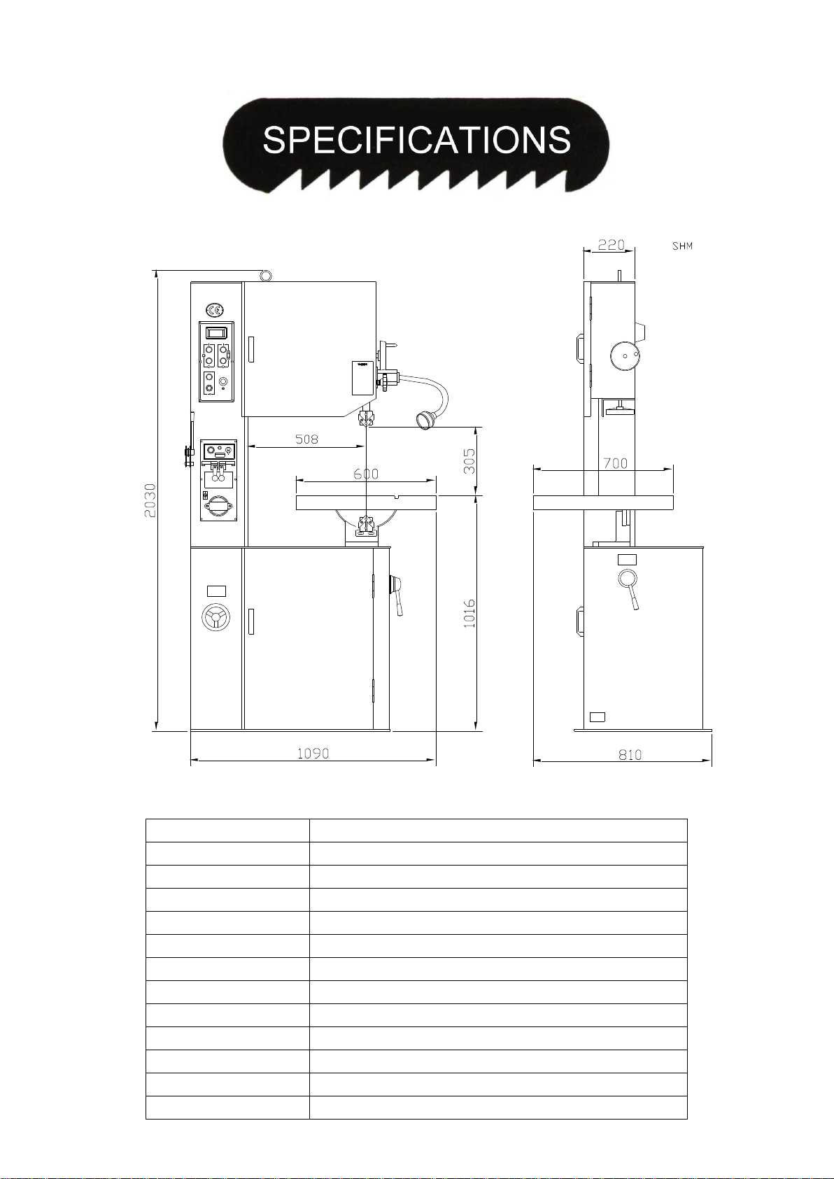
Capacity
508 * 305 mm
Blade Width Cap
3 ~ 25 mm
Blade Speed
15 ~ 1500 M/min
Table Size
600 * 700 mm
Table Tilt
R-45
゚, L
-10゚
Main Drive Motor
400V , 3PHASE, 50HZ, 2.2 KW
Grinder Motor
400V, 3PHASE, 50HZ, 0.04 KW
Blade Length
4035 mm
Blade Welder Cap
4.2 KVA, 6 ~ 19 mm
Band Wheel Diameter
515 mm
Table Height
1016 mm
Dimension
1090 (Length) * 810 (Width) * 2030 (Height) mm
Mach. Weight
590 kgs
- 5 -
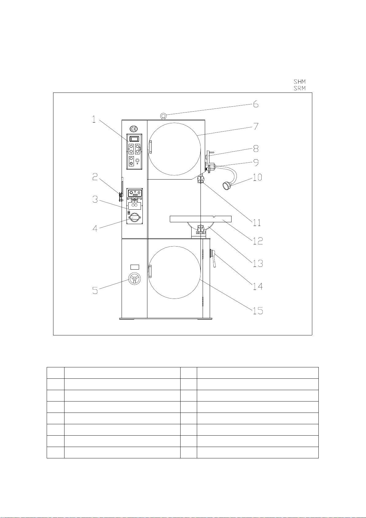
1
Control Board
9
Upper Blade Guide Lock Knob
2
Shear
10
Work Lamp
3
Weld Board
11
Blade Guide Supports
4
Grinding Wheel Motor
12
Work Table
5
Variable Speed Hand Wheel
13
Table Support Housing
6
Hang Ring
14
Low/High Range Shift Lever
7
Upper Wheel
15
Lower Wheel
8
Post Elevating Hand Wheel

- 6 -
Low/High Range Shift Lever –
Located on right side of machine base. Pull
toward the front of the machine to shift into the
low speed range. Push toward the rear of the
machine to shift into the high-speed range.
Caution: Do not change the speed range. While
the machine is running. Adjust only when the
machine is stopped.
Variable Speed Hand Wheel –
Located below worktable on left side of machine
base. Turn clockwise to increase speed and
counter-clockwise to decrease speed.
Caution: Do not turn handle while machine is
stopped. Adjust speed only when machine is
running.
Upper Blade Guide Lock Knob –
Located on right side of upper arm. Turn
counter-clockwise to loosen and clockwise to
tighten.
Upper Blade Guide Hand Wheel–
Located on the upper right side of the saw. Turn
clockwise to raise the blade guide assembly.
Turn counter-clockwise to lower.
Work Lamp Switch –
Turn lamp on and off.
Shear Lever –
Located on upper column. Up position allows
increase insertion of blade end into shear. Pull
lever DOWN to cut blade.
Weld Button –
Located on blade welder panel found on column
front. Depress and hold to start welding. Shuts
off automatically when weld is done. Release
when weld is completed.
Anneal Button –
Located on blade welder panel found on column
front. Depress and hold to anneal blade, release
to stop.
Blade Clamp Pressure Knob –
Located on blade welder panel found on column
front. Sets pressure for different width blades.
Blade Clamps –
Located on blade welder panel found on column
front. DOWN position allows insertion of blade
into clamp. Up position locks blade.
Blade Tension Hand Wheel –
Located on underside of upper frame. Turn
clockwise to tension blade; counter-clockwise to
release tension on blade.
Blade Tracking Hand Wheel –
Located at the upper rear of the saw. Turn
clockwise to track blade toward front of the blade
wheel Turn counter-clockwise to track blade
toward rear of the blade wheel.
Table Tilt Mechanism –
Located under worktable. To tilt table left or
right, loosen hex cap screws at rear of
mechanism.
Digital Readout –
Located on the control panel. Indicates blade
speed in feet per minute. Note: After the saw is
first started or the speed has been changed, allow
a least a minute for the readout to stabilize to the
new setting.
Key Lock Switch –
Turn to 12 o’clock position and remove key to
lock out power from the control panel.
Power indicator Light –
Indicates that power to the control panel is on.
Main Motor Start Switch –
Depress to start bandsaw.
Main Motor Stop Switch –
Depress to stop bandsaw.
Grinder Motor Start Switch –
Depress to start grinder motor.
Grinder Motor Stop Switch –
Depress to stop grinder motor.
Emergency Stop Switch –
Press to stop machine. Turn 90° to reset.
▲CONTROL
- 7 -
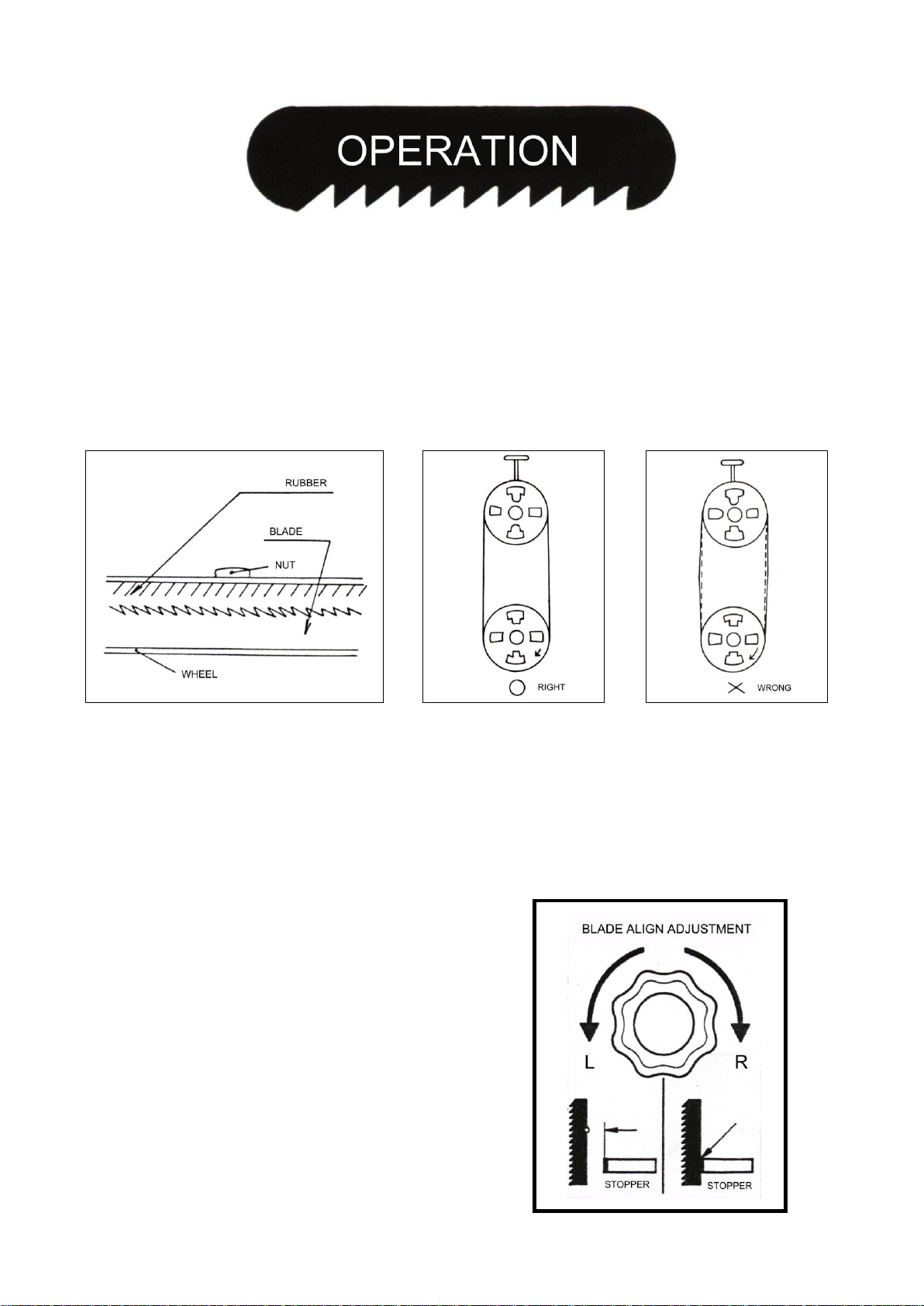
1. Turn blade tracking knob clockwise to track blade
toward front of blade wheel.
2. Turn counter-clockwise to track blade toward rear
of blade wheel. Blade should be tracked as close of
the center of the top blade wheel as possible.
▲Note: Upper and lower blade guides should be
moved away and left loose from the blade
while tracking adjustments are being
made.
BLADE SETTING
1. Assemble blade as illustrated.
2. Adjust blade tension according to the Tension Scale by turning the Blade Tension Adjust Hand
Wheel.
3. Run machine to see if the blade tracks well or not, adjust blade tracking by turning Wheel Tilting
Adjuster when it is necessary.
BLADE TRACKING
Blade tracking may be required from time to time depending on the blade size and tension.
Disconnect the machine from the power source and open both blade wheel doors. Shift the high-low
gearbox lever into the neutral position. Turn the upper blade wheel by hand while observing blade
position on the upper blade wheel if adjustment is necessary:
- 8 -
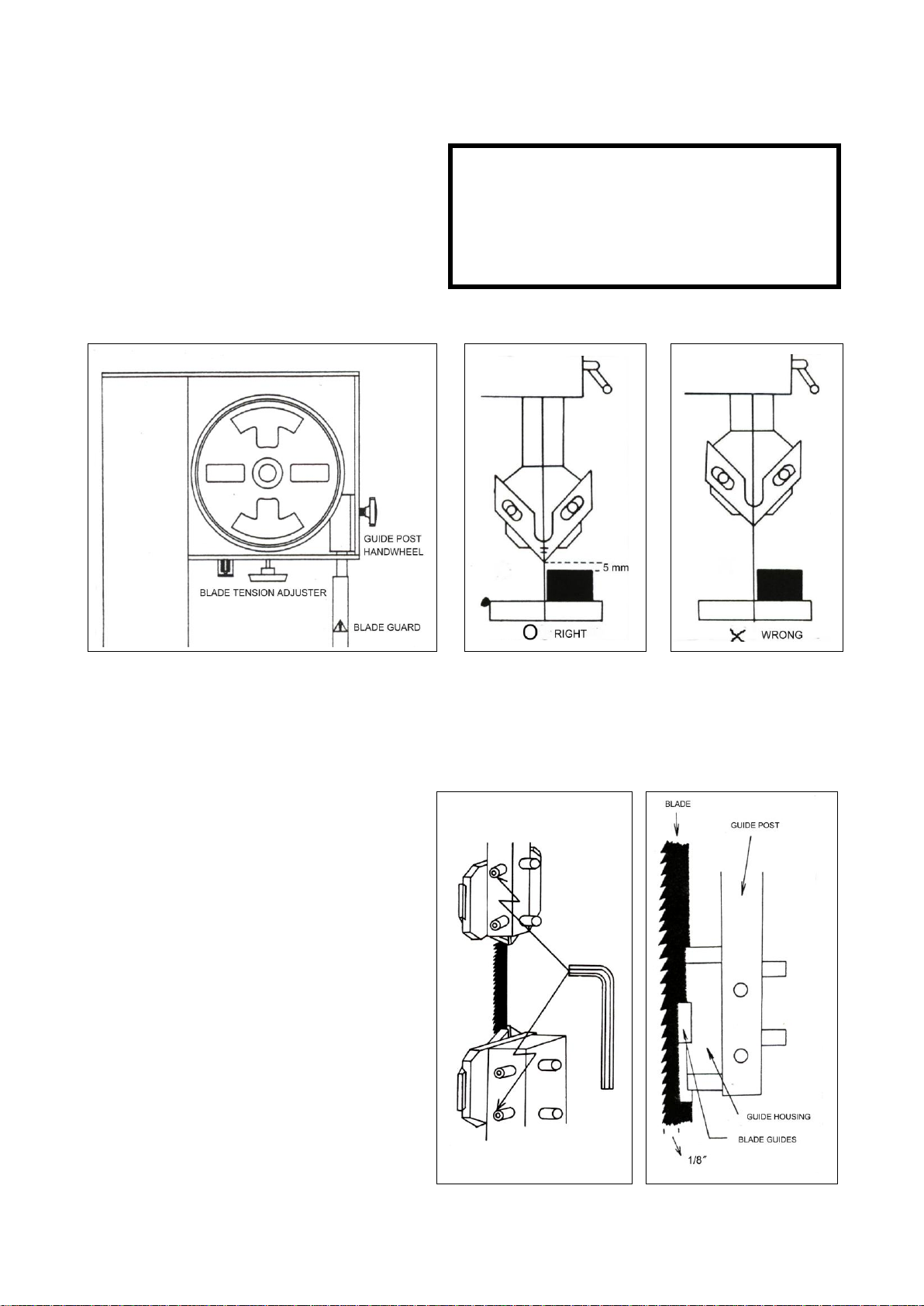
GUIDE POST ADJUSTING
1. Loose the Guide Post Locker.
2. The height of the lower or upper Guide
Post is according to the object. The
height between the object and the blade
guide end is suggested to be about 1/4”.
3. Lock the Guide Post tightly.
▲ WARNING
All adjustment or repairs to the machine must
be done with the power off and the machine
disconnected from the power source. Failure
to comply may result in serious injury!
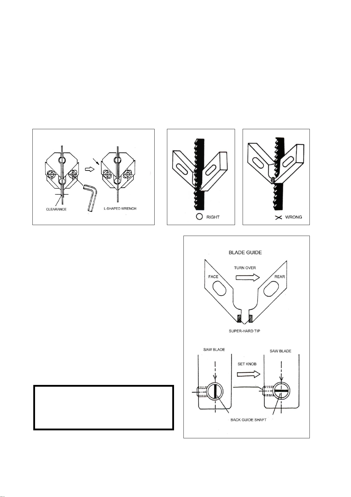
GUIDE HOUSING ADJUSTMENT
1. Loose the inner hexagonal screws
located at the rear side with an “L”
shaped spanner.
2. Adjust the Guide Housing forward or
backward according to the blade width.
The front end of the Blade Guides must
be adjusted about 1/8” behind the blade
teeth.
3. Lock the screws tightly.
▲ Please notice if it is necessary to open the Blade Guide first, before you adjust the Guide Post
to upper.
- 9 -
BLADE GUIDE ADJUSTING
The Blade Guide will be worn at the front end as
it is used. If the Blade Guide is hard to be
adjusted, turn the left Blade Guide over to the
right side, as illustrated in the right figure, and
turn the right side Blade Guide over to the left
side as well. The Blade Guide can thus be used on
both sides.
The Blade Guide Shaft will be worn as it is used
and its friction with the saw blade may cause a
worn line in its surface. It this is found, loosen the
set knob and turn it to either side to change the
knob position on the saw blade.
▲ CAUTION
Blade guide must be properly adjusted or
damage may occur to the blade and/or the
guides.
1. Loose the inner hexagonal screws of the Blade Guide with an “L” shaped spanner.
2. Adjust the Blade Guide to be very close to the blade but do not be touched.
3. Lock the Blade Guides tightly.
NOTE: There are totally four Blade Guides and two Guide Housings located above the table and
under the table, all to be adjusted to the same position.
 Loading...