

HU 25 T
DRILLINGM MACHINES

2
CHANGES AND TYPING ERRORS RESERVED CHANGES AND TYPING ERRORS RESERVED
Table of conTenTs
1. General safety rules for all machines 3
2. Main specifications and features 4
3. Several usage regulations 4
4. Main specifications & parameters 4
5. Parts drawings and list 5
6. Structure and adjustment 9
7. Transmission system 9
8. Operation 9
9. Lubrication 10
10. Transportation and installation 10
11. Electric system 10
12. Accessories 11

3
Drilling machine hU 25 T
1.
general safeTy rUles for all machines
N.B.: Read the instructions carefully in order to avoid any problems.
As with all machinery there are certain hazards involved with operation and use of this machine. Using the
machine with respect and caution will considerably lessen the possibility op personal injury. However, if normal
safety precautions are overlooked or ignored, personal injury to the operator may occur. Observe these rules
insofar as they are applicable to this particular machine.
This machine was designed for certain applications only. We strongly recommend that this machine NOT be
modified in any way and/or used for any application other than for which it was designed.
If you have any questions relative to its application DO NOT use the machine until you have contacted your
dealer.
1. For your own safety read the instruction manual before operating the tool.
2. Keep all guards in place and in working order.
3. Ground all tools.
4. Remove adjusting keys and wrenches. Make a habit of checking the machine before turning it on.
5. Keep the work area clean. Cluttered areas and benches invite accidents.
6. Do not use in a dangerous environment, such as damp or wet locations or expose to rain. Always keep the
work area well-lit.
7. Keep children and visitors away. They must be kept at a safe distance from the machine at all times.
8. Make sure that the work area is not accessible to unauthorised persons. Use padlocks, master switches,
remove starter keys etc.
9. Never overload the machine. The capacity of the machine is at its largest when properly loaded.
10. Do not force the machine or attachment to do a job for which it was not designed.
11. Wear proper apparel. No loose clothing, gloves, neckties, rings, necklaces, bracelets or jewellery: they may
get caught in moving parts. No slip footwear is recommended. Wear a hairnet to contain long hair.
12. Always wear safety glasses and work according to safety regulations. Use a face or dust mask if operation is
dusty.
13. Always secure workpiece tightly using a vise or clamping device. This will keep both hands free to operate
the machine.
14. Do not overreach. Keep your proper footing and balance at all times.
15. Maintain tools in top condition. Keep them sharp and clean. Read the instructions carefully and follow the
instructions for cleaning, lubrication and tool replacement.
16. Lubricate the machine and fill all oil reservoirs before operation.
17. Disconnect tools before servicing and when changing accessories such as blades, bits, cutters etc.
18. Use only recommended accessories. Consult the owner’s manual for recommended accessories. The use of
improper accessories may cause hazards.
19. Avoid accidental starting. Make sure the on/off switch is in the “OFF” position before plugging in the power
cord.
20. Never stand on the machine or tools. Serious injury could occur if the machine is tipped or if the cutting tool
is accidentally touched.
21. Check damaged parts. Replace or repair damaged parts immediately. Check machine for alignment of
moving parts, binding of moving parts, breakage of parts, mounting and any other conditions that may
affect its operation.
22. Direction of feed. Feed work into a blade or cutter against the direction of rotation of the blade or cutter only.
23. Never leave tool running unattended. Do not turn power off until it has come to a complete stop.
24. Alcohol, medication, drugs. Never us the machine while under the influence of alcohol, medication or drugs.
25. Make sure the tool is disconnected from the power supply, before servicing, repairing etc.
26. Keep the original packing for future transport or relocation of the machine.

4
CHANGES AND TYPING ERRORS RESERVED CHANGES AND TYPING ERRORS RESERVED
Additional safety rules
Always keep in mind that:
• the machine must be switched off and disconnected from the power supply during maintenance and repairs,
• clamped workpieces may only be measured when the machine is switched off.
Never lean over the machine, mind loose clothing, ties, jewellery etc. and wear a cap.
Do not remove safety devices or guards. Never use the machine while a guard is open.
Always use safety glasses for machining rough materials.
Burrs and chips should only be removed using a sweeper or other aid, never with your bare hands!
Never leave the machine running unattended.
Always wear safety glasses.
2. M
ain specificaTions anD feaTUres
This is a general- purpose drilling machine for hole machining operation. Two sets of motions, one is the
rotational movements of the spindle in its transmission box, the other is the rotational and vertical travel
movements of the spindle box along the vertical column, fulfil the machining operations of drilling, tapping,
reaming, boring, chamfering and spotfacing on different shapes of workpieces. The gear transmission system has
been applied, Which results in the compact structure and high rigidity to meet the needs of strong force cutting
operation. The double-speed motor has led a wide speed range and very easy and safe shifting. The drilling
machine suits the needs of machinery manufacturing and various kinds of repairing applications.
3.
several Usage regUlaTions
1. Carefully read this user manual before start the machine.
2. Wearing gloves is not allowed when operate this machine, contacting the spindle and tools are also
forbidden when it is running.
3. The workpiece must be safely fastened, holding it with hands when in operation is strictly objected.
4. The machine has not short – circuit protection, the user is so required to connect a 6A protection switch.
Earth protection mist be well done.
5. Whenever a failure happens, call the qualified personal to repair it.
4.
main specificaTions & parameTers
Max. drilling dia. 25mm
Max. Spindle travel 150mm
Spindle hole taper Morse No.3
Spindle speed variations 8
Speed Speeds 50Hz: 100 250 345 440 690 885 1450 2900rpm
60Hz: 126 245 415 530 830 1060 1740 3480rpm
Distance between spindle centre line and
vertical column surface
225mm
Bottom base dimension 300 X 305
Max. Distance between spindle face and
bottom base
445mm
Double-speed, 3 phase 0.55/0.75KW,
50Hz: 1400/2800rpm
60Hz: 1680/3360rpm
Machine overall dimension 58X470X1000mm
Weight 170kg
5
5.
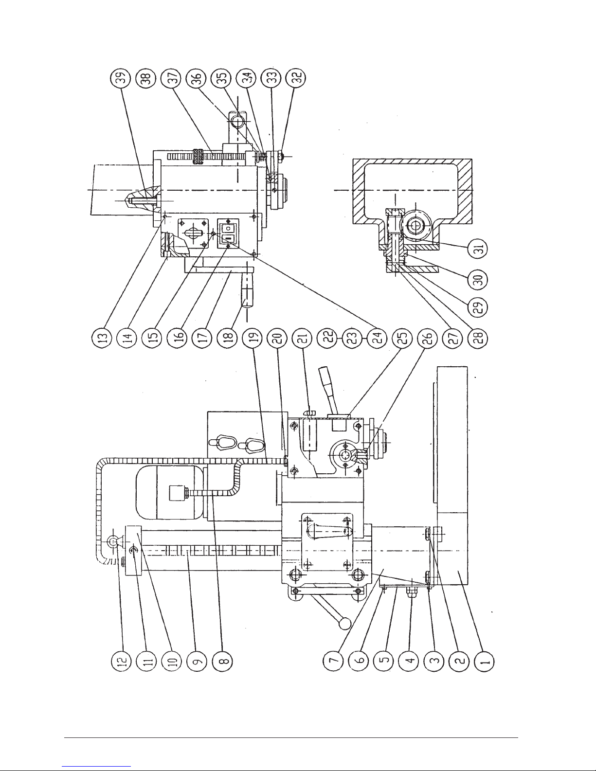
parTs Drawings anD lisT
Figure 1
Figure 2
Figure 3

6
CHANGES AND TYPING ERRORS RESERVED CHANGES AND TYPING ERRORS RESERVED
Figure 4
Figure 5

7
Figure 6
Figure 7

8
CHANGES AND TYPING ERRORS RESERVED CHANGES AND TYPING ERRORS RESERVED
No. Description No. Description
1 Bottom base 69 Spindle box
2 Spring washer 70 Fasten bolt
3 Hex nut 71 Round head fasten screw
4 Hose connector 72 Hex nut
5 Cover plate 73 Cover nut
6 Round head screw 74 Round head nut
7 Vertical column 75 Cover plate
8 Flexible metal pipe 76 Sink screw
9 Lift gear rack 77 Sink screw
10 Vertical column top cover 78 Coil spring
11 Inner hex screw 79 Cover plate
12 Eye screw 80 Spring base
13 Cross slot screw 81 Lift gear shaft z16
14 Inner hex screw 82 Electric panel
15 Carth plate 83 Round head fasten screw
16 Cross slot screw 84 Spring
17 Handle 85 Round head screw
18 Handle 86 Ruler base
19 Flexible metal prpe 87 Spring sleeve
20 Hose connector 88 Handle rod
21 Change switch 89 Handle sleeve
22 Sping washer 90 Gear box
23 Toothed washer 91 Gear box
24 Round head screw 92 Round head screw
25 Electromagnetic 93 Taper pin
26 Tapered head fasten screw 94 Bearing 80203
27 Round head screw 95 Gear z42
28 Worm shaft 96 Key
29 Taper pin 97 Sleeve
30 Bush 98 Key
31 Bearing 8102 99 Gear z16
32 Hex nut 100 Gear z68
33 Taper head fasten screw 101 Cover
34 Round pin 102 Gear z16
35 Spring 103 Motor connect shaft
36 Washer 104 Motor base
37 Scaled ruler 105 Round head screw
38 Knurled nut 106 Key
39 Round head screw 107 Sleeve
40 Round nut 108 Gear z34
41 Anti-motion washer 109 Sleeve
42 Bearing 80205
e
110 Round head screw
43 Guide key 111 Middle shaft
44 Spindle sleeve 112 Cover plate
45 Feed gear rack 113 Motor
46 Spindle 114 Key
47 Round head screw 115 Rivet

9
48 Handle 116 Center shaft
49 Sleeve fasten ring 117 Sleeve
50 Bearing 7206
e
118 Connect sheet
51 Bearing cover 119 Gear z33
52 O shape seal 120 Inner gear sheet
53 Oil cup 121 Connector
54 Taper head fasten screw 122 Key
55 Fixture sleeve 123 Gear z51
56 Key 124 Sleeve
57 Worm gear z28 125 Bearing 3056203
58 Sleeve 126 Gear z42
59 Small shaft 127 Fixture ring
60 Gear z17 128 Taper ring
61 Connection rod 129 Pin
62 Handle base 130 Arm
63 Handle ball 131 Shaft pin
64 Handle bar 132 Tape pin
65 Handle base 133 Handle
66 Pin 134 Spring
67 Elastic block ring 135 Steel ball
68 Washer
6.
sTrUcTUre anD aDjUsTmenT
The vertical column is mounted on the bottom base, loosen the fasten handle 63 ( fig.5 ) and rotate handle 17
( fig.2 ), the spindle box can move along the vertical column, loosen the fasten handle 63, the spindle box fixed
at any position, so to suit the different machining requirements, loosen cover nut 73 ( Fig.5 ) and rotate nut 72,
the swivel angle of the fasten handle can be adjusted and the tightness of the spindle box can also be changed,
when adjustment completes, fasten the cover nut.
The gear box is mounted on top of the spindle box, rotate the feed handle 89 ( Fig.5 ) the spindle will move up
and down along with the sleeve Remove the gear box, loosen the anti-motion washer 41 ( Fig.4 ), adjust nut 40,
the clea ance of the spindle bearing can be altered. The above adjustments have been set when put to shipment,
nonqualified personal is not allowed to de this adjustments.
7.
Transmission sysTem
The spindle rotate ( Fig. 6 ) through motor and gear 95;126 or 99;100 to shaft . Through gear 102; 123 or 108;119
to shaft. Through guide and transmission key to spindle. The motor has double- speed, through changing the
transmission gears, the spindle will rotate in 8 grades of speeds.
Spindle feed motion. The spindle feed movement is controlled manually, the handle 88 ( Fig.5 ) through gear,
gear rack transmission, to make the spindle sleeve move downwards so realise the feed motion.
The up and down motion of the spindle box. It is also controlled by hand, loosen the fasten handle 63 ( Fig. 5 ),
move handle 17 ( Fig.2 ), the spindle box will move up or down.
8.
operaTion
Before start the motor, first rotate the change switch ( 21 ) on the spindle box till teach the required position (
high speed to “2R”, Low speed to “1R”, low speed and reverse direction to “1L” ) , then press down the start switch
“1” (green) ; for stop the machine press “O” button ( red ): for reverse rotation, fist to stop the machine and rotate
the speed change switch to “1L” or “2L” wait till the motor to stop completely and then press the start switch.
The speed selection is realised through handle 133 ( Fig.7 ), adjust handle 133 to realise 4 kinds of speed
variations, matched with double speed motor, we can gain 8 grades of speeds ranging from 100 rpm to 2900 rpm.
It should be noted that the speed variations could only be done when the machine has stopped so to avid any
possible damages to the gears and couplers.
About the drilling depth, you only need to adjust the nut 38 ( Fig.2 ) to the require dimension. The drill automatic
release applies to GB1443-85 (ISO 296-1974 ). Morse 3 outer taper with flat tail, its operation is 1:ke this: put out
the handle 48 ( Fig.4 ), rotate handle 88 ( Fig.5 ), then the sleeve will lead the drill to the highest position, the drill
end touches the enter shaft end so to be pushed out, then push 48 to its original position, install the tool.

10
CHANGES AND TYPING ERRORS RESERVED CHANGES AND TYPING ERRORS RESERVED
9.
lUbricaTion
The spindle sleeve lubrication uses precision machine tool grease No. 2, change it every 1 year, The spindle box
handle should be oiled every shift using No. 30 oil.
10.
TransporTaTion anD insTallaTion
Before lifting the machine for transportation, the spindle box must be fastened first.
The machine can be installed on any hard place, it can also be tightened by bolts.
11.
elecTric sysTem
SA connection (“X” means connected)
No. LW6-4/F525 No. Low speed 0 High speed
1L
CCW
0 1R
CW
2R CW0 2L
CCW
1 2 X X
3 4 X X
5 6 X X
7
8
X X
9
10 X
X
11
12
X X
13
14
X X
15
16
X X
17
18
X X
19
20 X
X
21
22
X X
23 24 X
X
connect a 6A protection switch
Figure 8

11
The circuit diagram is shown as Fig. 8, the electric connection is shown as Fig. 9. The machine uses 3 phase, 50Hz
or 60Hz, 220V, 380V, 420V power supply, which are user selectable.
The double-speed motor rotates at 1400/2800 rpm for 50Hz and 1680/3360 rpm for 60Hz, the motor power is
550/750W, the two speeds are selected by SA switch, the reverse direction can also be selected, the start and stop
are realised by push button QS.
12.
accessories
No. Name Specification Qty
1. 3-Jaw Drill chuck diameter 13 1
2. Bar of connecting Drill chuck 1
3. Tapered middle sleeve 3/1 1
4. Tapered middle sleeve 3/2 1
5. Wedge for taper shank tool 1
Power
supply
Figure 9

12
CHANGES AND TYPING ERRORS RESERVED CHANGES AND TYPING ERRORS RESERVED

13

14
CHANGES AND TYPING ERRORS RESERVED CHANGES AND TYPING ERRORS RESERVED
Our products are frequently updated and improved. Minor changes may not yet be incorporated in this manual.
Always state the year of build, type and serial number of the machine in correspondence.
Manufacturer and importer assume no responsibility for defects which result from not reading the manual
carefully or wrong use of the machine. No rights can be derived from this manual.
All rights reserved. No part of this booklet may be reproduced in any form, by print, photoprint, microfilm or any
other means without written permission from the publisher.
© Huberts bv, Kennedylaan 14, Veghel, the Netherlands. Internet: www.huvema.nl

15
CE DECLARATION OF CONFORMITY
(in accordance with supplement II A of the Machinery Directive)
Industrie & Handelsonderneming Huberts bv, Kennedylaan 14, 5466 AA Veghel, the Netherlands,
in the capacity of importer, is to be held responsible for declaring that the Huvema machine:
Drilling machine HU 25 T
which this declaration relates to, is conform the following norms:
NEN-EN ISO 12100:2010, NEN-EN IEC 60204-1:2006/C11:2010, NEN-EN IEC 61000-6-4:2007/A1:2011,
NEN-EN IEC 61000-6-2:2005/C11:2005
and meets the basic requirements of the:
• Machinery Directive 2006/42/EC
• Electromagnetic Compatibility Directive 2004/108/EC
• Low Voltage Directive 2006/95/EC
Veghel, the Netherlands, January 2014
L. Verberkt
Managing director

2014 V1
 Loading...