

WWW.HUTHBENDERS.COM
H97326S
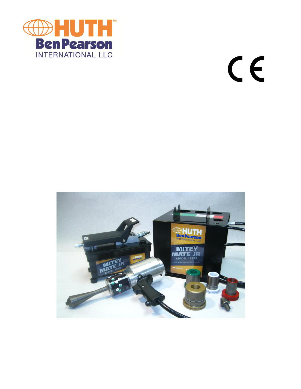
Model 1685S Tube Expander
OPERATOR’S MANUAL
ORIGINAL INSTRUCTIONS
MITEY MATE JR EXPANDER

TO THE OWNER
Please take a few minutes to carefully read this Operator’s Manual. It has been designed to
assist you in realizing the many benefits you anticipated when you purchased your Huth Tube
Expander. Every Huth Tube Expander is constructed from the finest materials by highly trained,
experienced craftsmen. They have a profound interest in your expander’s successful
performance and have prepared this manual to give you the benefit of their experience, gained
through years of building top-quality expanders and related products.
The manner in which you operate and the care you provide this expander will have a direct
bearing on its continued successful performance. Read this entire manual, keep it handy for
future reference.
It has always been Huth’s policy to improve its products whenever possible and practical to do
so. We reserve the right to make changes and/or improvements without incurring any
obligation to do so on previously sold products.
Fill in for easy reference:
Model H1685S
Serial Number_________________________
Date Delivered________________________
HUTH-BEN PEARSON INTERNATIONAL, LLC
260 GRANT ST.
P O BOX 270467
HARTFORD, WI 53027
800-558-7808
WWW.HUTHBENDERS.COM
Copyright 2015 – Huth – Ben Pearson International, LLC
1
WARNING!
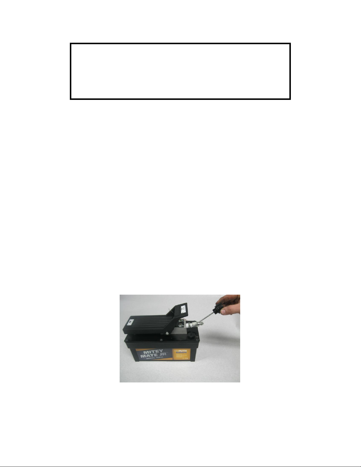
This pump must always be vented prior to using.
The vent cap/dip stick is the primary means to vent the
reservoir. It is attached to the pump when you receive
the unit. The vent cap/dip stick must be installed in the
pump before activation. The pump was shipped with a
temporary hex plug in the reservoir. It is located in the
front right corner of the reservoir. Remove the hex plug
and replace it with the vent cap/dip stick. Do not over
tighten the vent cap/dip stick.
The below picture shows the dipstick, which is pointing
toward the temporary hex plug that it should replace.
VENTING:
2

UPON DELIVERY
WEAR EYE PROTECTION
1. Read manual before proceeding.
2. Inspect for shipping damage or shortages.
3. Replace shipping plug with vent cap/dip stick. See page 2
4. Install the air regulator to the air intake port of the pump.
*Note: the air regulator is preset from the factory*
5. Select and install the threaded fitting that is compatible with your air
supply fittings. The air supply should be 80 PSI to 100 PSI to obtain the
rated hydraulic output. Air pressure should be regulated to a
maximum of 125 PSI.
6. Attach the Gun Head hydraulic hose to the pump.
7. Inspect that the arbor is firmly secured to the gun head.
8. Plug your air line into the pump. Air pressure should be regulated to a
maximum of 125 PSI.
9. Depress the foot pedal on the pump. The arbor will move inward.
10. Release the arbor by rocking the foot pedal forward. The arbor will
extend to its original position.
11. Your expander is now tested and ready for use. Continue to read page
6 for Operation Use.
3

SAFETY PRECAUTIONS
WARNING!
GENERAL OPERATION
1. All WARNING statements must be carefully observed to help prevent
personal injury.
2. Wear eye protection at all times.
3. Before operating this pump, the hose connections must be tightened
securely and leak free. Use the proper size wrenches when tightening. DO
NOT OVER TIGHTEN. Over tightening can cause premature thread failure
or high pressure fittings to split at pressures lower than their rating.
4. Should a hydraulic hose ever rupture, burst, or need to be disconnected,
immediately shut off the pump by shifting the foot pedal forward twice to
release pressure. Never attempt to grasp a leaking pressurized hose with
your hands. The force of escaping hydraulic fluid could cause serious
injury.
5. Do not subject the hose to potential hazards such as fire, sharp surfaces,
extreme heat or cold or heavy impact. Do not allow the hose to kink,
twist, curl, or bend so tightly that the oil flow within the hose is blocked
or reduced. Periodically inspect the hose for wear. Any of these
conditions can cause damage to the hose and possibly result in personal
injury.
6. Do not use the hose to move attached equipment. Stress can damage the
hose and possibly cause personal injury.
7. Hose material and coupler seals must be compatible with the hydraulic
fluid used. Hoses also must not come in contact with corrosive materials
such as creosote-impregnated objects and some paints. NEVER paint the
hose. NEVER paint the couplers. Hose deterioration due to corrosive
materials can result in personal injury.
4

PUMP
1. Do not exceed the PSI hydraulic pressure rating noted on the pump name
plate, 3,000, or tamper with the internal high pressure relief valve.
Creating pressure beyond rated capacities can result in personal injury.
2. Before replenishing the oil level, retract the system to prevent overfilling
the pump reservoir. An over fill can cause personal injury due to excess
reservoir pressure created when cylinders are retracted.
CYLINDER
1. Do not exceed the rated capacity of the cylinder. Excess pressure can
result in personal injury.
2. Do not set poorly balanced or off center loads on the cylinder. Uneven
pressure can result in damaged or broken parts. The load can tip and
cause personal injury.
AIR SUPPLY
1. Shut off and disconnect the air supply when the pump is not in use or
before breaking, disconnecting any connection in the system.
5

OPERATION USE
WEAR EYE PROTECTION
1. Be sure the arbor is fully secured to the gun head shaft.
2. Before operating machine, keep hands and fingers clear of pinch points.
3. Select the segment set according to the color code expanding chart on the housing.
4. Select the correct arbor tip that matches the segment set according to the color chart
on the housing. The small tip is only used with the small red segment set.
5. Install the correct tip on the arbor. Tighten the tip to the arbor with a wrench and light
pressure.
6. Install the selected segment set over the arbor by pressing the center of the opening
over the arbor tip and arbor.
7. Lubricate the arbor and face of the adjustable collar of the gun head where the base
of the segment set rides across it.
8. Select the desired expanding size by rotating the adjustable collar of the gun head
until the desired number setting is displayed in the indicator hole of the sight.
9. Holding the gun head firmly by the grip handle, place the segment set into the tube.
Depress the foot pedal of the pump until the tube expands slightly. This operation
helps remove any burrs on the tube end.
10. Release the foot pedal allowing the segment set to relax. Slightly rotate the segment
set and depress the foot pedal. Expand the tube halfway to the desired diameter.
11. Release the foot pedal and slightly rotate the segment set to expand the tube area
that was not expanded in the last operation. Continue until the desired diameter is
reached. The pump tone will change when maximum expansion is reached.
12. Release the foot pedal, slightly rotate the segment set, depress the foot pedal and
expand to round out the expansion.
6

MAINTENANCE
TOOLING: it is absolutely necessary to keep the arbor and expanding
segment sets clean and lubricated at all times. Many types of lubrication
may be used. Any lubrication, such as a grease type, may require cleaning
more often as burrs will be held in the lubrication. If expanding tools
become stuck in the tube this may be due to debris in the lubrication. To
remove the tooling from the tube, relax the tooling and slightly tap the
tube toward the gun head.
NEVER TRY TO FORCE STUCK TOOLING BY HAMMERING ON THE
GUN HEAD.
Tools should be stored carefully: clean and lubricated in the proper
location of the housing provided. Mishandling or abuse can result in
damage or breakage. Abuse of tooling or other parts will void the
warranty.
RESERVOIR: The reservoir should be checked for oil level occasionally.
The vent cap/dip stick is removed. The dip stick has two notches on it. The
oil level should never go below the bottom notch. Never fill the reservoir
above the top notch. Any I.S.O. Grade 46 hydraulic oil may be used. `
PRIMING THE PUMP UNIT
If the pump must be primed, use the following procedure.
1. Press the release end of the pedal while holding down the air intake
valve with a flathead screwdriver. The air intake valve is located
directly under the pedal at the air supply end of the pump. The valve is
depressed simultaneously with the release end of the foot pedal
during priming.
2. Allow the pump to cycle approximately 15 seconds.
7

3. Remove the screw driver, and depress the pump end of the pedal once
more.
4. If the ram retracts or pressure is built, the pump has been successfully
primed. If the pump does not respond, repeat the procedure. Jogging
the air intake valve while holding down the pedal in the release
position.
8

TROUBLE SHOOTING GUIDE
Pump reciprocates but
no oil delivered.
(ram does not retract)
1. Low oil level
2. Pump not primed
1. Replenish oil reservoir
2. See “Priming The Pump
Unit” page 7
Low oil delivery
(ram retracts slowly)
1. Inadequate air
supply
2. Hydraulic failure
1. Check air input supply. Set
at 80 PSI minimum.
2. Contamination. Check air
supply of pump. Clean
Pump will not build to
maximum pressure.
(no visible leaks)
Check the air supply
80 to 100 PSI required to build
maximum pressure.
Pump builds pressure
but will not hold
system pressure.
Check hydraulic
connections
Tighten and seal as needed
PROBLEM CAUSE SOLUTION
9

MODEL 1685S HAND HELD CYLINDER
1. 98124 Calibration Decal
2. 497 Arbor
3. 498 Small Arbor Tip
499 Large Arbor Tip
4. 595 Selector Sight
5. 92156 Cylinder
(Complete)
92167 Seal Kit for 92156
6. 97177 Pistol Grip Handle
7. 92258 Hose Assembly
MODEL 1685S POWER UNIT
1. 1612 Air/Oil Pump
2. 92072 3/8 NPT x ¼ NPT Hex Nut
3. 92364 Quick Disconnect Coupling
4. 97264 ¼ Pipe Nipple
5. 92162 Air Regulator
6. 92163 1/8 Pipe Plug
10

WARRANTY
This warranty is made for the exclusive benefit of the original owner and is not
transferable. There is no other warranty applicable to Huth-Ben Pearson
products, and no representative has any authority to make representation,
promise or agreement except as stated in the warranty.
ONE YEAR WARRANTY
For one year from the date of original invoice the SELLER will repair the
expander if found to be defective in material and workmanship without cost to
the purchaser. Following the first 90 days from the date of original invoice,
Replacement Parts are shipped from the SELLER to the Purchaser freight collect.
Return of defective parts are shipped prepaid to the SELLER.
In affecting such repairs, the SELLER may at its election, repair or replace any
parts which it finds to be defective.
Tools and dies are warranted for a period of 90 DAYS against defects in material
and workmanship.
DURING THE FIRST 90 DAYS FROM DATE OF ORIGINAL INVOICE THE SELLER
WILL PAY FREIGHT CHARGES FOR REPLACEMENT OF DEFECTIVE PARTS.
11
 Loading...