


RGB ELEKTRONIKA AGACIAK CIACIEK
SPÓŁKA JAWNA
Jana Dlugosza 2-6 Street
51-162 Wrocław
Poland
biuro@rgbelektronika.pl
+48 71 325 15 05
www.rgbautomatyka.pl
www.rgbelektronika.pl
DATASHEET
www.rgbautomatyka.pl
www.rgbelektronika.pl
OTHER SYMBOLS:
CNC-H6DL-B3
CNCH6DLB3, CNCH6DL B3, CNCH6DL-B3, CNC H6DLB3, CNC H6DL B3, CNC H6DL-B3, CNC-H6DLB3,
CNC-H6DL B3, CNC-H6DL-B3
HUST

YOUR
PARTNER IN
MAINTENANCE
At our premises in Wrocław, we have a fully equipped servicing facility. Here we perform all the repair
works and test each later sold unit. Our trained employees, equipped with a wide variety of tools and
having several testing stands at their disposal, are a guarantee of the highest quality service.
OUR SERVICES
ENCODERS
SERVO
DRIVERS
LINEAR
ENCODERS
SERVO AMPLIFIERS
CNC
MACHINES
MOTORS
POWER
SUPPLIERS
OPERATOR
PANELS
CNC
CONTROLS
INDUSTRIAL
COMPUTERS
PLC
SYSTEMS
Repair this product with RGB ELEKTRONIKA
ORDER A DIAGNOSIS
∠
Buy this product at RGB AUTOMATYKA
BUY
∠

BENDING MACHINE
OPERATION MANUAL
H6D-B 3-AXIS
2012-12
HUST Automation Inc.
No. 80 Industry Rd., Toufen, Miaoli, Taiwan
Tel: 886 37 623242 Fax: 886 37 623241


Contents
i
Contents:
1. Non Mode Page 1
2. AUTO mode (main page)
3
3. File setting page
6
4. MCM(Vice)setting page
8
5. Editing mode
10
6. The main page of program number selection
11
7. Bending-selection for fold setting page
13
8. JOG mode
16
9. HOME mode
18
10. Error and Absolve
19
11. Graph for reference(Graph)
21
12. Bending Machine I/O List
22
13. Machine Connection Diagram
25
Appendix 1、 Emergent Stop Connection Diagram
28
Appendix 2、 Servo Driver Servo-On Connection Diagram
29
Appendix 3、 H6D-B Controller size
30
Appendix 4、 Bending Angle Conception
32
Appendix 5、 H6D-B Control Structure of Bending Machine
33
Appendix 6、 MCM (Parameter)
34
Appendix 7、 Sanyo Servo Machinery Connection
66
Appendix 8、 Mitsubishi Servo Machinery Connection
67
Appendix 9、 Servo Motor And MPG Connection
68
Appendix 10、 Install Manual
69
H6D-B LCD flow-process diagram
74
Appendix 11、 ERROR MESSAGES
75
Appendix 12、 USB Operation instructions
79
Appendix 13、 BL-Compensation Operation instructions
81

HUST CNC H6D-B3 MANUAL
ii

HUST CNC H6D-B3 MANUAL
1
When the controller is power on it will download some data. So do not operate
the controller till the download operation finished.
Fig 1
1. Non Mode Page (Freedom editor)
Fig 2
開機資料處理中
Data Loading
請稍候……..
Please Wait……
億圖實業股份有限公司
H
H
U
U
S
S
T
T
C
C
N
N
C
C
TEL:886-37-623242
FAX:886-37-623241
e-mail:hust@ms14.hinet.net
HUST CNC H6D-B3 MANUAL
2
Fig 3
Caution !!! When the power is reopened, plz execute 3 Axes to
home
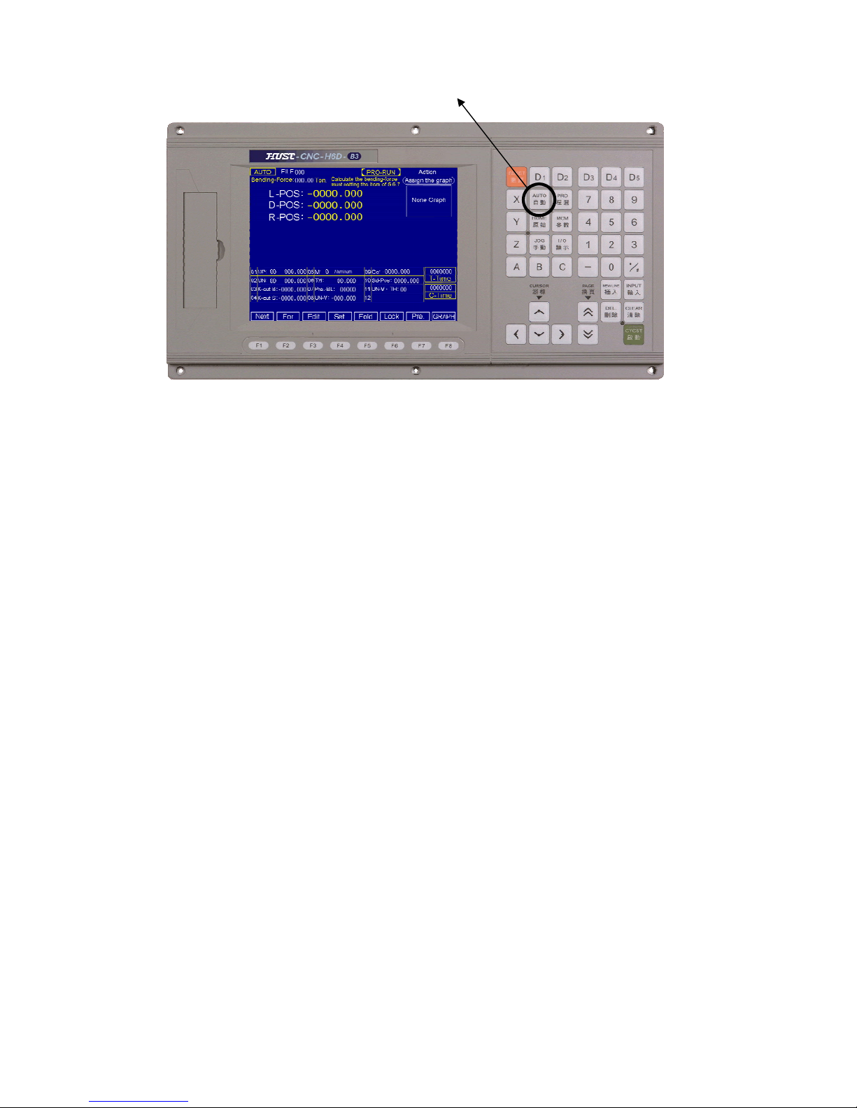
To main page : Press “AUTO” on the key board
HUST CNC H6D-B3 MANUAL
3
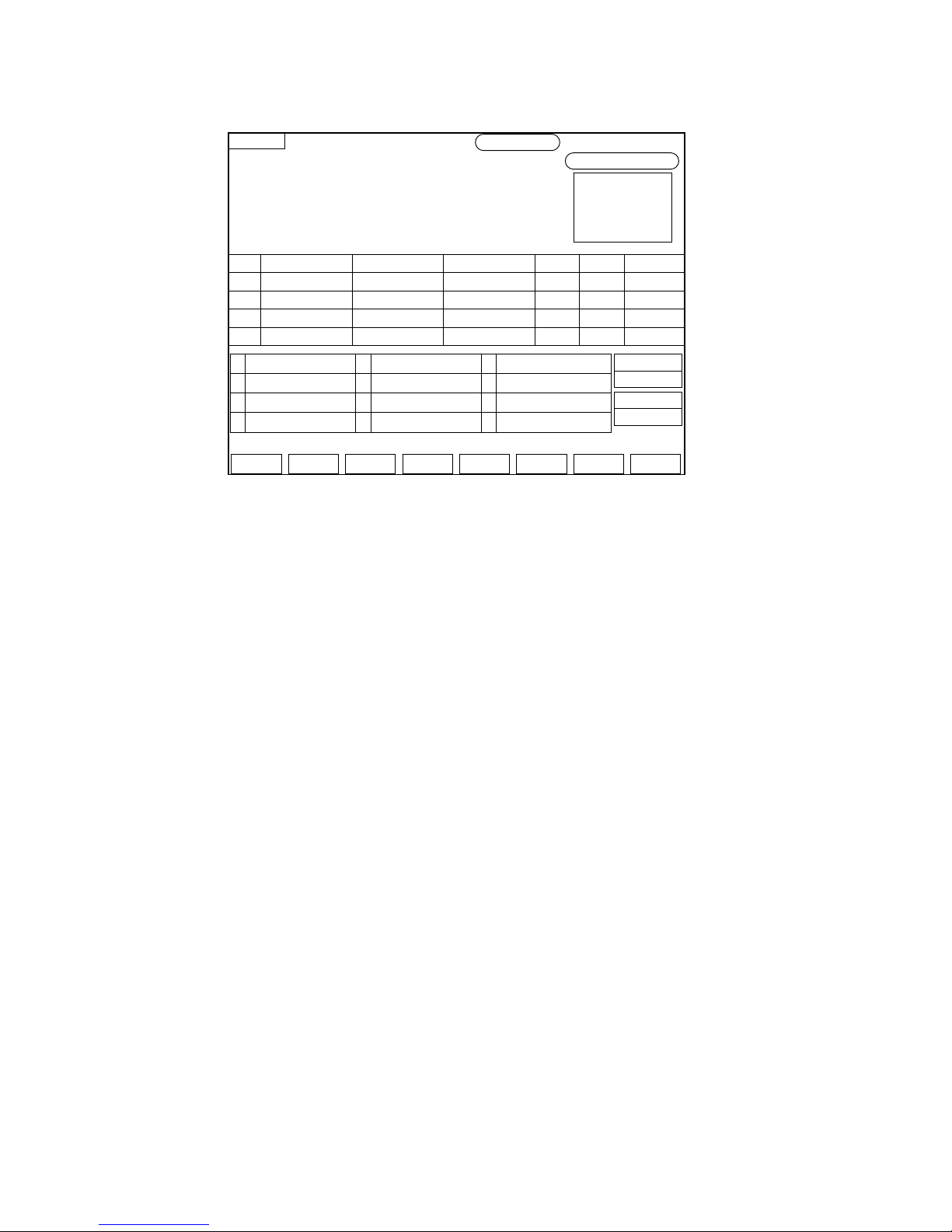
2. AUTO mode : (main page)
Fig 4
(1) Function key:
a. CYCST:Cycle start
(a) Press this key to run the program.
(b) When the program is running, the LED-light located left-up of the
CYCST will be on. Then the number of piece bended will begin to be
counted.
b. RESET:
CNC gives an order to controller that let it stay on the non-mode, and the
frame jumps to the non-mode page.
c. Edit :
When pressing this key on any mode, the controller will execute RESET first.
Let the controller stay on non-mode status and then jump to the file-set page.
d. Set:
When pressing this key on any mode, this key will highlight. It means that the
controller is not running any program. And use CURSOR key to set the value
of Total-Cor.(Gα), SD-Pos., Total-number(T-Time) 【Material】、【Depth】、
【Pre.-BL】and Count number(C-Time).
e. FORWARD : Execute last program
Do not press the NEXT key again when the white light is not canceled.
Because the program is not running over.
f. NEXT : Execute next program
Do not press the FORWARD key again when the white light is not canceled.
Because the program is not running over
g. Lock:
AUTO
Next For Edit Set Lock Pre. GRAPH
PRO-RUN
FILE000
Bendin
g
-Force:000.00 Ton.
Calculate the bending-force
must settin
g
the item of 5.6.7
L-POS :-0000.000
D-POS :-0000.000
R-POS :-0000.000
Assign the graph
Adtion
None Graph
01 UP:00 000.000
05
M: 0 Aluminum 09C: -0000.000
02 UN:00 000.000 06 TH: 00.000 10Sd-Pos: 0000.000
03
K-out B:-0000.000
07
Pre.-BL: 00000 11UN-V、TH:00
04 K-out S:-0000.000 08 UN-V: -000.000 12
0000000
T-Time
0000000
C-Time
N X
R
Vic e BL C
00 0000.00 -000.00 000.00 00 0000 -00.00

HUST CNC H6D-B3 MANUAL
4
When pressing this key, the running program will stop at this step.
※ Press again to cancel.
h. Pre.-BL
Calculate the Bending-Force must be setting the item of 5,6,8.
i. Graph for reference(Graph)
Push this key and enter Graph for reference and establish pages.
(2) Additional description : When the setting key is highlight:
a. Total correction(Gα):
Programs in the file are all corrected When trying to bending 90 degree, the
angle is not enough : Set value positive too deep : Set negative value
EX 1 :
(a) The Y-axis(D-axis)movement of one unit is set as 0.01 ( P-αD = 0.01 ).
Set in the mode of Edit-FOLD-UN-SET.
(b) Gα= 5.000 ( total correction )
(c) The unit of the total correction is
P-αD × Gα÷ 1000 = 0.010 × 5000 ÷ 1000 = 0.05 mm
EX 2 :
(a) The Y-axis(D-axis)movement of one unit is set as 0.04 ( P-αD = 0.04 ).
Set in the mode of Edit-FOLD-UN-SET.
(b) Gα= 5.000 ( total correction )
(c) The unit of the total correction is
(d) d. P-αD × Gα÷ 1000 = 0.040 × 5000 ÷ 1000 = 0.2 mm
b. SD-position :
Input the location of angle-axis directly. Then press 【CYCST】key to execute
it. When the position is arrived, the number of D-axis will be canceled
automatically. At this time we can press【CYCST】key to run the program
directly.
c. T-Time :
Set total number of pieces
d. C-Time :
When it has run all the programs, the number will be added by 1 (Number of
piece)
e. Material:(Establish the range 0-2)
Establishment:0,Stainless steel 、1,Iron 、2,Aluminium
f. Pre.-BL
g. Calculate the Bending-Force condition needed
h. Thickness:
Input the Bending Machine of project
HUST CNC H6D-B3 MANUAL
5
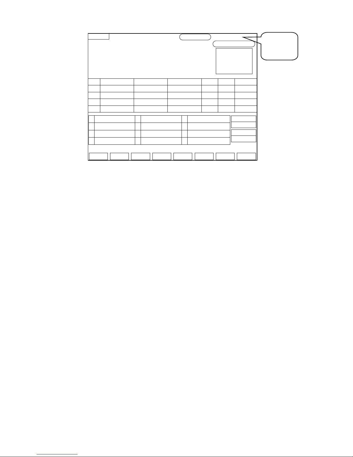
Fig 5
Display :
(1) Press RESET to the frame of non-mode.
(2) Status display
When the number of work pieces is up to the setting:
The MARK【Reaching-End】will highlight if the setting value is not equal to 0
OR current number is > or = the setting number.
a. K-OUT ≦
b. UP-H ≦ 0
c. UN-H ≦ 0
d. UN-V ≦ 0
e. TH ≦ 0
※When status is shown, it can not be operated by controller.
(3) L-axis :(X-coordinate)
Show the position of L-axis right now.
(4) D-axis :(Y-coordinate)
Show the position of D-axis right now
(5) R-axis :(Z-coordinate)
Show the position of R-axis right now
a. Show the bend song pressure number value of this project.
b. In the project lasts:When projects are carried out , will show the white.
(6) Graph for reference(Graph)
Show this procedure chooses at present Graph for reference.
The situation
shows the
position
AUTO
Next For Edit Set Lock Pre. GRAPH
PRO-RUN
FILE000
Bendin
g
-Force:000.00 Ton.
Calculate the bending-force
must settin
g
the item of 5.6.7
L-POS :-0000.000
D-POS :-0000.000
R-POS :-0000.000
Assign the graph
Adtion
None Graph
01 UP:00 000.000
05
M: 0 Aluminum 09C: -0000.000
02 UN:00 000.000 06 TH: 00.000 10Sd-Pos: 0000.000
03
K-out B:-0000.000
07
Pre.-BL: 00000 11UN-V、TH:00
04 K-out S:-0000.000 08 UN-V: -000.000 12
0000000
T-Time
0000000
C-Time
N X
R
Vic e BL C
00 0000.00 -000.00 000.00 00 0000 -00.00

HUST CNC H6D-B3 MANUAL
6
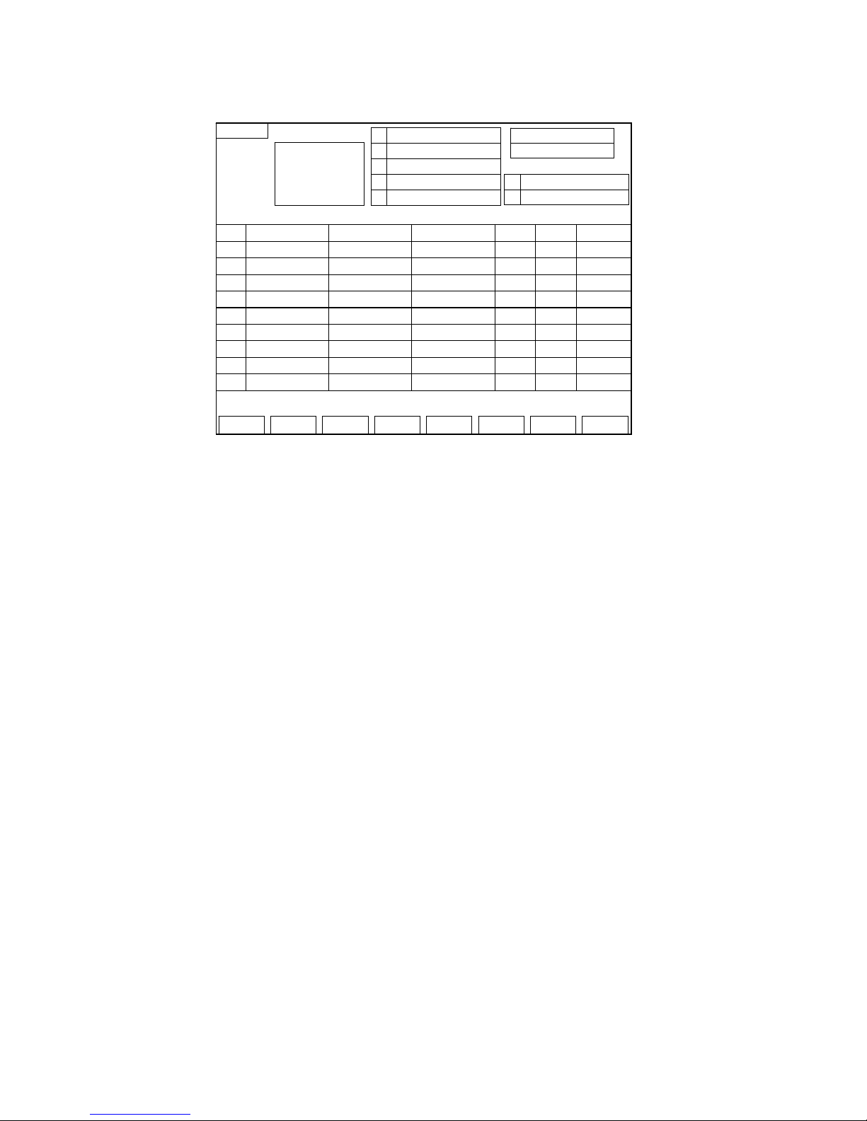
3. File setting page :
Fig 6
(1) 【Show】the maximum number of file can be set.
(2) After pushing the fast procedure options button, Press the number keys on the
keyboard directly. Input the number of file( Number will show up the INSERT
key.) When input the number of file and then press INPUT key, “data loading
please wait…” will show below. When it disappears , we can choose other
function key.
(3) After the number of file is set, please go to the page of BENDING-SELECTION
and TYPE-SET to enter correct data. Then we go to the EDIT page input
bending
(4) INSERT key:(Ins.)
Insert one line of blank program below current cursor.
(5) DELETE key:(Del.)
Delete the setting value of one line.
(6) Fold-Selection
Push this key and enter Fold-Selection and establish pages.
(7) MCM key:
Go to the PARAMETER setting page.
(8) BTO key:(Back To One)
Move the cursor back to the first node.
(9) Fast procedure options KEY:
After pushing this function key,Can do movements that the fast procedure
chooses.
(10) Graph for reference(Graph)
Push this key and enter Graph for reference and establish pages.
EDIT
Fold V.MCM BTO F.P ro -S GRAPH Del Graph Ret
None Graph
N X
R
Vic e BL C
00 0000.00 -000.00 000.00 00 0000 -00.00
Set-File:0500
File:000
K-Out B:-0000.000
K-Out S:-0000.000
06
07
M : Aluminum
TH: 00.000
01
02
UP :00 0000.000
UN:00 0000.000
03
04
V : -000.00005

HUST CNC H6D-B3 MANUAL
7
(11) Graph delete(Del.-Graph)
After pushing this function key, can delete the figure of all Graph for reference
of procedure.
(12) RET:BACK TO AUTO MODE
PS:
When the MCM setting value is 0, the program has no recycle and no DX. It ranges
from 0 to 10.
Ex : Function setting(Vice)
Value 1: The program will execute first motion by the MCM-setting page.
Value 2: The program will execute second motion by the MCM-setting page.
ETC…
HUST CNC H6D-B3 MANUAL
8
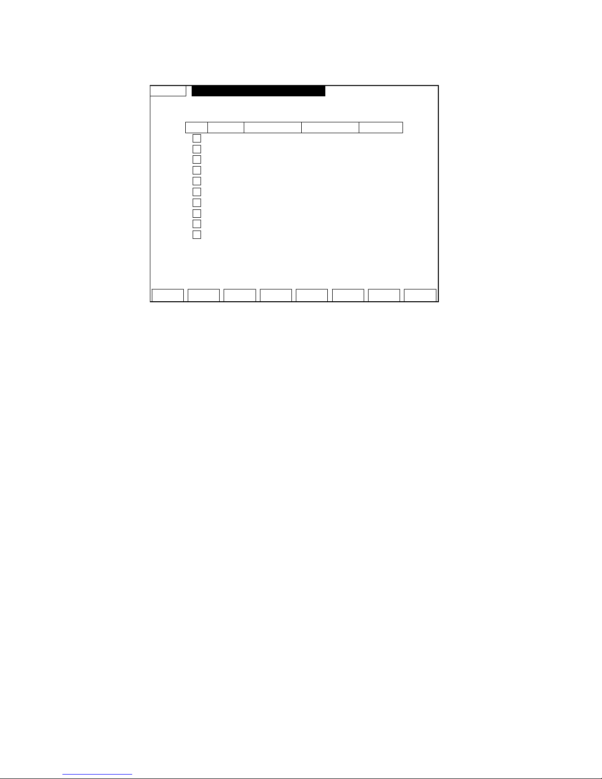
4. MCM(Vice)setting page:
Fig 7
(1) Cycle:(Cyc)
Square input-area number chosen
value 1 Successful recycle.【bending arc】
value 0 Failed recycle. Only run the distance of DX
※ By using this function you must set counter value as not zero. Or this
function will be useless.
(2) Delay Time:(Time) Range from 0 to 9.9s
Cycle setting value【1】: The pausing time is set as when executing cycle motion
for bending arc, there is a pausing time between each time bending.
(3) DX:
Set the distance of X-axis move out or cycle when bending.
(4) Count :
If the cycle setting value is 1, the program motion will proceed orderly by【Ran】
setting value.
Ex : If the【Ran】 value is 3mm,【count】value is 10 , X-axis will proceed 3mm
and repeat 10 times. And each time will proceed after I007 signal changes on to
off.
Attention :
When the cycle setting value is 1 , we must notice that if the total distance of cycle
will be over X initial coordinate.【between X difference and keep-out setting】If it
dose, system will adjust cycle value automatically.
EX:
Vice Cyc Time Ran Count
01
0 00.0 -000.000 0000
02
0 00.0 -000.000 0000
03
0 00.0 -000.000 0000
04
0 00.0 -000.000 0000
05
0 00.0 -000.000 0000
06
0 00.0 -000.000 0000
07
0 00.0 -000.000 0000
08
0 00.0 -000.000 0000
09
0 00.0 -000.000 0000
10
0 00.0 -000.000 0000
VMCM
Ret
Prarmeter Setting 1~10
HUST CNC H6D-B3 MANUAL
9
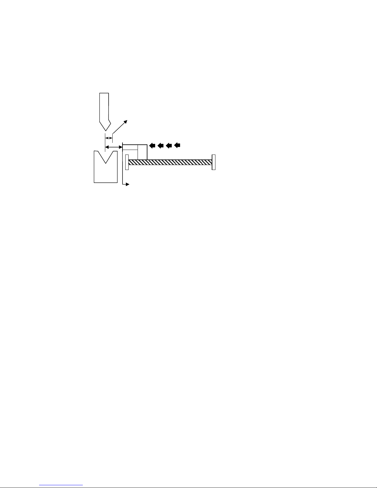
Set value of cycle to 1,【Ran】to 3, 【count】 to 10, X initial coordinate to 20.000,
keep-out area to 7.9, System will adjust it to 4 times automatically.
3×10=30
20-7.9=12.1
30>12.1,【count】value will turn to 4 automatically.
Fig 8
X initial coordinate is 20.000
keep-out area is
【count】value will turn to 4
automaticall
y
HUST CNC H6D-B3 MANUAL
10
5. Editing mode
Fig 9
(1) Press the CURSOR key to move to the column to be input. Then input the value.
(2) When the cursor is located on the last line of program, by pressing the
cursor-down key the controller will insert one blank program line automatically.
If you are not going to use this blank program line, please press the DELETE
key to delete this blank program.
(3) If you want to set the value as “BLANK”, you can press the CLEAR key first
and then press the INPUT key. The setting column will be on the blank status.
EDIT
Fold V.MCM BTO F.P ro -S GRAPH Del Graph Ret
None Graph
N X
R
Vic e BL C
00 0000.00 -000.00 000.00 00 0000 -00.00
Set-File:0400
File:000
K-Out B:-0000.000
K-Out S:-0000.000
06
07
M : Aluminum
TH: 00.000
01
02
UP :00 0000.000
UN:00 0000.000
03
04
V : -000.00005
HUST CNC H6D-B3 MANUAL
11
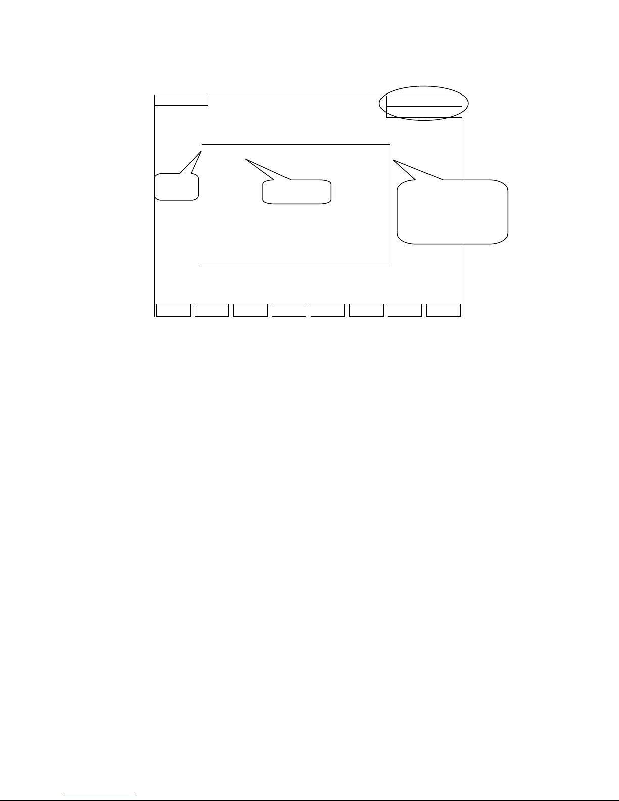
6. The main page of program number selection
Fig 10
(1) Press【PAG E】or【CURSOR】key to move the cursor.
(2) 【Ret】key:back to the File setting page.
(3) 【COPY】key:go to the PRO-COPY page.
(4) Move to the set number then press the SELECT【SEL】key.
(5) Editor key:After choosing the procedure,to editor's page editor's procedure.
(6) Group number after altering,Show above right of the screen.
The cursor stays on the position of O000 ,The group shows it is 0, If the cursor
is moved to O004, The group shows it is 4 after pushing the options button.
(7) 【DELETE【Del】key: When you are trying to delete the program number the
cursor pointing at, the confirming line will be shown as the picture below
Press【Y】:Delete the content of the program.
Press【N】:Back to the former page.
※ After finishing carrying out movements , get back to the procedure and choose the
page。
Annotation
SEL-FILE
DEL Copy Select
Ret
Set-File:0400
000
SOURCE 000 TARGET 000
> O000 EMPTY
O001 EMPTY
O002 EMPTY
O003 EMPTY
O004 EMPTY
O006 EMPTY
O007 EMPTY
O008 EMPTY
O009 EMPTY
CURSOR
EMPTY The
representative is an
empty procedure.
HUST CNC H6D-B3 MANUAL
12
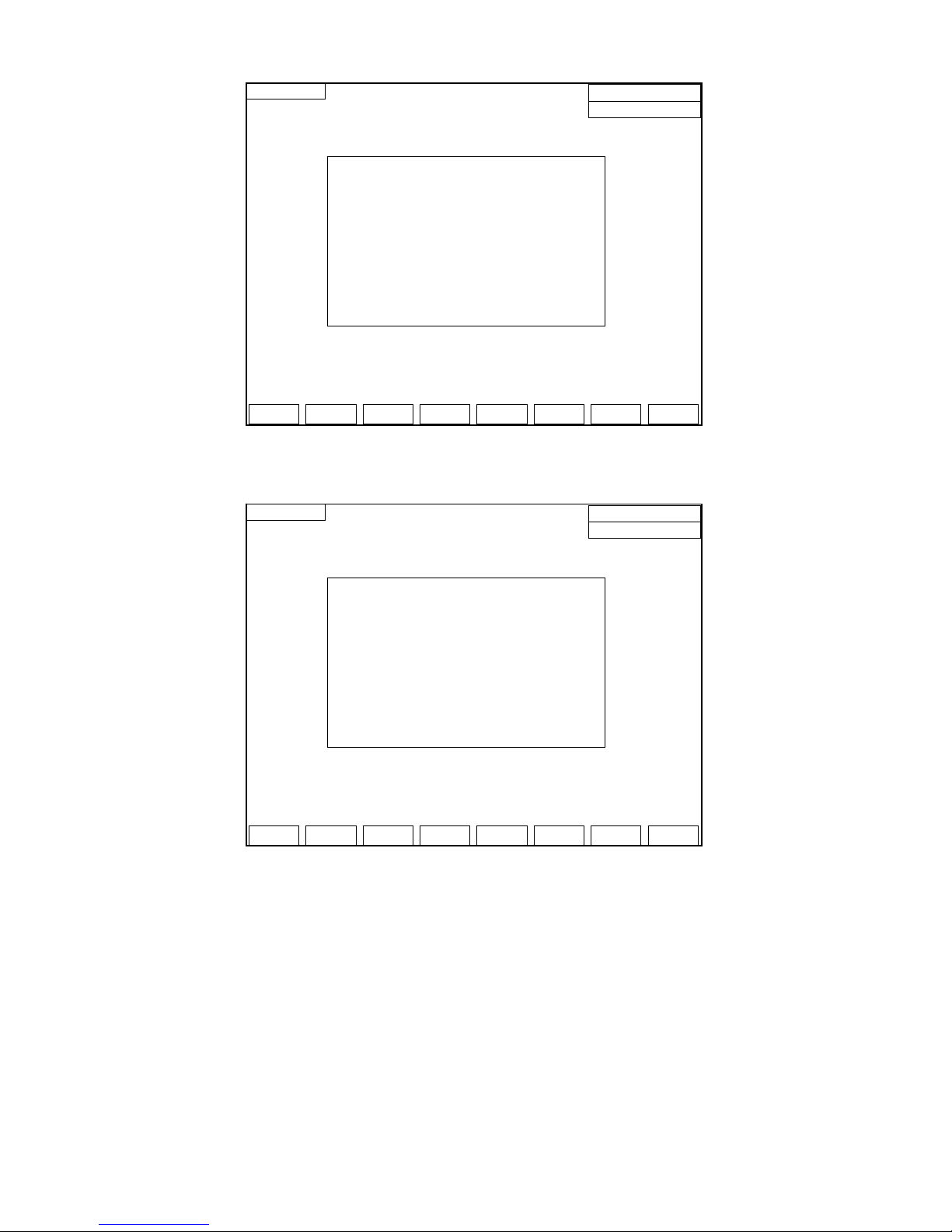
Fig 11
※ The program-copy page
Fig 12
(1) Move the cursor to the program number to be copied and press the【SOURCE】
key.
(2) Then move the cursor to the program number to be placed and press the
【TARGE T】key.
(3) Press the【COPY】key. The operation of copying program will be executed.
EX:A group and 0 (O000) copy 5 to the group (O005)
a. The cursor is moved to “Source” Group (O000) Press down the Source
key。
b. The cursor is moved to “Purpose” Group (O005) Press down the
Purpose key。
SEL-FILE
DEL Copy Select
Ret
Set-File:0500
000
SOURCE 000 TARGET 000
> O000 EMPTY
O001 EMPTY
O002 EMPTY
O003 EMPTY
O004 EMPTY
O006 EMPTY
O007 EMPTY
O008 EMPTY
O009 EMPTY
SEL-FILE
YES
N
O
Set-File:0400
000
SOURCE 000 TARGET 000
> O000 EMPTY
O001 EMPTY
O002 EMPTY
O003 EMPTY
O004 EMPTY
O006 EMPTY
O007 EMPTY
O008 EMPTY
O009 EMPTY
HUST CNC H6D-B3 MANUAL
13
c. Will show at this moment【0 groups copy to 5】。
d. Push and copy the key, Can finish copying movements.
(4) Press the enter key and get back to the automatic way page.
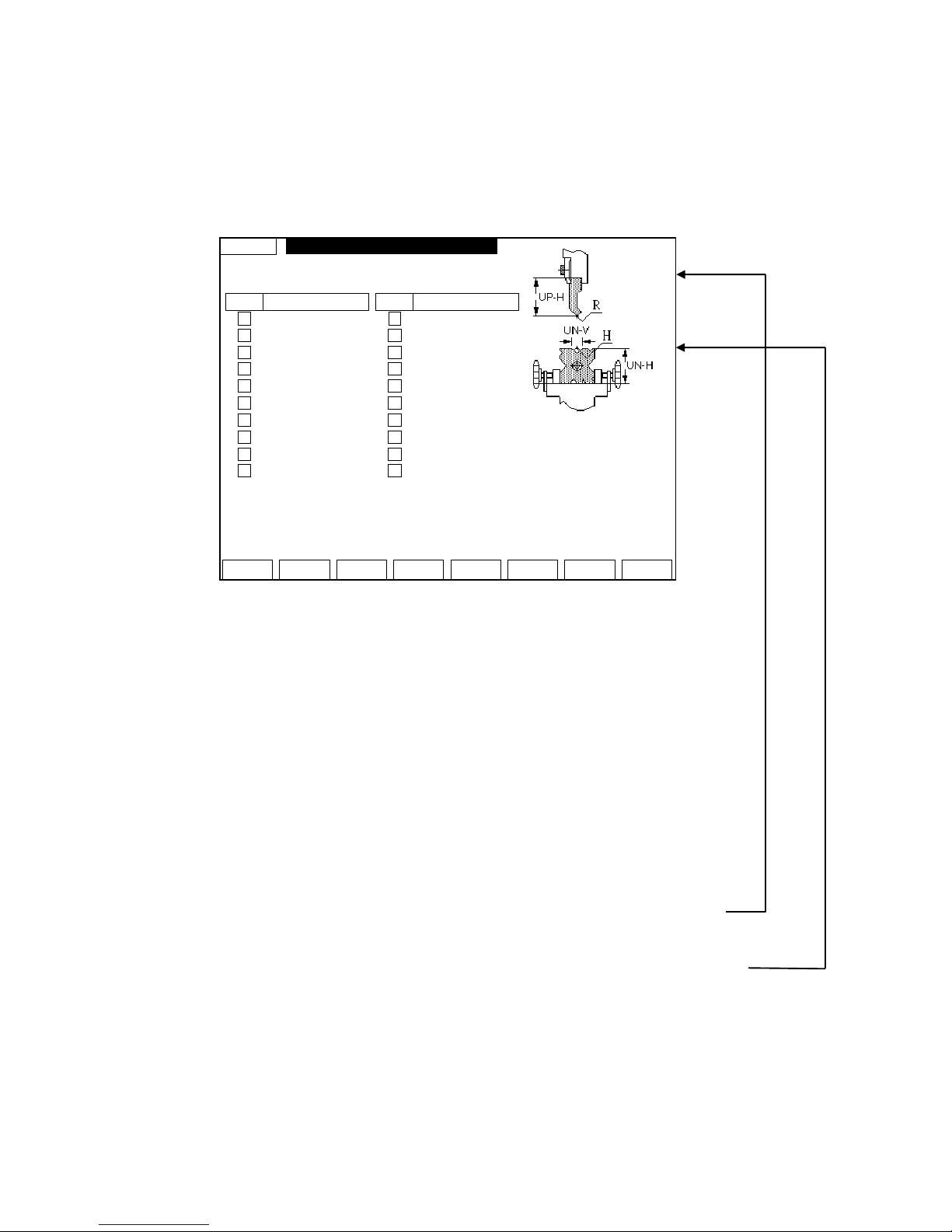
7. Bending-selection for fold setting page :(FOLD)
Fig 13
(1) Upper-CHICE number :(UP)
Input the serial number of upper- CHICE
(2) UNIT- CHICE number :(UN)
Input the serial number of unit- CHICE
(3) UP-SET :
Total file setting of UP-SET is 20.
Function key:
(UN)Lower:Establish pages to make the(UN) Lower.
Editor:To editor's page.
Turn back:Get back to the automatic way.
Display:
Ones that show and choose at present specification of the cutter。
(UP) Upper and(UN)Lower Choice the structure chart,Can establish the
specifications of a knife of tools according to the sign of the figure .
(UP) Upper-Choice page:(Can establish the height , width of cannelure ,
SMALL K-OUT setting、BIG K-OUT setting.)
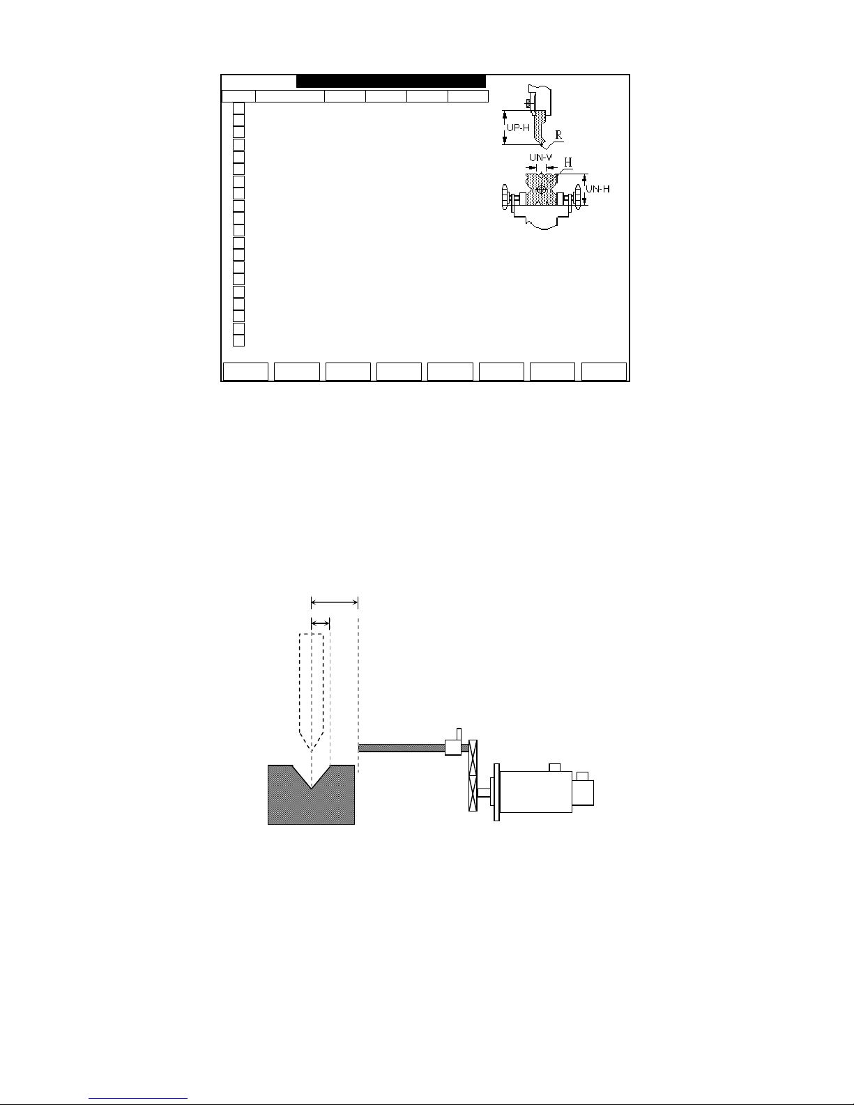
(4) UN-SET :
Total file setting of UN-SET is40
UP UP-H
01
0000.000
02
0000.000
03
0000.000
04
0000.000
05
0000.000
06
0000.000
07
0000.000
08
0000.000
09
0000.000
10
0000.000
Fold
UN-Set Edit Ret
Upper-Choice 1~20/Lower-Choice 1~40
Tool Use
d
UP-H : 000.000
UN-H : 000.000
UN-V : 00.000
K-Out B : 000.000
K-Out S : 000.000
Instruction
UP UP-H
11
0000.000
12
0000.000
13
0000.000
14
0000.000
15
0000.000
16
0000.000
17
0000.000
18
0000.000
19
0000.000
20
0000.000
UP-SET:00
HUST CNC H6D-B3 MANUAL
14
Fig 14
The upper-highness(UP-H)、unit- highness(UN-H)and unit-vice(UN-V)will show
up after the value of upper and unit setting.
PS1:The upper file and UNIT file can match each other freely
PS2:1:SMALL K-OUT setting.
2:BIG K-OUT setting
※ It must be careful to setting the K-OUT value.
Fig 15
Function key:
(UN) Lower:Establish pages to make the (UN) Lower.
Editor:To editor's page.
Turn back:Get back to the automatic way.
UP (DOWN) page:Switch over the UP(DOWN) page of establishing.
Display:
UN UN-H UN-V K-Out SK-Out B P-D
01
0000.000 00.000 00.000 00.000 00.000
02
0000.000 00.000 00.000 00.000 00.000
03
0000.000 00.000 00.000 00.000 00.000
04
0000.000 00.000 00.000 00.000 00.000
05
0000.000 00.000 00.000 00.000 00.000
06
0000.000 00.000 00.000 00.000 00.000
07
0000.000 00.000 00.000 00.000 00.000
08
0000.000 00.000 00.000 00.000 00.000
09
0000.000 00.000 00.000 00.000 00.000
10
0000.000 00.000 00.000 00.000 00.000
11
0000.000 00.000 00.000 00.000 00.000
12
0000.000 00.000 00.000 00.000 00.000
13
0000.000 00.000 00.000 00.000 00.000
14
0000.000 00.000 00.000 00.000 00.000
15
0000.000 00.000 00.000 00.000 00.000
16
0000.000 00.000 00.000 00.000 00.000
17
0000.000 00.000 00.000 00.000 00.000
18
0000.000 00.000 00.000 00.000 00.000
19
0000.000 00.000 00.000 00.000 00.000
20
0000.000 00.000 00.000 00.000 00.000
UN-SET:00
UP-Set PAGE Edit Ret
Upper-Choice 1~20/Lower-Choice 1~40
Tool Use
d
UP-H : 000.000
UN-H : 000.000
UN-V : 00.000
K-Out B : 000.000
K-Out S : 000.000
Instruction
X(L)-axis
SEVRO
1
2

HUST CNC H6D-B3 MANUAL
15
Ones that show and choose at present specification of the cutter。
(UP) Upper and (UN) Lower Choice the structure chart,Can establish the
specifications of a knife of tools according to the sign of the figure .
HUST CNC H6D-B3 MANUAL
16
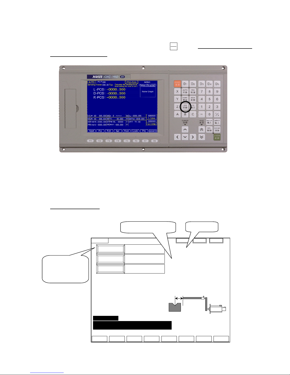
8. JOG mode:
(1) The page will move to JOG mode by pressing key. ( this key will fail when
the program is running)
Fig 16
(2) Choose axis value of JOG by MPG or choose it on the keyboard. When the
MPG is off, then the function on the keyboard is on.
L-axis(X)、D-axis(Y)
Parameter 22 = 0 :The function is on by MPG hand wheel.
Parameter 22 = 1 :JOG operation on the keyboard.
Setting by engineer
(3) Turn the “MPG” or press “PAGE” key Manual control
Fig 17
JOG
手動
JOG
Correct Enter Ret
L-POS
-0000.000
-0000
-0000.000
D-POS
-0000.000
-0000
-0000.000
Correct Step:
1. MPG or JOG mode, move the
L(X)-axis to suitable position.
2. Measure the actually value.
3. Input the Value.
4. Quickly press the ENTER key twice.
Then renew the coordinate.
5. After renew the coordinate then turn
to the JOG mode automatically.
R-POS
-0000.000
-0000
-0000.000
Setting coordinate
L:-0000.000
D:-0000.000
R:-0000.000
X1 X10 X100
Error Message:
Err56 The Z-axis(R-axis) negative way assign value
is smaller than the setting value.
Measuring value:-0000.000
Servo Error
Machinery coordinate
+ limit signal
HOME limit signal
- limit signal
HUST CNC H6D-B3 MANUAL
17
(4) After inputting assign point of each axis, by pressing the “M.T.C” key, the axis
will move to the assign coordinate.
When executing this operation, some error maybe occur:
Err 51:The X -axis(L-axis)positive way assign value is bigger than the setting
value.
Err 52:The X -axis(L-axis)negative way assign value is smaller than the
“Keep-Out” area value.
Err 53:The Y -axis(D-axis)positive way assign value is bigger than the setting
value.
Err 54:The Y -axis(D-axis)negative way assign value is smaller than the setting
value.
Err 55:The Z -axis(R-axis)positive way assign value is bigger than the setting
value.
Err 56:The Z -axis(R-axis)negative way assign value is smaller than the setting
value.
(5) DX:(add pressure limit)
When this function is on, it will highlight. When the DX signal(I007 = 1)is
coming in, the X-axis will do the operation of DX. The distance is based on the
VICE of the 10th group of EDIT MODE.
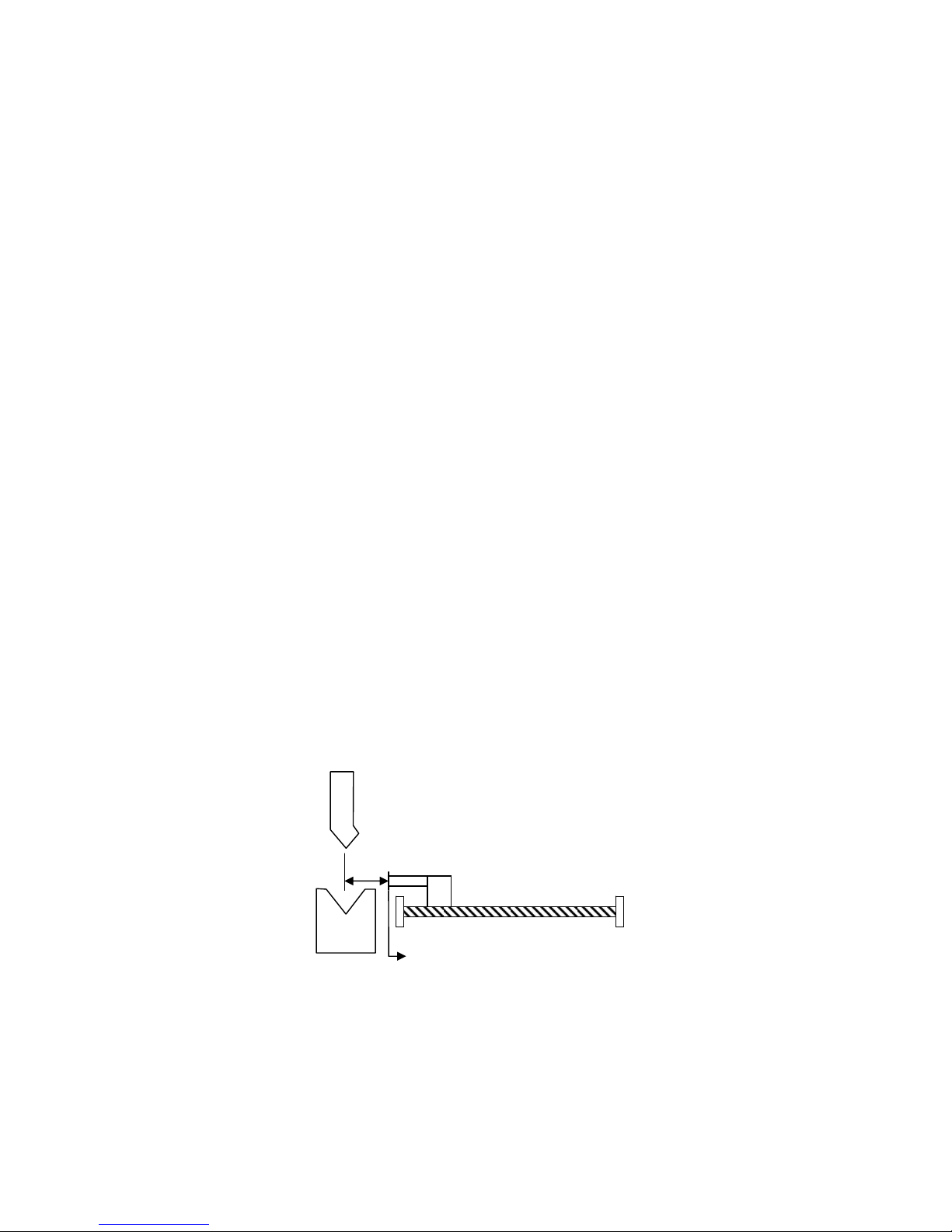
(6) Correct:【Just only L-axis(X)】
a. move the L-axis and measuring.
b. Enter the L-axis of measuring value。
c. Quickly press the ENTER key twice , then renew the coordinate.
d. After renew the coordinate then turn to the JOG mode automatically.
Fig 18
measuring
The actually range is 20.000 mm
HUST CNC H6D-B3 MANUAL
18
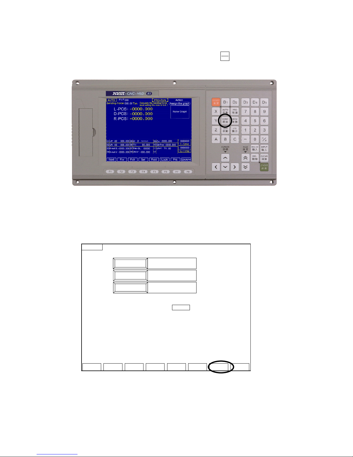
9. HOME mode
(1) It will move to the HOME-mode page by pressing key ( This key will fail
when the program is running.)
Fig 19
(2) Choose axis to home operation on the keyboard.
L-axis(X)、D-axis(Y)、R-axis(Z)
(3) Press CYCST key. Motor begins to execute the motion to HOME.
(4) After the motion done, press AUTO key to the main page.
Fig 20
HOME
L.D.R Ret
L-POS
-0000.000
-0000
-0000.000
D-POS
-0000.000
-0000
-0000.000
R-POS
-0000.000
-0000
-0000.000
INSTRUCTION:
1.When 3-Axis Move, Select L.D.R Key.
(They Must Not ON 0 Position.) or Select The
Axis on Key-Board.
2.Press Cycst Key.
HOME
原點
HUST CNC H6D-B3 MANUAL
19
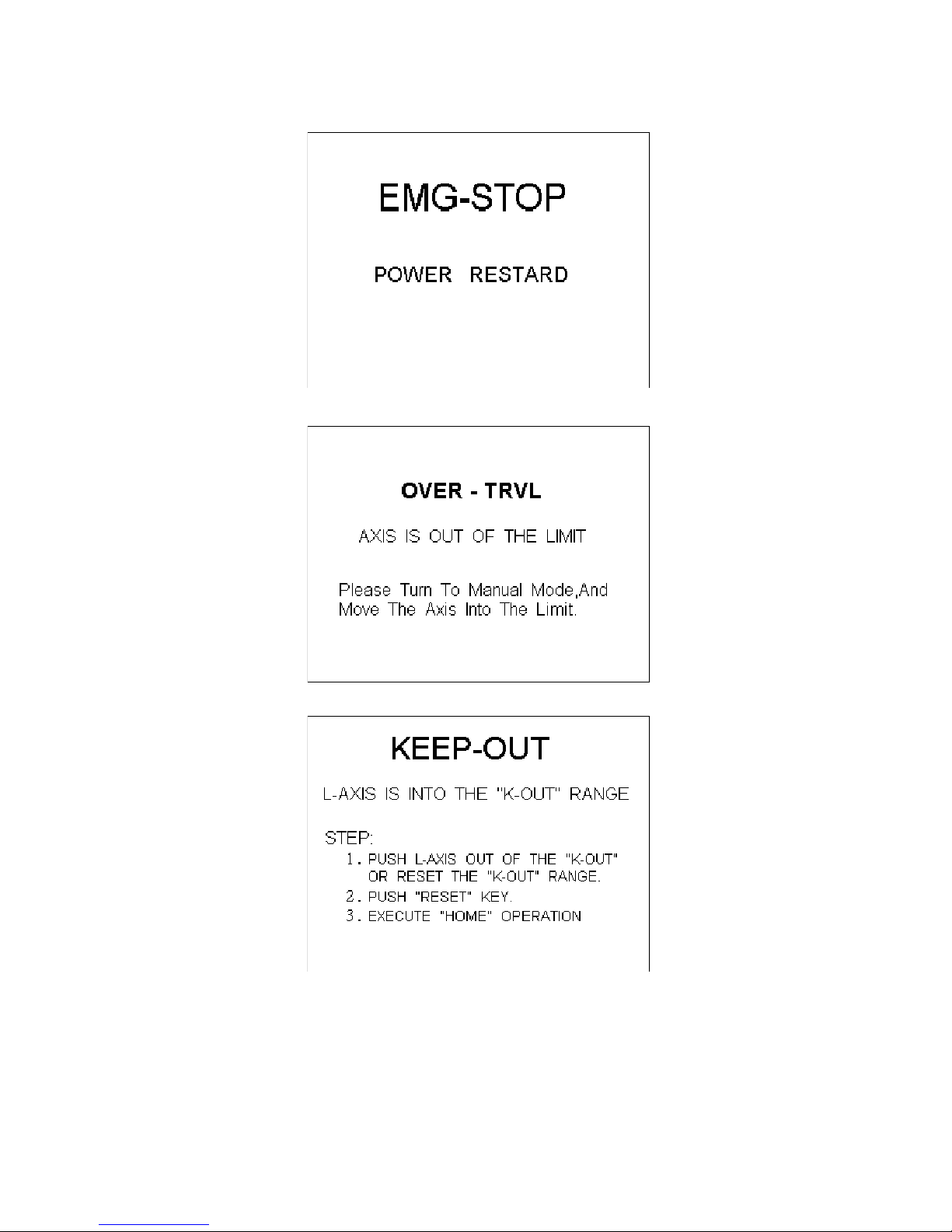
10. Error and Absolve (total Error page)
Fig 22
Fig 23
Fig 24

HUST CNC H6D-B3 MANUAL
20
Fig 25
Fig 26
HUST CNC H6D-B3 MANUAL
21
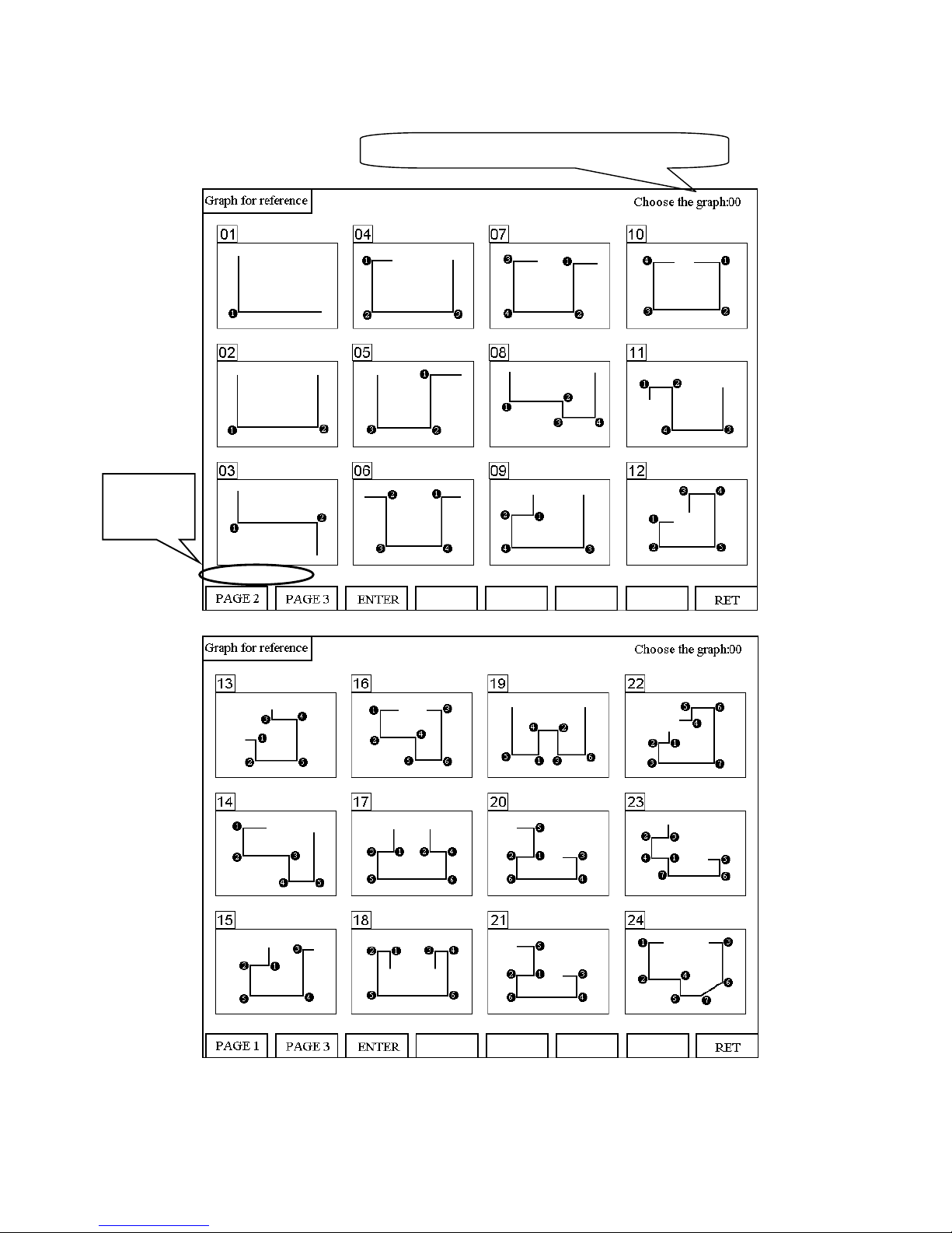
11. Graph for reference ( Graph )
Fig 27
Fig 28
Show that chooses the serial number of the figure
Input the
position

HUST CNC H6D-B3 MANUAL
22
Fig 29
Display:
36 kinds of crooked pictures, and label crooked orders, as reference.
Function:
Page 1:Consult page 1 to the figure。
Page2:Consult page 2 to the figure。
Page 3:Consult page 3 to the figure。
Affirmation key:While choosing to consult the figure, push and confirm the key,
can enter the editor and establish pages and memory procedure the graph for
reference.
Press the enter key and get back to the automatic way page.
Operating sequence
1. Controlled the page or the editor mainly and established pages, choose to consult
and pursue buttons, enter and consult page 1 of figure .
2. Use and change the function key of pages, switch over and look for necessary
reference to pursue .
3. While seeing Graph for reference needed, input the serial numbers of the figure
upper left corner, then push INPUT button.
4. After finishing choosing , press editor's button, reach editor set for pages , or push
the carriage return button, the carriage return mainly controls pages.

HUST CNC H6D-B3 MANUAL
23
12. Bending Machine I/O List
INPUT INFORMATION OUT INFORMATION
0 NC L-axis Limit (hardware +) 0 Oil - Stop
1 NC L-axis Limit (hardware -) 1 L-AXIS SERVO-ON
2 NC D-axis Limit (hardware +) 2 D-AXIS SERVO-ON
3 NC D-axis Limit (hardware -) 3 R-AXIS SERVO-ON
4 NC Emergent Stop (EM-STOP) 4 NC ALARM
5 5 EM-STOP
6 NO Re-CYCST(Oil Upper Limit) 6
7 NO DX signal(add pressure limit) 7
8 NC L-axis Home Limit 8
9 NC D-axis Home Limit 9
10 NC R-axis Home Limit 10
11 NO MPG –X-axis 11
12 NO MPG –Y-axis 12
13 NO MPG –Z-axis 13
14 NO MPG × 1 14
15 NO MPG × 10 15
16 NO MPG × 100
17 NC R-axis Limit (hardware +)
18 NC R-axis Limit (hardware -)
19
20 NO “CYCST” key unused
21
22
23
NO:Normally-Open NC:Normally-Close
OT limit and HOME limit can be found in the parameter page 2. They are set as
Normally-Open or Normally-Close. And the default is Normally-Close.

HUST CNC H6D-B3 MANUAL
24
Press this key, the I/O signal will be shown:
Fig 31
I/O
I00
INPUT
I01
I02
I04
I03
I06
I05
I07
I08
I10
I09
I12
I11
I13
I14
I15
L axis OT+
Explain
L axis OT-
D axis OT+
EM-STOP
D axis OT-
RE-START
DX-SIGNAL
L axis Home Limit
R axis Home Limit
D axis Home Limit
MPG - Y
MPG - X
MPG - Z
MPG X 1
MPG X 10
O00
OUTPUT
O01
O02
O04
O03
O06
O05
O07
O08
O10
O09
O12
O11
O13
O14
O15
Oil system stop
Explain
L axis Servo ON
D axis Servo ON
NC ALARM
R axis Servo ON
EM-STOP
I16
INPUT
I17
I18
I20
I19
I22
I21
I23
MPG X 10
Explain
R axis OT+
R axis OT-
Cycst signal fail
I / O
顯示

HUST CNC H6D-B3 MANUAL
25
13. Machine Connection Diagram
Input Signal
(Input Board) Connect signal line to input board of HUST, and then connect to input
connector on the H3BN through DB25LF of the input board. Using HUST input
board has an advantage that it will protect the controller lines of H3BN series. This
connecting way is only suit for the input connector of NPN type
Fig 32
MPG connection:Plz check the MPG diagram.
EM-STOP:Plz check the Appendix 1
L-axis Limit(hardware+)
+24V
GND
I000
L-axis Limit(hardware-)
+24V
GND
I001
D-axis Limit(hardware+)
+24V
GND
I002
D-axis Limit(hardware-)
+24V
GND
I003
L-axis Home Limit
+24V
GND
I008
D-axis Home Limit
+24V
GND
I009

HUST CNC H6D-B3 MANUAL
26
Output Signal Type
(1) If we use output relay-board, each joint can sustain up to 250V(alternate) and 1A.
(2) If we don’t use output relay-board, each joint can only sustain up to 24V and
100mA.
Fig 33
Oil System Interruption
24V
O000 interruption signal
RELAY
Oil-System control cycle
Connect normally
close signal
L-axis、D-axis、R-axis SERVO-ON
RELAY
24V
O001-L-axis SERVO-ON
Servo Driver
Servo-On
Signal
Servo Driver
Servo-On
Signal
24V
O002-D-axis SERVO-ON
Servo Driver
Servo-On
Signal
24V
O003-D-axis SERVO-ON

HUST CNC H6D-B3 MANUAL
27
Machine Illustration
Fig 34
Bending switch
Oil - System
Oil-Stop(output)
D-axis(Y)
SEVRO
L-axis(X)
SEVRO
-I001 I008 +I000
I006
I007
material
I009
+I002
-I003
I009
-I003
+I002
D-TYPE
O-TYPE
SEVRO
+I017
-I018
I010
R-axis(Z)

HUST CNC H6D-B3 MANUAL
28
Appendix 1:Emergent Stop Connection Diagram
Fig 35 Emergent Stop Connection
PS :
1. Relay A、B are protective lines for starting. They prevent the controller starting
failure. Output will destroy machinery construction.
2. Relay C is servo-on relay.
3. Relay A、B are two outputs in PLC.
4. Relay C commonly is multi-joint. Each driver needs an unique joint. And some
drivers can’t.
5. The PLC edition of servo-on is mentioned in appendix-3.
Spark Killer
Relay B
PLC
Output
24V
Spark Killer
Relay A
PLC
Output
24V
SERVO-DRIVER
Servo-On
Si
g
nal
Spark Killer
SERVO ON Relay C
24V
+24VGND
Limit switch
(EM-Stop)
INPUT

HUST CNC H6D-B3 MANUAL
29
Appendix 2:Servo Driver Servo-On Connection Diagram
Fig 36 Right and Wrong way of driver connection
Fig 37
Right way:
24V
Servo moving signal
RELAY C
Servo Driver
Servo-On
Si
g
nal
Servo Driver
Servo-On
Signal
Wrong way:
Servo
moving
signal
RELAY C
24V
Servo Driver
Servo-On
Signal
Servo Driver
Servo-On
Signal
TMR T 000
50
msec #30
A 0127
O 001
O 001

HUST CNC H6D-B3 MANUAL
30
Appendix 3:H6D-B Controller size
Fig 38 H6D-B CPU Main Board Connectors
H6D-B The Size of Box (Back)
Fig 39

HUST CNC H6D-B3 MANUAL
31
H6D-B The Size of Box (Upper)
Fig 40
H6D-B CUT OUT Size
Fig 41

HUST CNC H6D-B3 MANUAL
32
Appendix 4:Bending Angle Conception
D-axis gear wheel 10:1
(Motor runs 10 circles
Fig 42
sinθ= S/L ; cosθ = H/L ; tanθ = sinθ/cosθ = S/H ; H = S/tanθ
Ex1:
UNIT-CHICE model is 30mm width (S = 15mm);angle 90 degree;the piece 2mm
thickness (actual calculation usesμas unit)
Calculation :
(1) 90 ÷2 = 45
(2) sin45 = 0.707;cos45 = 0.707;tan45 = 1
(3) H = 15000(μ)÷1 =15000(μ)
(4) 15000(μ)- 2000(μ)= 13000(μ)
(5) 13 mm Pressing Down Depth∴
EX2:
UNIT-CHICE model is 30mm width ( S = 15mm Actual calculation usesμas unit);
angle 150 degree;what is the pressing down depth H?
Calculation :
(1) 150 ÷2 = 75
(2) sin75 = 0.9659;cos75 = 0.2588;tan75 = 0.9659÷0.2588 = 3.7322
(3) H = 15000(μ)÷3.7322 = 4019.077
(4) 4019.077(μ)- 2000(μ)= 2019.077(μ)
(5) ∴2.019 mm Pressing Down Depth
T:Thickness
S
H
θ
L
UNIT model

HUST CNC H6D-B3 MANUAL
33
Appendix 5:H4CL-B Control Structure of Bending Machine
Fig 43
Control Box
X
DriverY Driver
Slip and Stop
for Y-axis
SEVRO
X-axis stop material ledge
SEVRO
Oil - System
R
Driver
R-axis stop material ledge
SEVRO
Bending switch
Oil-Stop(output)

HUST CNC H6D-B3 MANUAL
34
Appendix 6:MCM (Parameter)。
Fig 44
Fig 45
Then press “MCM” key twice quickly to go to the page below
Parameter cipher
≠0, if you first into
the parameter page,
it will ask you input
the cipher code.
Edition date
The function key
shown is set by
parameter, don’t
operation except
engineer !

HUST CNC H6D-B3 MANUAL
35
Fig 47
Fig 48
The function key shown is set by parameter,
don’t operation except engineer !

HUST CNC H6D-B3 MANUAL
36
1. Resolution – DEN Format:□□□□□□□ (Default = 100)
2. Resolution – NUM Format:□□□□□□□ (Default = 100)
3. Encoder Factor Format:□ (Default = 4)
Denominator (D) = pulses/rev for the encoder on motor.
Numerator (N) = pitch length (mm/rev) of the ball-screw.
Gear Ratio (GR) = Tooth No. on ball-screw / Tooth No. on motor.
Pulse Multiplication Factor (MF) = Encoder Factor
Ex1: X-axis as linear axis, pitch = 5 mm = 5000 m
Encoder = 2500 pulses
Encoder Factor = 4
GR = 5 (motor rotates 5 times while ball-screw rotates once)
Machine resolution = 5000/(2500 x 4)/5 = 5000/50000 = 1/10 = 0.1
m/pulse
Therefore, the setting value for Resolution – DEN and Resolution – NUM
can be one of the three combinations. They are all correct.
(1) D=10000, N=1000 (2) D=10, N=1 (3) D=100, N=10
Setting by engineer.※
4. Traverse Speed Format:□□□□□
Unit: mm/min (Default=10000)
Note : The format is only for integer.
The traverse speed limit can be calculated from the following equation:
Fmax = 0.95 * RPM * Pitch * GR
RPM : The max. rpm of servo motor
Pitch : The pitch of the ball-screw
GR : Gear ratio of ball-screw/motor
Ex: Max. rpm = 3000 rpm for X-axis, Pitch = 5 mm/rev, Gear Ratio = 5/1
Fmax = 0.95 * 3000 * 5 / 5 = 2850 mm/min
Therefore, it is recommended to set Traverse Speed =2850.
Machine Resolution =
(Pitch of Ball - screw)
(Encoder Pulse) * (MF)
*
1
GR

HUST CNC H6D-B3 MANUAL
37
Setting by engineer.※
5. Rotate Direction Format:□ (Default = 0)
Setting = 0, Motor rotates in the positive direction. (CW)
Setting = 1, Motor rotates in the negative direction. (CCW)
This MCM can be used to reverse the direction of motor rotation if desired. So
you don’t have to worry about the direction of rotation when installing motor.
These parameters will affect the direction of HOME position
6. HOME Direction Format:□ (Default = 0)
Setting = 0, Tool returning to HOME in the positive
direction.
Setting = 1, Tool returning to HOME in the negative
direction
7. HOME Speed 1 Format:□□□□ (Default = 2500)
Setting by engineer.※
8. HOME Speed 2 Format:□□□□ (Default = 40)
Unit: mm/min
Set the moving speed when the tool, after having touched the HOME limit switch,
is searching for the encoder grid signal during HOME execution. H4B CNC has
three (3) different speeds when you execute HOME function as shown by Fig A
~D.
Speed 1: The motor accelerates to Speed 1 and its maximum speed is determined
by the settings of MCM #136, #137, #138, #139 (X, Y, Z, A-axis) and
the direction by MCM #130, #131, #132, #133. When tool touches the
home limit switch, it starts deceleration to a stop.
Speed 2: The motor accelerates again to speed 2 and its maximum speed is equal
to 1/4 of Speed 1 and the direction is by MCM #231~#234. When tool
starts leaving the home limit switch, it starts deceleration to a stop.
Speed 3: The motor accelerates to speed 3 and its maximum speed is determined
by the settings of MCM #142~#145 and the direction by MCM
#231~#234. Once the encoder grid index is found, motor decelerates to
a stop. This is the HOME position.
Note that the length of the Home limit switch should be longer than the distance
for the deceleration of Speed 1. Otherwise, serious error may result. The equation
to calculate the length of the Home limit switch is

HUST CNC H6D-B3 MANUAL
38
Length of Home Limit Switch (mm)
FDCOM *ACC
60000
FDCOM = Speed 1, in mm/min. (MCM #136~ #139)
ACC = Time for acceleration/deceleration, in ms. (MCM #167)
60000 = 60 seconds = 60 * 1000 milliseconds
When the C-bit C063=1 in PLC program, it commands the controller to do
homing operation. Do homing operation for X-axis if R232=1, do Y-axis if
R232=2, do Z –axis if R232=4 , do A–axis if R232=8 and do four axes
simultaneously if R232=15.
Ex: FDCOM = 3000.00 mm/min, and ACC = 100 ms
Length of Home Limit Switch = 3000 * 100 / 60000 = 5 mm
Fig 49 A Homing Speed and Direction of finding(GRID)
Fig 50 B Homing Speed and Direction of finding(GRID)
Speed:MCM #136~ #139
Direction:MCM#130~ #133
3
rd
2nd
Tool Position
Speed
Touch the LIMIT SWITCH
C064=1、C065=1、C066=1
Leave the LIMIT SWITCH
C064=0、C065=0、C066=0
Speed:MCM#136~ #139 × 1/4
Direction:MCM#231~ #234= 256
INDEX of finding Encoder
Speed:MCM#142~ #145
Direction:MCM#231~ #234= 256
1st Section Spee
d
Speed
3
r
d
2
nd
Tool Position
1st Section Speed
Speed:MCM #136~ #139
Direction:MCM#130~ #133
Touch the LIMIT SWITCH
C064=1、C065=1、C066=1
Leave the LIMIT SWITCH
C064=0、C065=0、C066=0
Speed:MCM#136~ #139 × 1/4
Direction:MCM#231~ #234= 0
INDEX of finding Encoder
Speed:MCM#142~ #145
Direction:MCM#231~ #234= 0

HUST CNC H6D-B3 MANUAL
39
Fig 51 C Homing Speed and Direction of finding(GRID)
Fig 52 D Homing Speed and Direction of finding(GRID)
Setting by engineer.※
9. Software OT +1 Format:□□□□□□□ (Default = 9999.999)
Unit: mm/min
Set the software over-travel (OT) limit in the positive (+) direction, the setting
value is equal to the distance from positive OT location to the machine origin
(HOME).
10. Software OT -1 Format:-□□□□□□□ (Default = -9999.999)
Unit: mm/min
Set the software over-travel (OT) limit in the negative (-) direction, the setting
3
r
d
2
n
d
Tool Position
1st Section Spee
d
Touch the LIMIT SWITCH
C064=1、C065=1、C066=1
Leave the LIMIT SWITCH
C064=0、C065=0、C066=0
Speed:MCM#136~ #139 × 1/4
Direction:MCM#231~ #234= 1
INDEX of finding Encoder
Speed:MCM#142~ #145
Direction:MCM#231~ #234= 1
Speed
Speed:MCM #136~ #139
Direction:MCM#130~ #133
rd
2
nd
Tool Position
1st Section Speed
Touch the LIMIT SWITCH
C064=1、C065=1、C066=1
Leave the LIMIT SWITCH
C064=0、C065=0、C066=0
Speed:MCM#136~ #139 × 1/4
Direction:MCM#231~ #234= 128
INDEX of finding Encoder
Speed:MCM#142~ #145
Direction:MCM#231~ #234= 0
Speed
Speed:MCM #136~ #139
Direction:MCM#130~ #133

HUST CNC H6D-B3 MANUAL
40
value is equal to the distance from negative OT location to the machine origin
(HOME). Figure below shows the relationship among the software OT limit, the
emergency stop, and the actual hardware limit.
Fig 53
11. Backlash Comp Format:□.□□□ (Default = 0.000)
Unit: mm
12. MPG-NUM Format:□□□□□□□ (Default = 100)
13. MPG-DEN Format:□□□□□□□ (Default = 100)
Ex1: For X-axis, MPG-DEN = 100 pulses, MPG-NUM = 100 m.
The resolution for X-axis = 100/100 = 1 m/pulse.
If MPG hand-wheel moves 1 notch (=100 pulses), the feed length in X-axis
= 100 × (100/100) = 100 m = 0.1 mm.
Ex2: For Y-axis, MPG-DEN = 200 pulses, MPG-NUM = 500 m.
The resolution for Y-axis = 500/200 = 2.5 m/pulse.
If MPG hand-wheel moves 1 notch (=100 pulses), the feed length in Y-axis
= 100 × (500/200) = 250 m = 0.25 mm.
※ Setting by engineer.
14. Software Program-Pos. OT +
Format:□□□□□□□ (Default = 9999.999)
15. Software Program-Pos. OT -
Format:-□□□□□□□ (Default = -9999.999)
16. JOG Feed-Rate Format:□□□□ (Default = 1000)
JOG mode, setting the speed of the Feed-Rate.
17. Setting the range of Grid Format:□□□□.□□□ (Default = 1000.000)
Machine Origin
(Home)
Software OT Limit
(MCM#171~ #182)
Emergency Stop
Actual Hardware Limit
5~10 mm each

HUST CNC H6D-B3 MANUAL
41
The distance’s maximum when servo motor searching the Grid signal:
EX:
The servo motor of X-axis turns 3/4 round = 5.000 mm MCM216 = 5.200
The servo motor of Y-axis turns 3/4 round = 5.000 mm MCM217 = 5.200
※ If it exceeds the range and the motor can not find the Grid still. ERR15 will be
shown up.
Setting by engineer.※
18. HOME Limit Format:□ (Default = 0)
Val u e = 0 ; The signal type is 『Normally Close』.
Val u e = 1 ; The signal type is 『Normally Open』.
19. OT Limit Format:□ (Default = 0)
Val u e = 0 ; The signal type is 『Normally Close』.
Val u e = 1 ; The signal type is 『Normally Open』.
20. D-axis adjust value Format:□□□□.□□□ (Default = 0.000)
EX 1.
MOPM = 326.00
Measure the distance of machine opening = 327.319
『D-axis adjust value』= 1.319
EX 2.
MOPM = 326.00
Measure the distance of machine opening = 325.117
『D-axis adjust value』= -0.883
21. Y-Opening default setting Format:□□□□.□□□ (Default = 0.000)
Fig 54

HUST CNC H6D-B3 MANUAL
42
22. D-axis HOME Limit setting Format:□□□□.□□□ (Default = 0.000)
Show the coordinate when finish the HOME operation
23. R-axis HOME Limit setting Format:□□□□.□□□ (Default = 0.000)
Measure the distance when finish the HOME operation
Fig 55
24. G00 Linear accel / decel Format:□□□ (Default = 100)
Unit: millisecond
Setting Range: 4 ~ 512 millisecond.
25. MPG direction Format:□ (Default = 0)
Adjust the MPG direction (Positive or Negative to the Axis)
According to the bit, bit 0 represents X-axis, bit 1= Y-axis, and bit 2=Z-axis.
EX1: When tending to change the MPG direction of Y-axis, its setting is 2
EX2: When tending to change the MPG direction of X-axis and Y-axis, it’s
setting is 3.
26. MPG Accel / Decel time Format:□□□ (Default = 64)
Unit: milliseconds
Setting Range: 4~512 ms.
The motor acceleration / deceleration time is equal to MCM #236 when MPG
hand-wheel is used in JOG mode.
27. 0 = Metric mode, 1 = Inch mode Format:□ (Default = 0)
Setting = 0, Measurement in METRIC unit.
Setting = 1, Measurement in INCH unit.
Setting by engineer.※
28. Language 0 = Chinese, 1 = English Format:□ (Default = 0)
29. Basic parameter cipher code 1 Format:□□□□ (Default = 0)
+ I017
I010
- I018
The value setting

HUST CNC H6D-B3 MANUAL
43
30. Basic parameter cipher code 2 Format:□□□□ (Default = 0)
If the password setting of MCM is zero, user can get in the displaying page
directly.
If it is not zero, user must enter the correct password to get in the MCM page.
Until the password has been solved, the『Correct』function under JOG mode will
not be set-up.
31. Parameter list 0 = NO, 1 = YES Format:□
※ Setting by engineer.
32. Lock the function key on the MCM page Format:□
The value = 0, Lock
The value = 1, Unlock
value = 1, illustration is below:
Fig 56
Y SET 0: Clean the machine coordinate when press this key 6 sec.
CLR_ALL: Press this key 6 sec
Clean the memory of the FLASH ROM and set the default to
original value.
B_MCM: Burn MCM parameters into FLASH-ROM when press this key 2
sec.
B_VAR: Burn variables into FLASH-ROM when press this key 2 sec.
(#9000-#9999)
CLR_P: Delete all programs.
LD VAR: Read variables burned into FLASH-ROM when press this key 2
sec. (#9000-#9999)
LD MCM: MCM parameters reset when press this key 2 sec.

HUST CNC H6D-B3 MANUAL
44
Setting by engineer.※
33. The basic point of Y-axis HOME direction Format:□□□.□□□ (Default = 0.000)
The setting means that after executing HOME, the distance of moving alone the
direction to HOME. Then the HOME signal input in the controller.
Setting by engineer.※
34. The calculation of Y-opening default Format:□
Setting=0 The bigger Y-axis’ coordinate is set, the more bending angle is
executed.
Setting=1 The smaller Y-axis’ coordinate is set, the more bending angle is
executed.
This setting factor is set by engineer before selling. So, any change of this
setting will effect the location of Y-axis very critically.
Setting by engineer.※
35. The mode after Power-On Format:□
Show the page when Power-On
The value = 0 AUTO MODE
The value = 1 JOG MODE
The value = 2 HOME MODE

HUST CNC H6D-B3 MANUAL
45
HUST H6D MCM Parameter
H6D / H6DL : X, Y, Z, A, B, C-AXES
H9D / H9DL : X, Y, Z, A, B, C , U, V, W-AXES
MCM
No.
Factory
Default
Setting
Unit Description
Setting
1 0
mm
G54 X-axis 1st Work coordinate (origin)
2 0
mm
G54 Y-axis 1st Work coordinate (origin)
3 0
mm
G54 Z-axis 1st Work coordinate (origin)
4 0
mm
G54 A-axis 1st Work coordinate (origin)
5 0
mm
G54 B-axis 1st Work coordinate (origin)
6 0
mm
G54 C-axis 1st Work coordinate (origin)
7 0
mm
G54 U-axis 1st Work coordinate (origin)
8 0
mm
G54 V-axis 1st Work coordinate (origin)
9 0
mm
G54 W-axis 1st Work coordinate (origin)
10-20
System Reserved!
21 0
mm
G55 X-axis 2nd Work coordinate (origin)
22 0
mm
G55 Y-axis 2nd Work coordinate (origin)
23 0
mm
G55 Z-axis 2nd Work coordinate (origin)
24 0
mm
G55 A-axis 2nd Work coordinate (origin)
25 0
mm
G55 B-axis 2nd Work coordinate (origin)
26 0
mm
G55 C-axis 2nd Work coordinate (origin)
27 0
mm
G55 U-axis 2nd Work coordinate (origin)
28 0
mm
G55 V-axis 2nd Work coordinate (origin)
29 0
mm
G55 W-axis 2nd Work coordinate (origin)
30-40
System Reserved!
41 0
mm
G56 X-axis 3rd Work coordinate (origin)
42 0
mm
G56 Y-axis 3rd Work coordinate (origin)
43 0
mm
G56 Z-axis 3rd Work coordinate (origin)
44 0
mm
G56 A-axis 3rd Work coordinate (origin)
45 0
mm
G56 B-axis 3rd Work coordinate (origin)
46 0
mm
G56 C-axis 3rd Work coordinate (origin)
47 0
mm
G56 U-axis 3rd Work coordinate (origin)
48 0
mm
G56 V-axis 3rd Work coordinate (origin)
49 0
mm
G56 W-axis 3rd Work coordinate (origin)
50-60
System Reserved!
61 0
mm
G57 X-axis 4th Work coordinate (origin)
62 0
mm
G57 Y-axis 4th Work coordinate (origin)
63 0
mm
G57 Z-axis 4th Work coordinate (origin)
64 0
mm
G57 A-axis 4th Work coordinate (origin)
65 0
mm
G57 B-axis 4th Work coordinate (origin)
66 0
mm
G57 C-axis 4th Work coordinate (origin)
67 0
mm
G57 U-axis 4th Work coordinate (origin)
68 0
mm
G57 V-axis 4th Work coordinate (origin)
69 0
mm
G57 W-axis 4th Work coordinate (origin)
70-80
System Reserved!
81 0
mm
G58 X-axis 5th Work coordinate (origin)
82 0
mm
G58 Y-axis 5th Work coordinate (origin)
83 0
mm
G58 Z-axis 5th Work coordinate (origin)
84 0
mm
G58 A-axis 5th Work coordinate (origin)
85 0
mm
G58 B-axis 5th Work coordinate (origin)
86 0
mm
G58 C-axis 5th Work coordinate (origin)
87 0
mm
G58 U-axis 5th Work coordinate (origin)

HUST CNC H6D-B3 MANUAL
46
MCM
No.
Factory
Default
Setting
Unit Description
Setting
88 0
mm
G58 V-axis 5th Work coordinate (origin)
89 0
mm
G58 W-axis 5th Work coordinate (origin)
90-100
System Reserved!
101 0
mm
G59 X-axis 6th Work coordinate (origin)
102 0
mm
G59 Y-axis 6th Work coordinate (origin)
103 0
mm
G59 Z-axis 6th Work coordinate (origin)
104 0
mm
G59 A-axis 6th Work coordinate (origin)
105 0
mm
G59 B-axis 6th Work coordinate (origin)
106 0
mm
G59 C-axis 6th Work coordinate (origin)
107 0
mm
G59 U-axis 6th Work coordinate (origin)
108 0
mm
G59 V-axis 6th Work coordinate (origin)
109 0
mm
G59 W-axis 6th Work coordinate (origin)
110-120
System Reserved!
121 0
mm
X-axis, G28 reference point coordinate
122 0
mm
Y-axis, G28 reference point coordinate
123 0
mm
Z-axis, G28 reference point coordinate
124 0
mm
A-axis, G28 reference point coordinate
125 0
mm
B-axis, G28 reference point coordinate
126 0
mm
C-axis, G28 reference point coordinate
127 0
mm
U-axis, G28 reference point coordinate
128 0
mm
V-axis, G28 reference point coordinate
129 0
mm
W-axis, G28 reference point coordinate
130-140
System Reserved!
141 0
mm
X-axis, G30 reference point coordinate
142 0
mm
Y-axis, G30 reference point coordinate
143 0
mm
Z-axis, G30 reference point coordinate
144 0
mm
A-axis, G30 reference point coordinate
145 0
mm
B-axis, G30 reference point coordinate
146 0
mm
C-axis, G30 reference point coordinate
147 0
mm
U-axis, G30 reference point coordinate
148 0
mm
V-axis, G30 reference point coordinate
149 0
mm
W-axis, G30 reference point coordinate
150-160
System Reserved!
161 0
mm
X-axis, Backlash compensation (G01), 0~9.999
162 0
mm
Y-axis, Backlash compensation (G01), 0~9.999
163 0
mm
Z-axis, Backlash compensation (G01), 0~9.999
164 0
mm
A-axis, Backlash compensation (G01), 0~9.999
165 0
mm
B-axis, Backlash compensation (G01), 0~9.999
166 0
mm
C-axis, Backlash compensation (G01), 0~9.999
167 0
mm
U-axis, Backlash compensation (G01), 0~9.999
168 0
mm
V-axis, Backlash compensation (G01), 0~9.999
169 0
mm
W-axis, Backlash compensation (G01), 0~9.999
170-180
System Reserved!
181 0
mm
X-axis, Backlash compensation (G00), 0~9.999
182 0
mm
Y-axis, Backlash compensation (G00), 0~9.999
183 0
mm
Z-axis, Backlash compensation (G00), 0~9.999
184 0
mm
A-axis, Backlash compensation (G00), 0~9.999
185 0
mm
B-axis, Backlash compensation (G00), 0~9.999
186 0
mm
C-axis, Backlash compensation (G00), 0~9.999
187 0
mm
U-axis, Backlash compensation (G00), 0~9.999
188 0
mm
V-axis, Backlash compensation (G00), 0~9.999
189 0
mm
W-axis, Backlash compensation (G00), 0~9.999
190-200
System Reserved!
201
1000 mm/min
X-axis, JOG Feed-rate

HUST CNC H6D-B3 MANUAL
47
MCM
No.
Factory
Default
Setting
Unit Description
Setting
202
1000 mm/min
Y-axis, JOG Feed-rate
203
1000 mm/min
Z-axis, JOG Feed-rate
204
1000 mm/min
A-axis, JOG Feed-rate
205
1000 mm/min
B-axis, JOG Feed-rate
206
1000 mm/min
C-axis, JOG Feed-rate
207
1000 mm/min
U-axis, JOG Feed-rate
208
1000 mm/min
V-axis, JOG Feed-rate
209
1000 mm/min
W-axis, JOG Feed-rate
210-220
System Reserved!
221
10000 mm/min
X-axis, G00 Traverse speed limit
222
10000 mm/min
Y-axis, G00 Traverse speed limit
223
10000 mm/min
Z-axis, G00 Traverse speed limit
224
10000 mm/min
A-axis, G00 Traverse speed limit
225
10000 mm/min
B-axis, G00 Traverse speed limit
226
10000 mm/min
C-axis, G00 Traverse speed limit
227
10000 mm/min
U-axis, G00 Traverse speed limit
228
10000 mm/min
V-axis, G00 Traverse speed limit
229
10000 mm/min
W-axis, G00 Traverse speed limit
230-240
System Reserved!
241
100 pulse
X-axis,Denominator,resolution calc.(Encoder pulse)
242
100 μm
X-axis,Numerator,resolution calculation.(Ball-screwpitch)
243
100 pulse
Y-axis,Denominator,resolutioncalc.(Encoder pulse)
244
100 μm
Y-axis,Numerator,resolutioncalc.(Ball-screwpitch)
245
100 pulse
Z-axis,Denominator,resolutioncalc.(Encoder pulse)
246
100 μm
Z-axis,Numerator,resolutioncalc.(Ball-screwpitch)
247
100 pulse
A-axis,Denominator,resolutioncalc.(Encoder pulse)
248
100 μm
A-axis,Numerator,resolutioncalc.(Ball-screwpitch)
249
100 pulse
B-axis,Denominator,resolutioncalc.(Encoder pulse)
250
100 μm
B-axis,Numerator,resolutioncalc.(Ball-screwpitch)
251
100 pulse
C-axis,Denominator,resolutioncalc.(Encoder pulse)
252
100 μm
C-axis,Numerator,resolutioncalc.(Ball-screwpitch)
253
100 pulse
U-axis,Denominator,resolutioncalc.(Encoder pulse)
254
100 μm
U-axis,Numerator,resolutioncalc.(Ball-screwpitch)
255
100 pulse
V-axis,Denominator,resolutioncalc.(Encoder pulse)
256
100 μm
V-axis,Numerator,resolutioncalc.(Ball-screwpitch)
257
100 pulse
W-axis,Denominator,resolutioncalc.(Encoder pulse)
258
100 μm
W-axis,Numerator,resolutioncalc.(Ball-screwpitch)
259-280
System Reserved!
281
0
X-axis, HOME direction, 0=+ dir.1=-dir
282
0
Y-axis, HOME direction, 0=+ dir.1=-dir
283
0
Z-axis, HOME direction, 0=+ dir.1=-dir
284
0
A-axis, HOME direction, 0=+ dir.1=-dir
285
0
B-axis, HOME direction, 0=+ dir.1=-dir
286
0
C-axis, HOME direction, 0=+ dir.1=-dir
287
0
U-axis, HOME direction, 0=+ dir.1=-dir
288
0
V-axis, HOME direction, 0=+ dir.1=-dir
289
0
W-axis, HOME direction, 0=+ dir.1=-dir
287-300
System Reserved!
301
2500 mm/min
X-axis, HOME speed 1
302
2500 mm/min
Y-axis, HOME speed 1
303
2500 mm/min
Z-axis, HOME speed 1
304
2500 mm/min
A-axis, HOME speed 1
305
2500 mm/min
B-axis, HOME speed 1
306
2500 mm/min
C-axis, HOME speed 1

HUST CNC H6D-B3 MANUAL
48
MCM
No.
Factory
Default
Setting
Unit Description
Setting
207
2500 mm/min
U-axis, HOME speed 1
308
2500 mm/min
V-axis, HOME speed 1
309
2500 mm/min
W-axis, HOME speed 1
310-320
System Reserved!
321
40 mm/min
X-axis, Home grid speed during HOME execution
322
40 mm/min
Y-axis, Home grid speed during HOME execution
323
40 mm/min
Z-axis, Home grid speed during HOME execution
324
40 mm/min
A-axis, Home grid speed during HOME execution
325
40 mm/min
B-axis, Home grid speed during HOME execution
326
40 mm/min
C-axis, Home grid speed during HOME execution
327
40 mm/min
U-axis, Home grid speed during HOME execution
328
40 mm/min
V-axis, Home grid speed during HOME execution
329
40 mm/min
W-axis, Home grid speed during HOME execution
330-340
System Reserved!
341
0 0/1
X-axis,Home grid direction during HOME execution
342
0 0/1
Y-axis,Home grid direction during HOME execution
343
0 0/1
Z-axis,Home grid direction during HOME execution
344
0 0/1
A-axis,Home grid direction during HOME execution
345
0 0/1
B-axis,Home grid direction during HOME execution
346
0 0/1
C-axis,Home grid direction during HOME execution
347
0 0/1
U-axis,Home grid direction during HOME execution
348
0 0/1
V-axis,Home grid direction during HOME execution
349
0 0/1
W-axis,Home grid direction during HOME execution
350-360
System Reserved!
361 0 mm X –axis Home grid setting
362 0 mm Y-axis Home grid setting
363 0 mm Z-axis Home grid setting
364 0 mm A-axis Home grid setting
365 0 mm B-axis Home grid setting
366 0 mm C-axis Home grid setting
367 0 mm U-axis Home grid setting
368 0 mm V-axis Home grid setting
369 0 mm W-axis Home grid setting
370-380
System Reserved!
381 0 mm X-axis, HOME shift data
382 0 mm Y-axis, HOME shift data
383 0 mm Z-axis, HOME shift data
384 0 mm A-axis, HOME shift data
385 0 mm B-axis, HOME shift data
386 0 mm C-axis, HOME shift data
387 0 mm U-axis, HOME shift data
388 0 mm V-axis, HOME shift data
389 0 mm W-axis, HOME shift data
390-400
System Reserved!
401
10.000 mm
X-axis,Setting the value of search servo grid
402
10.000 mm
Y-axis,Setting the value of search servo grid
403
10.000 mm
Z-axis,Setting the value of search servo grid
404
10.000 mm
A-axis,Setting the value of search servo grid
405
10.000 mm
B-axis,Setting the value of search servo grid
406
10.000 mm
C-axis,Setting the value of search servo grid
407
10.000 mm
U-axis,Setting the value of search servo grid
408
10.000 mm
V-axis,Setting the value of search servo grid
409
10.000 mm
W-axis,Setting the value of search servo grid
410-420 0
System Reserved!

HUST CNC H6D-B3 MANUAL
49
MCM
No.
Factory
Default
Setting
Unit Description
Setting
421 0
X-axis Origin switch (+ :N.O (normallyopen) node; -:N.C
(normally closed) node)
422 0 Y-axis Origin switch (+ :N.O node; -:N.C node)
423 0 Z-axis Origin switch (+ :N.O node; - :N.C node)
424 0 A-axis Origin switch (+ :N.O node; - :N.C node)
425 0 B-axis Origin switch (+ :N.O node; - :N.C node)
426 0 C-axis Origin switch (+ :N.O node; - :N.C node)
427 0 U-axis Origin switch (+ :N.O node; - :N.C node)
428 0 V-axis Origin switch (+ :N.O node; - :N.C node)
429 0 W-axis Origin switch (+ :N.O node; - :N.C node)
430-440
System Reserved!
441
0
X-axis, Direction of motor rotation, 0=CW, 1=CCW
442
0
Y-axis, Direction of motor rotation, 0=CW, 1=CCW
443
0
Z-axis, Direction of motor rotation, 0=CW, 1=CCW
444
0
A-axis, Direction of motor rotation, 0=CW, 1=CCW
445
0
B-axis, Direction of motor rotation, 0=CW, 1=CCW
446
0
C-axis, Direction of motor rotation, 0=CW, 1=CCW
447
0
U-axis, Direction of motor rotation, 0=CW, 1=CCW
448
0
V-axis, Direction of motor rotation, 0=CW, 1=CCW
449
0
W-axis, Direction of motor rotation, 0=CW, 1=CCW
450-460
System Reserved!
461
4
X-axis,Encoder pulse multiplicationfactor,1,2,or 4
462
4
Y-axis,Encoder pulse multiplicationfactor,1,2,or 4
463
4
Z-axis,Encoder pulse multiplicationfactor,1,2,or 4
464
4
A-axis,Encoder pulse multiplicationfactor,1,2,or 4
465
4
B-axis,Encoder pulse multiplicationfactor,1,2,or 4
466
4
C-axis,Encoder pulse multiplicationfactor,1,2,or 4
467
4
U-axis,Encoder pulse multiplicationfactor,1,2,or 4
468
4
V-axis,Encoder pulse multiplicationfactor,1,2,or 4
469
4
W-axis,Encoder pulse multiplicationfactor,1,2,or 4
470-480
System Reserved!
481 5 X-axis impulse command width adjustment (4=625KPPS)
482 5 Y-axis impulse command width adjustment (4=625KPPS)
483 5 Z-axis impulse command width adjustment (4=625KPPS)
484 5 A-axis impulse command width adjustment (4=625KPPS)
485 5 B-axis impulse command width adjustment (4=625KPPS)
486 5 C-axis impulse command width adjustment (4=625KPPS)
487 5 U-axis impulse command width adjustment (4=625KPPS)
488 5 V-axis impulse command width adjustment (4=625KPPS)
489 5 W-axis impulse command width adjustment (4=625KPPS)
490-500 6
System Reserved!
501 0
Master/Slave mode, 0=CNC, 1=X-axis, 2=Y-axis
3=Z-axis,4=A-axis,5=B-axis,6=C-axis,7=U-axis,
8=V-axis, 9=w-axis, 256= non-stop mode in a single block
502
0
Accel/Decel mode,0=exponential,1=linear,2=”S” curve
0
Home command mode setting.
BIT0 = 0 , X axis find Home grid available,
= 1 , no need to find.
BIT1 = 0 , Y axis find Home grid available,
= 1 , no need to find.
BIT2 = 0 , Z axis find Home grid available,
= 1 , no need to find.
503
BIT3 = 0 , A axis find Home grid available,
= 1 , no need to find.

HUST CNC H6D-B3 MANUAL
50
MCM
No.
Factory
Default
Setting
Unit Description
Setting
BIT4 = 0 , B axis find Home grid available,
= 1 , no need to find.
BIT5 = 0 , C axis find Home grid available,
= 1 , no need to find.
BIT6 = 0 , U axis find Home grid available,
= 1 , no need to find.
BIT7 = 0 , V axis find Home grid available,
= 1 , no need to find.
BIT8 = 0 , W axis find Home grid available,
= 1 , no need to find.
504
100 msec
G00 Linear accel./decel. Time, 4~512 ms
505
100 msec
G01 Linear accel./decel. Time, 10~1024 ms
506
100 msec
Accel/Decel time when in G99 mode (mm/rev)
507
100 msec
Time Setting for spindle acceleration
508
0
System Reserved!
509
4096 pulse
Spindle encoder resolution (pulse/rev)
510
3000 rpm
Max. spindle rpm at 10 volts
511 0 v Spindle voltage command zero drift correction (open circuit)
512 0
Spindle voltage command acce/dece slope correction (open
circuit)
513 0 rpm Spindle RPM correction (based on feedback from the encoder)
514
0
Start number for program block number generation
515
0
Increment for program block number generation
516
1
Denominator of feed-rate when in MPG test mode
517
1
Numerator of feed-rate when in MPG test mode
518 0
MPG direction
519
64 ms
Set Acceleration/Deceleration Time for MPG (4~512)
520
38400
RS232 Baud rate, 38400, 19200 / EVEN /2 Bit
521 0
Setting whether R000~R99 data in PLC are stored when power
is cut off. 0=NO, 256=YES
522
0 pulse
Servo Error Counter
523 0
Radius/Diameter Programming mode
524
0
0=Metric mode, 25400=inch mode mcm541=0,1
525
3
Error in Circular Cutting, ideal value=1
526 0
Pulse settings
0: pulse + direction 1: +/- pulse 2: A/B phase
527 1000 Setting G01 speed value at booting
528 0 Setting tool compensation direction =1 FAUNC, =0 HUST
529 0
It is used for adjusting the G01’s acceleration/deceleration time
when the acceleration/deceleration type is set to an “S” curve.
When MCM 502=2, the function can then be sustained.
530 0
G31 input motion stop at hardware
531 0
Format setting
=0 standard,
=1 the system will automatically add a decimal point to even
numbers,
=2 line editing,
=4 automatically added with a decimal point in programming
532
2.000 mm
Mill mode;Setting the backlash of G83
533 4096 pulse Setting the following error count for testing
534
Testing the function of axial setting of the servo following
error(bit0-X..)
535 Controller ID number
536
Minimum slope setting of the Auto Teach function (with use of
C040)

HUST CNC H6D-B3 MANUAL
51
MCM
No.
Factory
Default
Setting
Unit Description
Setting
537
First distance setting of the Auto Teach function ( with use of
C040)
538 0 G41 and G42 processing types
539 System reserved
540 0 Adjustment of the axis feedback direction.
541 0 Arc type
541-560
System Reserved!
561 0
"S" curve accel./decel. profile setting for the X-axis
562 0
"S" curve accel./decel. profile setting for the Y-axis
563 0
"S" curve accel./decel. profile setting for the Z-axis
564 0
"S" curve accel./decel. profile setting for the A-axis
565 0
"S" curve accel./decel. profile setting for the B-axis
566 0
"S" curve accel./decel. profile setting for the C-axis
567 0
"S" curve accel./decel. profile setting for the U-axis
568 0
"S" curve accel./decel. profile setting for the V-axis
569 0
"S" curve accel./decel. profile setting for the W-axis
570~580
System Reserved!
581
9999999 mm
X-axis, Software OT limit, (+) direction (Group 1)
582
9999999 mm
Y-axis, Software OT limit, (+) direction (Group 1)
583
9999999 mm
Z-axis, Software OT limit, (+) direction (Group 1)
584
9999999 mm
A-axis, Software OT limit, (+) direction (Group 1)
585
9999999 mm
B-axis, Software OT limit, (+) direction (Group 1)
586
9999999 mm
C-axis, Software OT limit, (+) direction (Group 1)
587
9999999 mm
U-axis, Software OT limit, (+) direction (Group 1)
588
9999999 mm
V-axis, Software OT limit, (+) direction (Group 1)
589
9999999 mm
W-axis, Software OT limit, (+) direction (Group 1)
590-600
System Reserved!
601
-9999999 mm
X-axis, Software OT limit, (-) direction (Group 1)
602
-9999999 mm
Y-axis, Software OT limit, (-) direction (Group 1)
603
-9999999 mm
Z-axis, Software OT limit, (-) direction (Group 1)
604
-9999999 mm
A-axis, Software OT limit, (-) direction (Group 1)
605
-9999999 mm
B-axis, Software OT limit, (-) direction (Group 1)
606
-9999999 mm
C-axis, Software OT limit, (-) direction (Group 1)
607
-9999999 mm
U-axis, Software OT limit, (-) direction (Group 1)
608
-9999999 mm
V-axis, Software OT limit, (-) direction (Group 1)
609
-9999999 mm
W-axis, Software OT limit, (-) direction (Group 1)
610-620
System Reserved!
621
9999999 mm
X-axis, Software OT limit, (+) direction (Group 2)
622
9999999 mm
Y-axis, Software OT limit, (+) direction (Group 2)
623
9999999 mm
Z-axis, Software OT limit, (+) direction (Group 2)
624
9999999 mm
A-axis, Software OT limit, (+) direction (Group 2)
625
9999999 mm
B-axis, Software OT limit, (+) direction (Group 2)
626
9999999 mm
C-axis, Software OT limit, (+) direction (Group 2)
627
9999999 mm
U-axis, Software OT limit, (+) direction (Group 2)
628
9999999 mm
V-axis, Software OT limit, (+) direction (Group 2)
629
9999999 mm
W-axis, Software OT limit, (+) direction (Group 2)
630-640
System Reserved!
641
-9999999 mm
X-axis, Software OT limit, (-) direction (Group 2)
642
-9999999 mm
Y-axis, Software OT limit, (-) direction (Group 2)
643
-9999999 mm
Z-axis, Software OT limit, (-) direction (Group 2)
644
-9999999 mm
A-axis, Software OT limit, (-) direction (Group 2)
645
-9999999 mm
B-axis, Software OT limit, (-) direction (Group 2)
646
-9999999 mm
C-axis, Software OT limit, (-) direction (Group 2)
647
-9999999 mm
U-axis, Software OT limit, (-) direction (Group 2)

HUST CNC H6D-B3 MANUAL
52
MCM
No.
Factory
Default
Setting
Unit Description
Setting
648
-9999999 mm
V-axis, Software OT limit, (-) direction (Group 2)
649
-9999999 mm
W-axis, Software OT limit, (-) direction (Group 2)
650-660
System Reserved!
661
0
X-axis, Cycle clearing w/ M02, M30, M99
662
0
Y-axis, Cycle clearing w/ M02, M30, M99
663
0
Z-axis, Cycle clearing w/ M02, M30, M99
664
0
A-axis, Cycle clearing w/ M02, M30, M99
665
0
B-axis, Cycle clearing w/ M02, M30, M99
666
0
C-axis, Cycle clearing w/ M02, M30, M99
667
0
U-axis, Cycle clearing w/ M02, M30, M99
668
0
V-axis, Cycle clearing w/ M02, M30, M99
669
0
W-axis, Cycle clearing w/ M02, M30, M99
670-680
0
System Reserved!
681
1
X-axis,0=incrementalcoord.,1=absolute coordinate
682
1
Y-axis,0=incrementalcoord.,1=absolute coordinate
683
1
Z-axis,0=incrementalcoord.,1=absolute coordinate
684
1
A-axis,0=incrementalcoord.,1=absolute coordinate
685
1
B-axis,0=incrementalcoord.,1=absolute coordinate
686
1
C-axis,0=incrementalcoord.,1=absolute coordinate
687
1
U-axis,0=incrementalcoord.,1=absolute coordinate
688
1
V-axis,0=incrementalcoord.,1=absolute coordinate
689
1
W-axis,0=incrementalcoord.,1=absolute coordinate
690-700
1
System Reserved!
701
64 pulse
X-axis, Position gain, standard=64
702
64 pulse
Y-axis, Position gain, standard=64
703
64 pulse
Z-axis, Position gain, standard=64
704
64 pulse
A-axis, Position gain, standard=64
705
64 pulse
B-axis, Position gain, standard=64
706
64 pulse
C-axis, Position gain, standard=64
707
64 pulse
U-axis, Position gain, standard=64
708
64 pulse
V-axis, Position gain, standard=64
709
64 pulse
W-axis, Position gain, standard=64
710-720
64 pulse
System Reserved!
721
10 pulse
X-axis,Break-over point for position gain, std=10
722
10 pulse
Y-axis,Break-over point for position gain, std=10
723
10 pulse
Z-axis,Break-over point for position gain, std=10
724
10 pulse
A-axis,Break-over point for position gain, std=10
725
10 pulse
B-axis,Break-over point for position gain, std=10
726
10 pulse
C-axis,Break-over point for position gain, std=10
727
10 pulse
U-axis,Break-over point for position gain, std=10
728
10 pulse
V-axis,Break-over point for position gain, std=10
729
10 pulse
W-axis,Break-over point for position gain, std=10
727-740
10 pulse
System Reserved!
741
100
X-axis, Denominator, MPG resolution calc.
742
100
X-axis, Numerator, MPG resolution calc.
743
100
Y-axis, Denominator, MPG resolution calc.
744
100
Y-axis, Numerator, MPG resolution calc.
745
100
Z-axis, Denominator, MPG resolution calc.
746
100
Z-axis, Numerator, MPG resolution calc.
747
100
A-axis, Denominator, MPG resolution calc.
748
100
A-axis, Numerator, MPG resolution calc.
749
100
B-axis, Denominator, MPG resolution calc.
750
100
B-axis, Numerator, MPG resolution calc.
751
100
C-axis, Denominator, MPG resolution calc.

HUST CNC H6D-B3 MANUAL
53
MCM
No.
Factory
Default
Setting
Unit Description
Setting
752
100
C-axis, Numerator, MPG resolution calc.
753
100
U-axis, Denominator, MPG resolution calc.
754
100
U-axis, Numerator, MPG resolution calc.
755
100
V-axis, Denominator, MPG resolution calc.
756
100
V-axis, Numerator, MPG resolution calc.
757
100
W-axis, Denominator, MPG resolution calc.
758
100
W-axis, Numerator, MPG resolution calc.
760-780
System Reserved!
781
0
Set X-axis as Rotating (1) / Linear axis (0)
782
0
Set Y-axis as Rotating (1) / Linear axis (0)
783
0
Set Z-axis as Rotating (1) / Linear axis (0)
784
0
Set A-axis as Rotating (1) / Linear axis (0)
785
0
Set B-axis as Rotating (1) / Linear axis (0)
786
0
Set C-axis as Rotating (1) / Linear axis (0)
787
0
Set U-axis as Rotating (1) / Linear axis (0)
788
0
Set V-axis as Rotating (1) / Linear axis (0)
789
0
Set W-axis as Rotating (1) / Linear axis (0)
790-800
System Reserved!
801
0.000
mm Distance of S bit sent before the X-axis reaches in position. (S176)
802
0.000
mm Distance of S bit sent before the Y-axis reaches in position. (S177)
803
0.000
mm Distance of S bit sent before the Z-axis reaches in position. (S178)
804
0.000
mm Distance of S bit sent before the A-axis reaches in position. (S179)
805
0.000
mm Distance of S bit sent before the B-axis reaches in position. (S180)
806
0.000
mm Distance of S bit sent before the C-axis reaches in position. (S181)
807
0.000
mm Distance of S bit sent before the U-axis reaches in position. (S182)
808
0.000
mm Distance of S bit sent before the V-axis reaches in position. (S183)
809
0.000
mm Distance of S bit sent before the W-axis reaches in position. (S184)
810-820
System Reserved!
821
0 msec
Set Acceleration/Deceleration Time for X-axis
822
0 msec
Set Acceleration/Deceleration Time for Y-axis
823
0 msec
Set Acceleration/Deceleration Time for Z-axis
824
0 msec
Set Acceleration/Deceleration Time for A-axis
825
0 msec
Set Acceleration/Deceleration Time for B-axis
826
0 msec
Set Acceleration/Deceleration Time for C-axis
827
0 msec
Set Acceleration/Deceleration Time for U-axis
828
0 msec
Set Acceleration/Deceleration Time for V-axis
829
0 msec
Set Acceleration/Deceleration Time for W-axis
830-840
System Reserved!
841
0
X-axis allowable compensation of back screw pitch
842
0
Y-axis allowable compensation of back screw pitch
843
0
Z-axis allowable compensation of back screw pitch
844
0
A-axis allowable compensation of back screw pitch
845
0
B-axis allowable compensation of back screw pitch
846
0
C-axis allowable compensation of back screw pitch
847
0
U-axis allowable compensation of back screw pitch
848
0
V-axis allowable compensation of back screw pitch
849
0
W-axis allowable compensation of back screw pitch
847-850
0
System Reserved!
851
20000 mm
X-axis length compensation of back screw pitch
852
20000 mm
Y-axis length compensation of back screw pitch
853
20000 mm
Z-axis length compensation of back screw pitch
854
20000 mm
A-axis length compensation of back screw pitch
855
20000 mm
B-axis length compensation of back screw pitch

HUST CNC H6D-B3 MANUAL
54
MCM
No.
Factory
Default
Setting
Unit Description
Setting
856
20000 mm
C-axis length compensation of back screw pitch
857~860
System Reserved!
861-940 0
X-axis,Pitch error compensation of each segment.
941-1020 0
Y-axis,Pitch error compensation of each segment.
1021-1100 0
Z-axis,Pitch error compensation of each segment.
1101-1180 0
A-axis,Pitch error compensation of each segment.
1181-1260 0
B-axis,Pitch error compensation of each segment.
1261-1340 0
C-axis,Pitch error compensation of each segment.
1341 0
mm
Tool #1 radius compensation
1342 0
mm
X-axis, Tool #1 offset compensation
1343 0
mm
Y-axis, Tool #1 offset compensation
1344 0
mm
Z-axis, Tool #1 offset compensation
1345 0
mm
A-axis, Tool #1 offset compensation
1346 0
mm
B-axis, Tool #1 offset compensation
1347 0
mm
C-axis, Tool #1 offset compensation
1348 0
mm
Tool #2 radius compensation
1349 0
mm
X-axis, Tool #2 offset compensation
1350 0
mm
Y-axis, Tool #2 offset compensation
1351 0
mm
Z-axis, Tool #2 offset compensation
1352 0
mm
A-axis, Tool #2 offset compensation
1353 0
mm
B-axis, Tool #2 offset compensation
1354 0
mm
C-axis, Tool #2 offset compensation
1355 0
mm
Tool #3 radius compensation
1356 0
mm
X-axis, Tool #3 offset compensation
1357 0
mm
Y-axis, Tool #3 offset compensation
1358 0
mm
Z-axis, Tool #3 offset compensation
1359 0
mm
A-axis, Tool #3 offset compensation
1360 0
mm
B-axis, Tool #3 offset compensation
1361 0
mm
C-axis, Tool #3 offset compensation
1362 0
mm
Tool #4 radius compensation
1363 0
mm
X-axis, Tool #4 offset compensation
1364 0
mm
Y-axis, Tool #4 offset compensation
1365 0
mm
Z-axis, Tool #4 offset compensation
1366 0
mm
A-axis, Tool #4 offset compensation
1367 0
mm
B-axis, Tool #4 offset compensation
1368 0
mm
C-axis, Tool #4 offset compensation
1369 0
mm
Tool #5 radius compensation
1370 0
mm
X-axis, Tool #5 offset compensation
1371 0
mm
Y-axis, Tool #5 offset compensation
1372 0
mm
Z-axis, Tool #5 offset compensation
1373 0
mm
A-axis, Tool #5 offset compensation
1374 0
mm
B-axis, Tool #5 offset compensation
1375 0
mm
C-axis, Tool #5 offset compensation
1376 0
mm
Tool #6 radius compensation
1377 0
mm
X-axis, Tool #6 offset compensation
1378 0
mm
Y-axis, Tool #6 offset compensation
1379 0
mm
Z-axis, Tool #6 offset compensation
1380 0
mm
A-axis, Tool #6 offset compensation
1381 0
mm
B-axis, Tool #6 offset compensation
1382 0
mm
C-axis, Tool #6 offset compensation
1383 0
mm
Tool #7 radius compensation
1384 0
mm
X-axis, Tool #7 offset compensation
1385 0
mm
Y-axis, Tool #7 offset compensation
1386 0
mm
Z-axis, Tool #7 offset compensation

HUST CNC H6D-B3 MANUAL
55
MCM
No.
Factory
Default
Setting
Unit Description
Setting
1387 0
mm
A-axis, Tool #7 offset compensation
1388 0
mm
B-axis, Tool #7 offset compensation
1389 0
mm
C-axis, Tool #7 offset compensation
1390 0
mm
Tool #8 radius compensation
1391 0
mm
X-axis, Tool #8 offset compensation
1392 0
mm
Y-axis, Tool #8 offset compensation
1393 0
mm
Z-axis, Tool #8 offset compensation
1394 0
mm
A-axis, Tool #8 offset compensation
1395 0
mm
B-axis, Tool #8 offset compensation
1396 0
mm
C-axis, Tool #8 offset compensation
1397 0
mm
Tool #9 radius compensation
1398 0
mm
X-axis, Tool #9 offset compensation
1399 0
mm
Y-axis, Tool #9 offset compensation
1400 0
mm
Z-axis, Tool #9 offset compensation
1401 0
mm
A-axis, Tool #9 offset compensation
1402 0
mm
B-axis, Tool #9 offset compensation
1403 0
mm
C-axis, Tool #9 offset compensation
1404 0
mm
Tool #10 radius compensation
1405 0
mm
X-axis, Tool #10 offset compensation
1406 0
mm
Y-axis, Tool #10 offset compensation
1407 0
mm
Z-axis, Tool #10 offset compensation
1408 0
mm
A-axis, Tool #10 offset compensation
1409 0
mm
B-axis, Tool #10 offset compensation
1410 0
mm
C-axis, Tool #10 offset compensation
1411 0
mm
Tool #11 radius compensation
1412 0
mm
X-axis, Tool #11 offset compensation
1413 0
mm
Y-axis, Tool #11 offset compensation
1414 0
mm
Z-axis, Tool #11 offset compensation
1415 0
mm
A-axis, Tool #11 offset compensation
1416 0
mm
B-axis, Tool #11 offset compensation
1417 0
mm
C-axis, Tool #11 offset compensation
1418 0
mm
Tool #12 radius compensation
1419 0
mm
X-axis, Tool #12 offset compensation
1420 0
mm
Y-axis, Tool #12 offset compensation
1421 0
mm
Z-axis, Tool #12 offset compensation
1422 0
mm
A-axis, Tool #12 offset compensation
1423 0
mm
B-axis, Tool #12 offset compensation
1424 0
mm
C-axis, Tool #12 offset compensation
1425 0
mm
Tool #13 radius compensation
1426 0
mm
X-axis, Tool #13 offset compensation
1427 0
mm
Y-axis, Tool #13 offset compensation
1428 0
mm
Z-axis, Tool #13 offset compensation
1429 0
mm
A-axis, Tool #13 offset compensation
1430 0
mm
B-axis, Tool #13 offset compensation
1431 0
mm
C-axis, Tool #13 offset compensation
1432 0
mm
Tool #14 radius compensation
1433 0
mm
X-axis, Tool #14 offset compensation
1434 0
mm
Y-axis, Tool #14 offset compensation
1435 0
mm
Z-axis, Tool #14 offset compensation
1436 0
mm
A-axis, Tool #14 offset compensation
1437 0
mm
B-axis, Tool #14 offset compensation
1438 0
mm
C-axis, Tool #14 offset compensation
1439 0
mm
Tool # radius compensation
1440 0
mm
X-axis, Tool #15 offset compensation
1441 0
mm
Y-axis, Tool #15 offset compensation

HUST CNC H6D-B3 MANUAL
56
MCM
No.
Factory
Default
Setting
Unit Description
Setting
1442 0
mm
Z-axis, Tool #15 offset compensation
1443 0
mm
A-axis, Tool #15 offset compensation
1444 0
mm
B-axis, Tool #15 offset compensation
1445 0
mm
C-axis, Tool #15 offset compensation
1446 0
mm
Tool #16 radius compensation
1447 0
mm
X-axis, Tool #16 offset compensation
1448 0
mm
Y-axis, Tool #16 offset compensation
1449 0
mm
Z-axis, Tool #16 offset compensation
1450 0
mm
A-axis, Tool #16 offset compensation
1451 0
mm
B-axis, Tool #16 offset compensation
1452 0
mm
C-axis, Tool #16 offset compensation
1453 0
mm
Tool #17 radius compensation
1454 0
mm
X-axis, Tool #17 offset compensation
1455 0
mm
Y-axis, Tool #17 offset compensation
1456 0
mm
Z-axis, Tool #17 offset compensation
1457 0
mm
A-axis, Tool #17 offset compensation
1458 0
mm
B-axis, Tool #17 offset compensation
1459 0
mm
C-axis, Tool #17 offset compensation
1460 0
mm
Tool #18 radius compensation
1461 0
mm
X-axis, Tool #18 offset compensation
1462 0
mm
Y-axis, Tool #18 offset compensation
1463 0
mm
Z-axis, Tool #18 offset compensation
1464 0
mm
A-axis, Tool #18 offset compensation
1465 0
mm
B-axis, Tool #18 offset compensation
1466 0
mm
C-axis, Tool #18 offset compensation
1467 0
mm
Tool #19 radius compensation
1468 0
mm
X-axis, Tool #19 offset compensation
1469 0
mm
Y-axis, Tool #19 offset compensation
1470 0
mm
Z-axis, Tool #19 offset compensation
1471 0
mm
A-axis, Tool #19 offset compensation
1472 0
mm
B-axis, Tool #19 offset compensation
1473 0
mm
C-axis, Tool #19 offset compensation
1474 0
mm
Tool #20 radius compensation
1475 0
mm
X-axis, Tool #20 offset compensation
1476 0
mm
Y-axis, Tool #20 offset compensation
1477 0
mm
Z-axis, Tool #20 offset compensation
1478 0
mm
A-axis, Tool #20 offset compensation
1479 0
mm
B-axis, Tool #20 offset compensation
1480 0
mm
C-axis, Tool #20 offset compensation
1481 0
mm
Tool #21 radius compensation
1482 0
mm
X-axis, Tool #21 offset compensation
1483 0
mm
Y-axis, Tool #21 offset compensation
1484 0
mm
Z-axis, Tool #21 offset compensation
1485 0
mm
A-axis, Tool #21 offset compensation
1486 0
mm
B-axis, Tool #21 offset compensation
1487 0
mm
C-axis, Tool #21 offset compensation
1488 0
mm
Tool #22 radius compensation
1489 0
mm
X-axis, Tool #22 offset compensation
1490 0
mm
Y-axis, Tool #22 offset compensation
1491 0
mm
Z-axis, Tool #22 offset compensation
1492 0
mm
A-axis, Tool #22 offset compensation
1493 0
mm
B-axis, Tool #22 offset compensation
1494 0
mm
C-axis, Tool #22 offset compensation
1495 0
mm
Tool #23 radius compensation
1496 0
mm
X-axis, Tool #23 offset compensation

HUST CNC H6D-B3 MANUAL
57
MCM
No.
Factory
Default
Setting
Unit Description
Setting
1497 0
mm
Y-axis, Tool #23 offset compensation
1498 0
mm
Z-axis, Tool #23 offset compensation
1499 0
mm
A-axis, Tool #23 offset compensation
1500 0
mm
B-axis, Tool #23 offset compensation
1501 0
mm
C-axis, Tool #23 offset compensation
1502 0
mm
Tool #24 radius compensation
1503 0
mm
X-axis, Tool #24 offset compensation
1504 0
mm
Y-axis, Tool #24 offset compensation
1505 0
mm
Z-axis, Tool #24 offset compensation
1506 0
mm
A-axis, Tool #24 offset compensation
1507 0
mm
B-axis, Tool #24 offset compensation
1508 0
mm
C-axis, Tool #24 offset compensation
1509 0
mm
Tool #25 radius compensation
1510 0
mm
X-axis, Tool #25 offset compensation
1511 0
mm
Y-axis, Tool #25 offset compensation
1512 0
mm
Z-axis, Tool #25 offset compensation
1513 0
mm
A-axis, Tool #25 offset compensation
1514 0
mm
B-axis, Tool #25 offset compensation
1515 0
mm
C-axis, Tool #25 offset compensation
1516 0
mm
Tool #26 radius compensation
1517 0
mm
X-axis, Tool #26 offset compensation
1518 0
mm
Y-axis, Tool #26 offset compensation
1519 0
mm
Z-axis, Tool #26 offset compensation
1520 0
mm
A-axis, Tool #26 offset compensation
1521 0
mm
B-axis, Tool #26 offset compensation
1522 0
mm
C-axis, Tool #26 offset compensation
1523 0
mm
Tool #27 radius compensation
1524 0
mm
X-axis, Tool #27 offset compensation
1525 0
mm
Y-axis, Tool #27 offset compensation
1526 0
mm
Z-axis, Tool #27 offset compensation
1527 0
mm
A-axis, Tool #27 offset compensation
1528 0
mm
B-axis, Tool #27 offset compensation
1529 0
mm
C-axis, Tool #27 offset compensation
1530 0
mm
Tool #28 radius compensation
1531 0
mm
X-axis, Tool #28 offset compensation
1532 0
mm
Y-axis, Tool #28 offset compensation
1533 0
mm
Z-axis, Tool #28 offset compensation
1534 0
mm
A-axis, Tool #28 offset compensation
1535 0
mm
B-axis, Tool #28 offset compensation
1536 0
mm
C-axis, Tool #28offset compensation
1537 0
mm
Tool #29 radius compensation
1538 0
mm
X-axis, Tool #29 offset compensation
1539 0
mm
Y-axis, Tool #29 offset compensation
1540 0
mm
Z-axis, Tool #29 offset compensation
1541 0
mm
A-axis, Tool #29 offset compensation
1542 0
mm
B-axis, Tool #29 offset compensation
1543 0
mm
C-axis, Tool #29 offset compensation
1544 0
mm
Tool #30 radius compensation
1545 0
mm
X-axis, Tool #30 offset compensation
1546 0
mm
Y-axis, Tool #30 offset compensation
1547 0
mm
Z-axis, Tool #30 offset compensation
1548 0
mm
A-axis, Tool #30 offset compensation
1549 0
mm
B-axis, Tool #30 offset compensation
1550 0
mm
C-axis, Tool #30 offset compensation
1551 0
mm
Tool 31# radius compensation

HUST CNC H6D-B3 MANUAL
58
MCM
No.
Factory
Default
Setting
Unit Description
Setting
1552 0
mm
X-axis, Tool #31 offset compensation
1553 0
mm
Y-axis, Tool #31 offset compensation
1554 0
mm
Z-axis, Tool #31 offset compensation
1555 0
mm
A-axis, Tool #31 offset compensation
1556 0
mm
B-axis, Tool #31 offset compensation
1557 0
mm
C-axis, Tool #31 offset compensation
1558 0
mm
Tool #32 radius compensation
1559 0
mm
X-axis, Tool #32 offset compensation
1560 0
mm
Y-axis, Tool #32 offset compensation
1561 0
mm
Z-axis, Tool #32 offset compensation
1562 0
mm
A-axis, Tool #32 offset compensation
1563 0
mm
B-axis, Tool #32 offset compensation
1564 0
mm
C-axis, Tool #32 offset compensation
1565 0
mm
Tool #33radius compensation
1566 0
mm
X-axis, Tool #33 offset compensation
1567 0
mm
Y-axis, Tool #33 offset compensation
1568 0
mm
Z-axis, Tool #33 offset compensation
1569 0
mm
A-axis, Tool #33 offset compensation
1570 0
mm
B-axis, Tool #33 offset compensation
1571 0
mm
C-axis, Tool #33 offset compensation
1572 0
mm
Tool #34 radius compensation
1573 0
mm
X-axis, Tool #34 offset compensation
1574 0
mm
Y-axis, Tool #34 offset compensation
1575 0
mm
Z-axis, Tool #34 offset compensation
1576 0
mm
A-axis, Tool #34 offset compensation
1577 0
mm
B-axis, Tool #34 offset compensation
1578 0
mm
C-axis, Tool #34 offset compensation
1579 0
mm
Tool #35 radius compensation
1580 0
mm
X-axis, Tool #35 offset compensation
1581 0
mm
Y-axis, Tool #35 offset compensation
1582 0
mm
Z-axis, Tool #35 offset compensation
1583 0
mm
A-axis, Tool #35 offset compensation
1584 0
mm
B-axis, Tool #35 offset compensation
1585 0
mm
C-axis, Tool #35 offset compensation
1586 0
mm
Tool #36 radius compensation
1587 0
mm
X-axis, Tool #36 offset compensation
1588 0
mm
Y-axis, Tool #36 offset compensation
1589 0
mm
Z-axis, Tool #36 offset compensation
1590 0
mm
A-axis, Tool #36 offset compensation
1591 0
mm
B-axis, Tool #36 offset compensation
1592 0
mm
C-axis, Tool #36 offset compensation
1593 0
mm
Tool #37 radius compensation
1594 0
mm
X-axis, Tool #37 offset compensation
1595 0
mm
Y-axis, Tool #37 offset compensation
1596 0
mm
Z-axis, Tool #37 offset compensation
1597 0
mm
A-axis, Tool #37 offset compensation
1598 0
mm
B-axis, Tool #37 offset compensation
1599 0
mm
C-axis, Tool #37 offset compensation
1600 0
mm
Tool #38 radius compensation
1601 0
mm
X-axis, Tool #38 offset compensation
1602 0
mm
Y-axis, Tool #38 offset compensation
1603 0
mm
Z-axis, Tool #38 offset compensation
1604 0
mm
A-axis, Tool #38 offset compensation
1605 0
mm
B-axis, Tool #38 offset compensation
1606 0
mm
C-axis, Tool #38 offset compensation

HUST CNC H6D-B3 MANUAL
59
MCM
No.
Factory
Default
Setting
Unit Description
Setting
1607 0
mm
Tool #39 radius compensation
1608 0
mm
X-axis, Tool #39 offset compensation
1609 0
mm
Y-axis, Tool #39 offset compensation
1610 0
mm
Z-axis, Tool #39 offset compensation
1611 0
mm
A-axis, Tool #39 offset compensation
1612 0
mm
B-axis, Tool #39 offset compensation
1613 0
mm
C-axis, Tool #39 offset compensation
1614 0
mm
Tool #40 radius compensation
1615 0
mm
X-axis, Tool #40 offset compensation
1616 0
mm
Y-axis, Tool #40 offset compensation
1617 0
mm
Z-axis, Tool #40 offset compensation
1618 0
mm
A-axis, Tool #40 offset compensation
1619 0
mm
B-axis, Tool #40 offset compensation
1620 0
mm
C-axis, Tool #40 offset compensation
1621 0
mm
Tool #1 radius wear compensation
1622 0
mm
X-axis, Tool #1 wear compensation
1623 0
mm
Y-axis, Tool #1 wear compensation
1624 0
mm
Z-axis, Tool #1 wear compensation
1625 0
mm
A-axis, Tool #1 wear compensation
1626 0
mm
B-axis, Tool #1 wear compensation
1627 0
mm
C-axis, Tool #1 wear compensation
1628 0
mm
Tool #2 radius wear compensation
1629 0
mm
X-axis, Tool #2 wear compensation
1630 0
mm
Y-axis, Tool #2 wear compensation
1631 0
mm
Z-axis, Tool #2 wear compensation
1632 0
mm
A-axis, Tool #2 wear compensation
1633 0
mm
B-axis, Tool #2 wear compensation
1634 0
mm
C-axis, Tool #2 wear compensation
1635 0
mm
Tool #3 radius wear compensation
1636 0
mm
X-axis, Tool #3 wear compensation
1637 0
mm
Y-axis, Tool #3 wear compensation
1638 0
mm
Z-axis, Tool #3 wear compensation
1639 0
mm
A-axis, Tool #3 wear compensation
1640 0
mm
B-axis, Tool #3 wear compensation
1641 0
mm
C-axis, Tool #3 wear compensation
1642 0
mm
Tool #4 radius wear compensation
1643 0
mm
X-axis, Tool #4 wear compensation
1644 0
mm
Y-axis, Tool #4 wear compensation
1645 0
mm
Z-axis, Tool #4 wear compensation
1646 0
mm
A-axis, Tool #4 wear compensation
1647 0
mm
B-axis, Tool #4 wear compensation
1648 0
mm
C-axis, Tool #4 wear compensation
1649 0
mm
Tool #5 radius wear compensation
1650 0
mm
X-axis, Tool #5 wear compensation
1651 0
mm
Y-axis, Tool #5 wear compensation
1652 0
mm
Z-axis, Tool #5 wear compensation
1653 0
mm
A-axis, Tool #5 wear compensation
1654 0
mm
B-axis, Tool #5 wear compensation
1655 0
mm
C-axis, Tool #5 wear compensation
1656 0
mm
Tool #6 radius wear compensation
1657 0
mm
X-axis, Tool #6 wear compensation
1658 0
mm
Y-axis, Tool #6 wear compensation
1659 0
mm
Z-axis, Tool #6 wear compensation
1660 0
mm
A-axis, Tool #6 wear compensation
1661 0
mm
B-axis, Tool #6 wear compensation

HUST CNC H6D-B3 MANUAL
60
MCM
No.
Factory
Default
Setting
Unit Description
Setting
1662 0
mm
C-axis, Tool #6 wear compensation
1663 0
mm
Tool #7 radius wear compensation
1664 0
mm
X-axis, Tool #7 wear compensation
1665 0
mm
Y-axis, Tool #7 wear compensation
1666 0
mm
Z-axis, Tool #7 wear compensation
1667 0
mm
A-axis, Tool #7 wear compensation
1668 0
mm
B-axis, Tool #7 wear compensation
1669 0
mm
C-axis, Tool #7 wear compensation
1670 0
mm
Tool #8 radius wear compensation
1671 0
mm
X-axis, Tool #8 wear compensation
1672 0
mm
Y-axis, Tool #8 wear compensation
1673 0
mm
Z-axis, Tool #8 wear compensation
1674 0
mm
A-axis, Tool #8 wear compensation
1675 0
mm
B-axis, Tool #8 wear compensation
1676 0
mm
C-axis, Tool #8 wear compensation
1677 0
mm
Tool #9 radius wear compensation
1678 0
mm
X-axis, Tool #9 wear compensation
1679 0
mm
Y-axis, Tool #9 wear compensation
1680 0
mm
Z-axis, Tool #9 wear compensation
1681 0
mm
A-axis, Tool #9 wear compensation
1682 0
mm
B-axis, Tool #9 wear compensation
1683 0
mm
C-axis, Tool #9 wear compensation
1684 0
mm
Tool #10 radius wear compensation
1685 0
mm
X-axis, Tool #10 wear compensation
1686 0
mm
Y-axis, Tool #10 wear compensation
1687 0
mm
Z-axis, Tool #10 wear compensation
1688 0
mm
A-axis, Tool #10 wear compensation
1689 0
mm
B-axis, Tool #10 wear compensation
1690 0
mm
C-axis, Tool #10 wear compensation
1691 0
mm
Tool #11 radius wear compensation
1692 0
mm
X-axis, Tool #11 wear compensation
1693 0
mm
Y-axis, Tool #11 wear compensation
1694 0
mm
Z-axis, Tool #11 wear compensation
1695 0
mm
A-axis, Tool #1 wear compensation
1696 0
mm
B-axis, Tool #11 wear compensation
1697 0
mm
C-axis, Tool #11 wear compensation
1698 0
mm
Tool #12 radius wear compensation
1699 0
mm
X-axis, Tool #12 wear compensation
1700 0
mm
Y-axis, Tool #12 wear compensation
1701 0
mm
Z-axis, Tool #12 wear compensation
1702 0
mm
A-axis, Tool #12 wear compensation
1703 0
mm
B-axis, Tool #12 wear compensation
1704 0
mm
C-axis, Tool #12 wear compensation
1705 0
mm
Tool #13 radius wear compensation
1706 0
mm
X-axis, Tool #13 wear compensation
1707 0
mm
Y-axis, Tool #13 wear compensation
1708 0
mm
Z-axis, Tool #13 wear compensation
1709 0
mm
A-axis, Tool #13 wear compensation
1710 0
mm
B-axis, Tool #13 wear compensation
1711 0
mm
C-axis, Tool #13 wear compensation
1712 0
mm
Tool #14 radius wear compensation
1713 0
mm
X-axis, Tool #14 wear compensation
1714 0
mm
Y-axis, Tool #14 wear compensation
1715 0
mm
Z-axis, Tool #14 wear compensation
1716 0
mm
A-axis, Tool #14 wear compensation

HUST CNC H6D-B3 MANUAL
61
MCM
No.
Factory
Default
Setting
Unit Description
Setting
1717 0
mm
B-axis, Tool #14 wear compensation
1718 0
mm
C-axis, Tool #14 wear compensation
1719 0
mm
Tool #15 radius wear compensation
1720 0
mm
X-axis, Tool #15 wear compensation
1721 0
mm
Y-axis, Tool #15 wear compensation
1722 0
mm
Z-axis, Tool #15 wear compensation
1723 0
mm
A-axis, Tool #15 wear compensation
1724 0
mm
B-axis, Tool #15 wear compensation
1725 0
mm
C-axis, Tool #15wear compensation
1726 0
mm
Tool #16 radius wear compensation
1727 0
mm
X-axis, Tool #16 wear compensation
1728 0
mm
Y-axis, Tool #16 wear compensation
1729 0
mm
Z-axis, Tool #16 wear compensation
1730 0
mm
A-axis, Tool #16 wear compensation
1731 0
mm
B-axis, Tool #16 wear compensation
1732 0
mm
C-axis, Tool #16 wear compensation
1733 0
mm
Tool #17 radius wear compensation
1734 0
mm
X-axis, Tool #17 wear compensation
1735 0
mm
Y-axis, Tool #17 wear compensation
1736 0
mm
Z-axis, Tool #17 wear compensation
1737 0
mm
A-axis, Tool #17 wear compensation
1738 0
mm
B-axis, Tool #17 wear compensation
1739 0
mm
C-axis, Tool #17 wear compensation
1740 0
mm
Tool #18 radius wear compensation
1741 0
mm
X-axis, Tool #18 wear compensation
1742 0
mm
Y-axis, Tool #18 wear compensation
1743 0
mm
Z-axis, Tool #18 wear compensation
1744 0
mm
A-axis, Tool #18 wear compensation
1745 0
mm
B-axis, Tool #18 wear compensation
1746 0
mm
C-axis, Tool #18 wear compensation
1747 0
mm
Tool #19 radius wear compensation
1748 0
mm
X-axis, Tool #19 wear compensation
1749 0
mm
Y-axis, Tool #19 wear compensation
1750 0
mm
Z-axis, Tool #19 wear compensation
1751 0
mm
A-axis, Tool #19 wear compensation
1752 0
mm
B-axis, Tool #19 wear compensation
1753 0
mm
C-axis, Tool #19wear compensation
1754 0
mm
Tool #20 radius wear compensation
1755 0
mm
X-axis, Tool #20 wear compensation
1756 0
mm
Y-axis, Tool #20 wear compensation
1757 0
mm
Z-axis, Tool #20 wear compensation
1758 0
mm
A-axis, Tool #20 wear compensation
1759 0
mm
B-axis, Tool #20 wear compensation
1760 0
mm
C-axis, Tool #20 wear compensation
1761 0
mm
Tool #21 radius wear compensation
1762 0
mm
X-axis, Tool #21 wear compensation
1763 0
mm
Y-axis, Tool #21 wear compensation
1764 0
mm
Z-axis, Tool #21 wear compensation
1765 0
mm
A-axis, Tool #21 wear compensation
1766 0
mm
B-axis, Tool #21 wear compensation
1767 0
mm
C-axis, Tool #21 wear compensation
1768 0
mm
Tool #22 radius wear compensation
1769 0
mm
X-axis, Tool #22 wear compensation
1770 0
mm
Y-axis, Tool #22 wear compensation
1771 0
mm
Z-axis, Tool #22 wear compensation

HUST CNC H6D-B3 MANUAL
62
MCM
No.
Factory
Default
Setting
Unit Description
Setting
1772 0
mm
A-axis, Tool #22 wear compensation
1773 0
mm
B-axis, Tool #22 wear compensation
1774 0
mm
C-axis, Tool #22 wear compensation
1775 0
mm
Tool #23 radius wear compensation
1776 0
mm
X-axis, Tool #23 wear compensation
1777 0
mm
Y-axis, Tool #23 wear compensation
1778 0
mm
Z-axis, Tool #23 wear compensation
1779 0
mm
A-axis, Tool #23 wear compensation
1780 0
mm
B-axis, Tool #23 wear compensation
1781 0
mm
C-axis, Tool #23 wear compensation
1782 0
mm
Tool #24 radius wear compensation
1783 0
mm
X-axis, Tool #24 wear compensation
1784 0
mm
Y-axis, Tool #24 wear compensation
1785 0
mm
Z-axis, Tool #24 wear compensation
1786 0
mm
A-axis, Tool #24 wear compensation
1787 0
mm
B-axis, Tool #24 wear compensation
1788 0
mm
C-axis, Tool #24 wear compensation
1789 0
mm
Tool #25 radius wear compensation
1790 0
mm
X-axis, Tool #25 wear compensation
1791 0
mm
Y-axis, Tool #25 wear compensation
1792 0
mm
Z-axis, Tool #25 wear compensation
1793 0
mm
A-axis, Tool #25 wear compensation
1794 0
mm
B-axis, Tool #25 wear compensation
1795 0
mm
C-axis, Tool #25 wear compensation
1796 0
mm
Tool #26 radius wear compensation
1797 0
mm
X-axis, Tool #26 wear compensation
1798 0
mm
Y-axis, Tool #26 wear compensation
1799 0
mm
Z-axis, Tool #26 wear compensation
1800 0
mm
A-axis, Tool #26 wear compensation
1801 0
mm
B-axis, Tool #26 wear compensation
1802 0
mm
C-axis, Tool #26 wear compensation
1803 0
mm
Tool #27 radius wear compensation
1804 0
mm
X-axis, Tool #27 wear compensation
1805 0
mm
Y-axis, Tool #27 wear compensation
1806 0
mm
Z-axis, Tool #27 wear compensation
1807 0
mm
A-axis, Tool #27 wear compensation
1808 0
mm
B-axis, Tool #27 wear compensation
1809 0
mm
C-axis, Tool #27 wear compensation
1810 0
mm
Tool #28 radius wear compensation
1811 0
mm
X-axis, Tool #28 wear compensation
1812 0
mm
Y-axis, Tool #28 wear compensation
1813 0
mm
Z-axis, Tool #28 wear compensation
1814 0
mm
A-axis, Tool #28 wear compensation
1815 0
mm
B-axis, Tool #28 wear compensation
1816 0
mm
C-axis, Tool #28 wear compensation
1817 0
mm
Tool #29 radius wear compensation
1818 0
mm
X-axis, Tool #29 wear compensation
1819 0
mm
Y-axis, Tool #29 wear compensation
1820 0
mm
Z-axis, Tool #29 wear compensation
1821 0
mm
A-axis, Tool #29 wear compensation
1822 0
mm
B-axis, Tool #29 wear compensation
1823 0
mm
C-axis, Tool #29 wear compensation
1824 0
mm
Tool #30 radius wear compensation
1825 0
mm
X-axis, Tool #30 wear compensation
1826 0
mm
Y-axis, Tool #30 wear compensation

HUST CNC H6D-B3 MANUAL
63
MCM
No.
Factory
Default
Setting
Unit Description
Setting
1827 0
mm
Z-axis, Tool #30 wear compensation
1828 0
mm
A-axis, Tool #30 wear compensation
1829 0
mm
B-axis, Tool #30 wear compensation
1830 0
mm
C-axis, Tool #30 wear compensation
1831 0
mm
Tool #31 radius wear compensation
1832 0
mm
X-axis, Tool #31 wear compensation
1833 0
mm
Y-axis, Tool #31 wear compensation
1834 0
mm
Z-axis, Tool #31 wear compensation
1835 0
mm
A-axis, Tool #31 wear compensation
1836 0
mm
B-axis, Tool #31 wear compensation
1837 0
mm
C-axis, Tool #31 wear compensation
1838 0
mm
Tool #32 radius wear compensation
1839 0
mm
X-axis, Tool #32 wear compensation
1840 0
mm
Y-axis, Tool #32 wear compensation
1841 0
mm
Z-axis, Tool #32 wear compensation
1842 0
mm
A-axis, Tool #32 wear compensation
1843 0
mm
B-axis, Tool #32 wear compensation
1844 0
mm
C-axis, Tool #32 wear compensation
1845 0
mm
Tool #33 radius wear compensation
1846 0
mm
X-axis, Tool #33 wear compensation
1847 0
mm
Y-axis, Tool #33 wear compensation
1848 0
mm
Z-axis, Tool #33 wear compensation
1849 0
mm
A-axis, Tool #33 wear compensation
1850 0
mm
B-axis, Tool #33 wear compensation
1851 0
mm
C-axis, Tool #33 wear compensation
1852 0
mm
Tool #34 radius wear compensation
1853 0
mm
X-axis, Tool #34 wear compensation
1854 0
mm
Y-axis, Tool #34 wear compensation
1855 0
mm
Z-axis, Tool #34 wear compensation
1856 0
mm
A-axis, Tool #34 wear compensation
1857 0
mm
B-axis, Tool #34 wear compensation
1858 0
mm
C-axis, Tool #34 wear compensation
1859 0
mm
Tool #35 radius wear compensation
1860 0
mm
X-axis, Tool #35 wear compensation
1861 0
mm
Y-axis, Tool #35 wear compensation
1862 0
mm
Z-axis, Tool #35 wear compensation
1863 0
mm
A-axis, Tool #35 wear compensation
1864 0
mm
B-axis, Tool #35 wear compensation
1865 0
mm
C-axis, Tool #35 wear compensation
1866 0
mm
Tool #36 radius wear compensation
1867 0
mm
X-axis, Tool #36 wear compensation
1868 0
mm
Y-axis, Tool #36 wear compensation
1869 0
mm
Z-axis, Tool #36 wear compensation
1870 0
mm
A-axis, Tool #36 wear compensation
1871 0
mm
B-axis, Tool #36 wear compensation
1872 0
mm
C-axis, Tool #36 wear compensation
1873 0
mm
Tool #37 radius wear compensation
1874 0
mm
X-axis, Tool #37 wear compensation
1875 0
mm
Y-axis, Tool #37 wear compensation
1876 0
mm
Z-axis, Tool #37 wear compensation
1877 0
mm
A-axis, Tool #37 wear compensation
1878 0
mm
B-axis, Tool #37 wear compensation
1879 0
mm
C-axis, Tool #37 wear compensation
1880 0
mm
Tool #38 radius wear compensation
1881 0
mm
X-axis, Tool #38 wear compensation

HUST CNC H6D-B3 MANUAL
64
MCM
No.
Factory
Default
Setting
Unit Description
Setting
1882 0
mm
Y-axis, Tool #38 wear compensation
1883 0
mm
Z-axis, Tool #38 wear compensation
1884 0
mm
A-axis, Tool #38 wear compensation
1885 0
mm
B-axis, Tool #38 wear compensation
1886 0
mm
C-axis, Tool #38 wear compensation
1887 0
mm
Tool #39 radius wear compensation
1888 0
mm
X-axis, Tool #39 wear compensation
1889 0
mm
Y-axis, Tool #39 wear compensation
1890 0
mm
Z-axis, Tool #39 wear compensation
1891 0
mm
A-axis, Tool #39 wear compensation
1892 0
mm
B-axis, Tool #39 wear compensation
1893 0
mm
C-axis, Tool #39 wear compensation
1894 0
mm
Tool #40 radius wear compensation
1895 0
mm
X-axis, Tool #40 wear compensation
1896 0
mm
Y-axis, Tool #40 wear compensation
1897 0
mm
Z-axis, Tool #40 wear compensation
1898 0
mm
A-axis, Tool #40 wear compensation
1899 0
mm
B-axis, Tool #40 wear compensation
1900 0
mm
C-axis, Tool #40 wear compensation
1901
Tool-tip #1 radius compensation
1902
Tool-tip #2 radius compensation
1903
Tool-tip #3 radius compensation
1904
Tool-tip #4 radius compensation
1905
Tool-tip #5 radius compensation
1906
Tool-tip #6 radius compensation
1907
Tool-tip #7 radius compensation
1908
Tool-tip #8 radius compensation
1909
Tool-tip #9 radius compensation
1910
Tool-tip #10 radius compensation
1911
Tool-tip #11 radius compensation
1912
Tool-tip #12 radius compensation
1913
Tool-tip #13 radius compensation
1914
Tool-tip #14 radius compensation
1915
Tool-tip #15 radius compensation
1916
Tool-tip #16 radius compensation
1917
Tool-tip #17 radius compensation
1918
Tool-tip #18 radius compensation
1919
Tool-tip #19 radius compensation
1920
Tool-tip #20 radius compensation
1921
Tool-tip #21 radius compensation
1922
Tool-tip #22 radius compensation
1923
Tool-tip #23 radius compensation
1924
Tool-tip #24 radius compensation
1925
Tool-tip #25 radius compensation
1926
Tool-tip #26 radius compensation
1927
Tool-tip #27 radius compensation
1928
Tool-tip #28 radius compensation
1929
Tool-tip #29 radius compensation
1930
Tool-tip #30 radius compensation
1931
Tool-tip #31 radius compensation
1932
Tool-tip #32 radius compensation
1933
Tool-tip #33 radius compensation
1934
Tool-tip #34 radius compensation
1935
Tool-tip #35 radius compensation
1936
Tool-tip #36 radius compensation

HUST CNC H6D-B3 MANUAL
65
MCM
No.
Factory
Default
Setting
Unit Description
Setting
1937
Tool-tip #37 radius compensation
1938
Tool-tip #38 radius compensation
1939
Tool-tip #39 radius compensation
1940
Tool-tip #40 radius compensation
PS: Press PAGE or PAGE once will change twelve items.

HUST CNC H6D-B3 MANUAL
66
Appendix 7:Sanyo Servo Machinery Connection
PY-PZ
【Voltage Command】Connection Diagram
SANYO servo motor setting value ( Voltage Command )
PY SERVO
MODE PAGE ABBREVIATE NAME & ABOUT
STANDARD
VALUE
SETTING
VALUE
1 4 ENCR
Output pulse frequency
division ratio
1/ 1 1/ 3
1 14 VCMS
Analog speed command
maximum output
500 200
2 1 FUNC0 SW0 (Bit 5 = 1) 00000000 00100000
Sanyo PZ
Sanyo PY
HUST CNC
Cable
(3M 以下)
3M
50 PIN
F(D-connector)
9 PIN
M(D-connector)
PIN
Number
Blue 3 1 Blue A
Green 4 2 Green
A-
Brown 5 3 Brown B
Purple 6 4 Purple
B-
White 7 5 White C
Yellow 8 6 Yellow
C-
Orange 21
(Red)
7 Orange VCMD
Light
Blue
20 8 Light Blue
GND
Grey 12 8 Grey GND
White 23
+5V,+24V input
Black 37
SERVO ON
PY & PZ Driver
Controller

HUST CNC H6D-B3 MANUAL
67
Appendix 8:Mitsubishi Servo Machinery Connection
HUST CPU LINE & MITSUBISHI J2-S CONNECTION (Voltage Command)
Fig 57
Driver MCM setting:
P00 = 0002
P27 = 8000 PULSE (Feed back per round)
Servo On Connector
Shell (Iron)
A 1
A 2
B 3
B 4
Z 5
Z 6
V
COM
7
GND 8
6 LA
16 LAR
7 LB
17 LBR
5 LZ
15 LZR
HUST Axis Connector
MITSUBISHI Driver CN1A
Consult Manufacturer’s
manual
2 VC CN1B
1 LG
3 VCD
13 COM
5 SON
20 SG
15 EM-STOP
16 Clockwise Stop
17 Reverse Stop
9 Reverse Start

HUST CNC H6D-B3 MANUAL
68
Appendix 9:Servo Motor And MPG Connection
Connect servo drivers to X-AXIS, Y-AXIS, and Z-AXIS connectors and connect
MPG hand-wheel to MPG connector as shown below. Note that the connections may
vary depending on the type of servo motor and the MPG hand-wheel that customers
use. Please consult manufacturer’s manual before connection.
Fig 58
Fig 59
Consult Manufacturer’s manual
Signal -10 ~ +10V
0V
1
3
9
A-
A+
B+
B-
Z+
Z-
VCMD
GND
5V
TOG
CW+
CW-
CCW+
CCW-
AXIS
10
19
20
21
22
Servo
2
4
5
6
7
8
MPG PORT
A1
B1
GND
5V
1
2
3
4
5
6
8
9
MPG 1
+5V
0V A B

HUST CNC H6D-B3 MANUAL
69
Appendix 10:Install Manual
(1) Test the I/O signal.
(2) Adjust the parameter of servo motor and controller.
(3) Check the direction of servo motor:
The Y (D) axis direction must depend on the machine.
Illustration is below:
EX 1. O-TYPE (Open Type)
Y – opening default
= 450
Fig 60
※ The coordinate displayed by controller is the actual position when machine
opening.
Slip and Stop
for Y-axis
X-axis stop
material ledge
+ -
0
250
450
+ -
0
350
450
R-axis
+
-

HUST CNC H6D-B3 MANUAL
70
EX 2. D-TYPE (Distance Type)
Fig 61
※ The coordinate displayed by controller is the position from the origin
point.
(4) HOME operation
a. HOME operation of X-axis and Z-axis.
b. JOG mode, move the Y axis to machine coordinate, then Y set 0.
The way of the Y SET 0 is below:
(a) Parameter page 4.
(b) Lock the function key on the mcm page = 1
(c) Press the『Reset』key.
(d) Get in the Parameter page 4 again.
(e) Press the『Y Set-0』key 6 sec.
c. After Y-axis going back to HOME , input the new program position. (HOME
limit)
Parameter page 3:D-axis HOME limit setting
The value is shut Height or MOPM.
MOPM:Machine Opening Position Modul
(5) Test if each axis’ resolution is correct:
Slip and Stop
for Y-axis
X-axis stop
material ledge
+ -
450
200
0
+ -
450
100
0
R-axis
+
-

HUST CNC H6D-B3 MANUAL
71
a. Move the X-axis some distance and measure it if correct;If not, please change
the resolution.
b. Y-axis is mainly for checking the MOPM(Machine Opening Position
Module). After traveling some distance, check the value of MOPM if the
same with Y-axis’ coordinate. If not, please change the resolution.
If there is no MOPM, please measure the act. ( Step 3 EX 1 )
(6) Revise the X(L)-axis coordinate:
a. Move the X-axis to the proper position for measuring easily.
b. In the condition that Basic parameter cipher code has been solved, there will
be the『correct』function key.
c. Get in the correction displaying page and input actual measuring value.
d. Press『ENTER』key twice quickly. The X-axis coordinate will change to the
default value automatically.
(7) Check if the setting of MOPM(Machine Opening Position Module) is correct:
Way to ascertain the『D-TYPE』:Increase the value and the opening will
getting small.
Consult the Step 3 EX 2.
The calculation of Y- opening default = 0 (Parameter page 4)
When the Y(D)-axis has arrived at HOME, the MOPM value = 108.00 and the
Y-Opening default setting = 400.000 (Parameter page 3)
Then let the UP-TOOL go down to the position of STOP POINT slowly. And
measure the distance of machine opening.
400.000-108.000 = 292.000。
Fig 62
400
108
0
292

HUST CNC H6D-B3 MANUAL
72
Way to ascertain the『O-TYPE』:Increase the value and the opening will getting
big.
Consult the Step 3 EX 1.
The calculation of Y- opening default = 1 (Parameter page 4)
When the Y(D)-axis has arrived at HOME, move the STOP POINT to the position
that it won’t crash. Then the value of MOPM= 326.00.(For ex.)
Move the UP-TOOL to go down to the position of STOP POINT slowly. And
measure the distance of machine opening = 326.000
Fig 63
** When the measuring value has some error, user can change the setting value of
MOPM or set it in the『D-axis adjust value』of controller. (Parameter page 3)
EX 1.
MOPM = 326.00
Measure the distance of machine opening = 327.319
『D-axis adjust value』= 1.319 (Parameter page 3)
EX 2.
MOPM = 326.00
Measure the distance of machine opening = 325.117
『D-axis adjust value』= -0.883 (Parameter page 3)
(8) Ascertain each parameter of controller below
a. D-axis adjust value. (Parameter page 3)
b. Y- Opening default setting. (Parameter page 3)
0
326
400
326

HUST CNC H6D-B3 MANUAL
73
c. D-axis HOME limit setting. (Parameter page 3)
d. The calculation of Y- opening default. (Parameter page 4)
e. Input the value in the Edit、FOLD and TYPE mode.
f. Cα = Empty
g. Gα = 0.000
(9) Ask the machine factory to ascertain the 90 degree’s position of Y(D)-axis and to
record the position.
When doing the bending test, the setting value of trough width is recommended
as 6~8 times the piece thickness. (Fig 1)
If the machine factory can not sure the 90 degree’s position.
a. Let the tool like Fig 2.
b. Record the MOPM position.
Fig 64
(10) As editing simple program, it is major for testing 90 degree’s. Then execute the
program and observe if the controller location is close to the record value of 9th.
If adjust the value of『D-axis adjust value』directly, it can be done till the standard
90 degree being tested out.; If it is not close to the record value of 9th , please
ascertain the Y-axis’ settings again and then test again.
(11) After working hard so long, please remember to burn the parameters into the
FlashRom and then download them as copy.
6~8 times the piece thickness
Fig 1
Fig 2

HUST CNC H6D-B3 MANUAL
74
H6D-B LCD flow-process diagram
Fig 65
Data loading
Please wait
HOME
PAGE
AUTO
PAGE
JOG
PAGE
Correct
PAGE
I/O-PAGE
Cipher
PAGE
Parameter/
Version
Parameter
PAGE 1
Parameter
PAGE 2
Parameter
PAGE 3
Parameter
PAGE 4
Press twice
Bigger word
Coordinate
AUTO PAGE
Setting
SET-FILE
PRO-S
MODE
FOLD
MODE
TYPE
MODE
Edit
Program
FILE
COPY
FILE
Del
UP-Set UN-Set
VICE
MODE
First page
MCM
參數
I / O
顯示
RESET
重置
AUTO
自動
Press
Press
Press
The MCM cipher
must be solved
Edit
Set
MCM
參數

HUST CNC H6D-B3 MANUAL
75
Appendix 11:ERROR MESSAGES
ERROR-01
MCM Data Error or Battery Fail
Message: MCM parameter setting is incorrect or the backup battery has failed.
Recommended Remedy:
(1) Check if MCM parameter setting data are correct. Or, execute LD MCM
to reset
the parameters.
(2) If the controller has not been turned on for months, the data in the memory will
be lost. The controller will show “BT1” message. In this case, change the battery.
ERROR-02
Servo Alarm or Return “Home” again
Message:
Servo position control (servo feedback) error. Possible causes are:
(1) The voltage command from the controller is too fast for the motor to response.
(2) The controller does not receive any feedback signal from the servo motor.
Recommended Remedy:
(1) Check if the feed-rate "F" in the part program is too fast.
(2) Check if the resolution settings of MCM parameters are correct. (Parameters Page 1)
(3) Check if the worktable being overloaded, or any obstruction in the motor. Also
check the servo system including the connections.
ERROR-10
RS232 Error.
Message: RS232 communication error.
Recommended Remedy:
(1) Check the baud rate in MCM #168 if compatible with the one in PC.
(2) Check the communication cable connection from PC to CNC controller.
ERROR-11
Program Memory Error
Message:
Error in program memory due possibly from lack of charge in battery or memory
being overloaded.
Recommended Remedy:

HUST CNC H6D-B3 MANUAL
76
(1) Clear all programs.
(2) Check battery for memory chip. If the controller has not been turned on for 3
months, the data in the memory will be lost. The controller will show “BT1”
message. In this case, change the battery.
ERROR-14
Axis Over-travel.
Message: The cutting tool traveled beyond the hardware limit.
Recommended Remedy:
Use MPG hand-wheel (or by hand) to manually move the tool in the X-axis within
the operating range (or inside the hardware limit switch).
ERROR-15
HOME GRID
Message: When servo motor searching the GRID signal, the distance exceeds the
setting range
Recommended Remedy::
(1) Check if the settings of『Parameter page 2』larger than the distance servo motor
turning one round
EX:
The distance of X-axis servo motor turning one round = 5.000 mm
then『Parameter page 2』 = 5.200
(2) Check CPU connection.
ERROR-18
End of File Not Found
Message: Error in the program ending or no program content.
Recommended Remedy:
Contact the engineer.
ERROR-20
Software Over-travel
Message: The cutting tool has traveled beyond the bounding limit as set by the
software.
Recommended Remedy:

HUST CNC H6D-B3 MANUAL
77
Check the program or revise the settings in『Parameter page 1』for software travel
limit.
ERROR-22
Em-Stop, Home Again
Message: Controller is in emergency stop state.
Recommended Remedy:
Resolve the cause for emergency stop. Restore Emergency-STOP button and press
RESET.
ERROR-30.1
BATT.LOW
Message: The battery (BT1) for data storage is out of charge or service.
Recommended Remedy:
Replace the battery BT1or power on for 5 hours.
ERROR-31
None PLC
Message: There is no PLC ladder program in the memory.
Recommended Remedy:
Contact the engineer.
ERROR-51
Message:
The machine coordinate of X(L)-axis > The setting of software OT +.
Recommended Remedy:
Ascertain the value of Parameter page 1『Software OT +1』.
ERROR-52
Message:
The machine coordinate of X(L)-axis < The setting of software OT-.
Recommended Remedy:
Ascertain the value of Parameter page 1『Software OT-1』.

HUST CNC H6D-B3 MANUAL
78
ERROR-53
Message:
The machine coordinate of Y(D)-axis>The setting of software program-pos. OT +.
Recommended Remedy:
Ascertain the value of Parameter page 2『Software Program-Pos. OT +』.
ERROR-54
Message:
The machine coordinate of Y(D)-axis<The setting of software program-pos. OT-.
Recommended Remedy:
Ascertain the value of Parameter page 2『Software Program-Pos. OT-』.
ERROR-55
Message:
The machine coordinate of Z(R)-axis > The setting of software OT+.
Recommended Remedy:
Ascertain the value of Parameter page 1『Software OT+1』.
ERROR-56
Message:
The machine coordinate of Z(R)-axis < The setting of software OT-.
Recommended Remedy:
Ascertain the value of Parameter page 1『Software OT-1』.

HUST CNC H6D-B3 MANUAL
79
Appendix 12:USB Operation instructions:
Sequence:
(1) Establish pages to open USB function from the parameter
(2) After “RESET” , enter the automatic way (Main control method).
(3) Open the USB device power, Controller Board D3 key,It represents the line to
succeed that the light gets up only。
(4) After the line after pressing for one second of function key of D3 can present
USB and use pages.
Fig 66
(5) Upload materials:Utilize the upper and lower directions keyboard, move cursors
to the file that wants to convey, Press【Upload materials】Function key and use the
next way to look for the function upload.
Download the materials:File name of direct input,Press【Download the
materials】Function key, can choose download function.
(6) After finishing, Press ESC key ,can get back to the automatic way
※ Confirm function key as the button passing in and out the materials and
inserting.
※ Upload USB → CNC。
※ Download CNC → USB。
※ Function and form of the file paying attention to being uploaded need to be the
same , please consult the summary statement of the form .
Free capacity of
the flash drive
Used capacity of
the flash drive
Folder name
or file name
DIR represents
folder
File size
File creation
date and time

HUST CNC H6D-B3 MANUAL
80
USB file form summary statement
Bending Program *CNC、*.NCD
MCM Parameter *.MCM
User Value *.VAR
System *.SYS
PLC *.PLC
LCD *.TBL
F-KEY *.FSK
F-TABLE *.KFN
Bending Program *CNC、*.NCD

HUST CNC H6D-B3 MANUAL
81
BL DEEPER
100 -0000.00
200 -0000.00
300 -0000.00
400 -0000.00
500 -0000.00
600 -0000.00
700 -0000.00
800 -0000.00
900 -0000.00
1000 -0000.00
1100 -0000.00
1200 -0000.00
1300 -0000.00
1400 -0000.00
1500 -0000.00
1600 -0000.00
BL-DEEPER
NOTE
UN-V
+TH
Ret
BL DEEPER
1700 -0000.00
1800 -0000.00
1900 -0000.00
2000 -0000.00
2100 -0000.00
2200 -0000.00
2300 -0000.00
2400 -0000.00
2500 -0000.00
2600 -0000.00
2700 -0000.00
2800 -0000.00
2900 -0000.00
3000 -0000.00
3100 -0000.00
3200 -0000.00
BL DEEPER
3300 -0000.00
3400 -0000.00
3500 -0000.00
3600 -0000.00
3700 -0000.00
3800 -0000.00
3900 -0000.00
4000 -0000.00
4100 -0000.00
4200 -0000.00
4300 -0000.00
4400 -0000.00
4500 -0000.00
4600 -0000.00
4700 -0000.00
4800 -0000.00
Input the unit of BL-Compensation here
Appendix 13:BL-Compensation Operation instructions:
(1) Reach (UN ) Lower parameter to establish in pages first , write into the distance
seeing value of each angle. (The following picture)
Fig 67
(2) Establish pages in BL, input every BL size , input the unit needing to
compensation, a unit equals The distance seeing value of each angle. (The
following picture)
Fig 68
UN UN-H UN-V K-Out SK-Out B P-D
01
0000.000 00.000 00.000 00.000 00.000
02
0000.000 00.000 00.000 00.000 00.000
03
0000.000 00.000 00.000 00.000 00.000
04
0000.000 00.000 00.000 00.000 00.000
05
0000.000 00.000 00.000 00.000 00.000
06
0000.000 00.000 00.000 00.000 00.000
07
0000.000 00.000 00.000 00.000 00.000
08
0000.000 00.000 00.000 00.000 00.000
09
0000.000 00.000 00.000 00.000 00.000
10
0000.000 00.000 00.000 00.000 00.000
11
0000.000 00.000 00.000 00.000 00.000
12
0000.000 00.000 00.000 00.000 00.000
13
0000.000 00.000 00.000 00.000 00.000
14
0000.000 00.000 00.000 00.000 00.000
15
0000.000 00.000 00.000 00.000 00.000
16
0000.000 00.000 00.000 00.000 00.000
17
0000.000 00.000 00.000 00.000 00.000
18
0000.000 00.000 00.000 00.000 00.000
19
0000.000 00.000 00.000 00.000 00.000
20
0000.000 00.000 00.000 00.000 00.000
UN-SET:00
UP-Set PAGE Edit Ret
Upper-Choice 1~20/Lower-Choice 1~40
Tool Use
d
UP-H : 000.000
UN-H : 000.000
UN-V : 00.000
K-Out B : 000.000
K-Out S : 000.000
Instruction
Input The distance seeing
value of each angle here.

HUST CNC H6D-B3 MANUAL
82
(3) At the time of editor's procedure , in BL project of choosing , input real BL.(The
following picture) (The following picture)
Fig 69
EDIT
Fold V.MCM BTO F.Pr o- S GRAPH Del Graph Ret
None Graph
N X
R
Vic e BL
C
00 0000.00 -000.00 000.00 00 0000 -00.00
Set-File:0400
File:000
K-Out B:-0000.000
K-Out S:-0000.000
06
07
M : Aluminum
TH: 00.000
01
02
UP :00 0000.000
UN:00 0000.000
03
04
V : -000.000 05
Input real
BL here
 Loading...