

Hussmann VSG, VTB Installation And Operation Manual
Manual
Installation
& Operation
Rev. 0309
/Chino
Rev. 0309
VTB, VSG
Upright Bakery Merchandisers
VTB, VSG
Upright Bakery Merchandisers
VTB
VSG with DSS
Bagel Bin Option
p/n IGSV-VTB, VSG-0309
INST ALLA TION & OPERA TION GUIDE
1

IGSV-VTB, VSG-0309
General Instructions
Contents
General Instructions................................................. 2
APPLICATION ..................................................................................................... 2
Cut & Plan Views....................................................... 3
Installation ................................................................. 5
LOCATION............................................................................................................. 5
UNCRATING THE STAND....................................................................................... 5
LEVELING.............................................................................................................. 5
HEADER............................................................................................................. 6
INSTALLING PEDESTAL BASE CLOSE OFF......................................................... 6
Plumbing.................................................................... 7
WASTE OUTLET AND P-TRAP .............................................................................. 7
INSTALLING CONDENSATE DRAIN........................................................................ 7
Refrigeration ............................................................. 8
REFRIGERANT TYPE ............................................................................................. 8
MEASURING THE OPERATING SUPERHEAT.......................................................... 8
T-STAT LOCATION.................................................................................................. 8
WIRING COLOR CODE ......................................................................................... 9
Case Specifications ................................................... 9
ELECTRICAL ............................................................ 9
Electrical Schematics ............................................... 10
User Information ...................................................... 12
STOCKING.............................................................................................................. 12
IMPORTANT STEPS................................................................................................ 12
CASE CLEANING.................................................................................................... 12
Light Fixtures....................................................................................................... 13
CLEANING GLASS & MIRRORS.............................................................................. 13
PLEXIGLASS & ACRYLIC CARE.............................................................................. 13
Maintenance .............................................................. 14
ELECTRICAL PRECAUTIONS................................................................................... 14
REPLACING FLUORESCENT LAMPS ....................................................................... 14
TIPS & TROUBLESHOOTING ................................................................................. 14
REPOSITIONING SHELF LIGHT FIXTURE ..............................................................14
Appendices ................................................................ 16
APPENDIX A. – Temperature Guidelines............................................................ 16
APPENDIX B. – Application Recommendations.................................................. 16
APPENDIX C. – Field Recommendations............................................................ 16
APPENDIX D. – Recommendations to user -.................................................... 17
THIS BOOKLET CONTAINS INFORMATION ON:
VTB-Vista Tower Bakery. Self service bakery case with
5 rows of shelves, and self closing doors.
VSG –Vista Sweet Goods Display. Self service bakery
case with 4 rows of shelves, and self closing
doors.
APPLICATION
These service-type merchandisers have been specifically
designed for bakery departments. The full length, glass
front provides complete product visibility.
The VSG, VCB, VTB, and VBW ar e non-refrigerated
models designed to display fresh bakery products that
have a fast turnover and require no refrigeration.
SHIPPING DAMAGE
All equipment should be thoroughly examined for
shipping damage before and during unloading.
This equipment has been carefully inspected at our
factory and the carrier has assumed responsibility for
safe arrival. If damaged, either apparent or concealed,
claim must be made to the carrier.
APPARENT LOSS OR DAMAGE
If there is an obvious loss or damage, it must be noted on
the freight bill or express receipt and signed by the
carrier’s agent; otherwise, carrier may refuse claim. The
carrier will supply necessary claim forms.
CONCEALED LOSS OR DAMAGE
When loss or damage is not apparent until after equipment
is un-crated, a claim for concealed damage is made. Make
request in writing to carrier for inspection within 15
days, and retain all packaging. The carrier will supply
inspection report and required claim forms.
SHORTAGES
Check your shipment for any possible shortages of
material. If a shortage should exist and is found to be the
responsibility of Hussmann Chino, notify Hussmann Chino.
If such a shortage involves the carrier, notify the carrier
immediately, and r equest an inspection. Hussmann Chino
will acknowledge shortages within ten days from receipt
of equipment.
HUSSMANN CHINO PRODUCT CONTROL
The serial number and shipping date of all equipment has
been recorded in Hussmann’s files for warranty and
replacement part purposes. All correspondence pertaining to warranty or parts ordering must include the serial
number of each piece of equipment involved in order to
provide the customer with the corr ect parts.
/Chino
A publication of
Hussmann® Chino
13770 Ramona A ven ue • Chino, California 91710
(909) 628-8942 FAX
(909) 590-4910
(800) 395-9229
Keep this booklet with the case at all times for future reference.
The Hussmann warranty is printed in the back
of this guide.
2
1
Rear
Load
Option
26
(661)
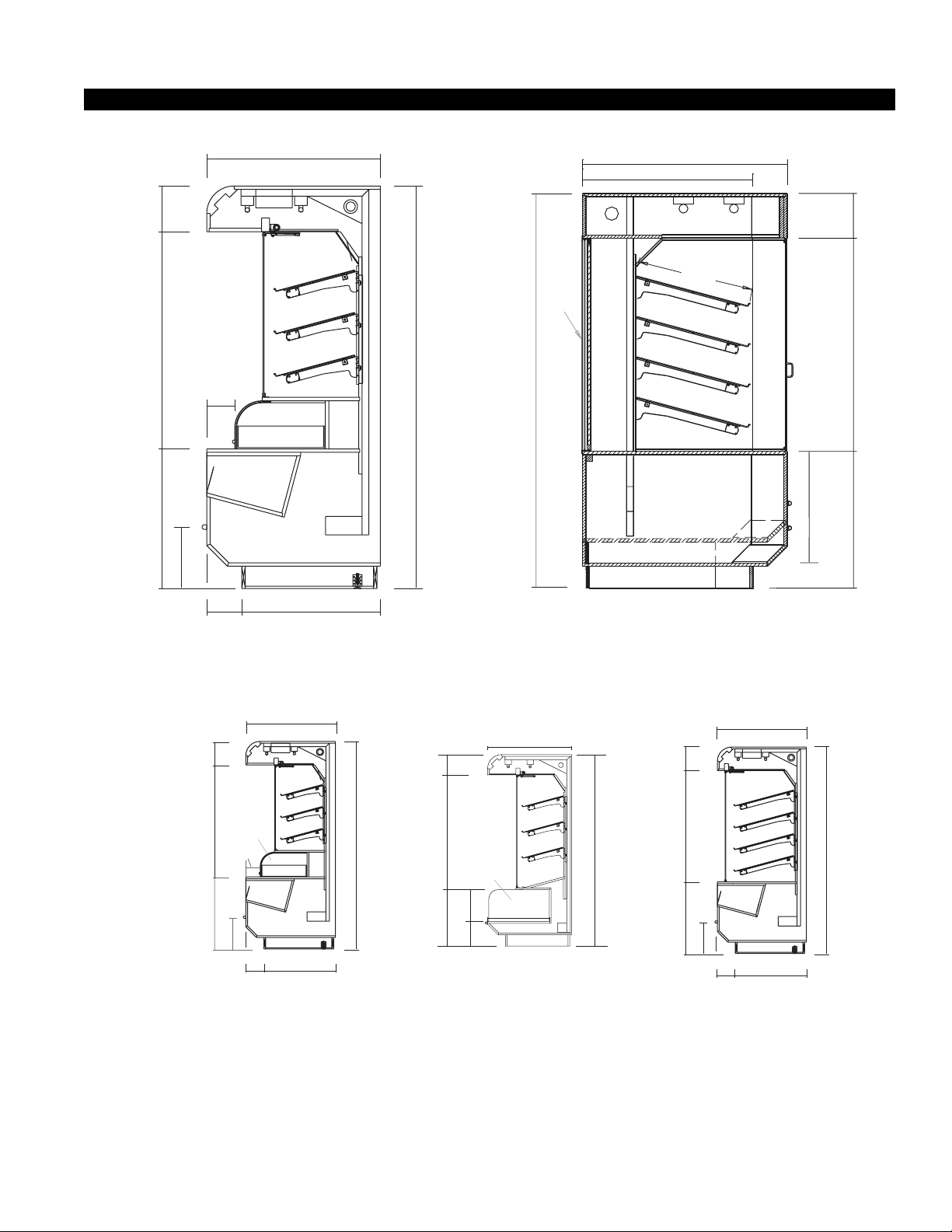
VTB
Vista Tower Merchandiser Bakery Case
Scale = 1/2"
8
7
1
/
2
"
(
M
a
t
c
h
e
s
S
e
l
f
C
o
n
t
a
i
n
e
d
H
e
i
g
h
t
)
4
5
3
/4"
3
8
"
4
7
1
/
2
"
3
0
"
(
M
a
t
c
h
e
s
S
e
l
f
C
o
n
t
a
i
n
e
d
H
e
i
g
h
t
)
2
4
1
/
2
"
(
M
a
t
c
h
e
s
S
e
l
f
C
o
n
t
a
i
n
e
d
H
e
i
g
h
t
)
1
0
"
1
10''
''
2
/
47
''
2
/
30
Rev. 0309
Cut & Plan Views
38''
'
'
8
1
88''
6 1/8''
Cookie Bin
1
7
''
''
8
/
3
13
30 3/8''7 5/8''
VSG
Optional Cookie Bin and 3 Shelves
1
10''
/2''30
47
/2''
1
3
Optional Cookie Bin and 3 Shelves
Cookie
Bin
6 1/8''
/8''
13
5
7
Scale = 1/2"
38''
1
7
'
'
/8''
30 3/8''
VSG
Scale = 1/4"
"
4
/
3
'
'
8
1
88''
8
"
2
/
1
48
Refrigerated
Lower Storage
25"
Optional
"
4
/
3
13
"
2
/
1
10
Bakery Tower with Optional
Refrigerated Lower Storage
36"
"
8
1
3
26
/4"
VSG-DSS
Scale = 1/4"
10''
'
'
6
2
/2''
"
4
/
1
82
1
47
88''
1
7
/8''
13
''
5
7
/8''
30 3/8''
/2''
1
30
3
VSG
Optional 4 Deep Shelf
Scale = 1/4"
3
38''
IGSV-VTB, VSG-0309
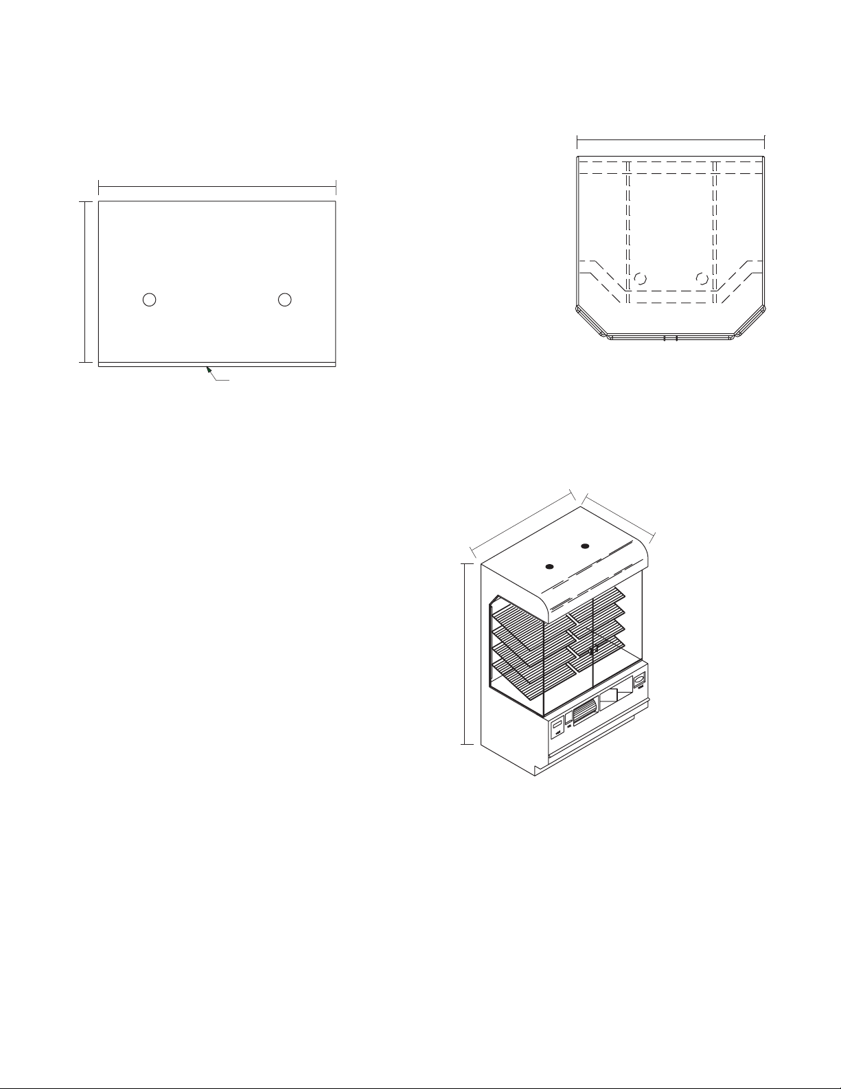
1” Bumper
38''
48" 2-Door Case
56" 2-Door Case • 78" 3-Door Case
56" (78")
VSG
Plan
Scale = 1/2"
88''
56''
8
VTB
Scale = 1/4"
''
Bakery Vista Tower Merchandiser
3
VSG
Overhead view
Scale = 1/4"
4
Installation
LOCATION
The refrigerated merchandisers have been designed for
use only in air conditioned stores where temperature
and humidity are maintained at or below 75°F and 55%
relative humidity. DO NOT allow air conditioning,
electric fans, ovens, open doors or windows (etc.) to
create air currents around the merchandiser, as this will
impair its correct operation.
Product temperature should always be maintained at a
constant and proper temperature. This means that from
the time the product is receiv ed, through storage,
preparation and display, the temperature of the product
must be controlled to maximize life of the product.
UNCRATING THE STAND
Place the fixture as close to its permanent position as
possible. Remove the top of the crate. Detach the walls
from each other and remove from the skid. Unbolt the
case from the skid. The fixture can now be lifted off the
crate skid. Lift only at base of stand!
EXTERIOR LOADING
These models have not been structurally designed to
support excessive external loading. Do not walk on
their tops; This could cause serious personal injury and
damage to the fixture.
DANGER!
SETTING AND JOINING
The sectional construction of these models enable them
to be joined in line to give the effect of one continuous
display. A joint trim kit is supplied with each joint.
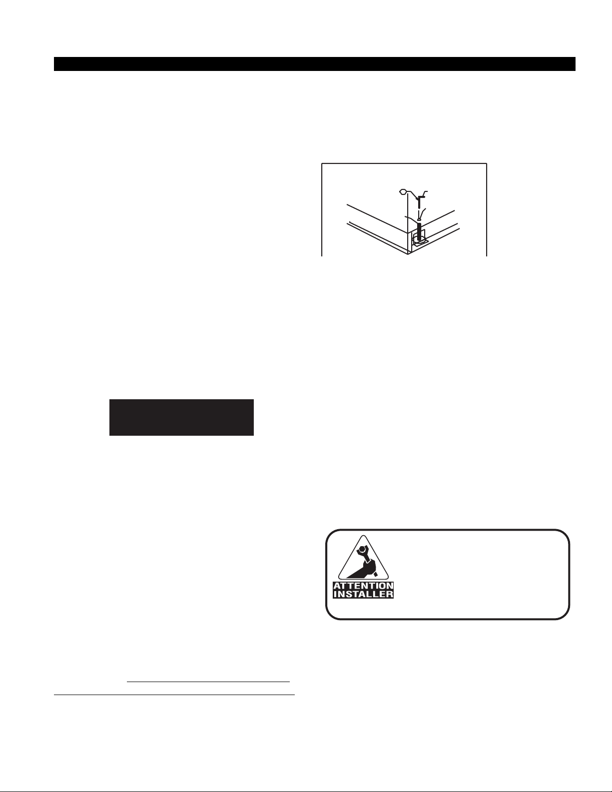
LEVELING
IMPORTANT! It is imperative that cases be leveled
from front to back and side to side prior to joining. A
level case is necessary to insure proper operation,
water drainage, glass alignment, and operation of the
hinges supporting the glass. Leveling the case correctly will solve most hinge operation problems.
NOTE: A. To avoid removing concrete flooring, begin lineup
leveling from the highest point of the store floor.
B.When wedges are involved in a lineup, set them first.
All cases were leveled and joined prior to shipment to
insure the closest possible fit when cases are joined in
the field. When joining, use a carpenter’s level and shim
legs accordingly. Case must be raised correctly, under
legs where support is best, to prevent damage to case.
Merchandisers must be installed level to ensure proper
operation of self closing doors. Place prybar under base
Rev. 0309
and lift. DO NOT LIFT END PANEL. Turn leveler,
with 5mm allen wrench, clockwise to raise, counter
clockwise to lower. Repeat process with other levelers
until case is level.
NOTE: To avoid removing concrete flooring, begin
lineup leveling from the highest point of the store.
1. Check level of floor where cases ar e to be set.
Determine the highest point of the floor; cases will
be set off this point.
2. Set first case, and adjust legs over the highest part
of the floor so that case is level. Prev ent damage –
case must be raised under leg or by use of 2x6 or
2x4 leg brace. Remove side and back leg braces
after case is set.
3. Set second case as close as possible to the first case,
and level case to the first using the instructions in
step one.
4. Apply masking tape 1/8" in from end of case on
inside and outside rear wall on both cases to be
joined.
5. Apply liberal bead of case joint sealant (butyl) to
rear adjoining wall of first case.
DO NOT USE PERMA GUM!
It is the contractor's
responsibility to install
case(s) according to local
construction and health
codes.
6. Slide second case up to first case snugly . Then lev el
second case to the first case so deck, bumper and
top are flush.
7. To compress silicone at joint, use two J urgenson
wood clamps. Mak e sure case is lev el from front to
back and side to side on inside bulkheads at joint.
8. Attach sections together via a 3 bolts located in the
5
IGSV-VTB, VSG-0309
base of the case. Secure the ov erhead structure by
bolting the rear mullions tegether.
Do not use bolts
9. Apply bead of silicone aling rear wall.
10. Use finger to smooth silicone as thin as possible at
masking tape
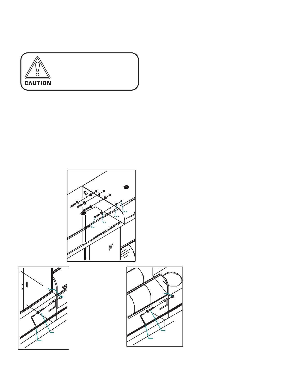
HEADER
Remove light diffuser of adjoining cases and attach
nut, bolt and washers as shown.
to pull cases together!
1.
INSTALLING PEDESTAL BASE CLOSE OFF
1. Bolt (1/4-16 x 1) front angle to base gusset. Do not
tighten.
2. Align front angle to floor .
3. Tighten front angle to base gusset.
4. Align the threaded rod in the fr ont close-off with
the 1/4" hole located in front angle, then bolt
together.
5. Slide rear close-off around case r ear frame and slide
between front angle and fr ont close-off. After a
secure fit bolt on rear close-off to r ear gusset.
2. BASE (case access two
sides) Bolt cases together
as shown.
3. BASE ((case access
one side) Bolt cases
together as shown.
6
 Loading...