

Page 1
Low Temperature Self Contained
®
WARNINGS:
If the information in these instructions are not followed
exactly, a fire or explosion may result, causing property
damage, personal injury or death.
Installation and service must be performed by a qualified
installer or service agency.
READ THE ENTIRE MANUAL BEFORE
INSTALLING OR USING THIS EQUIPMENT.
The unit uses R-290 gas as the refrigerant. R-290 is
flammable and heavier than air. It collects first in low
areas but can be circulated by the fans. If propane gas
is present or even suspected, do not allow untrained
personnel to attempt to find the cause. The propane
gas used in the unit has no odor. The lack of smell does
not indicate a lack of escaped gas. If a leak is detected,
immediately evacuate all persons from the store, and
contact the local fire department to advise them that
a propane leak has occurred. Do not let any persons
back into the store until the qualified service technician
has arrived and that technician advises that it is safe to
return to the store. No open flames, cigarettes or other
possible sources of ignition should be used inside or in
the vicinity of the units.
VRL (120V)
Glass Door Merchandisers
with R-290 Refrigerant
Installation &
Operation Manual
FAILURE TO ABIDE BY THIS WARNING COULD
RESULT IN AN EXPLOSION, DEATH, INJURY AND
PROPERTY DAMAGE.
IMPORTANT
Keep in store for future reference!
MANUAL - SELF CONTAINED R290 VRL 120V I/O
P/N 3155541_D
July 2023
Spanish 3155542
Page 2
2 InstallatIon
BEFORE YOU BEGIN
Read these instructions completely and carefully.
PERSONAL PROTECTION EQUIPMENT (PPE)
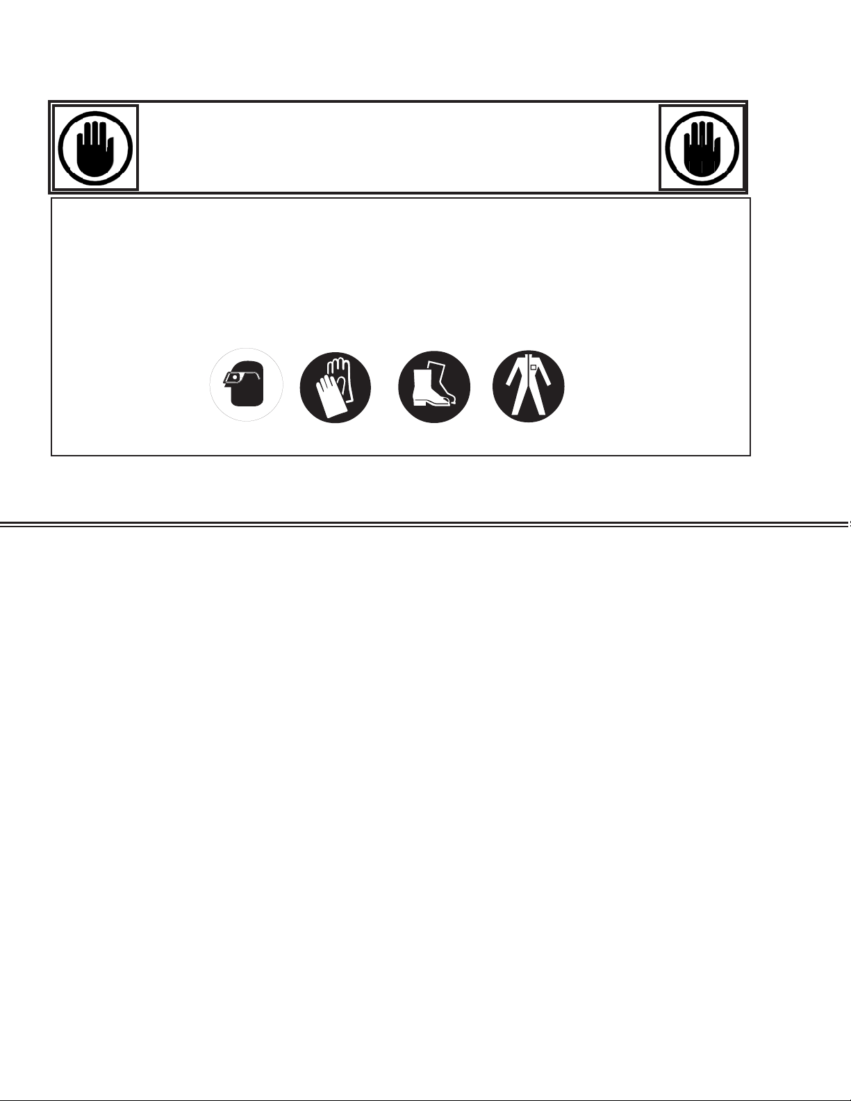
Personal Protection Equipment (PPE) is required whenever installing or servicing this
equipment. Always wear safety glasses, gloves, protective boots or shoes, long pants, and a
long-sleeve shirt.
1. If the information in these instructions is not followed exactly, a fire or explosion may result, causing property damage, personal
injury or death.
2. Installation and service must be performed by a qualified installer or service agency.
3. This unit is designed only for use with R-290 gas as the designated refrigerant.
THE REFRIGERANT LOOP IS SEALED. ONLY A QUALIFIED TECHNICIAN SHOULD ATTEMPT TO SERVICE!
• Propane is flammable and heavier than air.
• It collects first in the low areas but can be circulated by the fans.
• If R-290 (propane) is present or even suspected, do not allow untrained personnel to attempt to find the cause.
• The propane gas used in the unit has no odor.
• The lack of smell does not indicate a lack of escaped gas.
• If a leak is detected, immediately evacuate all persons from the store, and contact the local fire department to advise them that a
pro pane leak has occurred.
• Do not let any persons back into the store until the qualified service technician has arrived and that technician advises that it is
safe to return to the store.
• A hand-held propane leak detector (“sniffer”) shall be used before any repair and/or maintenance.
• No open flames, cigarettes or other possible sources of ignition should be used inside the building where the units are located
until the qualified service technician and/or local fire department determines that all propane has been cleared from the area and
from the refrigeration systems.
• Component parts are designed for propane and non-incendive and non-sparking. Component parts shall only be replaced with
identical repair parts.
FAILURE TO ABIDE BY THIS WARNING COULD RESULT IN AN EXPLOSION, DEATH, INJURY AND PROPERTY DAMAGE.
PN_3155541_D U.S. & Canada 1-800-922-1919 • Mexico 1-800-890-2900 • www.hussmann.com
U.S. & Canada 1-800-922-1919 • Mexico 1-800-890-2900 • www.hussmann.com
Page 3
PN_3155541_D 3
AT TENTION
Merchandiser must operate for 24 hours
Merchandiser must operate for 24 hours
before loading product!
before loading product!
Regularly check merchandiser temperatures.
Regularly check merchandiser temperatures.
Do not break the cold chain. Keep products
Do not break the cold chain. Keep products in
in freezer before loading into merchandiser.
freezer before loading into merchandiser.
These merchandisers are designed
These merchandisers are designed
for only pre-frozen products.
for only pre-frozen products.
IMPORTANT
KEEP IN STORE FOR FUTURE REFERENCE
Quality that sets industry standards!
12999 St. Charles Rock Road • Bridgeton, MO 63044-2483
U.S. & Canada 1-800-922-1919 • Mexico 1-800-890-2900
www.hussmann.com
© 2023 Hussmann Corporation
HUSSMANN CORPORATION • BRIDGETON, MO 63044-2483 U.S.A.
VRL Merchandisers
Page 4
4 InstallatIon
REVISION HISTORY
REVISION D
Added solid shelf installation for VRL3; Added 3-door case; added service replacement info
for inverter, condenser motor, compressor, and solenoid valves
REVISION C
Added 3-door case; added service replacement info for inverter, condenser motor, compressor, and solenoid valves
REVISION B
Added the 2-door case
ORIGINAL ISSUE — NOVEMBER 2021
AT TENTION
Adjust closing torque by turning the bottom
hinge pin in the direction the door closes.
Use a 1/2 inch (13 mm) wrench, and turn
the hinge pin until the door closes on its own.
Usually it takes two clicks or a half turn.
August 31, 2018
This warning does not mean that Hussmann products
will cause cancer or reproductive harm, or is in
violation of any product-safety standards or
requirements. As clarified by the California State
government, Proposition 65 can be considered more of
a ‘right to know’ law than a pure product safety law.
When used as designed, Hussmann believes that our
products are not harmful. We provide the Proposition
65 warning to stay in compliance with California State
law. It is your responsibility to provide accurate
Proposition 65 warning labels to your customers when
necessary. For more information on Proposition 65,
please visit the California State government website.
* * * * * * * * * * * * * * * * * * * * * * * * * *
ANSI Z535.5 DEFINITIONS
• DANGER – Indicate[s] a hazardous
situation which, if not avoided, will
result in death or serious injury.
• WARNING – Indicate[s] a hazardous
situation which, if not avoided, could
result in death or serious injury.
• CAUTION – Indicate[s] a hazardous
situation which, if not avoided, could
result in minor or moderate injury.
• NOTICE – Not related to personal injury –
Indicates[s] situations, which if not avoided,
could result in damage to equipment.
Do NOT remove shipping crate until the
merchandiser is positioned
for installation.
Excessive ambient conditions may
cause condensation and therefore
sweating of doors. Facility operators
should monitor doors and oor
conditions to ensure safety of persons.
Case ventilation openings must be clear
of any obstructions. Do not damage the
refrigerant circuit.
PN_3155541_D U.S. & Canada 1-800-922-1919 • Mexico 1-800-890-2900 • www.hussmann.com
Page 5
PN_3155541_D 5
INSTALLATION
NSF LISTING
These merchandisers are manufactured to meet
ANSI / UL 471 standard requirements for
safety. Proper installation is required to maintain
this listing. Near the serial plate, each case
carries a label identifying the type of conditions
for which the merchandiser was tested.
ANSI/NSF-7 Type II – Display
Refrigerator / Freezer Intended for
80°F / 55% RH Ambient Application
ANSI/NSF-7 – Display Refrigerator
Intended for Bulk Produce
FEDERAL / STATE REGULATION
These merchandisers, at the time they are
manufactured, meet all federal and state /
provincial regulations.
Apparent Loss or Damage
If there is an obvious loss or damage, it must
be noted on the freight bill or express receipt
and signed by the carrier’s agent; otherwise,
carrier may refuse claim.
Concealed Loss or Damage
When loss or damage is not apparent until
after equipment is uncrated, retain all packing
materials and submit a written response to the
carrier for inspection within 15 days.
LOCATION
These merchandisers are designed for
displaying products in air conditioned stores
where temperature is maintained at or below
the ANSI / NSF-7 specified level and relative
humidity is maintained at or below 55%.
HUSSMANN PRODUCT CONTROL
The serial number and shipping date of all
equipment is recorded in Hussmann’s files
for warranty and replacement part purposes.
All correspondence pertaining to warranty or
parts ordering must include the serial number
of each piece of equipment involved. This is
to ensure the customer is provided with the
correct parts.
SHIPPING DAMAGE
All equipment should be thoroughly examined
for shipping damage before and during
unloading. This equipment has been carefully
inspected at our factory. Any claim for loss
or damage must be made to the carrier. The
carrier will provide any necessary inspection
reports and/or claim forms.
Recommended operating ambient
temperature is between
60°F (15.6°C) to 80°F (26.7°C).
Maximum relative humidity is 55%.
Placing refrigerated merchandisers in direct
sunlight, near hot tables or near other heat
sources could impair their efficiency. Like
other merchandisers, these merchandisers
are sensitive to air disturbances. Air currents
passing around merchandisers will seriously
impair their operation. Do NOT allow air
conditioning, electric fans, open doors or
windows, etc. to create air currents around the
merchandiser.
HUSSMANN CORPORATION • BRIDGETON, MO 63044-2483 U.S.A.
VRL Merchandisers
Page 6
6 InstallatIon
SELF CONTAINED (LOCATION)
Product should always be maintained at proper temperature. This means that from the time the
product is received, through storage, preparation and display, the temperature of the product
must be controlled to maximize the life of the product.
Be sure to position self contained merchandisers properly.
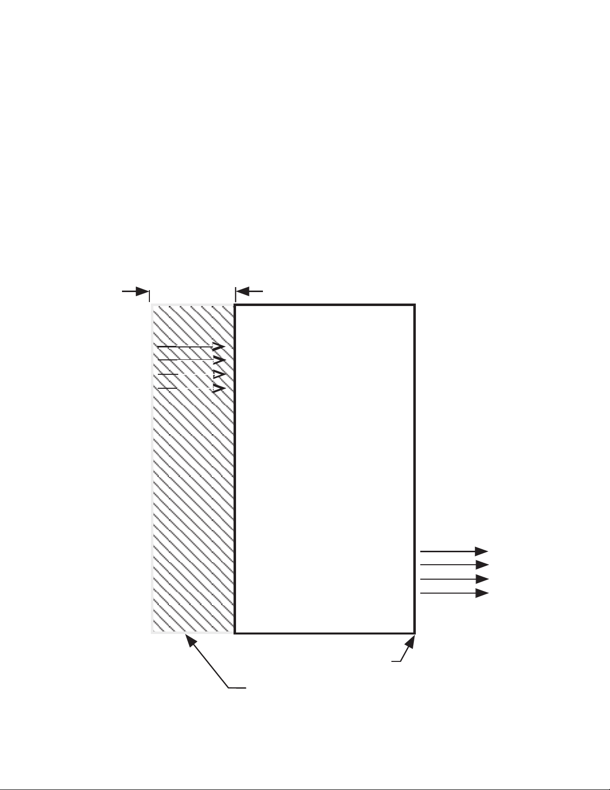
VRL models have vented base panels to allow air circulation through the condensing unit.
Allow for a minimum 36 in. clearance in the front. Blocking or restricting air flow will adversely
affect performance and may damage the refrigeration system.
36 in.
36 in.
Air Intake
Air Intake
Front
Front
(Plan View)
(Plan View)
Zero Clearance
Zero clearance required on sides
1-inch clearance at TOP and REAR
at Sides and Rear
Rear
Rear
Air Exhaust
36 in. Clearance at
36 in. Clearance
Front
at Front
PN_3155541_D U.S. & Canada 1-800-922-1919 • Mexico 1-800-890-2900 • www.hussmann.com
Page 7
PN_3155541_D 7
UNLOADING
Unloading from Trailer:
Lever Bar (also known as a Mule, Johnson
Bar, J-Bar, Lever Dolly, or Pry Lever)
Move the merchandiser as close as possible
to its permanent location and remove
all packaging. Check for damage before
discarding packaging. Remove all separately
packed accessories such as kits and shelves.
Improper handling may cause damage to
the merchandiser when unloading. To avoid
damage:
1. Do not drag the merchandiser out of the
trailer. Use a Johnson bar (Mule).
2. Use a forklift or dolly to remove the
merchandiser from the trailer.
Do NOT stand or walk on top of
merchandiser. Do not store items or
ammable materials atop the unit.
EXTERIOR LOADING
Do NOT walk on top of the merchandiser or
damage to the merchandisers and serious
personal injury could occur.
merchandisers are not structurally
designed to support excessive external
loading such as the weight of a person.
Do not place heavy objects on the
merchandiser.
SHIPPING SKID
Each merchandiser is shipped on a skid to
protect the merchandiser’s base and to make
positioning the case easier.
Remove the top of the crate and detach walls
from each other (if applicable). Lift crate from
the skid. Unscrew the case from the skid. The
merchandiser can now be lifted off the crate
skid. Lift only at base of skid! Remove any
braces and/or skids attached (blanket wrapped
merchandiser may have skids).
DO NOT TILT MERCHANDISER ON ITS
SIDE OR END WHEN REMOVING SKID.
Do not use mechanical devices or other means
to accelerate the defrosting process.
Do not use electrical appliances inside the food
storage compartments of the case.
Case ventilation openings must be clear of any
obstructions. Do not damage the refrigerant
circuit.
HUSSMANN CORPORATION • BRIDGETON, MO 63044-2483 U.S.A.
Once the skid is removed, the merchandiser
must be lifted —NOT PUSHED— to
reposition. To remove the skid, remove screws
attaching skid to the merchandiser.
Check floor where merchandisers are to be set
to if it is a level area. Determine the highest
part of the floor.
VRL Merchandisers
Page 8
8 InstallatIon
MODEL DESCRIPTION
VRL merchandisers are low temperature selfcontained cabinets, designed for pre-packaged
frozen food or products that require frozen
temperatures for conservation.
Design Features:
- Contemporary styling places maximum
attention on merchandising
- All VRL merchandisers have the same access
panel design for commonality between
merchandisers
- Self-closing Innovator doors. Positive seal,
torsion type closure system
- Triple-pane thermal insulated glass door
assemblies
- Magnetic door gaskets of one-piece
construction, removable without tools for
ease of cleaning
- Merchandiser can be placed against wall no air gap is required behind the case
- Digital display in center of case air grille
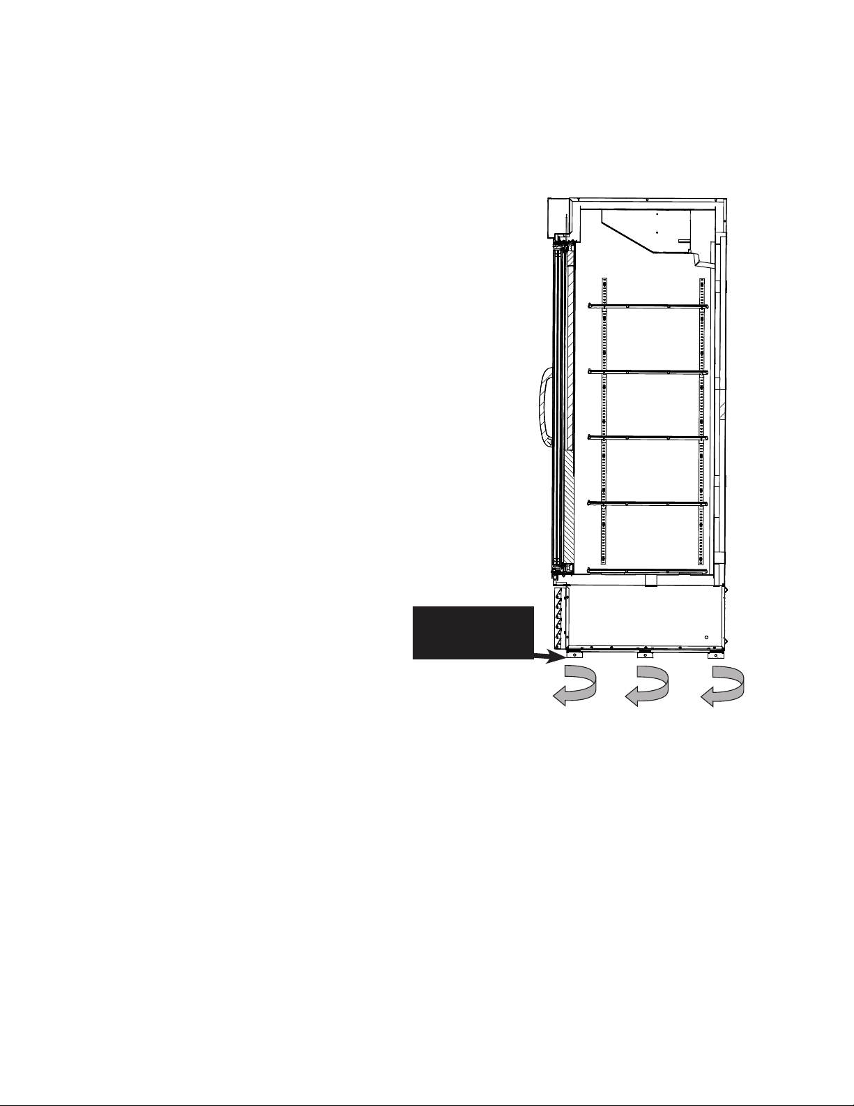
CABINET LEVELING
This merchandiser must be installed level
(from back to front, and side to side) to allow
maximum draining of the condensate water as
well as proper door alignment and operation.
Choose a level area to install case.
These cases have adjustable leg leveler at
center front and back. Turn the leg levelers
clockwise to add length to each leg for leveling.
Adjustable
Leg Levelers
PN_3155541_D U.S. & Canada 1-800-922-1919 • Mexico 1-800-890-2900 • www.hussmann.com
Page 9
PN_3155541_D 9
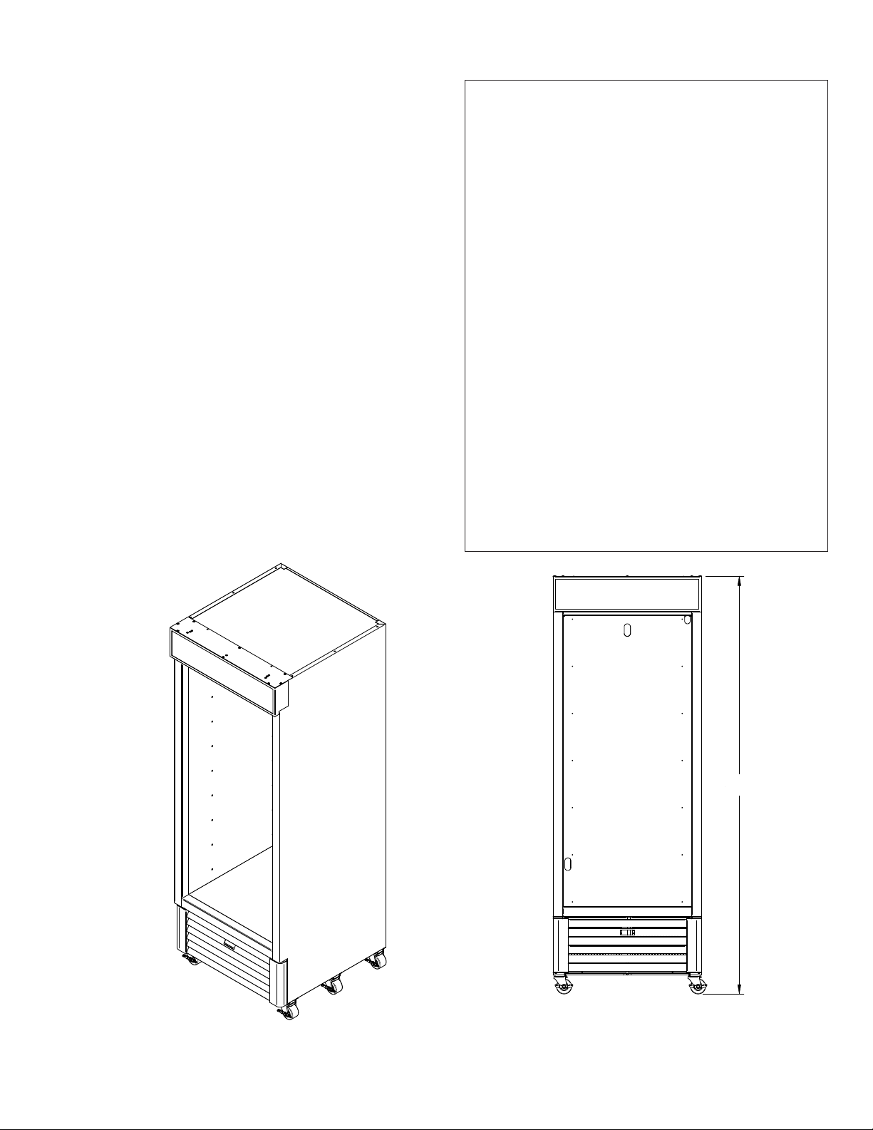
83.19
CASTERS
When optional casters are used, screw them
tight to the merchandiser base. Once in final
position, lock each caster. This option is a
ship loose kit. As a standard offering, this
merchandiser is fabricated with hockey puck
style leveler.
FIELD REQUIRED TOOLS
Pry (J) bar to lift up case to remove leg levelers.
Make sure the adjustable wrench used has a
minimum opening of 2
5
/16".
HUSSMANN CORPORATION • BRIDGETON, MO 63044-2483 U.S.A.
83.19"
(1-door model shown)
Case height is the same for
1, 2 and 3-door case models
VRL Merchandisers
83.19
Page 10
10 InstallatIon
SHELF AND WIRE PRODUCT STOP
INSTALLATION
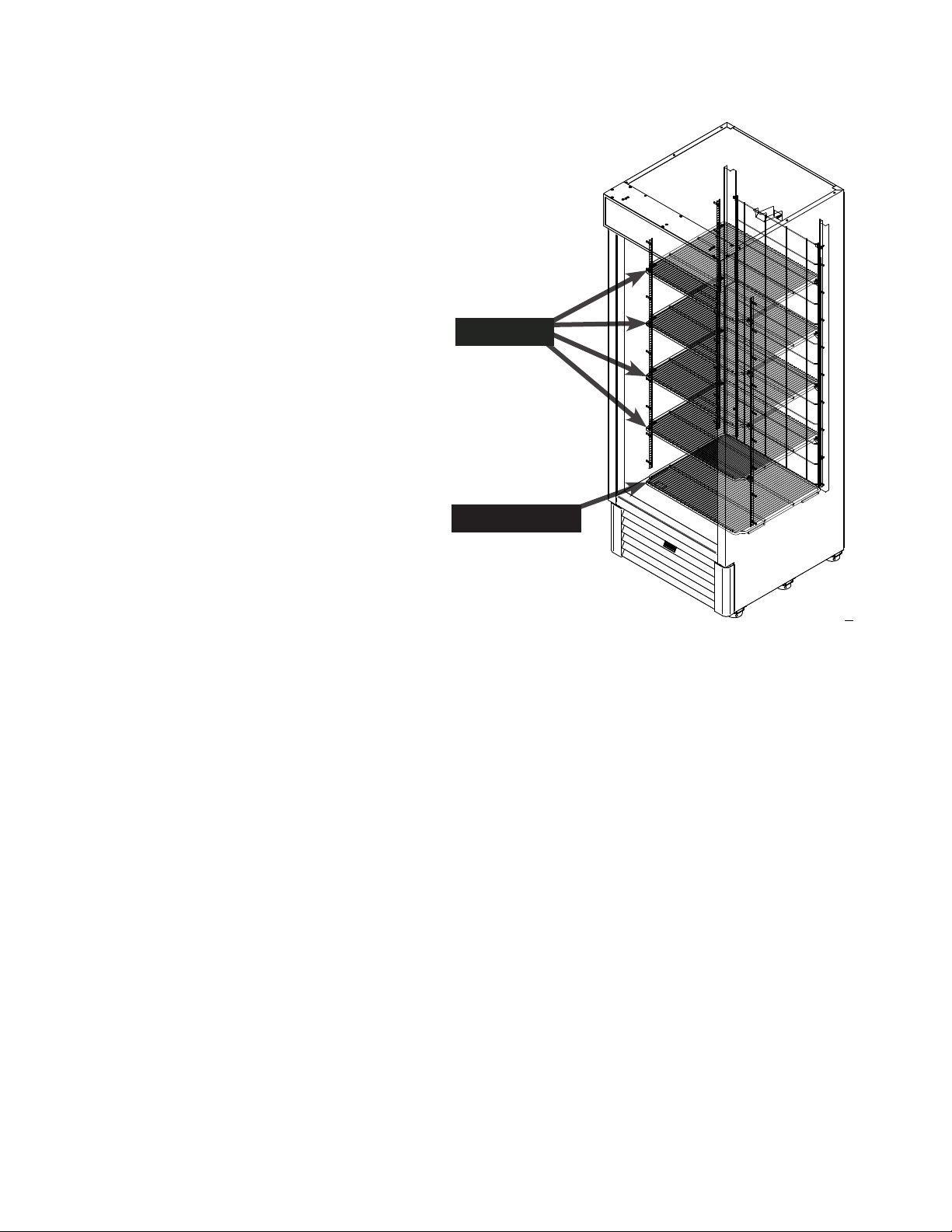
After the cabinet is leveled, the shelves may
be installed. Wire shelves are adjustable.
Shelf spacing can be adjusted by positioning
the shelf clips according to individual loading
requirements.
VRL merchandisers have four movable wire
shelves and one bottom wire shelf per door
as a standard option. Extra shelves can be
ordered as optional kits.
Shelves
Bottom Shelf
PN_3155541_D U.S. & Canada 1-800-922-1919 • Mexico 1-800-890-2900 • www.hussmann.com
Page 11
PN_3155541_D 11
SOLID SHELF INSTALLATION
Solid shelf shown in these instructions only applies
to VRL3B1A merchandiser models.
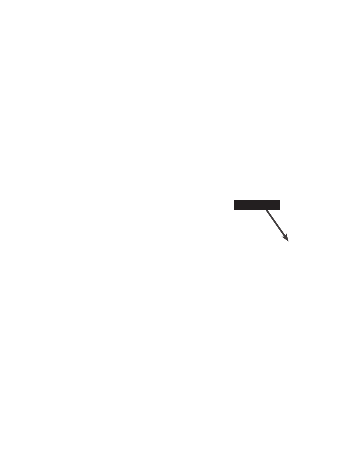
The illustration below shows the arrangement
of shelves shipped from the factory. Shelves
must be repositioned to ensure proper air
circulation and refrigeration performance.
Remove the plastic clips from the shelves after
placing the case in its final location. Shelf
repositioning is shown on the next page.
This model is specially designed for use with five
standard shelves and one bottom shelf as it was
shipped from the factory. Do not add additional
shelving. Use of unauthorized specialty shelving
or additional shelving will hamper refrigeration
performance.
Please consult your Hussmann representative
to ensure the optimum performance of all
Hussmann equipment.
Plastic Clip
HUSSMANN CORPORATION • BRIDGETON, MO 63044-2483 U.S.A.
VRL Merchandisers
Page 12
12 InstallatIon
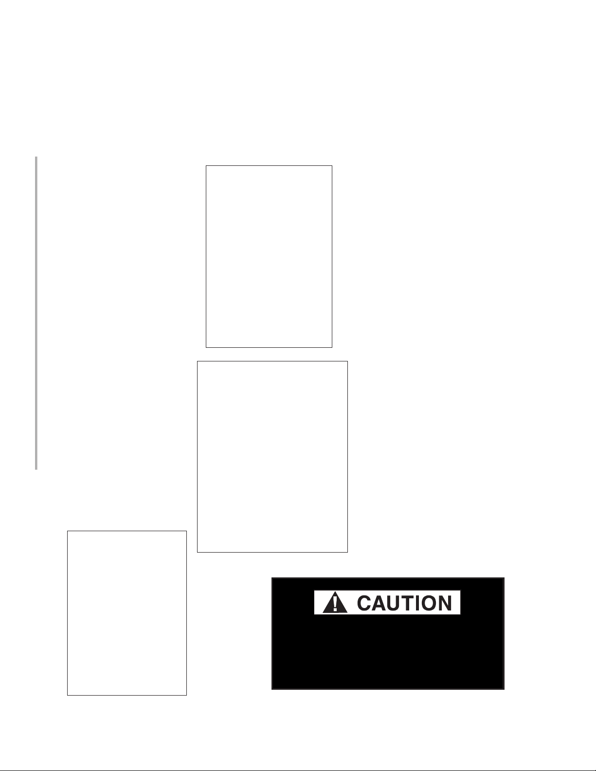
Begin installing shelves at the lowest row. Insert the shelf into the slots. Be sure to count the number of
slots between shelves as shown in the illustrations below. Tabs must be seated firmly into position.
• Leave two slots between the lower shelf and the standard shelf (Detail C).
• Leave four slots between the lower shelf and the shelf to be installed above it (Detail A).
• The top shelf should have six slots shown above it (Detail B).
Case cross-section view shows the
recommended distance between each
shelf, allowing the proper airow along
the cabinet.
Shelves are designed to support a maximum
load of 150 lbs. Exceeding this load can cause
damage to the shelves, case, damage to store
products, and potentially create a hazardous
condition for customers and store personnel.
PN_3155541_D U.S. & Canada 1-800-922-1919 • Mexico 1-800-890-2900 • www.hussmann.com
Page 13
PN_3155541_D 13
LAMPS
The light switch for the lamps is located at the
top of the fan plenum on the righthand side as
shown below. The switch controls the display
lighting and interior lighting.
Light Switch
Light Switch
11/29/2021
(1-door model shown) light switch location is in similar location
for all models - right hand side of the fan plenum
HUSSMANN CORPORATION • BRIDGETON, MO 63044-2483 U.S.A.
VRL Merchandisers
Page 14
14 InstallatIon
UNLESS OTHERWISE SPECIFIED
R
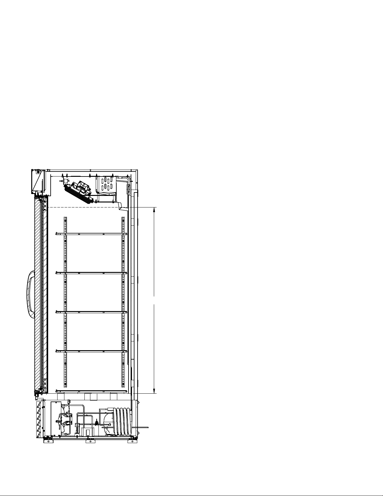
LOAD LIMIT LINE
STOCKING
Product should NOT be placed in case until merchandiser is at proper operating temperature.
The VRL merchandisers must remain in operation for at least 24 hours before product may be
loaded into case cabinet. Proper rotation of product during stocking is necessary to prevent
product loss. Always bring the oldest product to the front and set the newest to the back.
Air exhAust And return grille must remAin open And free of obstruction At All times.
Do not allow product, packages, signs, etc. to block air exhaust or return grille. Do not use
non-approved shelving, baskets, display racks, or any accessory that could hamper air curtain
performance.
LOAD LIMITS
Product must be within designated load limit
to ensure proper refrigeration and air curtain
performance.
do not violAte the loAd limit lines of vrl
cAses. product will block the cold Air
flow.
54.75
Load Limit for VRL
Merchandisers
SECTION A-A
PN_3155541_D U.S. & Canada 1-800-922-1919 • Mexico 1-800-890-2900 • www.hussmann.com
Page 15
PN_3155541_D 15
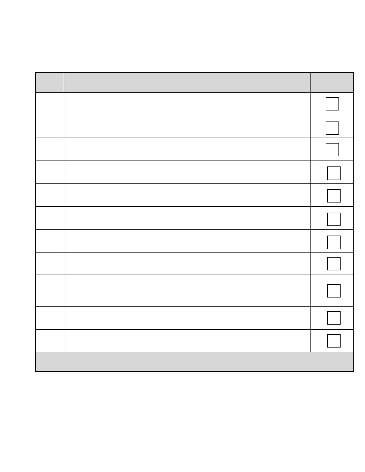
Hussmann Self-Contained Refrigeration Equipment Start Up Check List
***Please note that failure to follow this start-up document may void your factory warranty***
Step Startup Activity Check
1
Locate, read and maintain install/operation manual in a safe place for
future reference.
2 Examine unit. Conrm there is NO damage or concealed damage.
3 Level the unit, side to side and front to rear.
4 Remove all shipping brackets/compressor straps/bolts etc.
5
6
Unit must be run on a dedicated electrical circuit without the use of an
extension cord.
Ensure that the proper electrical requirements for the equipment are
supplied.
7 Verify eld electrical connections are tight.
8
Verify all electrical wiring is secured and clear of any sharp edges or
hot lines.
9
Verify the condensate drain line is properly trapped and pitched. Ensure
condensate drain tube is properly located against condensate pan.
10 Verify all required clearances on the sides and back of unit.
11
Verify there are no air disturbances external to the unit. Heat and air
registers, fans, and doors etc.
Advise owner/operator that merchandiser must operate at temperature for 24 hrs prior to
loading with product.
Form HSCW01 Rev. 30MAY12 P/N 0525209_B
LEGAL DISCLAIMER:
Hussmann shall not be liable for any repair or replacements made without the written consent of Hussmann, or when the product is installed or operated in
a manner contrary to the printed instructions covering installation and service which accompanied such product.
HUSSMANN CORPORATION • BRIDGETON, MO 63044-2483 U.S.A.
VRL Merchandisers
Page 16
16 ElEctrIcal / rEfrIgEratIon / controllEr
ELECTRICAL / REFRIGERATION / CONTROLLER
PLUG
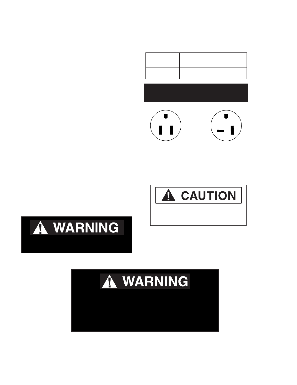
These merchandisers use a single, 9 ft. power
cord and plug.
1 and 2-door case models use a NEMA 5-15P
(plug). 3-door models use a NEMA 5-20P.
The plug is located on the right-hand side at the
rear of the merchandiser.
Disconnect power before servicing. VRL
merchandisers require a dedicated electrical
circuit with ground. 12AWG is the minimumsized acceptable wire.
• Always use a dedicated circuit with the
amperage stated on the unit.
• Plug into an outlet designed for the plug.
• Do not overload the circuit.
• Never use extension cords or adapters.
Nominal
Voltage
110-120 110 120
ALWAYS CHECK THE SERIAL PLATE FOR
COMPONENT AMPERES
NEMA 5-15P
115V 60Hz
(1 and 2-door
case models)
Minimum
Voltage
Maximum
Voltage
NEMA 5-20P
115V 60Hz
(3-door case
models)
• If in doubt, call an electrician.
Merchandiser must be grounded.
Do not remove the power supply cord ground.
To avoid serious injury or death from electrical shock, always
disconnect the electrical power at the main disconnect when
servicing or replacing any electrical component. This includes,
but is not limited to, such items as doors, lights, fans, heaters,
and thermostats.
Risk of Electric Shock. If cord or plug
becomes damaged, replace only with
a cord and plug of the same type.
— LOCK OUT / TAG OUT —
PN_3155541_D U.S. & Canada 1-800-922-1919 • Mexico 1-800-890-2900 • www.hussmann.com
Page 17
PN_3155541_D 17
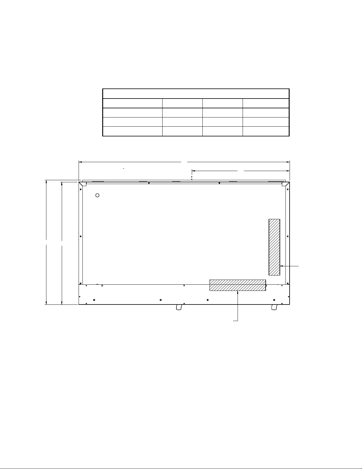
VRLB1A CASES GENERAL DIMENSIONS
ELECTRICAL BOX & POWER CORD LOCATION
VRLB1A CASES GENERAL DIMENSIONS
General dimensions 1 DOOR 2 DOOR 3 DOOR
Case Lenght (A) 29 5/8 (752) 54 (1372) 78 1/4 (1988)
Power cord outlet (B) 14 3/4 (375) 2 3/4 (70) 2 3/4 (70)
Electrical box (C) RIGHT RIGHT CENTER
A
B
31.75
31.26
ELECTRICAL BOX 2 & 3 DOORS
LOCATION MARKED IN TABLE
AS CENTER OR RIGHT
VRL1B1A ELECTRICAL BOX
POSITON
HUSSMANN CORPORATION • BRIDGETON, MO 63044-2483 U.S.A.
VRL Merchandisers
Page 18
18 ElEctrIcal / rEfrIgEratIon / controllEr
REVISION HISTORY
REV ECN DATE REVISION DESCRIPTION REV BY CHKD BY APPR BY
REFRIGERATION SYSTEM
FUNCTIONALITY
These cases can be used for frozen food. These
merchandiser model is self-contained and has
a controller that automates the refrigeration
cycle and the defrost cycle.
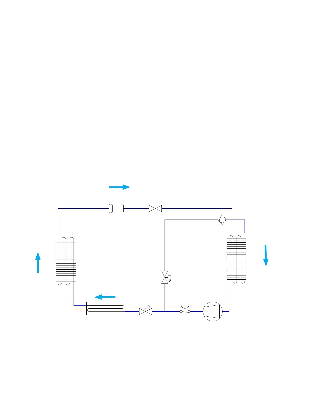
During refrigeration mode, the discharge line
solenoid valve (RSV) is energized and held
open, allowing the gas to flow through the
condenser.
Figure A. System Diagram- Refrigeration Mode
(This diagram is applicable for both 1 and 2-door models)
FILTER
DRIER
Once the refrigerant is in a liquid state, a
capillary tube is used as an expansion device
that feeds the evaporator.
During refrigeration mode, hot gas solenoid
valve (HGSV) is deenergized and closed.
CAP TUBE
CHECK
VALVE
CONDENSER
HGSV
CONDENSATE PAN
RSV
PRESSURE
SWITCH
COMPRESSOR
EVAPORATOR
PN_3155541_D U.S. & Canada 1-800-922-1919 • Mexico 1-800-890-2900 • www.hussmann.com
Page 19
PN_3155541_D 19
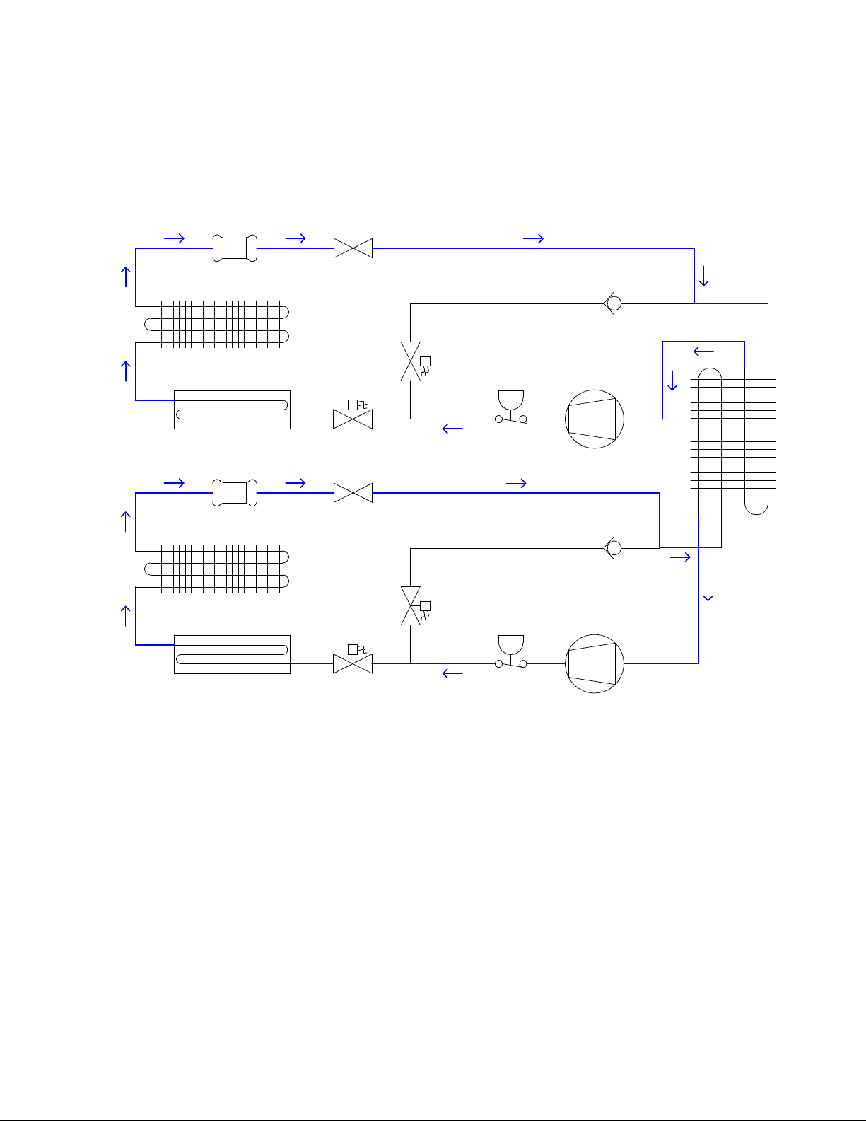
Figure B. System Diagram- Refrigeration Mode
(This diagram is applicable for 3-door models)
FILTER
DRIER
CONDENSER
CAP TUBE
CHECK
VALVE
HGSV
CONDENSATE PAN
FILTER DRIER
CONDENSER
CONDENSATE PAN
RSV
CAP TUBE
RSV
HGSV
PRESSURE
SWITCH
PRESSURE
SWITCH
COMPRESSOR
CHECK
VALVE
COMPRESSOR
EVAPORATOR
HUSSMANN CORPORATION • BRIDGETON, MO 63044-2483 U.S.A.
VRL Merchandisers
Page 20
20 ElEctrIcal / rEfrIgEratIon / controllEr
REFRIGERATION SYSTEM
FUNCTIONALITY
(Continued)
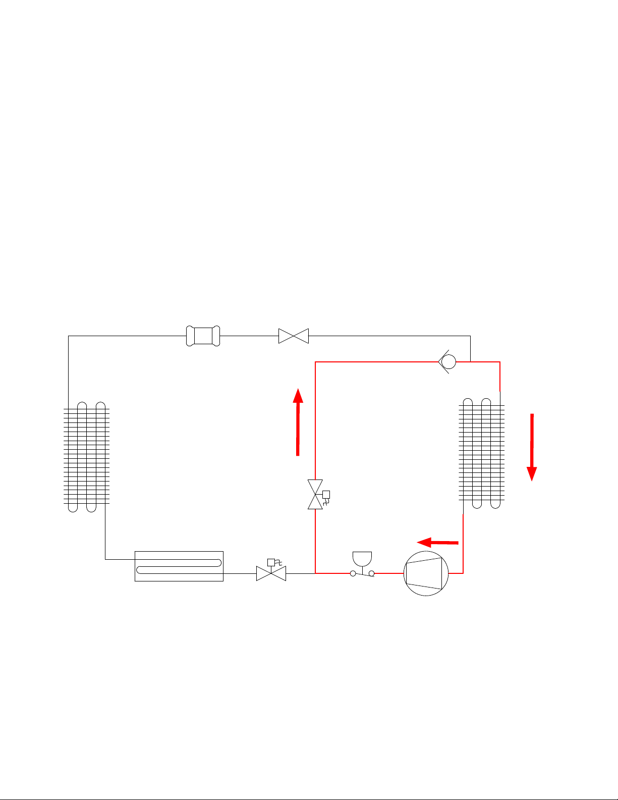
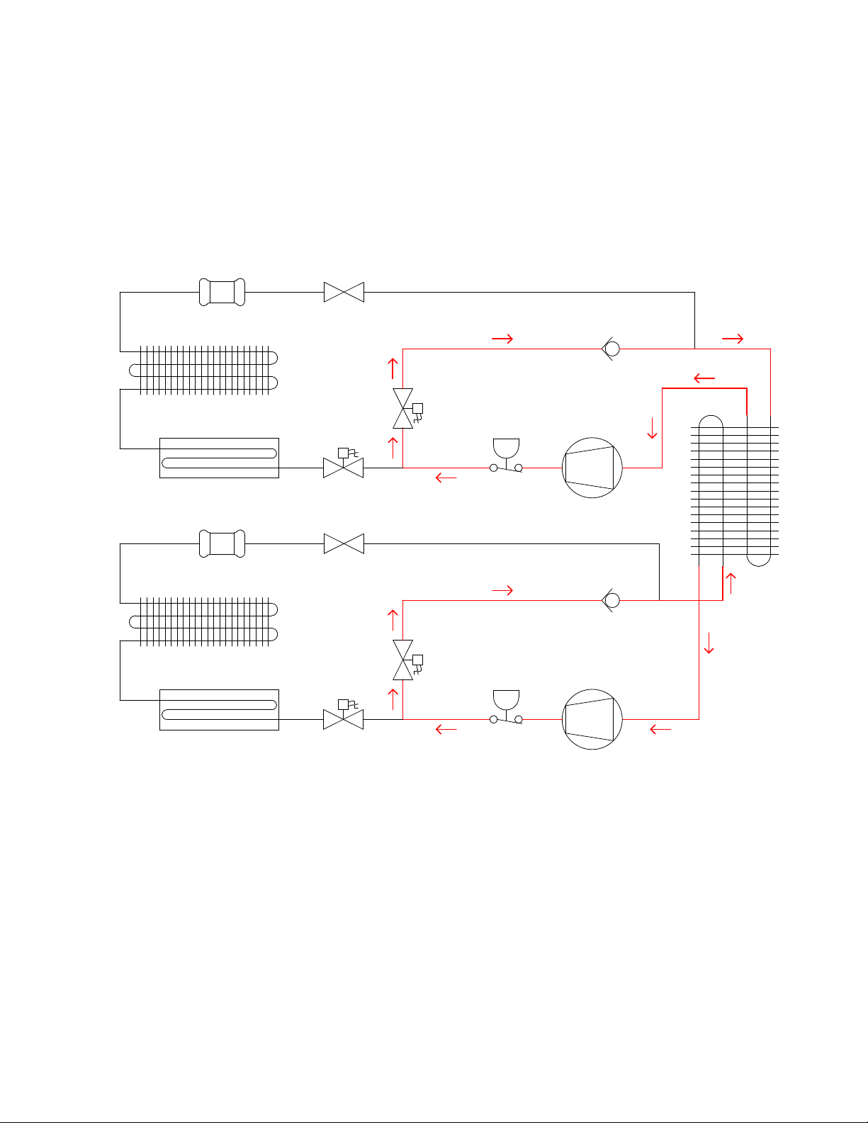
During defrost mode, the defrost solenoid
valve (HGSV) is energized and held open
allowing the gas to be redirected through the
evaporator inlet. The evaporator is split and
circuited for 2 refrigeration circuits.
Figure C. System Diagram - Defrost Mode - Hot Gas Bypass
(This diagram is applicable for both 1 and 2-door case models)
FILTER
DRIER
Defrost cycle is temperature-terminated with
a failsafe that is 50 minutes. Normally only 3
defrost per day are required.
CAP TUBE
CHECK
VALVE
CONDENSER
EVAPORATOR
HGSV
PRESSURE
CONDENSATE PAN
RSV
SWITCH
COMPRESSOR
PN_3155541_D U.S. & Canada 1-800-922-1919 • Mexico 1-800-890-2900 • www.hussmann.com
Page 21
PN_3155541_D 21
Figure D. System Diagram - Defrost Mode - Hot Gas Bypass
(This diagram is applicable for 3-door case models)
FILTER
DRIER
CONDENSER
CAP TUBE
CHECK
VALVE
HGSV
CONDENSATE PAN
FILTER DRIER
CONDENSER
CONDENSATE PAN
RSV
CAP TUBE
RSV
HGSV
PRESSURE
SWITCH
PRESSURE
SWITCH
COMPRESSOR
CHECK
VALVE
COMPRESSOR
EVAPORATOR
HUSSMANN CORPORATION • BRIDGETON, MO 63044-2483 U.S.A.
VRL Merchandisers
Page 22
22 ElEctrIcal / rEfrIgEratIon / controllEr
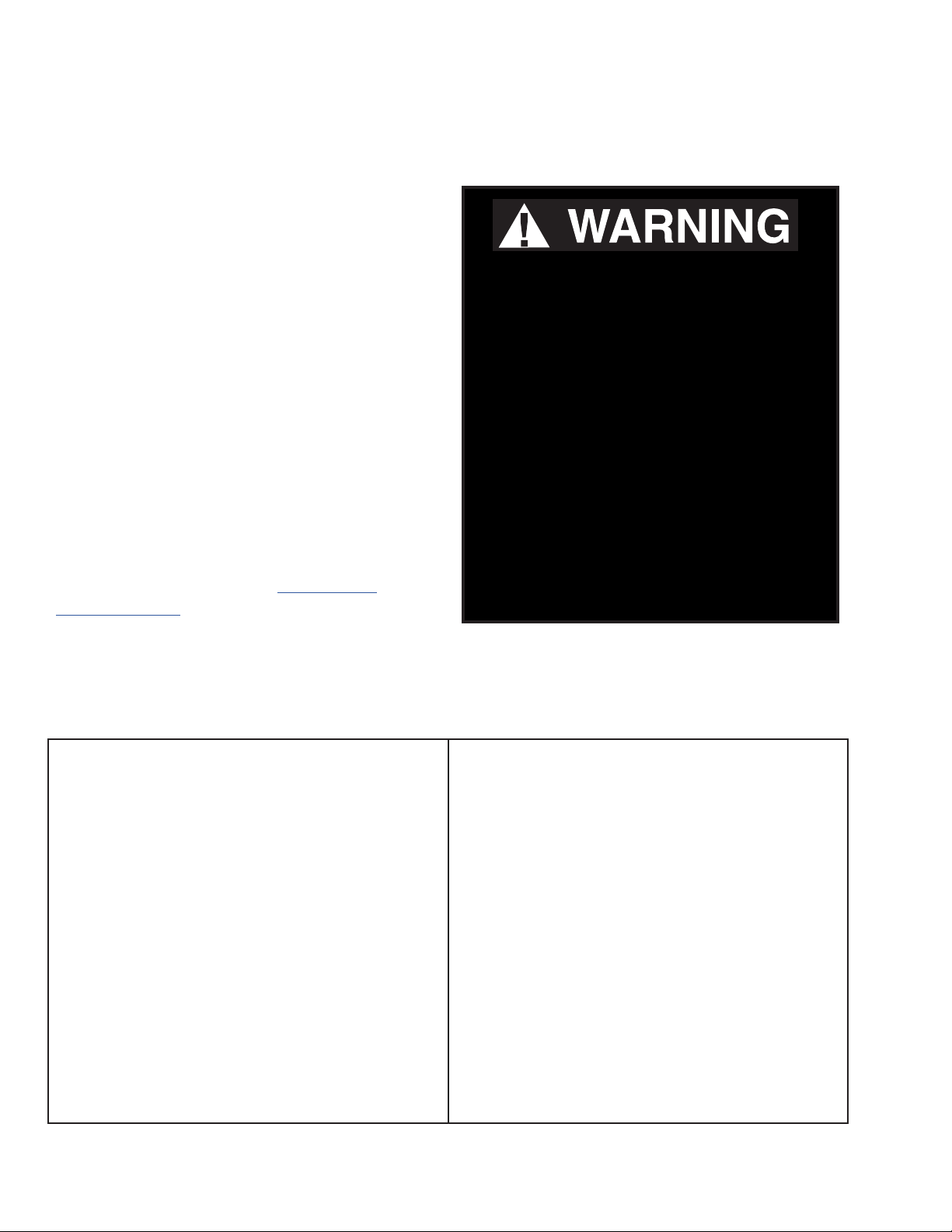
Before Beginning Any Service or Repair:
Use a hand-held propane leak detector (“sniffer”)
to ensure no propane is present in the immediate
area, the inside of the display case and the inside
of the refrigeration system. R-290 is an odorless
refrigerant. Keep the area clear of all customers
and non-essential or unauthorized personnel.
Only Hussmann or factory
trained technicians should
Verify that all repair parts are identical models
to the ones they are replacing. Do not substitute
parts such as motors, switches, relays, heaters,
compressors, power supplies or solenoids.
Failure to do so can result in an explosion,
death, injury and property damage. Parts
used on hydrocarbon cases must meet specic
UL certication for non-incendive or nonsparking components. Use only Hussmann
approved parts approved through the Hussmann
Performance Parts Website. https://parts.
hussmann.com/
Brazing must not begin before all propane has
been cleared from the immediate area — the
inside of the displays case and the inside of the
refrigeration system.
If a leak is detected, follow store safety
procedures. It is the store’s responsibility to have
a written safety procedure in place. The safety
procedure must comply with all applicable codes
such as local re department’s codes.
At minimum, the following actions are required:
• Immediately evacuate all persons from the
store, and contact the local re department to
advise them that a propane leak has occurred.
• Call Hussmann and/or a qualied service
agent and inform them that a propane sensor has
detected the presence of propane.
• Do not let any persons back into the store
until the qualied service technician has arrived
and that technician advises that it is safe to
return to the store.
service or repair this R-290
(propane) equipment.
Failure to follow
instructions can result in
an explosion, death, injury
and property damage.
• The propane gas used in the unit has no odor.
The lack of smell does not indicate a lack of
escaped gas.
• A hand-held propane leak detector
(“sniffer”) should be used before any repair and/
or maintenance is attempted. All repair parts
must be identical models to the ones they are
replacing.
• No open flames, cigarettes or other possible
sources of ignition should be used inside the
building where the units are located until the
qualied service technician and/or local re
department determines that all propane has been
cleared from the area and from the refrigeration
systems.
PN_3155541_D U.S. & Canada 1-800-922-1919 • Mexico 1-800-890-2900 • www.hussmann.com
Page 23
PN_3155541_D 23
REPLACING REFRIGERATION SYSTEM
COMPONENTS
Only Hussmann service technicians or
technicians qualied to handle R-290
(propane) refrigerant should service or
repair this R-290 (propane) equipment
Failure to follow instructions can result
in an explosion, death, injury and
property damage.
STEPS TO RECOVER REFRIGERANT
1. Make sure you are in a well ventilated area before
making any service or repair to the refrigeration
system.
2. Disconnect all power sources from the system.
Some systems may have more than one plug or
power supply.
3. Tap system with line tap valves, attaching gauges to
the high and low sides of the system.
refrigeration
line tapping
valve
This refrigeration system uses hot
gas defrost and incorporates a Normal
Closed Solenoid. In order to remove
all the refrigerant for service, the valve
must be held open while the refrigerant
is being evacuated. Failure to remove
all the refrigerant can cause a re or
explosion.
4. Connect hose to an evacuated recovery tank.
Open refrigeration gauges and recovery tank.
5. With the suction valve in vacuum, the refrigerant will
be recovered into the recovery tank.
6. Once recovered, close the tank valve and remove
the guage from the tank and connect nitrogen tank
to the system to purge it with nitrogen.
HUSSMANN CORPORATION • BRIDGETON, MO 63044-2483 U.S.A.
7. Pull vacuum to a minimum of 200 microns or
lower.
VRL Merchandisers
Page 24
24 ElEctrIcal / rEfrIgEratIon / controllEr
CHARGING
A calibrated scale with +/-2 gram accuracy
must be used to charge the system. The charge
amount is shown on the serial plate. Only R-290
grade refrigerant can be used. Standard propane
does not meet the purity/moisture content of
R-290, and therefore cannot be used to charge
cases.
Component parts shall be replaced with like
components, and servicing shall be done by
factory authorized service personnel only, so
No gas charge adjustments are allowed. When
connecting hoses between the refrigeration
as to minimize the risk of possible ignition
due to incorrect parts or improper service.
system, manifold gauges, and refrigerant
cylinder, ensure that the connections are secure
and there are no potential sources of ignition
nearby. Ensure that contamination of different
refrigerants does not occur when using charging
equipment.
Extreme care must be taken not to overll the
refrigeration system. After charging, carefully
disconnect the hoses, attempting to minimize
the quantity of refrigerant released. Further
leak check the service ports, hoses, refrigerant
tanks. The service ports shall be checked for
Use dedicated hoses to service R-290 (propane)
refrigeration systems. Hoses or lines should be
as short as possible to minimize the amount of
leaks using a hydrocarbon leak detector with a
sensitivity of 3 grams/year (0.106 Oz/year) leak
rate.
refrigerant contained in them.
Thoroughly leak check the service ports. If no
Ensure that the refrigeration system is properly
grounded prior to charging the system with
refrigerant, to avoid the potential for static
build-up.
leak is present, use a pinch-off tool to close
the ends of the service tubes before brazing
them shut. If a Schrader valve is used on the
compressor service tube, it must be removed and
the previous steps followed in order to braze the
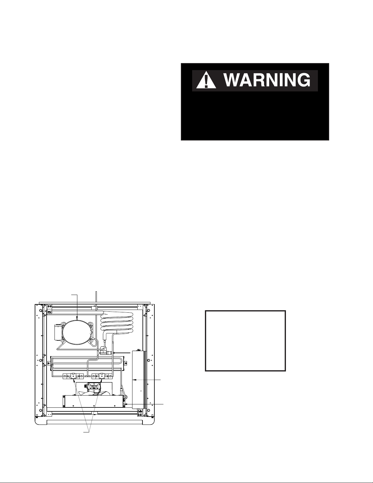
COMPRESSOR
service tube shut.
ELECTRICAL BOX
MICROCHANNEL
CONDENSER
SOLENOID VALVES
(1-door case shown)
PN_3155541_D U.S. & Canada 1-800-922-1919 • Mexico 1-800-890-2900 • www.hussmann.com
Page 25
PN_3155541_D 25
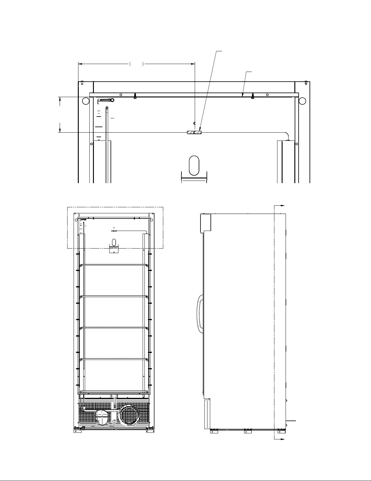
SECTION A-A
DETAIL B
4.50
ROOF TO
SENSOR
14.87
AIR DISCHARGE SENSOR
CENTERED BETWEEN SIDES
OF THE CASE
B
DETAIL B
4.50
ROOF TO
SENSOR
14.87
AIR DISCHARGE SENSOR
CENTERED BETWEEN SIDES
OF THE CASE
INTERIOR TOP PANEL
DISCHARGE SENSOR LOCATION
ROOF TO
VRL1B1A
14.87
4.50
SENSOR
AIR DISCHARGE SENSOR
CENTERED BETWEEN SIDES
OF THE CASE
INTERIOR TOP PANEL
DETAIL B
VRL1B1A
A
B
SECTION A-A
HUSSMANN CORPORATION • BRIDGETON, MO 63044-2483 U.S.A.
A
VRL Merchandisers
Page 26

26 ElEctrIcal / rEfrIgEratIon / controllEr
DISCHARGE SENSOR LOCATION
VRL2B1A
INTERIOR TOP PANEL
AIR DISCHARGE SENSOR
25.69
23.75 FROM
INTERIOR RIGHT
PANEL
4.50 ROOF TO SENSOR
PN_3155541_D U.S. & Canada 1-800-922-1919 • Mexico 1-800-890-2900 • www.hussmann.com
Page 27
PN_3155541_D 27
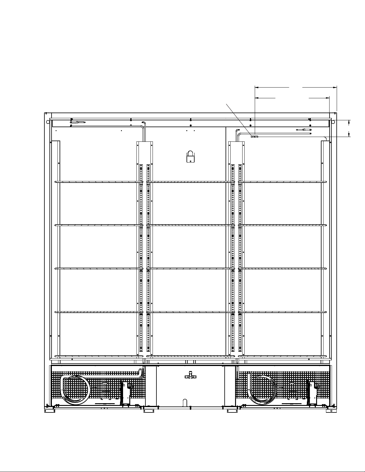
21.94
DISCHARGE SENSOR LOCATION
VRL3B1A
Air Discharge Sensor
20.00
FROM INTERIOR
RIGHT PANEL
4.50
HUSSMANN CORPORATION • BRIDGETON, MO 63044-2483 U.S.A.
VRL Merchandisers
Page 28
28 ElEctrIcal / rEfrIgEratIon / controllEr
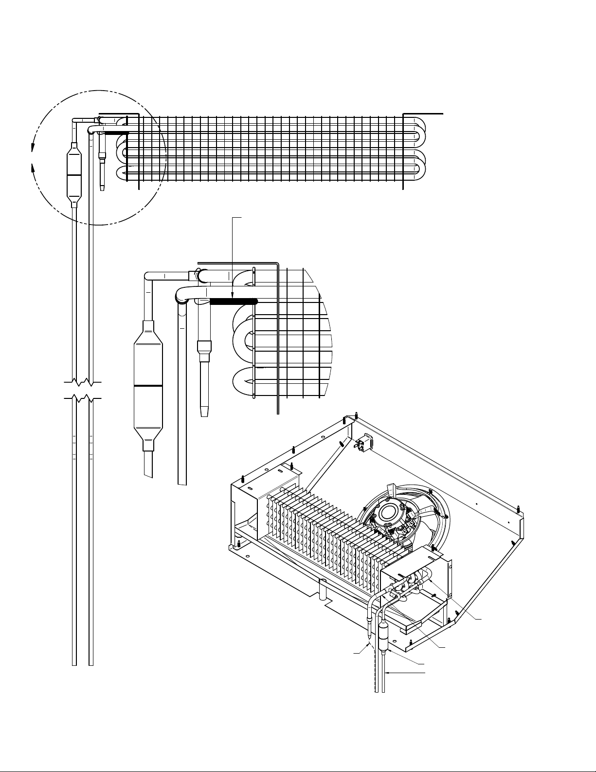
DEFROST SENSOR LOCATION
C
DEFROST SENSOR IS LOCATED
BELOW EVAPORATOR OUTLET TUBE
(APPLIES FOR VRL1B1A, VRL2B1A, VRL3B1A)
DETAIL C
EVAP OUTLET
CAPILLARY TUBE
PN_3155541_D U.S. & Canada 1-800-922-1919 • Mexico 1-800-890-2900 • www.hussmann.com
EVAP INLET
CHECK VALVE
HOT GAS LINE
Page 29
PN_3155541_D 29
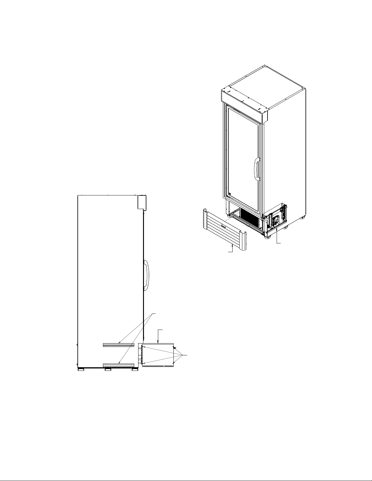
RIGHT VIEW
SUPPORT ELECTRICAL
BOX FIXED ON RIGHT
SIDE OF THE CASE
SLIDE ELECTRICAL BOX TO
FRONT OF THE CASE
UNSCREW COVER TO
ACCESS COMPONENTS
CONTROL BOX VRL1B1A
The control box is located in the machine
compartment. The control box contains
electrical components such as the controller
board, relays, etc. See data sheet for additional
details on the wiring diagram.
RIGHT VIEW
REMOVE ACCESS
PANEL, LIFT AND
PULL OFF
SUPPORT ELECTRICAL
BOX FIXED ON RIGHT
SIDE OF THE CASE
SLIDE ELECTRICAL BOX TO
FRONT OF THE CASE
UNSCREW COVER TO
ACCESS COMPONENTS
ELECTRICAL BOX
LOCATED ON THE RIGHT
SIDE OF THE CASE
HUSSMANN CORPORATION • BRIDGETON, MO 63044-2483 U.S.A.
VRL Merchandisers
Page 30
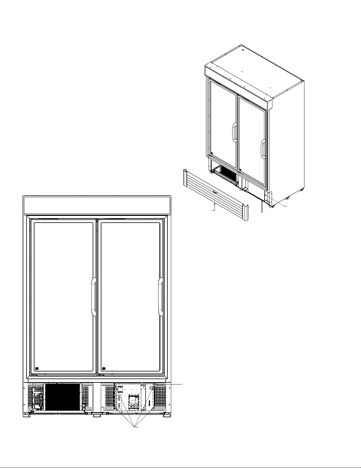
30 ElEctrIcal / rEfrIgEratIon / controllEr
UNSCREW COVER TO
ACCESS COMPONENTS
LOCATION ON THE FRONT
OF THE CASE PROVIDES
ACCESIBILITY TO ELECTRICAL
COMPONENTS WITHOUT THE
NEED TO UNSCREW THE BOX
CONTROL BOX VRL2B1A
The control box is located in the machine
compartment. The control box contains
electrical components such as the controller
board, relays, etc. See data sheet for additional
details on the wiring diagram.
REMOVE ACCESS PANEL,
LIFT AND PULL OFF
ELECTRICAL BOX LOCATED
FIXED ON THE FRONT
OF THE CASE
LOCATION ON THE FRONT
OF THE CASE PROVIDES
ACCESIBILITY TO ELECTRICAL
COMPONENTS WITHOUT THE
NEED TO UNSCREW THE BOX
UNSCREW COVER TO
ACCESS COMPONENTS
PN_3155541_D U.S. & Canada 1-800-922-1919 • Mexico 1-800-890-2900 • www.hussmann.com
Page 31
PN_3155541_D 31
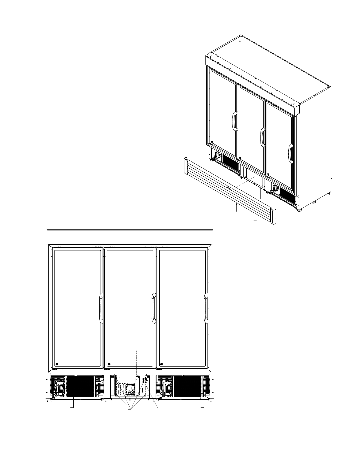
UNLESS OTHERWISE SPECIFIED
DIMENSIONS ARE IN INCHES.
R
UNLESS OTHERWISE SPECIFIED
R
CONTROL BOX VRL3B1A
The control box is located in the machine
compartment. The control box contains
electrical components such as the controller
board, relays, etc. See data sheet for additional
details on the wiring diagram.
REMOVE ACCESS PANEL,
LIFT AND PULL OFF
ELECTRICAL BOX LOCATED
FIXED ON THE FRONT
OF THE CASE
LH CONDENSING UNIT
UNSCREW COVER TO
ACCESS COMPONENTS
LOCATION ON THE FRONT
OF THE CASE PROVIDES
ACCESIBILITY TO ELECTRICAL
COMPONENTS WITHOUT THE
NEED TO UNSCREW THE BOX
HUSSMANN CORPORATION • BRIDGETON, MO 63044-2483 U.S.A.
RH CONDENSING UNIT
VRL Merchandisers
Page 32
32 ElEctrIcal / rEfrIgEratIon / controllEr
LOAD LIMIT LINE
54.75
Discharge Air Temperature
( Refrigeration Mode )
Controller Set Point
Range ( ° F )
Defrost Frequency
( per day )
Type of Defrost
Temp.
Termination
Failsafe
time ( min )
*** -10 to -8 ° F ( - 23 to - 22 ° C ) 3 Hotgas 55 ° F ( 12 ° C ) 50
-7 to 2 ° F (-21 to -16 ° C ) *** -10 to -8 ° F ( - 23 to - 22 ° C ) 3 Hotgas 47 ° F ( 8 ° C ) 40
15
20
25
30
VRL1B1A - Discharge Air Temp Sensor ( ° F ) @ 75 °F 55 % RH ( DOE )
Discharge Air Temperature
( Refrigeration Mode )
Controller Set Point
Range ( ° F )
Defrost Frequency
( per day )
Type of
Defrost
Temp.
Termination
Failsafe
Time ( min )
VRL1B1A Frozen Food - DOE 0 *** -10 to -8 ° F ( - 23 to - 22 ° C ) 3 Hotgas 55 ° F ( 12 ° C ) 50
VRL2B1A Frozen Food - DOE ´-7 to 2 ° F (-21 to -16 ° C ) *** -10 to -8 ° F ( - 23 to - 22 ° C ) 3 Hotgas 47 ° F ( 8 ° C ) 40
VRL3B1A Frozen Food - DOE ´-7 to 2 ° F (-21 to -16 ° C ) *** -10 to -8 ° F ( - 23 to - 22 ° C ) 3 Hotgas 60 ° F ( 15 ° C ) 40
Model Product Application
Notes *** :
1) Controller Set point from factory is - 8 °F for VRL1B1A
2) Controller Set point from factory is - 10 °F for VRL2B1A.
3) Controller Set point from factory is - 10 °F for VRL3B1A.
Hussmann Controller Operation RTN
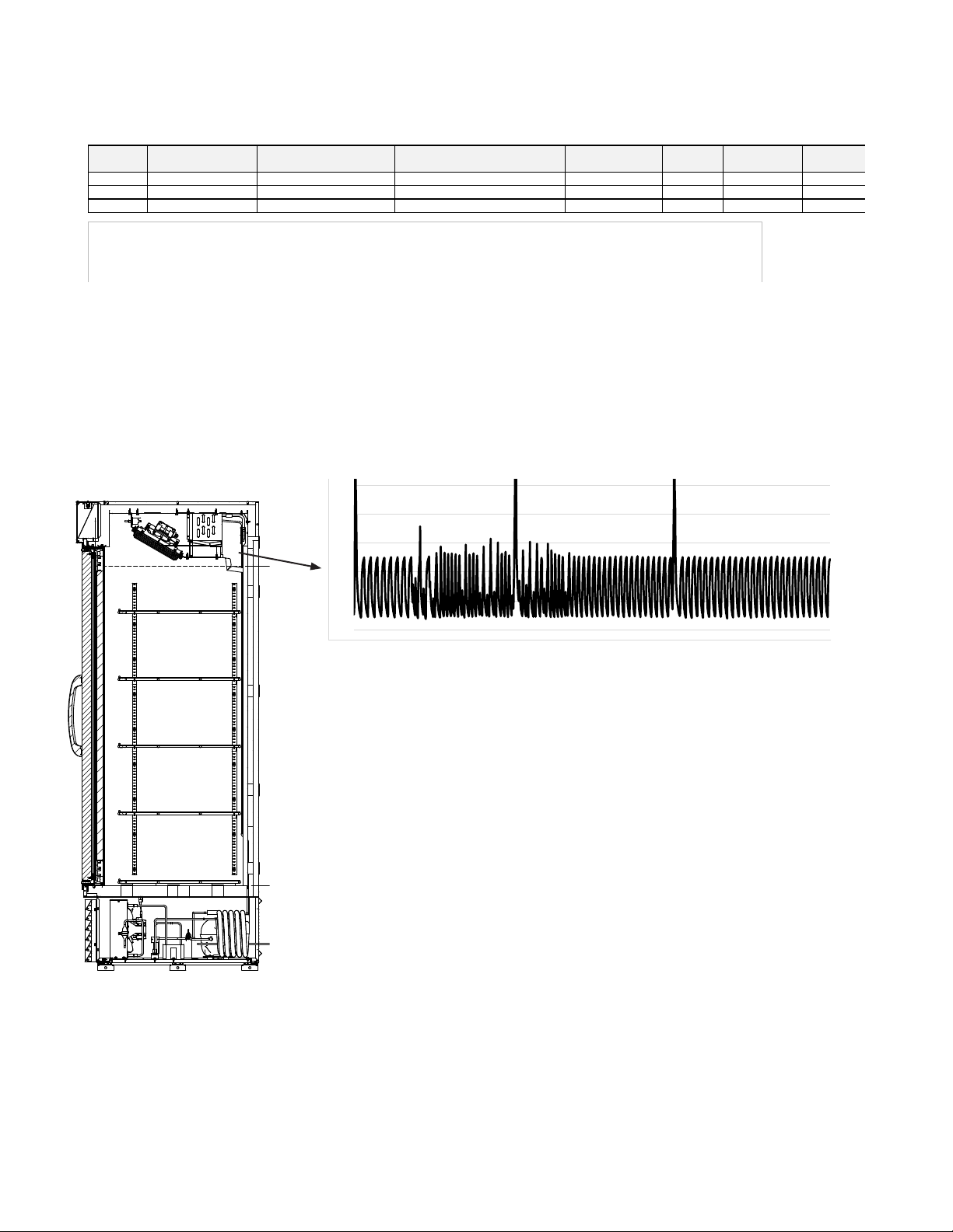
The Controller controls refrigeration temperature. This is factory installed in the control panel. Defrosts
are time initiated and temperature terminated for self contained. The defrost setting is factory set
as shown above. To ensure a thorough defrost, defrost must be terminated by the temperature
termination setting — not by time.
10
5
0
-5
-10
The graph shows what the discharge air sensor is reading. The case controller is
pre-programmed from the factory with a set point of -8° F. This merchandiser
holds product in all locations between 7° F and -6° F (evaluated under ASHRAE
72 method).
PN_3155541_D U.S. & Canada 1-800-922-1919 • Mexico 1-800-890-2900 • www.hussmann.com
Page 33
PN_3155541_D 33
LED
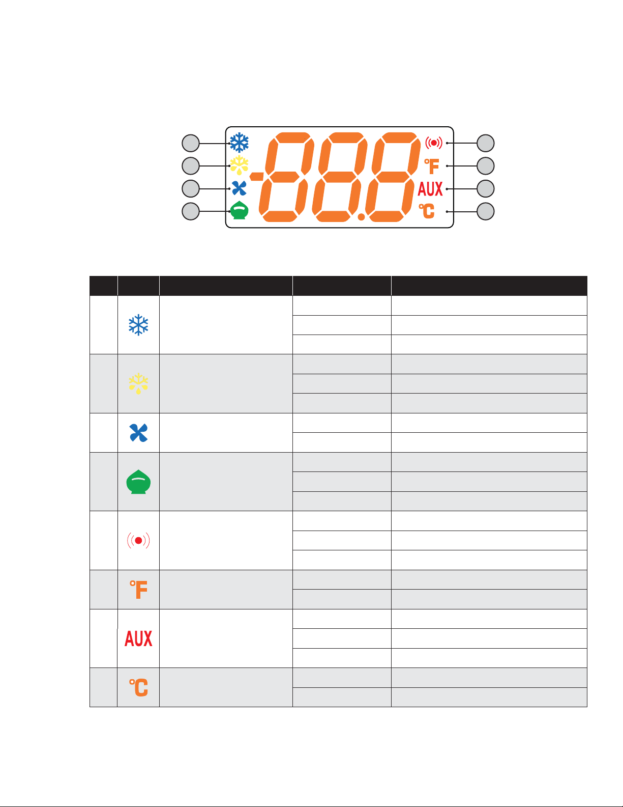
RTN400 family controllers will also function even if a keyboard has not been connected.
With KDEPlus or KDWPlus keyboards (which are the same and guarantee the same functions), the display will be as follows:
1
2
3
4
Meaning of LEDs:
No Icon LED Operation Meaning
Permanently on compressor on
1
2
3
Compressor
Defrost
Fans
Blinking Delay, protection or start-up blocked
OFF otherwise
Permanently on Defrost active
Blinking Activated manually or from Digital Input
OFF otherwise
Permanently on Fans active
OFF otherwise
5
6
7
8
Permanently on Energy Saving active
4
5
6
7
8
N.B.: When the instrument is powered on it performs a lamp test, during which time the display and LEDs will
Reduced SET / Economy
Alarm
°F readout
AUX
°C readout
flash for several seconds to check that they all function correctly.
Blinking Reduced setpoint active
OFF otherwise
Permanently on alarm active
Blinking Alarm acknowledged
OFF otherwise
Permanently on °F setting (dro =1)
OFF otherwise
Permanently on Aux output active and/or light on
Blinking Deep cooling on
OFF otherwise
Permanently on °C setting (dro = 0)
OFF otherwise
HUSSMANN CORPORATION • BRIDGETON, MO 63044-2483 U.S.A.
VRL Merchandisers
Page 34
34 ElEctrIcal / rEfrIgEratIon / controllEr
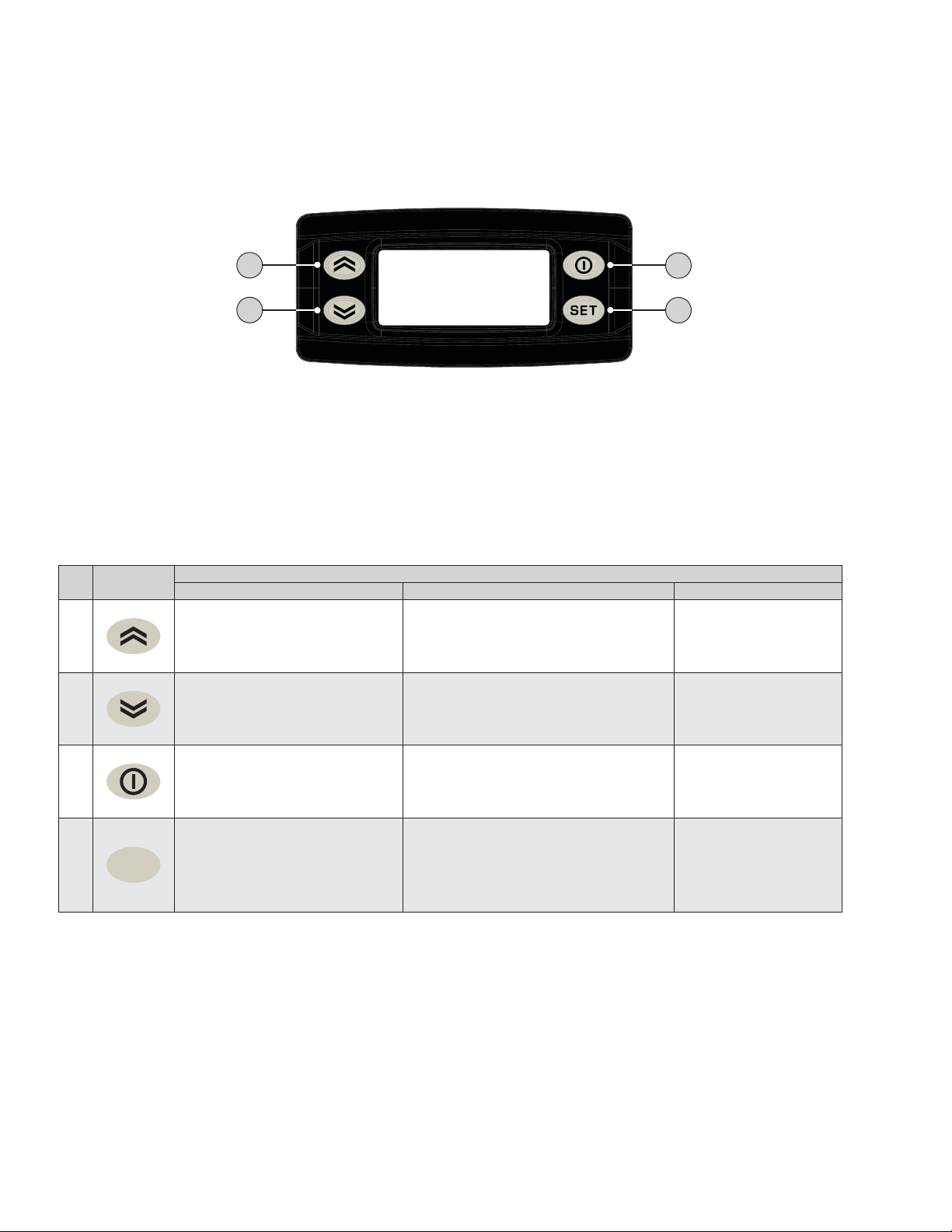
KDEPLUS BUTTONS
The KDEPlus keyboard has 4 keys, as shown in the illustration:
UP
1
DOWN SET
Each key has a different function depending on whether it is:
• Pressed and released
• Pressed for at least 5 seconds
• Pressed and held at start-up
• Pressed in combination with another key.
KEYS
The following table summarizes the function of each key:
No Key
1
2
• Scrolls through menu items
• Decreases values
• Scrolls through menu items
• Decreases values
2
Pressed and released Press for at least 5 secs Start-up
Activates the Manual Defrost function
(from outside menus).
Function can be configured by the user
(from outside menus).
(see parameter H32)
Action
STANDBY or ESC
3
4
---
---
• Returns to the previous menu
3
4
set
level
• Confirms parameter value
• Displays any alarms
(if active)
• Opens Machine Status menu
• Confirms commands
Activates the Stand-by function
(from outside menus).
Opens the Programming Menu
(User and Installer parameters)
---
When pressed during
start-up it enables
the user to select the
application to be loaded.
PN_3155541_D U.S. & Canada 1-800-922-1919 • Mexico 1-800-890-2900 • www.hussmann.com
Page 35
PN_3155541_D 35
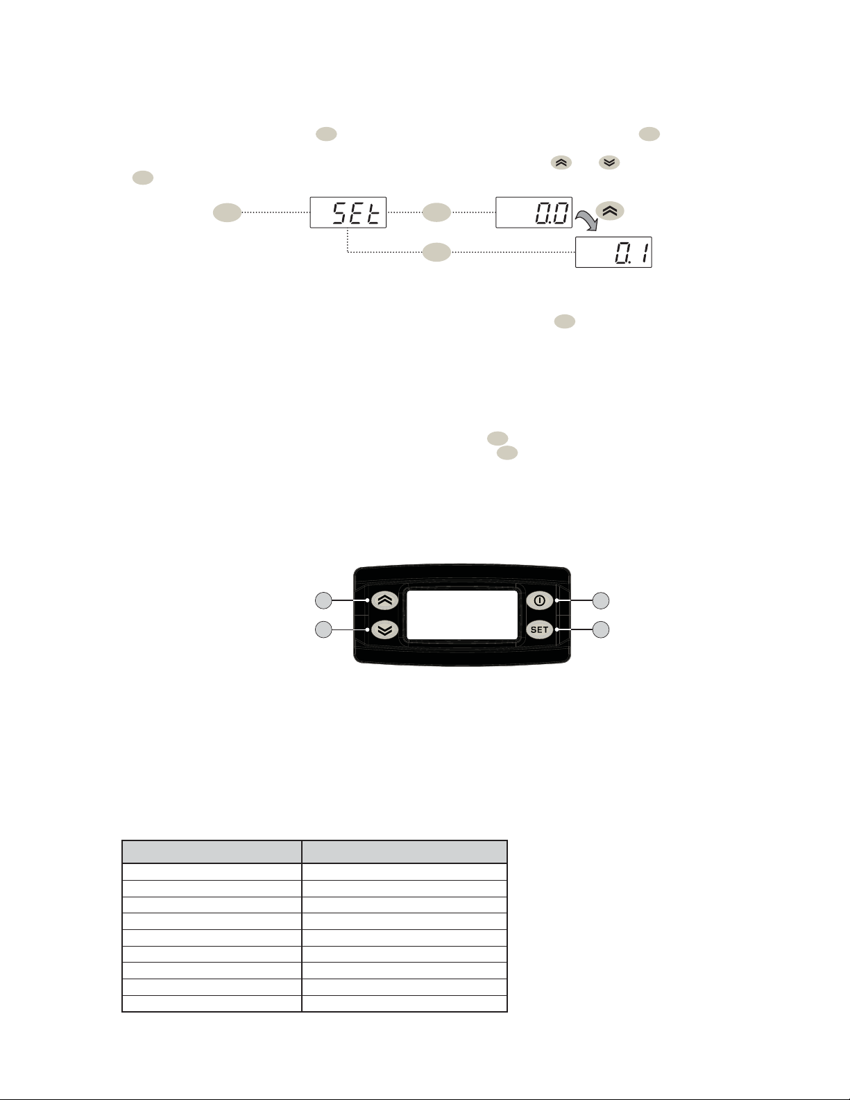
SETPOINT: SETTING AND EDIT LOCK
To display the Setpoint value, press the
set
key to enter the “Machine Status” menu, then press the
set
key again when the “SEt”
label is displayed.
The Setpoint value appears on the display. To change the Setpoint value, press the and keys within 15 seconds.
Press
set
to confirm the modification.
set
set
set
It is possible to disable the keypad on this device.
The keypad can be locked by programming the “LOC” parameter appropriately.
With the keypad locked, you can still access the “Machine Status” menu by pressing
set
to display the Setpoint, but you cannot edit
it. To disable the keypad lock, repeat the locking procedure.
DISPLAY PROBES VALUE
To display the value read by probes connected to the device, press the
set
key and enter the “Machine Status” menu, then press
the key again when one of the probe-related labels “Pb1...Pb5” press the
set
key again. The value measured by the associated
probe will appear on the display.
NOTE: The displayed value is read-only and cannot be modified.
SETPOINT: SETTING AND EDIT LOCK
To display the Setpoint value, press the
label is displayed.
The Setpoint value appears on the display. To change the Setpoint value, press the and keys within 15 seconds.
Press
to confirm the modification.
set
set
set
key to enter the “Machine Status” menu, then press the
set
set
set
It is possible to disable the keypad on this device.
The keypad can be locked by programming the “LOC” parameter appropriately.
With the keypad locked, you can still access the “Machine Status” menu by pressing
it. To disable the keypad lock, repeat the locking procedure.
DISPLAY PROBES VALUE
To display the value read by probes connected to the device, press the
the key again when one of the probe-related labels “Pb1...Pb5” press the
probe will appear on the display.
NOTE: The displayed value is read-only and cannot be modified.
KDEPLUS BUTTONS
The KDEPlus keyboard has 4 keys, as shown in the illustration:
set
key and enter the “Machine Status” menu, then press
set
key again. The value measured by the associated
set
to display the Setpoint, but you cannot edit
key again when the “SEt”
UP
1
KEY-ACTIVATED FUNCTIONS
All models have the UP key set to enable the “Manual Defrost” function.
The DOWN and ESC keys can also be set to activate any other function required by the user.
The parameters for configuring the two keys are:
• H11 = DOWN key configuration
• H33 = ESC key configuration
The values that can be set apply to both keys and the functions that can be activated are:
DOWN SET
2
H32/H33 value Function to enable
0 disabled
1 defrost
2 reduced set
3 Light
4 Energy saving
5 AUX
6 Stand-by
7 Deep cooling cycle
8 Start/end defrost
STANDBY or ESC
3
4
HUSSMANN CORPORATION • BRIDGETON, MO 63044-2483 U.S.A.
VRL Merchandisers
Page 36

36 MaIntEnancE
MAINTENANCE
To reduce the risk of fire, electrical shock or
injury when cleaning this merchandiser:
• Unplug the merchandiser before cleaning;
• Keep all liquids away from electrical and
electronic components;
• Do not use any mechanical device or other
means to speed the defrost process, except
as recommended by the manufacturer.
CARE AND CLEANING
Long life and satisfactory performance of
any equipment is dependent upon the care it
receives. To ensure long life, proper sanitation
and minimum maintenance costs, this unit
should be thoroughly cleaned, all debris
removed and the interiors washed down.
Cleaning often will control or eliminate odor
buildup. Frequency of cleaning is dependent
on usage and local health requirements.
Interior Surfaces
do not use AmmoniA-bAsed products to
cleAn light shields. never use AbrAsive
cleAnsers or scouring pAds.
The interior surfaces may be cleaned with most
domestic detergents and sanitizing solutions
with no harm to the surface. Always read and
follow the manufacturer’s instructions when
using any cleaning product.
Inspect all LED connections and plug/
receptacles for signs of arcing. Replace any
component that shows signs of arcing. Make
sure all unused receptacles have close-off covers
securely attached.
CLEANING UNDERNEATH THE CASE
The case can be moved to facilitate cleaning.
Unplug the merchandiser, and move it out if
the way in order to sweep and mop the area
underneath the case. Brush away all dirt and
litter from the area. Ensure there is no dirt
build up around the bottom of the case or near
the intake or exhaust.
Do not use HOT water on COLD glass surfaces.
This can cause the glass to shatter and could
result in personal injury. Allow glass fronts,
ends and service doors to warm before applying
hot water.
Exterior Surfaces
The exterior surfaces must be cleaned with a
mild detergent and warm water to protect and
maintain their attractive finish.
never use AbrAsive cleAners or scouring
pAds. never use cAustic sodA, kerosene,
gAsoline, thinner, solvents, detergents,
Acids, chemicAls or AbrAsives. do not use
AmmoniA-bAsed cleAners on Acrylic pArts.
PN_3155541_D U.S. & Canada 1-800-922-1919 • Mexico 1-800-890-2900 • www.hussmann.com
Page 37

PN_3155541_D 37
Do NOT Use:
• Abrasive cleansers and scouring pads,
as these will mar the finish.
• Coarse paper towels on coated glass.
• Ammonia-based cleaners on acrylic parts.
• A hose on lighted shelves or submerge the
shelves in water.
• Solvent, oil or acidic based cleaners on any
interior surfaces.
• A hose on rail lights, canopy lights or any
other electrical connection.
Do:
• First turn off refrigeration, then disconnect
electrical power.
• Remove product and loose debris.
• Rinse with hot water, but do NOT flood.
• Allow merchandiser to dry before resuming
operation.
• Wipe down lighted shelves with a damp
sponge or cloth so that water does not enter
the light channel.
submerge shelves in wAter.
do not use A hose or
• After cleaning is completed, restore power
and turn on the merchandiser.
Product will be degraded and may spoil if
allowed to sit in a non-refrigerated area.
Cleaning Shelves
Shelves and shelf clips are easily removed for
cleaning the interior as well as the shelves
themselves.
• Thoroughly clean all surfaces with soap
and hot water. do not use steAm or
high wAter pressure hoses to wAsh the
interior. these destroy merchandiser’s
sealing causing leaks and poor
performance.
• Take care to minimize direct contact between
fan motors and cleaning or rinse water.
HUSSMANN CORPORATION • BRIDGETON, MO 63044-2483 U.S.A.
VRL Merchandisers
Page 38
38 MaIntEnancE
REVISION HISTORY
REV ECN DATE REVISION DESCRIPTION REV BY CHKD BY APPR BY
CLEANING CONDENSER COILS
The coil should be cleaned at least once each month to maintain peak operating efficiency.
A dirty coil slows product cooling significantly and increases energy consumption by as much
as 20 percent. Dirt buildup on coils can also cause the compressor to lock up damaging the
condenser unit.
To clean the coils, use a vacuum cleaner with a wand attachment and a soft (non-metallic) brush
to remove dirt and debris. Do not bend coil fins. Always wear gloves and protective eye wear
when cleaning near sharp coil fins and dust particles.
NEVER USE SHARP OBJECTS AROUND COILS. Use a soft brush or vacuum brush to clean
debris from coils. Do not puncture coils! Do not bend fins. Contact an authorized service technician if a
coil is punctured, cracked, or otherwise damaged.
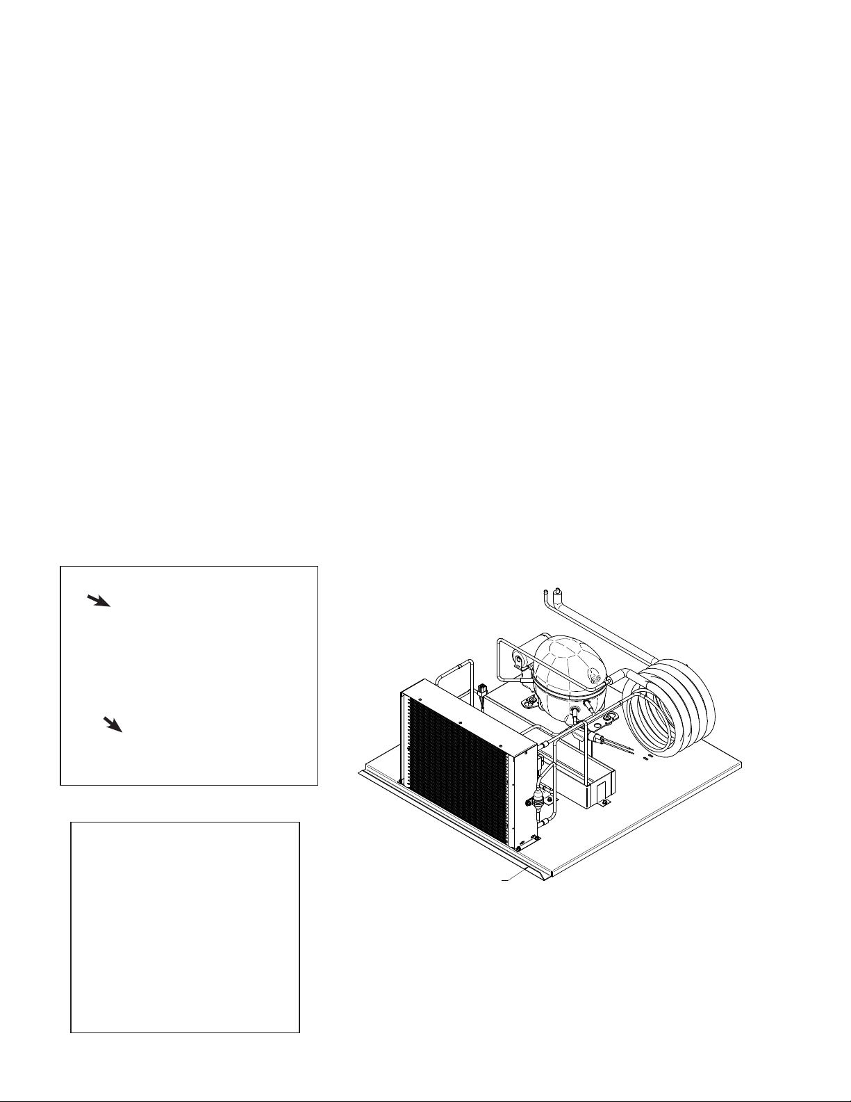
All VRL models have the same access panel design for commonality between merchandisers. To
remove the front grille perform the following steps:
1. Lift up, and pull off the grille.
2. Remove the holding bracket to release the condensing unit base. Once the condensing unit
base is free, you can slide it out for service. Use base flange to pull out the condensing unit.
Pulling on refrigeration lines or others parts will cause damage to the unit.
VRL1B1A
Refrigeration
Unit
USE CU BASE FLANGE TO SLID
THE CONDENSING UNIT OUT
Lift up, and pull off the grille.
Front
FRONT
NOTE:
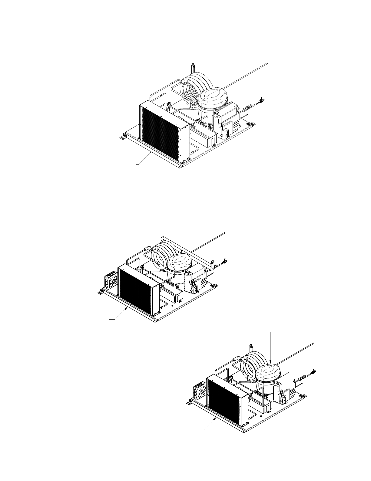
Condensing unit view for 2-door and 3-door models are shown
on the next page.
Front Grille
PN_3155541_D U.S. & Canada 1-800-922-1919 • Mexico 1-800-890-2900 • www.hussmann.com
Page 39
PN_3155541_D 39
REVISION HISTORY
REV ECN DATE REVISION DESCRIPTION REV BY CHKD BY APPR BY
LH CONDENSING UNIT
REVISION HISTORY
REV ECN DATE REVISION DESCRIPTION REV BY CHKD BY APPR BY
RH CONDENSING UNIT
VRL2B1A Condensing Unit
USE CU BASE FLANGE TO SLID
Front
THE CONDENSING UNIT OUT
VRL3B1A Condensing Units
Use CU base ange to slid
USE CU BASE FLANGE TO SLID
out the condensing unit
THE CONDENSING UNIT OUT
LH CONDENSING UNIT
RH CONDENSING UNIT
Use CU base ange to slid
out the condensing unit
HUSSMANN CORPORATION • BRIDGETON, MO 63044-2483 U.S.A.
VRL Merchandisers
Page 40
40 MaIntEnancE
3. Use a soft hand brush attachment on a
vacuum to remove accumulated dust and
debris.
Consult an authorized service technician
if more extensive cleaning is needed. If the
refrigeration unit is damaged, it can be
replaced with a new unit.
TIPS AND TROUBLESHOOTING
There are a few simple things to check before
calling for service:
1. Product not cold? Refrigeration unit requires
24 hours at initial startup to cool down to
operating temperature with
loAded in merchandiser. Ask when
no product
merchandiser was stocked, and what the
usage has been. It may take 30 minutes or
more for product to chill following stocking.
2. Check the door and door seal for air leaks.
3. Power Supply:
Is the unit plugged in?
Is there power to the unit?
4. Location
What are the ambient conditions—
temperature and humidity, direct sun,
nearby source of heat, such as oven or grill?
Is the unit level? Has the unit been moved
recently?
IMPORTANT
INFORMATION
For prompt service when contacting the
factory, be sure to have the case model and
serial number from the case serial plate.
— LOCK OUT / TAG OUT —
To avoid serious injury or death from electrical
shock, always disconnect the electrical power
at the main disconnect when servicing or
replacing any electrical component. This
includes, but is not limited to, such items as
doors, lights, fans, heaters, and thermostats.
ADJUSTING CLOSING TORQUE
Adjust closing torque by turning the bottom
hinge pin in the direction the door closes. Use
1
a
/2 in. (13 mm) wrench. Turn the hinge pin
until the door closes on its own, usually to
1
2clicks or
/2 turn.
DO NOT over-torque the hinge spring
assembly. Excessive torque (over 1 full turn)
will result in damage to the spring assembly
and/or door. If door does not close on its
own after one full turn (5 clicks), look for
obstructions causing the door to hang up.
5. Shelves and Stocking
Are the standard shelves in the correct places?
Is the product stocked properly?
Is the bottom shelf at the proper location?
6. Confirm that the defrost schedule is properly
set.
Adjusting Closing Torque
PN_3155541_D U.S. & Canada 1-800-922-1919 • Mexico 1-800-890-2900 • www.hussmann.com
Page 41
PN_3155541_D 41
ADJUSTING DOOR SAG
To adjust door sag (saw-tooth effect from door
to door), loosen the two hinge plate mounting
screws using a Torx Plus no. 27 bit. Adjust
hinge plate as needed, then tighten the screws.
Hinge Plate
Mounting
Screw
Loosen both
hinge plate
mounting
screws.
Adjusting Door Sag
INNOVATOR DOOR MAINTENANCE
As part of an ongoing maintenance program
for Innovator Doors, Hussmann recommends
that the items below be checked annually.
a) Proper door closing torque.
b) Gasket performance (check for tearing and
proper sealing).
c) Check the top hinge pin to ensure the pin is
properly seated and not bent.
d) Check the bottom hinge plate for excessive
wear (worn cam teeth).
e) Proper operation of hold open brackets.
1. Check the doors for proper closing torque:
Torque adjustment, if needed, should be
performed “one click” at a time. A “zero”
torque door should not require more than 4
clicks.
If the torque cam and hinge socket are
severely rusted, both components should be
replaced.
A severely rusted cam / socket assembly will not
hold torque. Rust on the cam socket assembly is
usually caused by one of the following:
• High humidity conditions > ASHRAE Type I
• Cycling of the frame heaters
Note 1: A rusted torque cam / socket assembly
can cause excessive wear on the torque rod’s
spacer and sleeve bearing. The result is a door
that can “seat” farther down the rod assembly
to the point that it causes binding at the hold
open bracket.
It can also cause the top hinge pin’s sleeve
bearing to deform. If the door is seated too far
down the torque rod assembly, it most likely
damaged the top hinge pin sleeve bearing. If
the pin is not bent, replacing the pin’s nylon
sleeve bearing will be sufficient. Although the
torque rod assembly’s sleeve bearing and spacer
are replaceable, we recommend that a severely
rusted torque rod assembly be replaced.
HUSSMANN CORPORATION • BRIDGETON, MO 63044-2483 U.S.A.
VRL Merchandisers
Page 42

42 MaIntEnancE
Innovator Door Maintenance Continuted...
2. Inspect door gaskets:
• Check for tearing gaskets
• Make sure the gasket’s dart is properly
seated into the door’s gasket groove.
3. Inspect the top hinge assembly for excessive
movement at the top hinge socket.
• By design, the door will have a small, but
discernible amount of movement at the
top hinge pin / hinge plate socket joint.
If excessive movement is detected, the
hinge pin assembly should be inspected
to ensure that the hinge pin is not bent
(refer to note #1).
4. Inspect hold open bracket:
• Open the door to the “hold open”
engagement position. The “hold open”
bracket should retain the door.
• If the bracket fails to retain the door,
replace the bracket and the shoulder
screw.
5. If a door passes the three “open / close”
tests, and there is no excessive movement at
the top hinge pin, then it is highly unlikely
that any components require replacement.
PN_3155541_D U.S. & Canada 1-800-922-1919 • Mexico 1-800-890-2900 • www.hussmann.com
Page 43
PN_3155541_D 43
Self-Contained Refrigeration Equipment Maintenance Check List
** * * * Warranty does not coverissues caused by improper installation orlackof basic preventative maintenance. * * * * *
Record startingdate
Store Name and Number
Store Address
Unit Model Number
Contractor/Technician
Unit Serial Number
Technician
PM date
PMactivity-For visual inspection items, denote "ok or
complete" in the column to rightwhen PM has been
performed. Formeasured data requested, recorddata
requested in the appropriate column to the right)
Check in with store manager, record any complaints or issues
they have with unit.
Look unit over for any damage,vibrationsorabnormalnoise.
Verify unit is level side to side and front to rear.
Confirm refrigerant lines properly are secured and not touching
or rubbing other lines, wires or frame work.
Verify fan motors and motor mounts are tight.
Confirm fan blade/s are tight and not rubbing or hitting.
Make sure all electrical connections, factory and field, are tight.
Verify electricalconnections at lamps are they secure and dry.
Check for and replace any frayed or chaffed wiring.
Check all electrical wiring make sure it is secured and not on
any sharp edges or hot lines.
Check for air disturbances externall to the unit. Heat and air
registers,fans, and doors etc.
Check for water leaks.
Clean evaporator coil/s and fan blade/s. Do not use an acid
base cleaner. Rinse off any cleaner residue.
Clean discharge air honeycombs orgrilles. Donot use an acid
base cleaner. Rinseoff any cleaner residue.
Clean condenser coil/s and fan blade/s. Do not use an acid base
Cleaner. Rinse off any cleaner residue.
Clean condensate drain pan and drain line.
Verify condensate drain lines are clear andfunctioning.
Record voltage reading at unit with unit off?
Verify condenser and evaporator fans are working.
Record condenser air inlet temperature
Record condenser air outlet temperature
Is condenser air inlet or air exhaust restricted or recirculating?
Use a handheld propane leak detector ("sniffer") to check
for refrigerant leaks.
Record voltage reading with unit running.
Record compressor amp draw.
Record defrost heater voltage and amp draw.
Record anti-sweat heater voltage and amp draw.
Record case product temperature.
Record unit discharge air temperature.
Record unit return air temperature.
Record ambient conditions around unit (wet bulb temperature
and dry bulb temperature).
Check product loading, do not load beyond the units load limits.
Verify clearances on sides/back of unit.
Check unit controller for proper operation. See controller or 1/0
Manual for proper controller operation.
Confirm door switches function.
Verify unit doors and lids work and are sealed correctly.
Verify that all the panels, shields and covers are in place.
Quarterly
x
x
x
x
x
x
x
x
x
x
x
x
x
x
x
x
x
x
x
x
x
x
x
x
x
x
Semi-
Annually
x
x
x
x
x
x
x
x
x
x
x
Ql
Q2
Q3 Q4
Ql
Q2
Q3 Q4
Technician Notes:
Form HSCW03 Rev-29 OCTOBER13
HUSSMANN CORPORATION • BRIDGETON, MO 63044-2483 U.S.A.
VRL Merchandisers
Page 44
44 sErvIcE
SERVICE
REPLACING DISPLAY LAMP
Note: This procedure applies to all VRL models
(1-door model is shown in the photos)
1. Disconnect power to the merchandiser.
Remove the screws at the top of the unit
display.
2. Remove the top panel.
Display Slides out to access Wireway
3. Remove the merchandiser’s plexiglass panel.
REPLACING SHELF LAMPS
1. Disconnect power to the merchandiser. The
LED fixtures are located behind the top of the
door frame.
LED Location
2. Remove the screws and disconnect the LED
fixture from the merchandiser.
4. Remove the cover display in order to have
access to the LED fixture harness.
3. Replace the LED with like fixture.
5. Replace the LED with like fixture, and
re-attach connection.
6. Replace the display panel cover.
7. Return power to the merchandiser.
4. Return power to the merchandiser.
PN_3155541_D U.S. & Canada 1-800-922-1919 • Mexico 1-800-890-2900 • www.hussmann.com
Page 45
PN_3155541_D 45
Drain
Tube
Channel
Figure B
Figure B
Figure C
Drain
Tube
Channel
Evap Fan
Harness
Figure B
Figure D
Figure C
Figure F
Figure B
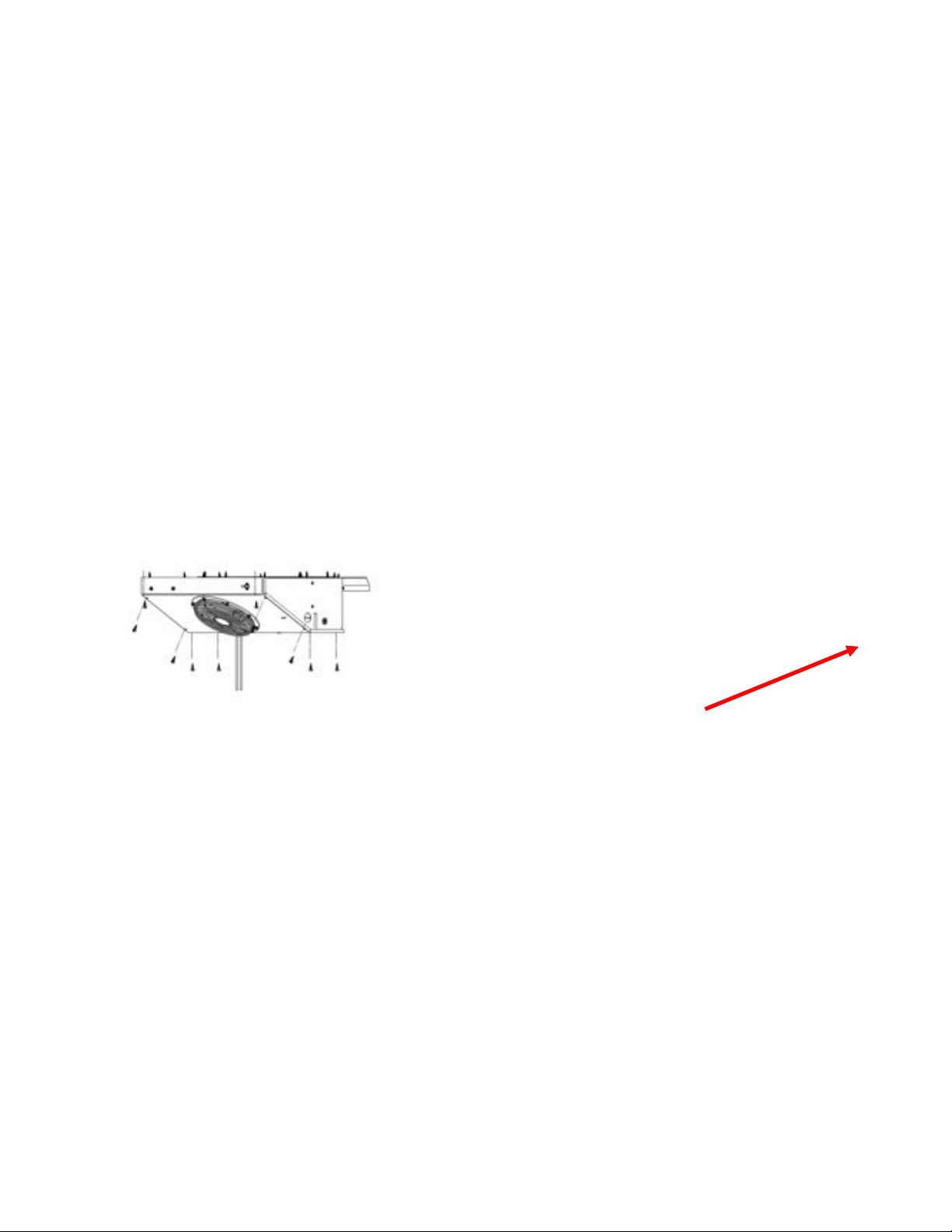
REPLACING EVAPORATION PAN HEATER
Note: This procedure applies to all VRL models
(1-door model is shown in the photos)
Remove screws from Fan Plenum. See gure for
1.
screws location and drain tube channel. See Figure A
Tilt the fan plenum to access to the evap. fan harness
2.
connection as well as the light switch.
Identify and disconnect the evap. fan harness.
3.
Remove Fan plenum. See Figure B
4.
Identify evap. pan heater leads. See Figure C.
5.
Disconnect heater leads from harness
6.
Pass heater leads through bushing.
7.
Unscrew hexagonal head screws in order to release
8.
the evaporator pan assembly. See Figure E.
See Figure F for the evaporator pan assembly example.
9.
Remove aluminum foil and old wire heater.
10.
Figure A
See Figure G, which shows the sheet metal pan.
Figure B
Figure C
Figure C
Evap Fan
Harness
Figure F
Figure F
Figure D
Figure D
Figure E
Figure E
HUSSMANN CORPORATION • BRIDGETON, MO 63044-2483 U.S.A.
Figure G
Figure G
VRL Merchandisers
Page 46
46 sErvIcE
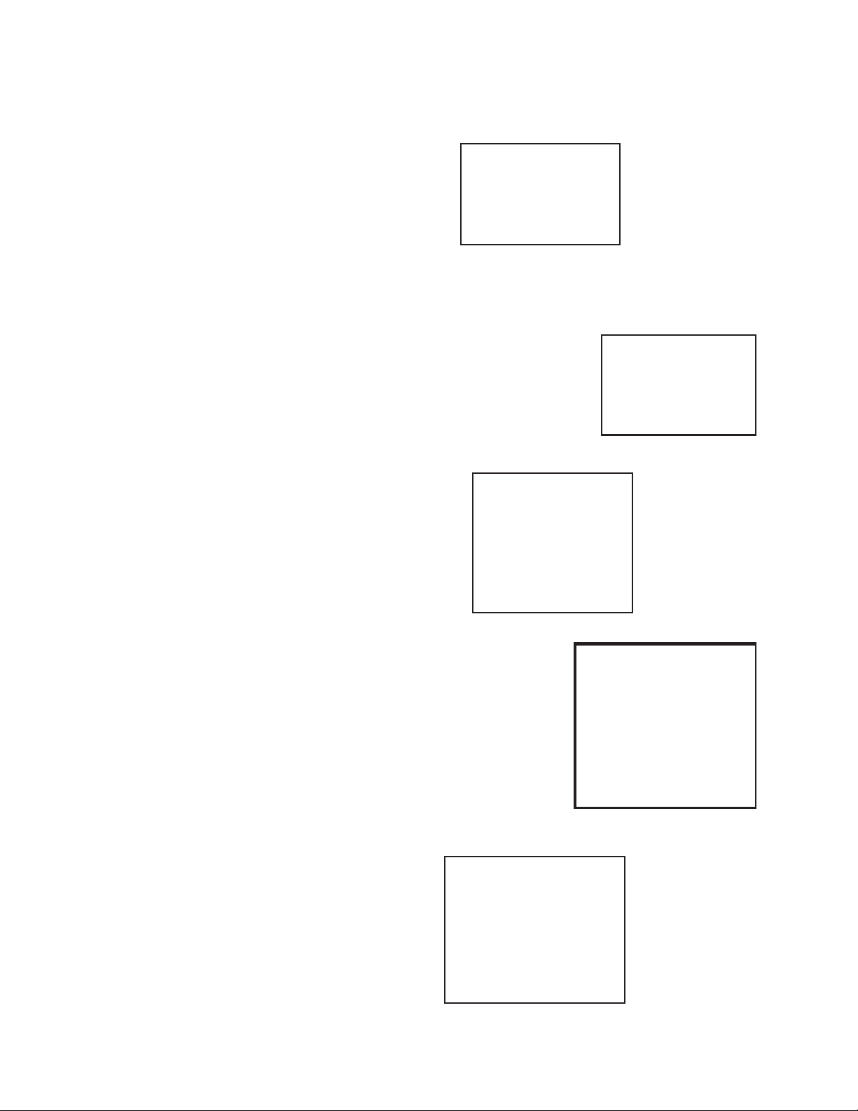
FRAME HEATER REPLACEMENT
Always turn off power to the case before working
on any electrical components. The old wireway
covers must be removed to access the door
frame heaters. Begin by inserting a putty knife
into the groove between the wireway cover and
fiberglass frame, about an inch (25 mm) away
from joints in the frame as shown. Carefully
begin to pry off the cover.
Use a second putty knife or flat head
screwdriver to hold up the cover as shown in
A. Pry the remainder of the section up, using
putty knife only, until the entire cover is off
and the frame heater inside the door frame is
exposed as shown in B.
Door frame heaters may now be replaced.
A
B
During installation, the white portion of the
heater should not come in contact with itself.
The heater should be installed so that only one
white portion of the wire enters the raceway.
The other portion entering the raceway will be
the black lead wire.
Once the heater wire is connected, check
resistance (ohm reading) before replacing
wireway covers. This will ensure that heater
wire was not broken during installation. Wiring
diagrams are shown on the last pages of this
manual.
After covers are reinstalled, turn power on and
verify that heaters are working properly.
C
D
E
PN_3155541_D U.S. & Canada 1-800-922-1919 • Mexico 1-800-890-2900 • www.hussmann.com
Page 47
PN_3155541_D 47
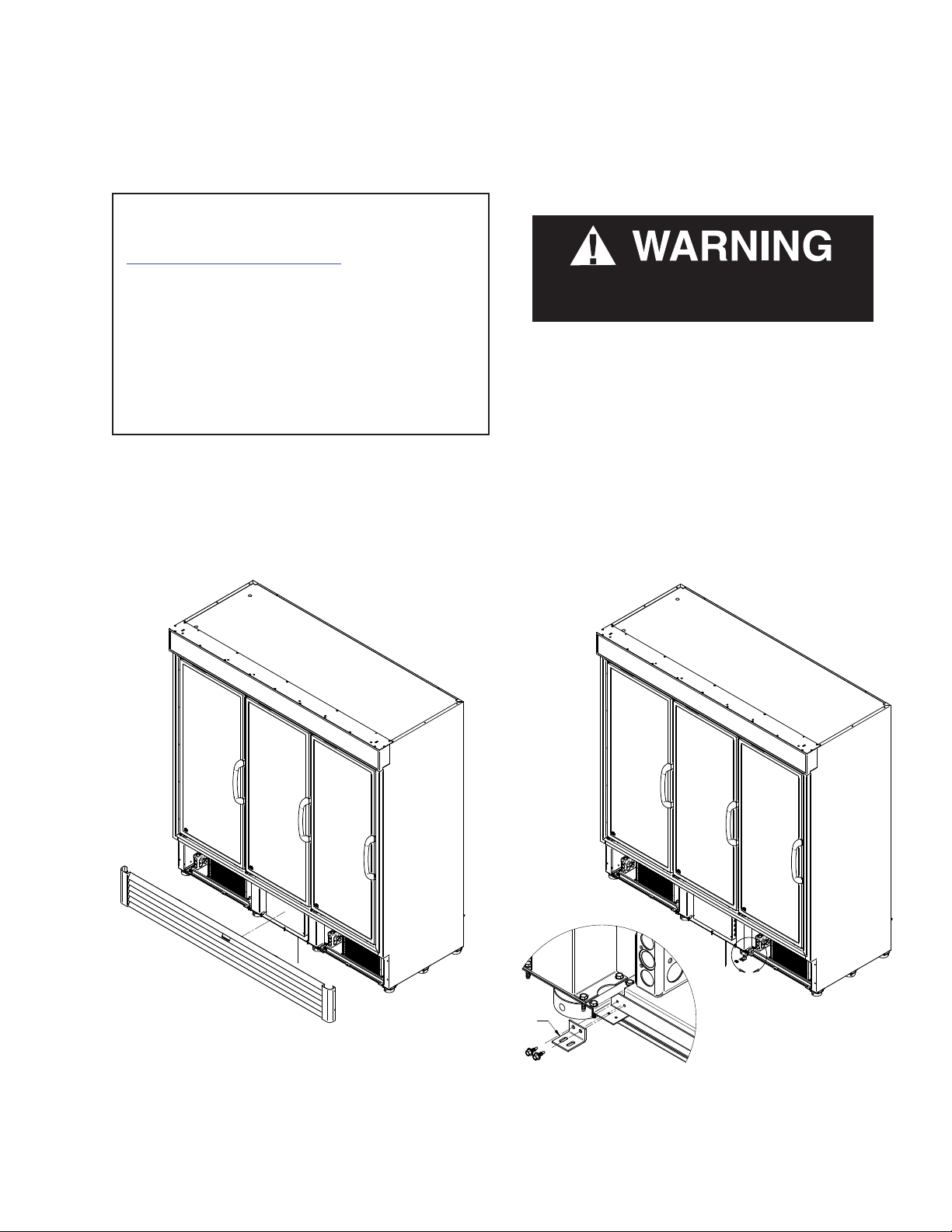
REPLACING INVERTER
(Applies only for VRL2 and VRL3)
Unplug the power cord before servicing.
Parts may be ordered at Hussmann’s Performance
Parts e-store:
https://parts.hussmann.com/
or
Call toll free: 855-487-7778
Product will be degraded and may spoil if
allowed to sit in a non-refrigerated area.
Required Tools:
• Screwdriver / Philips Tip
• 1/4" Allen Wrench
Remove product and place in a refrigerated area.
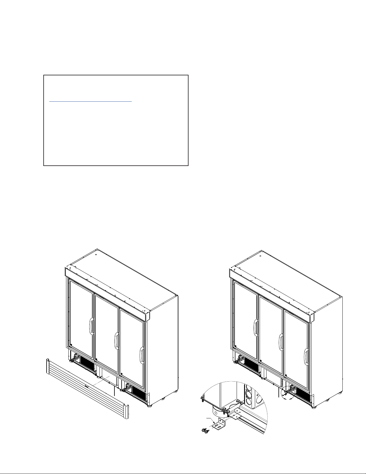
1.
Make sure the power is off to the case.
2. Make sure there is no voltage in the refrigerator. Remove rear lower panel as shown below.
REMOVE CONDENSING UNIT
STOPPER
VRL3B1A Shown
HUSSMANN CORPORATION • BRIDGETON, MO 63044-2483 U.S.A.
A
VRL Merchandisers
Page 48
48 sErvIcE
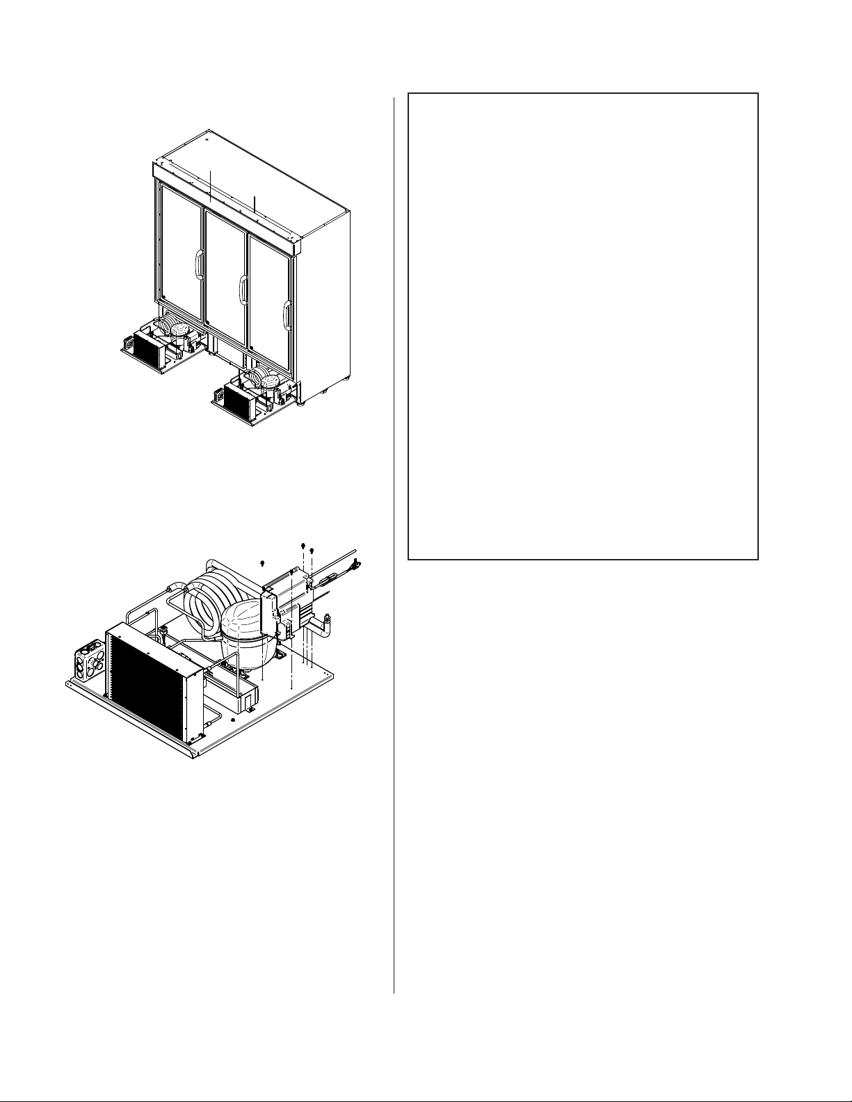
3. Remove motor screws.
4. Disconnect inverter harness and ground.
INVERTER BOARD DIAGNOSTICS
Diagnostics:
The Fullmotion CF10B Inverter has two
diagnostics methods, by visual light emission
using a LED indication, or by serial
communication protocol.
LED indication:
The LED diagnostics function helps service
technicians to diagnose possible fault
components by blinking a LED inside the box
in different patterns. Basically, it indicates if
there is a problem with compressor CF10B
Inverter or Thermostat. The table below
describes the failure modes:
5. Take off the inverter screws.
6. Replace inverter with the new one.
7. Reverse the process, and make sure screws
are hand-tight and everything is working
properly.
PN_3155541_D U.S. & Canada 1-800-922-1919 • Mexico 1-800-890-2900 • www.hussmann.com
Page 49
PN_3155541_D 49
REPLACING CONDENSER MOTOR
Unplug the power cord before servicing.
Parts may be ordered at Hussmann’s Performance
Parts e-store:
https://parts.hussmann.com/
or
Call toll free: 855-487-7778
Required Tools:
• Screwdriver / Philips Tip
• 1/4" Allen Wrench
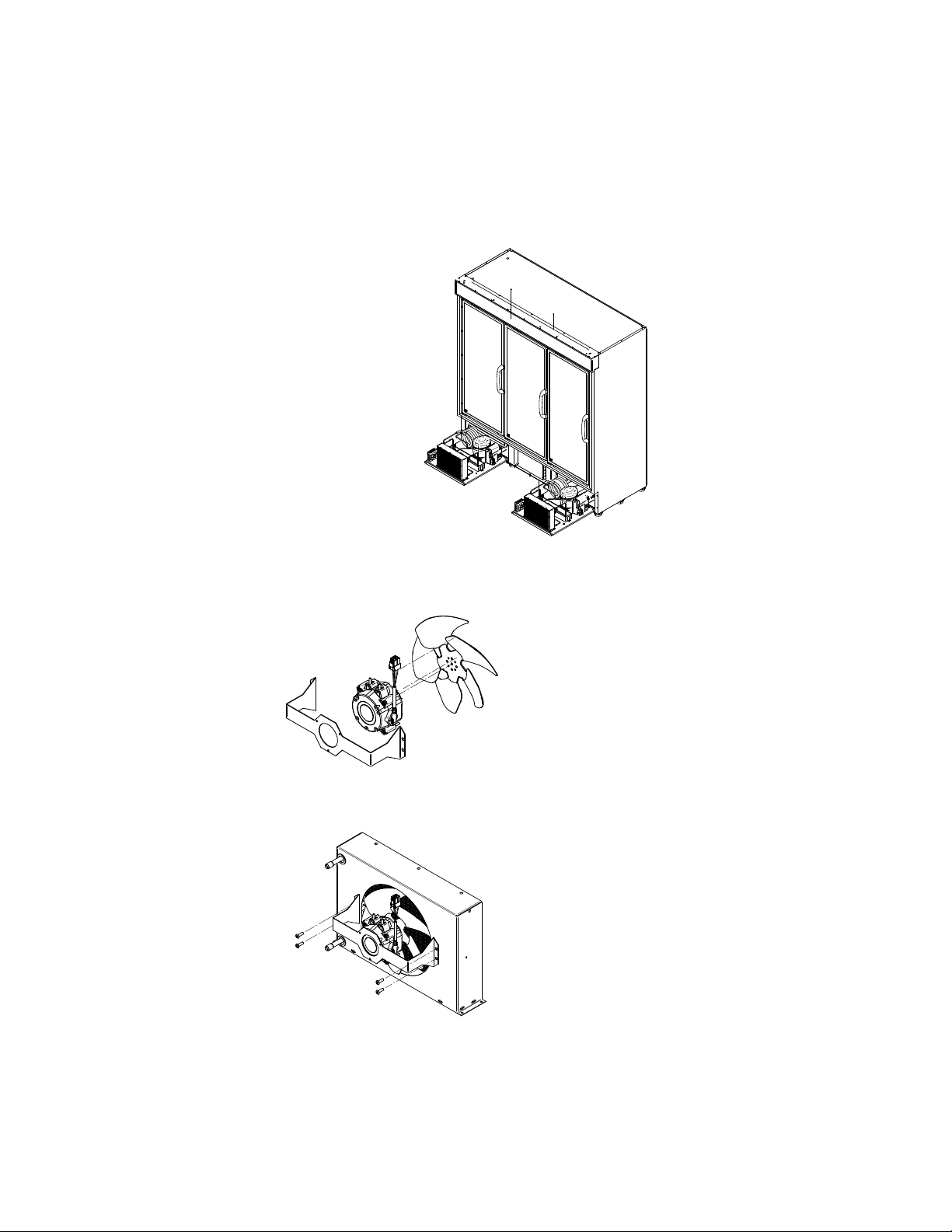
1. Remove product and place in a refrigerated area. Make sure the power is off to the case.
2. Make sure there is no voltage in the refrigerator. Remove rear lower panel as shown in the
illustration.
3. Slide out the condensing unit. Be careful using the condensing unit base to pull it out. Make
sure not to stress or interfere with other parts.
REMOVE CONDENSING UNIT
VRL3B1A Shown
HUSSMANN CORPORATION • BRIDGETON, MO 63044-2483 U.S.A.
STOPPER
A
VRL Merchandisers
Page 50
50 sErvIcE
4. Disconnect condenser motor harness.
5. If a flexible extension is used, skip Step 6.
6. Release screws to partially remove venturi assembly.
7. Release screws to remove condenser fan assembly.
8. Release motor screws to get to motor / blade assembly.
9. Change failed part.
10. If the only damaged part is the motor, remove blade.
11. Reverse the process and make sure everything is in place and working.
PN_3155541_D U.S. & Canada 1-800-922-1919 • Mexico 1-800-890-2900 • www.hussmann.com
Page 51
PN_3155541_D 51
REPLACING COMPRESSOR
Unplug the power cord before servicing.
Parts may be ordered at Hussmann’s Performance
Parts e-store:
https://parts.hussmann.com/
or
Call toll free: 855-487-7778
Required Tools:
• Screwdriver / Philips Tip
• 1/4" Allen Wrench
• Copper Tubing Cutter
• Blow Torch
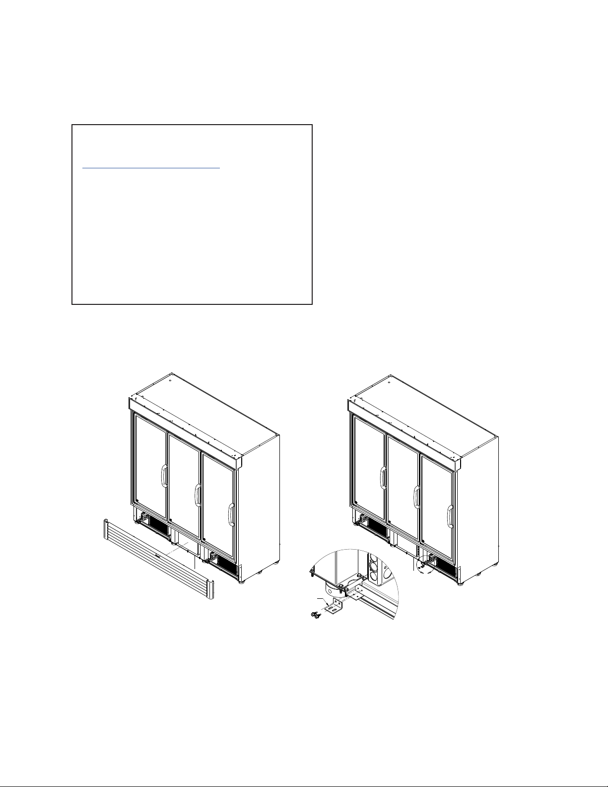
1. Remove product and place in a refrigerated area. Make sure the power is off to the case.
2. Make sure there is no voltage in the refrigerator. Remove lower panels.
A
REMOVE CONDENSING UNIT
3VRLB1A Shown
STOPPER
3. Make sure there is no refrigerant left in the system. Refer to Page 2-6 - Steps to Recover
Refrigerant.
HUSSMANN CORPORATION • BRIDGETON, MO 63044-2483 U.S.A.
VRL Merchandisers
Page 52
52 sErvIcE
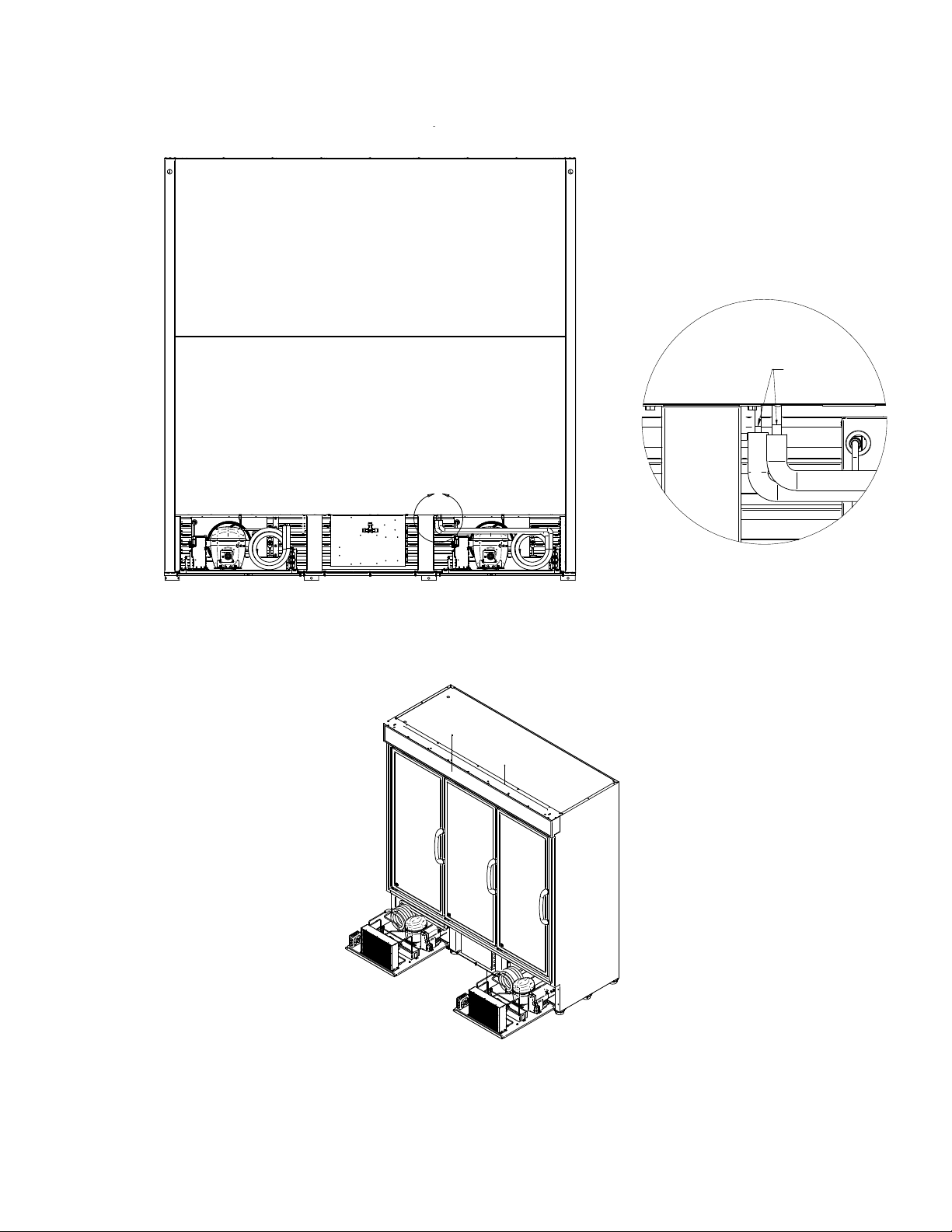
4. Remove welded joints that connect the
condensing units and the evaporator.
SEPARATE TUBES
DESOLDERING
B
DETAIL B
5. Slide out the condensing unit completely. Be careful using the condensing unit base to pull it
out. Make sure not to stress or interfere with other parts.
6. Disconnect all wires and harness from the compressor.
PN_3155541_D U.S. & Canada 1-800-922-1919 • Mexico 1-800-890-2900 • www.hussmann.com
Page 53
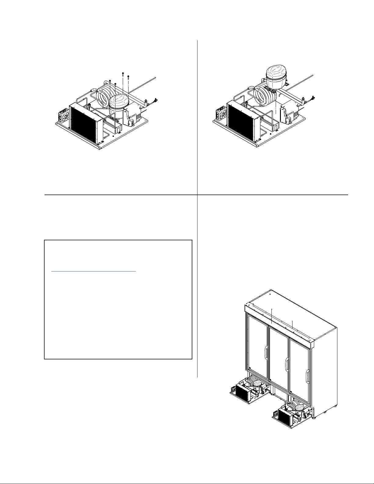
PN_3155541_D 53
7. Take off compressor screws.
REPLACING SOLENOID VALVES
8. Remove welded joints to the compressor
and replace with new compressor.
9. Reverse the process and make sure
everything is in place.
Unplug the power cord before servicing.
Parts may be ordered at Hussmann’s Performance
Parts e-store:
https://parts.hussmann.com/
Call toll free: 855-487-7778
or
Required Tools:
• Screwdriver / Philips Tip
• 1/4" Allen Wrench
• Copper Tubing Cutter
• Blow Torch
1. Remove product and place in a refrigerated
area. Make sure the power is off to the
case.
3. Make sure there is no refrigerant left in the
system.
4. Slide out the condensing unit. Be careful
using the condensing unit base to pull it
out. Make sure not to stress or interfere
with other parts.
2. Make sure there is no voltage in the
refrigerator. Remove rear lower panel.
HUSSMANN CORPORATION • BRIDGETON, MO 63044-2483 U.S.A.
3VRLB1A Shown
VRL Merchandisers
Page 54
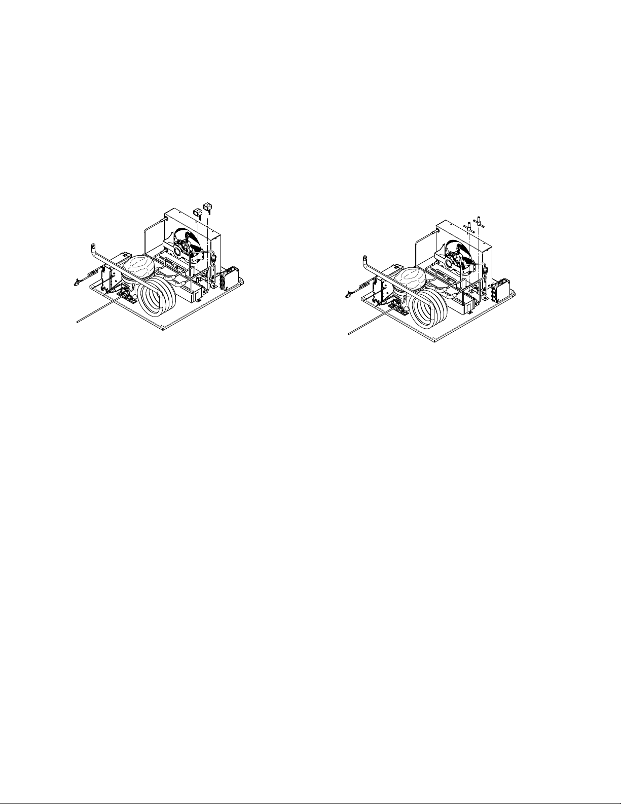
54 sErvIcE
5. Remove coil by pulling up and disconnect wires.
6. Release clamps and remove welded joints from the valves.
7. Replace solenoid valves.
8. Reverse the process and make sure everything is in place.
PN_3155541_D U.S. & Canada 1-800-922-1919 • Mexico 1-800-890-2900 • www.hussmann.com
Page 55

PN_3155541_D 55
TECHNICAL INFORMATION
Visual Description of R290 Replacement Parts
Main Switch
(3-door models)
Control RTN400
Main Switch
(1 & 2-door models)
Control Display KDE
Light Switch
Solid State Relay
Component parts are specifically chosen
for propane exposure and therefore non-
incendive and non-sparkling. Component
parts shall be replaced with identical
components, and servicing shall be done by
factory authorized service personnel only, so
as to minimize the risk of possible ignition
due to incorrect parts or improper service.
HUSSMANN CORPORATION • BRIDGETON, MO 63044-2483 U.S.A.
Sealed Pressure Switch
VRL Merchandisers
Page 56
®
To obtain warranty informaon or other support,
contact your Hussmann representave.
Please include the model and
serial number of the product.
Hussmann Corporaon, Corporate Headquarters: Bridgeton, Missouri, U.S.A.
Page 57

PN_3155541_D 57
Hussmann Corporation
12999 St. Charles Rock Road
Bridgeton, MO 63044-2483
www.hussmann.com
HUSSMANN CORPORATION • BRIDGETON, MO 63044-2483 U.S.A.
VRL Merchandisers
 Loading...