

Page 1
SM / SN
®
Low Temperature
Spot Merchandisers
IMPORTANT
Keep in store
for future reference!
MANUAL - I/O SELF CONTAINED SM/SN
Installation &
Operation Manual
P/N 2400205_G
November 2014
Spanish 0531305
French 0531306
Page 2

Page 3

P/N 2400205_G iii
ATTENTION
Merchandiser must operate for 24 hours
before loading product!
Regularly check merchandiser temperatures.
Do not break the cold chain. Keep products
in cooler before laoding into merchandiser.
These merchandisers are designed
for pre-fozen products.only.
IMPORTANT
KEEP IN STORE FOR FUTURE REFERENCE
Quality that sets industry standards!
12999 St. Charles Rock Road • Bridgeton, MO 63044-2483
U.S. & Canada 1-800-922-1919 • Mexico 1-800-890-2900
www.hussmann.com
© 2014 Hussmann Corporation
Page 4

Page 5

TABLE OF CONTENTS v
ANSI DEFINITIONS ................. vi
INSTALLATION
Certification ........................ 1-1
Hussmann Product Control ........... 1-1
Shipping Damage ................... 1-1
Location ........................... 1-1
Self Contained Location .............. 1-2
Model Description .................. 1-3
Unloading ......................... 1-3
Exterior Loading .................... 1-3
Shipping Skid ...................... 1-3
Merchandiser Leveling ............... 1-4
Serial Plate Location ................. 1-4
Refrigeration Unit Access ............. 1-4
Waste Outlet ....................... 1-4
Sealing Merchandiser to Floor ......... 1-4
Startup Checklist .................... 1-5
START UP / OPERATION
Start-Up ........................... 3-1
Load Limits ........................ 3-2
Stocking ........................... 3-2
Thermometer ....................... 3-2
MAINTENANCE
Care and Cleaning ................... 4-1
Do NOT Use: ...................... 4-1
Do: ............................... 4-1
Glass Lids ......................... 4-2
Cleaning Stainless Steel Surfaces ....... 4-2
Cleaning Pencil Thermometer ......... 4-2
Cleaning Coils ...................... 4-2
Bumpers and Optional Kits ........... 4-4
Equipment Maintenance .............. 4-5
NOTES ........................... 4-6
ELECTRICAL / REFRIGERATION
Merchandiser Electrical Data .......... 2-1
Field Wiring ........................ 2-1
Electrical Connections . . . . . . . . . . . . . . . . 2-1
Electrical Outlet ..................... 2-1
Refrigeration (Self Contained) ......... 2-2
Defrost ............................ 2-2
Temperature Control ................ 2-2
High Pressure Switch ................ 2-2
Door Installation .................... 2-2
SERVICE
Troubleshooting Guide ............... 5-1
Parts List .......................... 5-2
APPENDIX
Plan View & Cross Section ........... A-1
Refrigeration Data ................. A-2
Electrical Data ..................... A-3
Wiring Diagram SN / SM ............ A-4
HUSSMANN CORPORATION • BRIDGETON, MO 63044-2483 U.S.A.
SM / SN Spot Merchandisers
Page 6
vi
REVISION HISTORY
REVISION G — California Warning, Page 1-2; Updated
Parts List, Page 5-2
REVISION F — New Photo, Page 2-2; Parts List
REVISION E — Added Checklists Page 1-5; Added
Warning Page 1-3; Cleaning Coils 4-2; Maintaining
Fluorescent Lights 4-3; Added Checklist 4-5
REVISION D — JANUARY 2013
1. Added Appendix A, Technical Data
* * * * * * * * * * * * * * * * * * * * * * * * * *
ANSI Z535.5 DEFINITIONS
• DANGER – Indicate[s] a hazardous
situation which, if not avoided, will
result in death or serious injury.
• WARNING – Indicate[s] a hazardous
situation which, if not avoided, could
result in death or serious injury.
• CAUTION – Indicate[s] a hazardous
situation which, if not avoided, could
result in minor or moderate injury.
• NOTICE – Not related to personal injury –
Indicates[s] situations, which if not avoided,
could result in damage to equipment.
P/N 2400205_G U.S. & Canada 1-800-922-1919 • Mexico 1-800-890-2900 • www.hussmann.com
Page 7
P/N 2400205_G 1-1
INSTALLATION
CERTIFICATION
These merchandisers are manufactured to
meet ANSI / National Sanitation Foundation
®
(NSF
) Standard #7 requirements. Proper
installation is required to maintain certification.
Near the serial plate, each case carries a label
identifying the type of application for which
the case was certified.
ANSI/NSF-7 Type I - Display Refrigerator / Freezer
Intended for 75°F / 55% RH Ambient Application
ANSI/NSF-7 Type II - Display Refrigerator / Freezer
Intended for 75°F / 55% RH Ambient Application
HUSSMANN PRODUCT CONTROL
The serial number and shipping date of all
equipment is recorded in Hussmann’s files
for warranty and replacement part purposes.
All correspondence pertaining to warranty or
parts ordering must include the serial number
of each piece of equipment involved. This is
to ensure the customer is provided with the
correct parts.
Apparent Loss or Damage
If there is an obvious loss or damage, it must
be noted on the freight bill or express receipt
and signed by the carrier’s agent; otherwise,
carrier may refuse claim.
Concealed Loss or Damage
When loss or damage is not apparent until
after equipment is uncrated, retain all packing
materials and submit a written response to the
carrier for inspection within 15 days.
LOCATION
These merchandisers are designed for
displaying products in air conditioned stores
where temperature is maintained at or below
the ANSI / NSF-7 specified level and relative
humidity is maintained at or below 55%.
SN recommended operating ambient
temperature is between
65°F (18°C) and 75°F (26.7°C).
Maximum relative humidity is 55%.
SHIPPING DAMAGE
All equipment should be thoroughly examined
for shipping damage before and during
unloading. This equipment has been carefully
inspected at our factory. Any claim for loss
or damage must be made to the carrier. The
carrier will provide any necessary inspection
reports and/or claim forms.
HUSSMANN CORPORATION • BRIDGETON, MO 63044-2483 U.S.A.
SM recommended operating ambient
temperature is between
65°F (18°C) and 75°F (26.7°C).
Maximum relative humidity is 55%.
Placing refrigerated merchandisers in direct
sunlight, near hot tables or near other heat
sources could impair their efficiency. Like other
merchandisers, these merchandisers are sensitive
to air disturbances. Air currents passing around
merchandisers will seriously impair their
operation. Do NOT allow air conditioning,
electric fans, open doors or windows, etc. to
create air currents around the merchandiser.
SM / SN Spot Merchandisers
Page 8
1-2 InstallatIon
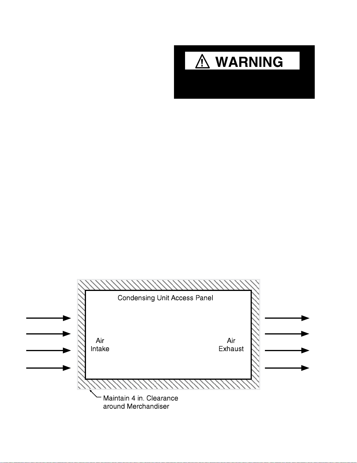
SELF CONTAINED (LOCATION)
SM / SN models have a condensing unit that
draws ambient air through one side of the unit
and discharges hot air out by the opposite side.
In order to maintain refrigeration performance
and compressor life, a minimum space of
4 inches must be maintained between the
merchandiser and surrounding surfaces.
For California Businesses:
This product may contain chemicals known
to the State of California to cause cancer,
birth defects, or other reproductive harm.
This warning is the result of the California State
law known as the California Safe Drinking Water
and Toxic Enforcement Act of 1986, which is
commonly referred to as “Proposition 65.”
This warning does not mean that Hussmann
products will cause cancer or reproductive
harm, or is in violation of any product-safety
standards or requirements. As claried by the
California State government, Proposition 65
can be considered more of a ‘right to know’ law
than a pure product safety law. When used as
designed, Hussmann believes that our products
are not harmful. We provide the Proposition 65
warning to stay in compliance with California
State law. It is your responsibility to provide
accurate Proposition 65 warning labels to your
customers when necessary. For more information
on Proposition 65, please visit the California
State government website.
P/N 2400205_G U.S. & Canada 1-800-922-1919 • Mexico 1-800-890-2900 • www.hussmann.com
Page 9
P/N 2400205_G 1-3
MODEL DESCRIPTION
SN models are designed for low temperature
application and can be used for frozen
food products. These models have glass lids
with coating that maintains the lids free of
condensation.
SM models are open-top merchandisers,
designed for low temperature operation. These
models are designed with
a cold wall refrigeration system. The air
circulation inside the merchandiser is
provided by natural convection.
UNLOADING
Unloading from Trailer:
Use a Lever Bar (also known as a Mule,
Johnson Bar, J-bar, Lever Dolly, or Pry
Lever).
Move the merchandiser as close as possible to
its permanent location and remove all packaging.
Check for damage before discarding packaging.
Remove all separately packed accessories such
as kits and shelves.
EXTERIOR LOADING
Do NOT walk on top of merchandisers or
damage to the merchandisers and serious
personal injury could occur.
merchandisers are not structurally
designed to support external loading
such as the weight of a person. Do not place
heavy objects on the merchandiser.
SHIPPING SKID
Each merchandiser is shipped on a skid to
protect the merchandiser’s base, and to make
positioning the case easier.
Remove the skid by raising one end of the
merchandiser approximately 6 inches. Block
the merchandiser securely, and remove the two
skid bolts from the raised end. Replace the
bolts with (provided) leg levelers. Repeat this
procedure at opposing end. Once the leg levelers
are secured in place, the merchandiser may be
slid off the skid and placed in its final location.
DO NOT TILT MERCHANDISER ON ITS
SIDE OR END WHEN REMOVING SKID.
Improper handling may cause damage to
the merchandiser when unloading. To avoid
damage:
1. Do not drag the merchandiser out of the
trailer. Use a Johnson bar (mule).
2. Use a forklift or dolly to remove the
merchandiser from the trailer.
Do NOT stand or walk on top of
merchandiser. Do not store items or
ammable materials atop the unit.
HUSSMANN CORPORATION • BRIDGETON, MO 63044-2483 U.S.A.
Once the skid is removed, the merchandiser
must be lifted —NOT PUSHED— to reposition.
Check floor where merchandisers are to be set
to see if it is a level area. Determine the highest
part of the floor.
Do NOT remove shipping crate until the
merchandiser is positioned
for installation.
SM / SN Spot Merchandisers
Page 10

1-4 InstallatIon
MERCHANDISER LEVELING
Be sure to position merchandisers
properly. Level the merchandiser by all four
corners. Merchandiser(s) must be installed
level to ensure proper operation of the
refrigeration system.
SERIAL PLATE LOCATION
The serial plate is located on the base, next to
the air intake / discharge air louvers. The serial
plate contains all pertinent refrigeration and
electrical information. The serial plate should
not be removed for any reason.
REFRIGERATION UNIT ACCESS
The access panel on the base of the cabinet
provides access to the condensing unit and
electrical box.
WASTE OUTLET
The waste outlet cap must be installed during
normal operation. This prevents warm air from
migrating back through the drain to the inside
of the merchandiser. Failure to cap the waste
outlet, could result in excessive frosting of the
interior walls.
SEALING MERCHANDISER TO FLOOR
If required by local sanitary codes, or if the
customer desires, merchandisers may be sealed
to the floor using a vinyl cove base trim. The
size needed will depend on how much variation
there is in the floor, from one end of the
merchandiser to the other. Sealing of the lower
front and rear panels on self contained models
may hamper their removal for servicing or
maintenance of the condensing unit.
NOTE: Do not allow trim to cover any intake
or discharge grilles located in the lower front
panel.
— LOCK OUT / TAG OUT —
To avoid serious injury or death from electrical
shock, always disconnect the electrical power
at the main disconnect when servicing or
replacing any electrical component. This
includes, but is not limited to, such items as
doors, lights, fans, heaters, and thermostats.
P/N 2400205_G U.S. & Canada 1-800-922-1919 • Mexico 1-800-890-2900 • www.hussmann.com
Page 11

P/N 2400205_G 1-5
Form HSCW01 Rev. 30MAY12 P/N 0525209_B
Hussmann Self-Contained Refrigerat i on Equip ment Sta rt Up Check List
***Please note that failure to follow this start-up document may void your factory warranty***
Step Startup Activity Check
Locate, read and maintain install/operation manual in a safe place for
1
future reference.
2 Examine unit. Confirm there is NO damage or concealed damage.
3 Level the unit, side to side and front to rear.
4 Remove all shipping brackets/compressor straps/bolts etc.
Unit must be run on a dedicated electrical circuit without the use of
5
an extension cord.
Ensure that the proper electrical requirements for the equipment are
6
supplied.
7 Verify field electrical connections are tight.
Verify all electrical wiring is secured and clear of any sharp edges or
8
hot lines.
9 Verify the condensate drain line is properly trapped and pitched.
10 Verify all required clearances on the sides and back of unit.
11
Advise owner/operator that merchandiser must operate at temperature for 24 hrs prior to loading
Verify there are no air disturbances external to the unit. Heat and air
registers, fans, and doors etc.
with product.
LEGAL DISCLAIMER:
Hussmann shall not be liable for any repair or replacements made without the written consent of Hussmann, or w hen the productis installed or operated in a manner
contrary to the printed instructions covering installation and service which accompanied such product.
HUSSMANN CORPORATION • BRIDGETON, MO 63044-2483 U.S.A.
SM / SN Spot Merchandisers
Page 12

1-6 InstallatIon
NOTES:
P/N 2400205_G U.S. & Canada 1-800-922-1919 • Mexico 1-800-890-2900 • www.hussmann.com
Page 13

P/N 2400205_G 2-1
ELECTRICAL / REFRIGERATION
MERCHANDISER ELECTRICAL DATA
Refer to Appendix A of this manual or the
merchandiser’s serial plate for electrical
information.
FIELD WIRING
Field wiring must be sized for component
amperes stamped on the serial plate. Actual
ampere draw may be less than specified.
ALWAYS CHECK THE SERIAL PLATE FOR
COMPONENT AMPERES
ELECTRICAL CONNECTIONS
SN / SM models have a power cord attached
to the unit with a ground prong. The cord is
rated 115V / 15 Amp.
ELECTRICAL OUTLET:
Before the merchandiser is connected to any
wall circuit, use a voltmeter to check that the
outlet is at 100% of the rated voltage. The wall
circuit must be dedicated for the merchandiser.
Failure to do so voids the warranty. Do not
use an extension cord. Never plug in more
than one merchandiser per electrical circuit.
• Always use a dedicated circuit with the
amperage stated on the unit.
• Plug into an outlet designed for the plug.
• Do not overload the circuit
• Do not use long or thin extension cords.
Never use adapters.
• If in doubt, call an electrician.
All of these models are 60 hz, 1 ph. Connecting
this unit to any electrical supply other than
specified on the serial plate will void the
warranty and may result in serious damage to
the unit. The cabinet should be supplied with
its OWN service.
— LOCK OUT / TAG OUT —
To avoid serious injury or death from electrical
shock, always disconnect the electrical power
at the main disconnect when servicing or
replacing any electrical component. This
includes, but is not limited to, such items as
doors, lights, fans, heaters, and thermostats.
Risk of Electric Shock. If cord or plug
becomes damaged, replace only with
a cord and plug of the same type.
Merchandiser must be grounded.
Do not remove the power supply cord ground.
HUSSMANN CORPORATION • BRIDGETON, MO 63044-2483 U.S.A.
SM / SN Spot Merchandisers
Page 14

2-2 ElE ctri cal / rE frig E rat i on
REFRIGERATION
(Self Contained Models)
Each self contained model is equipped
with its own condensing unit and control
panel located beneath the display area. The
correct type of refrigerant will be stamped
on each merchandiser’s serial plate. The
merchandiser refrigeration piping is leak
tested. The unit is charged with refrigerant,
and shipped from the factory with all service
valves open.
SN / SM models have a refrigeration system
that uses a hermetic compressor. SN / SM
systems use a capillary tube for refrigerant
control. The capillary tube is soldered to
the suction line pull-out coil for proper
heat exchange. If the capillary should become
plugged or damaged, it is best to replace the
heat exchanger.
TEMPERATURE CONTROL
An adjustable thermostat is provided for the
operation of the case. The thermostat on the
SM-110 is located on the right side of the base.
For all other SM / SN models, it is located
on the rear at the left side of the base, next
to the access panel. The thermostat has a
control screw for temperature adjustment. The
compressor will run 100% of the time in the
full clockwise position.
Case
Front
Thermostat
Position only for
SM-110
Case
Back
Access Panel
All other SN/SM
Models
Thermostat
with control
screw
Base
Refrigeration lines are under pressure.
Refrigerant must be recovered before
attempting any connection or repair.
DEFROST
These merchandisers require manual defrost.
When defrosting is necessary, disconnect
electrical power to the merchandiser. Remove
all products. Remove drain plug. Attach a
hose, or use a pan before melting ice begins to
drip out of the drain.
Do not remove frost with a pick, knife or by
scraping with a sharp object. Do not allow
water to drain on the floor. When the unit is
finished defrosting, clean the inside. Install the
plug on the drain tube, and connect the unit to
the correct power supply.
HIGH PRESSURE SWITCH
A high pressure limit switch is provided on all
spot merchandiser models. This switch is used
to limit the discharge pressure of the compressor.
The high pressure switch will automatically
cycle off the compressor and turn on a warning
light on the base, when the discharge pressure in
the system is too high. If this condition occurs,
first clean the condenser. Call for service if the
warning light continues to illuminate.
DOOR INSTALLATION (SN MODELS)
Doors are to be installed after the merchandiser
is placed at its final position. Position the doors
inside of the guides to ensure a good air seal.
P/N 2400205_G U.S. & Canada 1-800-922-1919 • Mexico 1-800-890-2900 • www.hussmann.com
Page 15

P/N 2400205_G 3-1
START UP / OPERATION
START UP
Follow the electromechanical controls start
up procedures as detailed in Section 2 of this
manual.
a. Inspect the refrigeration lines for visible
damage or chafing.
b. Replace access panel.
c. Turn on the electrical power, by plugging
in the merchandiser. The merchandiser
must pull down in temperature. Allow
merchandiser 24 hours to operate before
loading product.
1. The T-stat controller controls refrigeration
temperature. This is factory installed in the
control panel.
HUSSMANN CORPORATION • BRIDGETON, MO 63044-2483 U.S.A.
Defrosts are manual and required when a layer
of ice builds up on the interior walls.
SM / SN Spot Merchandisers
Page 16

3-2 Start up / OperatiOn
LOAD LIMITS
Each merchandiser has a load limit decal. Shelf
life of perishables will be short if load limit is
violated.
LOAD LIMIT
At no time should merchAndisers be
stocked beyond the loAd limits indicAted.
STOCKING
Product should NOT be placed inside the
merchandisers until merchandisers are at
proper operating temperature.
Allow merchandiser 24 hours to operate before
loading product.
Proper rotation of product during stocking is
necessary to prevent product loss. Always
bring the oldest product to the top and set the
newest to the bottom.
THERMOMETER
The cabinet has a “pencil” type thermometer
and reads from -40º F to 120º F / -40º F
to 50º F on 2º increments.
Product will be degraded and may spoil if
allowed to sit in a non-refrigerated area.
P/N 2400205_G U.S. & Canada 1-800-922-1919 • Mexico 1-800-890-2900 • www.hussmann.com
Page 17

P/N 2400205_G 4-1
MAINTENANCE
CARE AND CLEANING
Long life and satisfactory performance of
any equipment is dependent upon the care it
receives. To ensure long life, proper sanitation
and minimum maintenance costs, these
merchandisers should be thoroughly cleaned,
all debris removed and the interiors washed
down, weekly.
Exterior Surfaces
The exterior surfaces must be cleaned with a
mild detergent and warm water to protect and
maintain their attractive finish.
abrasive cleaNsers or scouriNg pads.
Never use
Interior Surfaces
The interior surfaces may be cleaned with most
domestic detergents, ammonia based cleaners
and sanitizing solutions with no harm to the
surface. Self contained models empty into a
limited capacity evaporation pan, which will
overflow if excess water is used in cleaning.
Do:
•Disconnect electrical power before cleaning.
•Remove the product and all loose debris to
avoid clogging the waste outlet.
•Store product in a refrigerated area such as a
cooler. Remove only as much product as can
be taken to the cooler in a timely manner.
•Thoroughly clean all surfaces with soap and
hot water.
pressure hoses to wash the iNterior.
These will desTroy The merchandisers’
sealing causing leaks and poor performance.
do Not use steam or high water
Do NOT allow cleaning agent or
cloth to contact food product.
Do NOT Use:
•Abrasive cleansers and scouring pads, as these
will mar the finish.
•Coarse paper towels on coated glass.
•Ammonia-based cleaners on acrylic parts.
•Solvent, oil or acidic based cleaners on any
interior surfaces.
•Do not use high pressure water hoses.
Product will be degraded and may spoil if
allowed to sit in a non-refrigerated area.
•Do NOT flood merchandiser with water.
Never iNtroduce water faster thaN the
waste outlet caN remove it.
emove draiN cap, aNd collect water
r
duriNg the cleaNiNg process iN a paN. do
Not allow the water to draiN oN the
floor.
•Allow merchandisers to dry before resuming
operation.
•After cleaning is completed, turn on power to
the merchandiser.
HUSSMANN CORPORATION • BRIDGETON, MO 63044-2483 U.S.A.
SM / SN Spot Merchandisers
Page 18

4-2 Maintenance
CAUTION
!
!
GLASS LIDS
The glass lids are made of tempered, non-heated
glass. The lids slide horizontally. The lids are
not self-closing. The lid tracks must be cleaned
periodically to allow the lids to close freely.
Do NOT use HOT water on Cold glass Surfaces.
This can cause the glass to shatter and could
result in personal injury. Allow glass fronts, to
warm before applying hot water.
CLEANING STAINLESS STEEL SURFACES
Use non-abrasive cleaning materials, and
always polish with grain of the steel. Use warm
water or add a mild detergent to the water and
apply with a cloth. Always wipe rails dry after
wetting.
CLEANING PENCIL THERMOMETER
SN / SM models have pencil thermometers.
The thermometer is located at the top, front
center of the merchandiser’s cabinet interior.
To clean the thermometer:
1. Remove the two screws securing the
thermometer to its mounting bracket.
2. Remove the plastic ends from the
thermometer. Then, slide out the glass
tube.
2. Use non-abrasive cleaning materials and a
mild detergent to clean glass tube and
thermometer cover.
3. Replace thermometer.
Use alkaline chlorinated or non-chlorine
containing cleaners such as window cleaners
and mild detergents. Do not use cleaners
containing salts as this may cause pitting and
rusting of the stainless steel finish. Do not use
bleach.
Pencil Thermometer
WARNING
— LOCK OUT / TAG OUT —
To avoid serious injury or death from electrical shock, always disconnect the electrical
power at the main disconnect when servicing
or replacing any electrical component. This
includes, but is not limited to, such items as
doors, lights, fans, heaters, and thermostats.
P/N 2400205_G U.S. & Canada 1-800-922-1919 • Mexico 1-800-890-2900 • www.hussmann.com
Page 19

P/N 2400205_G 4-3
CLEANING COILS
Condenser coils should be cleaned at least once
per month. Additional cleaning may be needed
depending on the operational environment.
Airflow blockage increases energy consumption
and reduces the merchandiser’s ability to maintain operating temperature.
To clean fin coils, use a vacuum cleaner with
a wand attachment and a soft (non-metallic)
brush to remove dirt and debris. Do not bend
coil fins. Always wear gloves and protective eye
wear when cleaning near sharp fins and dust
particles. Unplug merchandiser before servicing.
Fin Coils
NEVER USE SHARP OBJECTS AROUND
COILS. Use a soft brush or vacuum brush to
clean debris from coils. Do not puncture coils!
Do not bend fins. Contact an authorized
service technician if a coil is punctured,
cracked, or otherwise damaged.
ICE in or on the coil indicates the refrigeration
and defrost cycle is not operating properly.
Contact an authorized service technician to
determine the cause of icing, and to make
adjustments as necessary. To maintain product
integrity, move all product to a cooler until
the unit has returned to normal operating
temperatures.
DO NOT FLOOD!
Use only enough water necessary to clean
surface. Water must not drip down the case!
Never use ammonia based cleansers, abrasive
cleansers, or scouring pads.
Always Wear gloves and protective eye wear when
servicing. Turn off evaporation pan heater, and allow
pan to cool.
HUSSMANN CORPORATION • BRIDGETON, MO 63044-2483 U.S.A.
Unplug unit from receptacle
before cleaning or maintenance.
SM / SN Spot Merchandisers
Page 20

4-4 Maintenance
BUMPERS AND OPTIONAL KITS
Most scratches and dings can be removed
using the following procedure.
1. Use steel wool to smooth out the surface
area of the bumper.
2. Clean area.
3. Apply vinyl or car wax and polish surface
for a smooth glossy finish.
3. Make sure proper cleaning procedures are
followed. Lights and fans MUST be turned off
when a case is cleaned and MUST be allowed to
dry before turning power back on.
4. Do not use a pressure nozzle to clean inside
of case.
P/N 2400205_G U.S. & Canada 1-800-922-1919 • Mexico 1-800-890-2900 • www.hussmann.com
Page 21

P/N 2400205_G 4-5
Record starting date
Store Address
Unit Model Number
Unit Serial Number
Contractor/Technician
Check in with store manager, record any complaints or issues
x
Lookunitoverforanydamage, vibrationsorabnormal noise.
x
x
Confirm refrigerant lines properly are secured and not touching
or rubbing other lines, wires or frame work.
x
x
Confirm fan blade/s are tight and not r ubbing or hitting.
x
x
x
x
Check all electrical wiring make sure it is secured and not on
any sharp edges or hot lines.
x
registers,fans, and doors etc.
x
x
base cleaner. Rinse off any cleaner residue.
x
base cleaner. Rinse off any cleaner residue.
x
Clean condenser coil/s and fan blade/s. Do not use an acid base
Cleaner. Rinse off any cleaner residue.
x
Clean condensate drain pan and drain line.
x
x
x
x
Record condenser air inlet temperature
x
x
x
x
x
x
Record defrost heater voltage and am p d r aw.
x
Record anti-sweat heater voltage and amp draw.
x
x
Record unit discharge air temperature.
x
x
x
x
Manual for proper controller operation.
x
x
x
x
Self-Contained Refrigeration EquipmentMaintenance Check List
* * * * * Warranty does not cover issues caused by improper installation or lackofbasic preventative maintenance. * * * * *
Store Name and Number
Technician
PMdate
PMactivity-For visual inspection items,denote"okor
complete" in the column to right when PM has been
performed. For measured data requested, record data
requested in the appropriate column to the right)
they have with unit.
Verify unit is level side to side and front to rear.
Verify fan motors and motor mounts are tight.
Make sure all electrical connections, factory and field, are tight.
Verify ele ctric al connections at lamps are they secure and dr y.
Check for and replace any frayed or chaffed wiring.
Check for air disturbances externallto the unit. Heat and air
Check for water leaks.
Clean evaporator coil/s andfan blade/s. Do not use an acid
Clean discharge air honeycombs or grilles. Do not use an acid
Verify condensate drain lines are clear and functioning.
Record voltage reading at unit with unit off?
Verify condenser and evaporator fans are working.
Quarterly
Semi-
Annually
Ql
Q2
Q3 Q4
Ql
Q2
Q3 Q4
Record condenser air outlet temperature
Is condenser air inlet or air exhaust restricted or recirculating?
Verify there are no visual oil or refrigerant leaks.
Record voltage readingwith unit running.
Record compressor amp draw.
Record case product temperature.
Record unit return air temperature.
Record ambient conditions around unit (wet Bulb temperature
and dry bulb temperature).
Check product loading, do not load beyond the units load limits.
Verify clearances on sides/back of unit.
Check unit controller for proper operation. See controller or 1/0
Confirm door switches function.
Verify unit doors and lids work and are sealed correctly.
Verify that all the panels, shields and covers are in place.
Technician Notes:
Form HSCW03 Rev-29 OCTOBER13
HUSSMANN CORPORATION • BRIDGETON, MO 63044-2483 U.S.A.
x
P/N 0525210_C
SM / SN Spot Merchandisers
Page 22

4-6 Maintenance
NOTES:
P/N 2400205_G U.S. & Canada 1-800-922-1919 • Mexico 1-800-890-2900 • www.hussmann.com
Page 23

P/N 2400205_G 5-1
SERVICE
TROUBLESHOOTING GUIDE
PROBLEM
Compressor runs continuously
product too warm
High head pressure
(High pressure switch on)
Warm storage temperature
PROBABLE CAUSE
1. Short of refrigerant
2. Dirty condenser
1. Cabinet location too warm
2. Restricted condenser air
flow
3. Defective condenser fan
motor
4. Air or non-condensable gases
in system
1. Temperature control not
set properly
2. Short of refrigerant
3. Cabinet location too warm
4. Low voltage, compressor
cycling on overload
5. Condenser dirty
SOLUTION
1. Leak check, change drier,
evacuate, and recharge
2. Clean
1. Relocate cabinet
2. Clean condenser to remove air
flow restriction
3. Replace
4. Leak check, change drier,
evacuate and recharge
1. Reset control.
2. Leak check, replace drier
evacuate and recharge
3. Relocate
4. Check power
5. Clean
Compressor runs continuously
product too cold
Compressor will not start no
noise
Compressor will not start
cuts out on overload
1. Adjust to warmer setting
2. Control feeler not in tube
properly
3. Short on refrigerant
1. Power disconnected
2. Defective or broken wiring
3. Defective overload
4. Defective temperature control
5. Blown fuse or breaker
1. Low voltage
2. Defective relay
3. Restriction or moisture
4. Inadequate air condenser
5. Defective condenser fan
motor
1. Replace
2. Assure proper length in
tube
3. Leak check change drier,
evacuate and recharge
1. Check service cords or
wiring connections
2. Repair or replace
3. Replace
4. Replace
5. Replace fuse or reset
breaker
1. Contact electrician
2. Replace
3. Leak check, replace drier,
evacuate and recharge
4. Clean condenser
5. Replace
HUSSMANN CORPORATION • BRIDGETON, MO 63044-2483 U.S.A.
SM / SN Spot Merchandisers
Page 24

5-2 Service
Parts List
Models SN‐090W SN‐115W SN‐190W SM‐115W SM‐110W
Standard Parts
Descripon Part Number
Thermometer 1700559 X X X
Caster w/ Break 1400516 X X X X
Caster w/ Break 1400524
Power Cord/Main Harness NEMA 5‐15P 1800619 X X X X X
Refrigeraon Thermostat 1700528 X X X X X
High Pressure Indicang Light 1800629 X X X X X
High Pressure Control 1700549 X X X X X
Models SN‐090W SN‐115W SN‐190W SM‐115W SM‐110W
Refrigeraon
Descripon Part Number
Condenser Fan Motor 1800618 X X X X X
Condenser Fan Blade 1700156 X X X X X
Drier (C052‐S) 1700481 X X X X X
Cap Tube Assembly 7600589 X
Cap Tube Assembly 7600524
Cap Tube Assembly 7600543
Cap Tube Assembly 7600577
Compressor‐ Hermec (1/4) AE2410Z‐AA1A 0546974 X X
Compressor‐ Hermec (1/3) 127/60AEA2411ZXA 2000522
Condenser 2100516 X X
Condenser 2100539
X
X
X
X
X X
X
X
X
X
X
Models SN‐090W SN‐115W SN‐190W SM‐115W SM‐110W
Sheel Metal Replacement Parts Painted
Descripon Part Number
Access Panel ‐Black 0201554
Base Cover‐ Black 0201565 X
Base Cover‐ Black 0201566
Base Cover‐ Black 0200969
X
X
X
X
Models SN‐090W SN‐115W SN‐190W SM‐115W SM‐110W
Replacement Lids
Descripon Part Number
Upper Lid 7100632 X
Lower Lid 7100633 X
Upper Lid 7100634
Lower Lid 7100635
Upper Lid 7100538
Lower Lid 7100539
X
X
X
X
P/N 2400205_G U.S. & Canada 1-800-922-1919 • Mexico 1-800-890-2900 • www.hussmann.com
Page 25

Appendix A — TechnicAl dATA A-1
SM / SN
Dimensions shown as inches and (mm).
— LOCK OUT / TAG OUT —
To avoid serious injury or death from electrical shock, always disconnect the electrical
power at the main disconnect when servicing
or replacing any electrical component. This
includes, but is not limited to, such items as
doors, lights, fans, heaters, and thermostats.
Product will be degraded and may spoil if
allowed to sit in a non-refrigerated area.
HUSSMANN CORPORATION • BRIDGETON, MO 63044-2483 U.S.A.
SM / SN Spot Merchandisers
Page 26

A-2 Appendix A —TechnicAl dATA
REFRIGERATION DATA
Models: SN-090, SN-115, SN-190
SM-115, SM-110
Thermostat
Setting CI/CO (°F)
All Models + 0.5º F / -8.5º F
Compressor (hp)
1
SM-115, SN-115, SN-090
SM-110, SN-190
/4 hp
1
/3 hp
Condensing Unit Capacity
SM-115, SN-115, SN-090 800
SM-110, SN-190 1238
(at -30º F evaporation and 100º F
condensing temperature)
DEFROST DATA
Frequency: Manual Defrost
(as needed)
PHYSICAL DATA
Refrigerant Charge
SM-110 15 oz 0.425 kg
SM-115 15.5 oz 1.439 kg
SN-090 14 oz 0.397 kg
SN-115 15.5 oz 0.439 kg
SN-190 17 oz 0.482 kg
Note: This data is based on store temperature
and humidity that does not exceed 75°F and
55% R.H. unless otherwise stated.
P/N 2400205_G U.S. & Canada 1-800-922-1919 • Mexico 1-800-890-2900 • www.hussmann.com
Page 27

Appendix A — TechnicAl dATA A-3
Electrical Data
Note: These are rated values for individual components and should not be added together to
determine total merchandiser electrical load.
Condensing Unit (115V, 1Ph, 60Hz) Standard
SM-115 / SN-115 / SN-090 SM-110 / SN-190
Compressor LRA 30.2 40
Compressor RLA 4.5 6.5
Product Data
3
SM-110 Interior Volume (Cu Ft/Case) 12 ft
SM-115 Interior Volume (Cu Ft/Case) 8.83 ft
SN-090 Interior Volume (Cu Ft/Case) 6.73 ft
/case (338.80 liters /case)
3
/case (250.03 liters /case)
3
/case (190.57 liters /case)
3
SN-115 Interior Volume (Cu Ft/Case) 8.83 ft
SN-190 Interior Volume (Cu Ft/Case) 15.40 ft
ESTIMATED SHIPPING WEIGHT
/case (250.03 liters /case)
3
/case (436.07 liters /case)
1
Case
SM-110 SM-115
lb (kg) 162 ( 73 ) 178 ( 81 )
SN-090 SN-115 SN-190
167 ( 76 ) 190 ( 86 ) 300 ( 136 )
1
Actual weights will vary according to optional kits included
HUSSMANN CORPORATION • BRIDGETON, MO 63044-2483 U.S.A.
SM / SN Spot Merchandisers
Page 28

A-4 Appendix A — TechnicAl dATA
SN / SM
ELECTRIC SPECIFICATIONS
SN/SM - 075/090/115/140/190
SM-110
VOLTS 115V
FRECUENCY 60HZ
BK
START
CAPACITOR
WARNING
DISCONNECT THE CASE FROM THE
ELECTRICAL POWER SUPPLY TO AVOID
RISK OF ANY ELECTRICAL SHOCK.
ADVERTENCIA
ANTES DE HACER CUALQUIER REPARACION
DESCONECTE EL APARATO DE LA TOMA DE
CORRIENTE PARA EVITAR ACCIDENTES
R
THERMOSTAT
R
2
1
3
PRESSURE
CONTROL
BK
THERMIC
PROTECTOR
PRESSURE
LIGHT
BK
NEMA
5-15P
BK
W
115 V
60HZ
1HP
C
RELAY
W
BK
TS
CONDENSER
FAN MOTOR
BK
GRN
2400589_F
P/N 2400205_G U.S. & Canada 1-800-922-1919 • Mexico 1-800-890-2900 • www.hussmann.com
Page 29

To obtain warranty information
or other support, contact your
Hussmann representative.
Please include the model and
serial number of the product.
Hussmann Corporation, Corporate Headquarters: Bridgeton, Missouri, U.S.A. 63044-2483 01 October 2012
Page 30

Hussmann Corporation,
12999 St. Charles Rock Road
Bridgeton, MO 63044-2483
www.hussmann.com
 Loading...