

Page 1
P/N0492433D
®
SI3E
Technical Data Sheet
P/N 0492433_D
NSF
®
Certified
April 2010
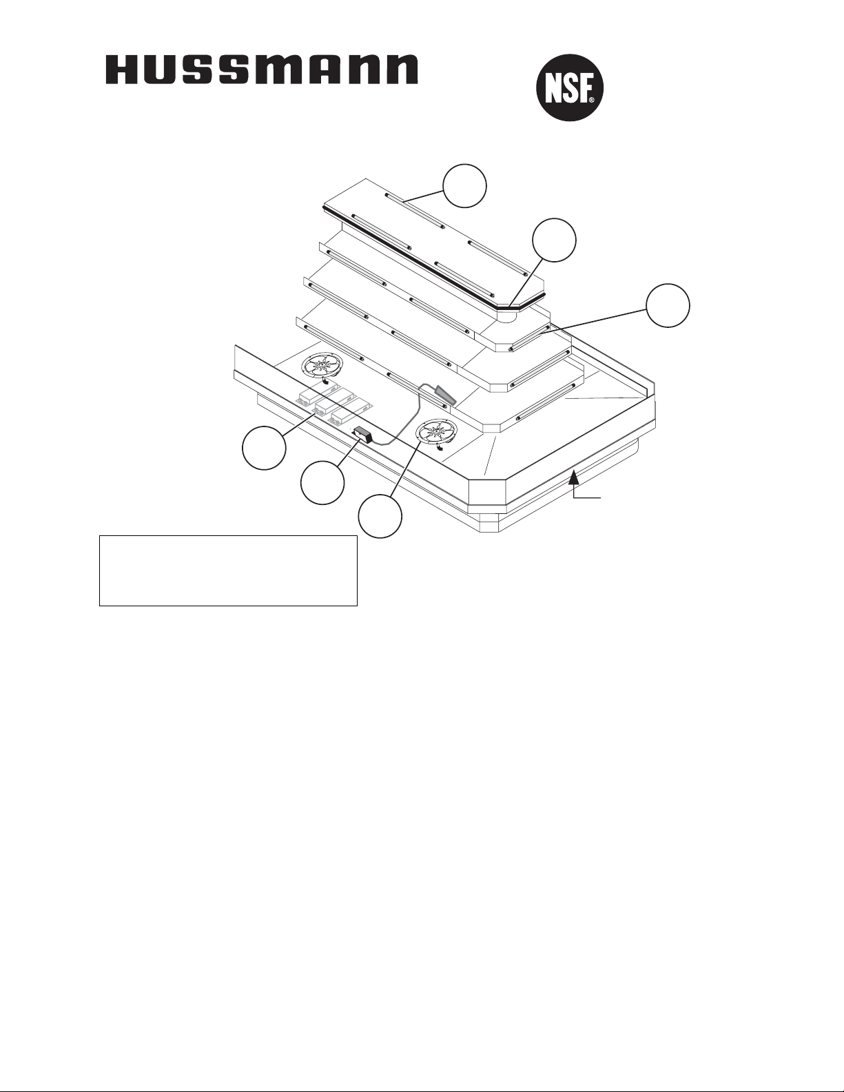
Item Part # Description Wiring Item #
F
AN ASSEMBLIES AND THERMOSTATS
8 Ft & 10 Ft
A. 12W Standard Fan Assembly (1)
0047000 Fan Motor, Evaporator
(MO.4410103)
0407532 Fan Blade (FB.4780619)
embossing toward motor
10 Ft
A. 12W Energy Efficient Fan Assembly (1)
0477655 Fan Motor, Evaporator
(MO.4410546)
0407532 Fan Blade (FB.4780619)
embossing toward motor
B. Optional Adjustable Refrigeration Thermostat (2)
0448347 (CT.4481631)
Item Part # Description Wiring Item #
HEATERS
C. Anti-Sweat Heater (3)
0487122 8 ft (HE.4851033)
0487123 8 ft (HE.4851034)
0487124 10 ft (HE.4851035)
0487125 10 ft (HE.4851036)
L
AMPS AND BALLASTS
D. Ballast, Electronic (4)
0355398 3 Lamps (BA.4480118)
0355716 2 Lamps (BA.0355716)
0447739 (BA.4480900)
E. Fluorescent Lamp (5)
Replace with like fixtures
©2010 HUSSMANN CORPORATION • BRIDGETON, MO 63044-2483 U.S.A.
U.S. & CANADA 1-800-922-1919 • MEXICO 1-800-522-1900 • WWW.HUSSMANN.COM
We reserve the right to change or revise specifications
and product design in connection with any feature of
our products. Such changes do not entitle the buyer to
corresponding changes, improvements, additions or
replacements for equipment previously sold or shipped.
Note: Revision D adds energy efficient fan Btu note on page 3.
D
B
A
E
C
E
Serial Plate
Page 2
8 ft 10 ft
General
(A) Overall Case Length 96 (2438) 120 (3048)
(B) Base Length 76 3/
4 (1950) 110
1
/
2 (2807)
Maximum O/S dimension of case back to front (includes bumper) 72 (1829) 72 (1829)
Front of splashguard to O/S edge of front base rail 1
5
/8 (41) 1 5/8 (41)
Front of case to O/S edge of front base rail 13 1/
8 (333) 13
1
/
8 (333)
Back of case to O/S edge of front base rail 58
7
/8 (1495) 58 7/8 (1495)
Width of base rail 1 7/8 (48) 1 7/8 (48)
(D) Length of Canopy 69 1/8 (1756) 93 1/8 (2365)
Width of Canopy 18 1/8 (460) 18 1/8 (460)
Electrical Service (Electrical Field Wiring connection point)
Center of Electrical service to O/S edge of front base rail 47 (1194) 47 (1194)
Left end of case to center of field connection box 27 (686) 27 (686)
right end of case to center of field connection box 69 (1753) 93 (2362)
Waste Outlets
(C) LH End of case to the center of waste outlet 81 (2057) 96 (2438)
Center of front waste outlet to outside of front base rail 8 7/8 (225) 8 7/8 (225)
Center of back waste outlet to outside of front base rail 40 1/8 (1019) 40 1/8 (1019)
Schedule 40 PVC drip pipe 1 1/2 (38) 1 1/2 (38)
Refrigeration Outlet
LH end of case to center of refrigeration outlet 22 (559) 22 (559)
RH end of case to center of refrigeration outlet 74 (1880) 98 (2489)
2 of 7
SI3E Technical Data Sheet
U.S. & CANADA 1-800-922-1919 • MEXICO 1-800-522-1900
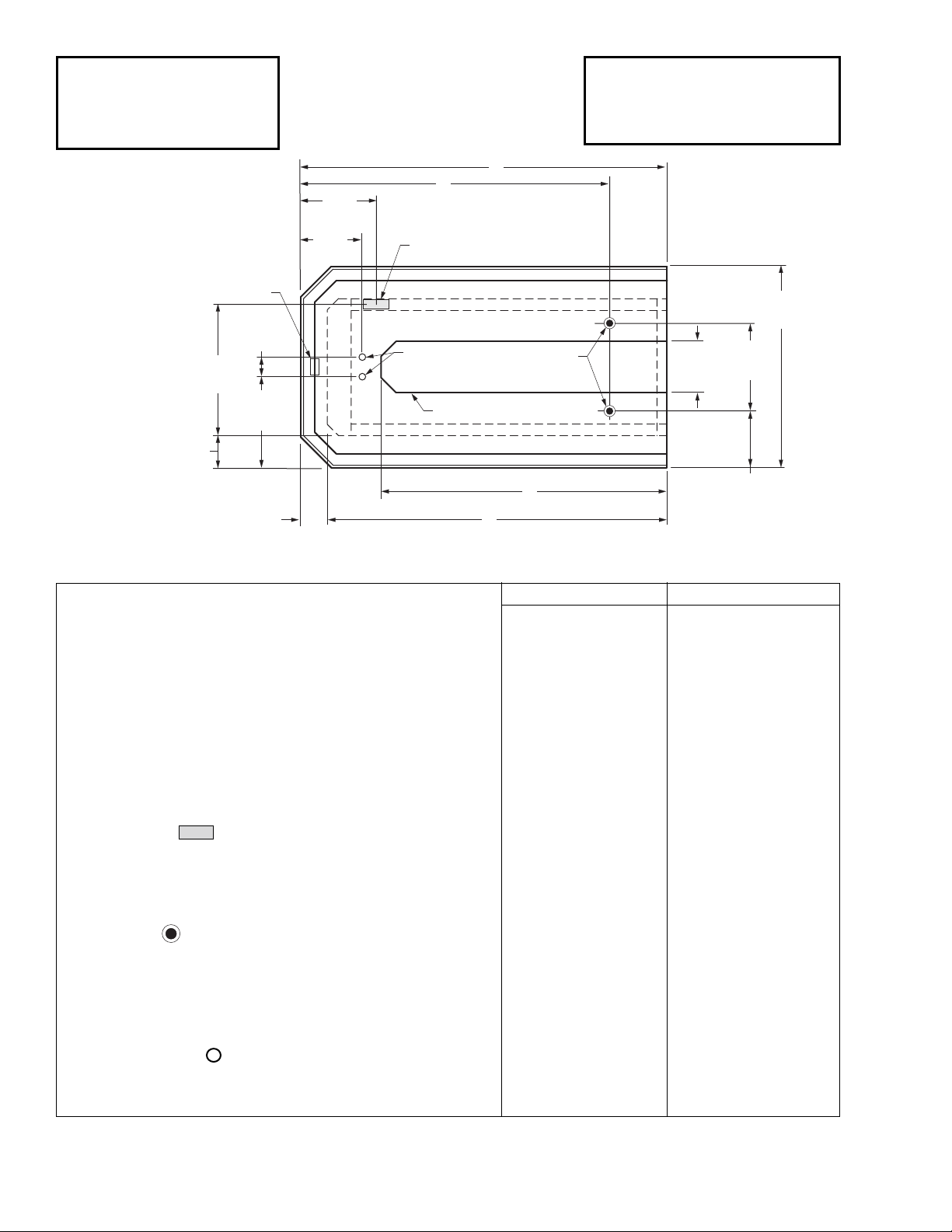
Engineering
Plan Views
Front
08-2009
SI3E Island
PHYSICAL DATA
Merchandiser Drip Pipe (in.) 1 1/2
Merchandiser Liquid Line (in.)
3
/8
Merchandiser Suction Line (in.)
5
/8
Dimensions shown as inches and (mm).
C
A
27
Serial
Plate
(686)
22
(559)
Field Connection
Electrical Box
72
(1829)
31 1/4
(794)
47
(1194)
7
(178)
32 1/2
(826)
Refrigeration
Outlets
Canopy
Waste
Outlets
18 1/8
(460)
1 1/2
(292)
D
9 1/2
(241)
B
20 3/8
(518)
Page 3
3 of 7P/N 0492433_D
HUSSMANN CORPORATION • BRIDGETON, MO 63044-2483 U.S.A. • WWW.HUSSMANN.COM
Dimensions shown as inches and (mm).
REFRIGERATION DATA
Note: This data is based on store tempera-
ture and humidity that does not exceed
75°F and 55% R.H.
SI3E
Discharge Air (°F) 27
Evaporator (°F) 20
Unit Sizing (°F) 18
Btu/hr/ft
‡
L
IT & UNLIT SHELVES SI3E
Parallel 1820
Conventional 1985
‡
Optional energy efficient motors reduce the
refrigeration load by 109 Btu/hr/ft.
DEFROST DATA
SI3E
Frequency (hr) 4
Defrost Water (lb/ft/day) 12
(± 15% based on case configuration and
product loading).
OFFTIME SI3E
Time Terminated (minutes) 20
ELECTRIC OR GAS Not Recommended
CONVENTIONAL CONTROLS
Low Pressure Backup Control
SI3E
CI/CO* 14°F / 4°F
Indoor Unit Only, Pressure Defrost
Termination* 48°F
*Use a Temperature Pressure Chart to determine PSIG conversions.
Estimated Charge ** SI3E
8 ft 1.7 lb 27 oz 0.8 kg
10 ft 2.1 lb 34 oz 1.0 kg
**This is an average for all refrigerant types.
Actual refrigerant charge may vary by approximately half a pound.
SI3E
Delicatessen
NSF®Certification
This merchandiser is manufactured to meet ANSI/NSF
®
(National Sanitation
Foundation) Standard #7 requirements for construction, materials & cleanability.
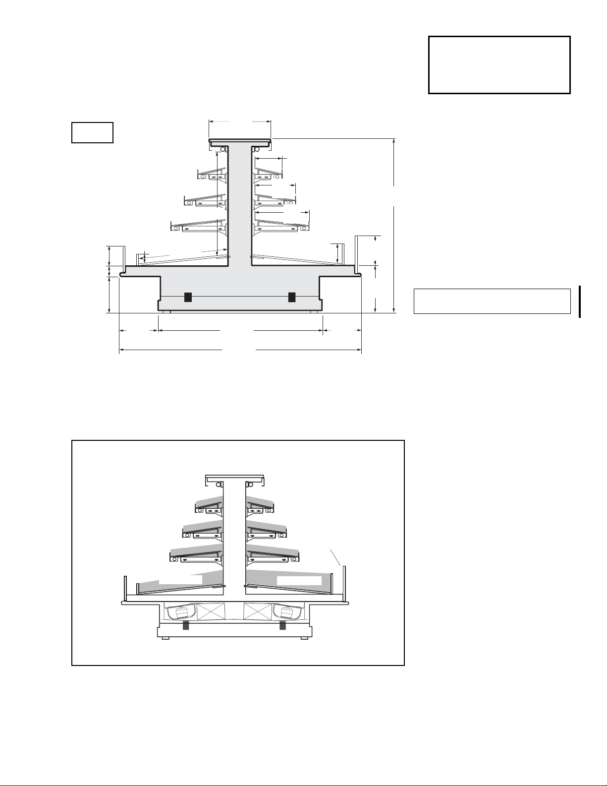
Multi-deck Island End, 4 Display Levels
SI3E
Load Limit Profile
Air flow between the shelves, from the Center Air Discharge (CAD) to the return, must be
maintained at all times for optimum operating efficiency and to prolong product shelf life.
At no time should merchandisers be stocked beyond the load limits indicated.
Cases may not function properly if they are loaded above load limits.
18 1/8
(460)
30 3/4 (781)
Standard Height Plex
and Product Stop
3 (76)
5 7/8 (149)
27
(686)
3 1/4 (83)
10 7/8
(276)
12
(305)
(203)
16
(406)
8
6 (152)
Optional High Plex
and Product Stop
8 7/8
(225)
14 1/8
(359)
51 3/4
(1315)
11 1/2
(292)
49 (1245)
11 1/2
(292)
72 (1829)
CAD
Load Limit
Optional Shelves
Optional High Plex
with 6 in. (152 mm)
Product Depth
Load Limit
SI3E
Page 4

4 of 7
SI3E Technical Data Sheet
U.S. & CANADA 1-800-922-1919 • MEXICO 1-800-522-1900
SI3E
Delicatessen
Electrical Data
8 ft 10 ft
Number of Fans – 12W 8 10
Amperes Watts
8 ft 10 ft 8 ft 10 ft
Evaporator Fan
120V 60Hz Standard 5.20 6.50 400 500
120V 50Hz Standard 6.00 7.50 456 570
230V 60Hz Export NA NA NA NA
230V 50Hz Export NA NA NA NA
120V 60Hz Energy Efficient 2.40 3.00 144 180
230V 60Hz Energy Efficient NA NA NA NA
Anti-sweat Heaters †
120V 60Hz Standard 0.70 0.70 84 84
230V 50Hz Export NA NA NA NA
Minimum Circuit Ampacity (MCA)
†
120V 60Hz Standard 6.57 7.87
120V 50Hz Standard 6.81 8.31
230V 60Hz Export NA NA
230V 50Hz Export NA NA
120V 60Hz Energy Efficient 3.21 3.81
230V 60Hz Energy Efficient NA NA
Maximum Over Current Protection 120V 20 20
Maximum Over Current Protection 230V NA NA
Standard Lighting
1 Row Canopy 0.70 0.95 84 114
Optional Lighting
1 Row of Ledge 1.33 1.67 160 200
Shelf Lighting
1 Row of Shelves 0.84 1.09 100 130
2 Rows of Shelves 1.68 2.18 200 260
3 Rows of Shelves 2.51 3.26 301 391
115V Lighting Circuit Total = Standard Lighting + Total Optional Lighting + Optional Shelf Lighting
does not
Page 5

5 of 7P/N 0492433_D
HUSSMANN CORPORATION • BRIDGETON, MO 63044-2483 U.S.A. • WWW.HUSSMANN.COM
ESTIMATED SHIPPING WEIGHT
4
Case
8 ft 10 ft End
lb (kg) 1200 (544) 1400 (635) NA
4
Actual weights will vary according to optional kits included.
Product Data
SI3E8
Recommended Usable Cube 1 (Cu Ft/Case) 54.31 ft3 /case (1.54 m3/case)
AHRI Total Display Area 2 (Sq Ft/Case) 51.86 ft2 /case (4.82 m2 /case)
Shelf Area 3(Sq Ft/Case) 85.76 ft2 /case (7.97 m2 /case)
SI3E10
Recommended Usable Cube 1 (Cu Ft/Case) 67.89 ft3 /case (1.92 m3/case)
AHRI Total Display Area 2 (Sq Ft/Case) 64.83 ft2 /case (6.02 m2 /case)
Shelf Area 3(Sq Ft/Case) 107.20 ft2 /case (9.96 m2 /case)
1
AHRI Refrigerated Volume less shelving and other unusable space: Refrigerated Volume / Unit of Length, ft3/ft [m3/m]
2
Computed using AHRI 1200 standard methodology: Total Display Area, ft2[m2] / Unit of Length, ft [m]
3
Shelf surface area is composed of bottom deck plus standard shelf complement, as shown in the Hussmann Product
Reference Guide. The standard shelf complement for this model is (1) row of 8-inch shelf, (1) row of 12-inch shelf, (1) row
of 16-inch shelf.
SI3E
Delicatessen
Page 6

6 of 7
SI3E Technical Data Sheet
U.S. & CANADA 1-800-922-1919 • MEXICO 1-800-522-1900
Fan Wiring
Offtime Defrost
8 & 10 Fans
8 ft
10 ft
120V NEUTRAL
120V POWER
BROWN BAND
BROWN BAND
1
1
Refrigeration Thermostat
2
Light Blue
To
Condensing
}
Unit
Fans
Anti-sweat Heaters
BROWN BAND
BROWN BAND
3
WARNING
All components must have mechanical ground, and the merchandiser must be grounded.
CIRCLED NUMBERS = PARTS LIST ITEM NUMBERS
R = Red Y = Yellow G = Green BL = Blue B = Black W = White
= 120VPOWER
= 120V NEUTRAL = FIELD GROUND
= CASE GROUND
Page 7

7 of 7P/N 0492433_D
HUSSMANN CORPORATION • BRIDGETON, MO 63044-2483 U.S.A. • WWW.HUSSMANN.COM
ORANGE OR TAN BAND
Light Circuits
120V
N
EUTRAL
120V
P
OWER
Light
Switch
G
Lighted Shelf Wiring
W
B
G
B
4
BL
G G G
W
4
BL
G G G
W
G
B
4
BL
G G G
BL
R
5
R
5
R
5
BL BLR R
BL
BL BLR RR
BL
BL BLR RR
BL
R
5
BL
5
BL
5
5
5
5
Typical Shelf Ballast Wiring
Maximum lamps per ballast is three (3).
Different shelf configurations and different
case lengths will have more shelf ballasts.
Optional Ledge Light Circuit
G
W
B
All components must have mechanical ground, and the merchandiser must be grounded.
CIRCLED NUMBERS = PARTS LIST ITEM NUMBERS
R = Red Y = Yellow G = Green BL = Blue B = Black W = White
= 120VPOWER
= 120V NEUTRAL = FIELD GROUND
4
G
WARNING
BL
R
BL
5
BL BLR R R
G G
BL
5
5
= CASE GROUND
 Loading...