

Page 1

1
USER INSTRUCTIONS
Your refrigerated case uses a Hussmann Safe-NETTMIII temperature and
defrost controller to precisely maintain the temperature and prevent frost
buildup on the cooling coil. LEDs indicate when the compressor or
refrigeration is on, when the case is in a defrost cycle, if the temperature is
outside the desired range, or if there is a sensor failure. An adjustment knob
allows the temperature to be set within the configured range and can power
off the controller and compressor.Your controller has been custom-configured
to provide the best temperature and defrost control for your chilled or frozen
food.
The front of the controller has an adjustment knob and status LEDs. The back
of the controller has connections for sensors and switched equipment.
Temperature and
Defrost Controller
Page 2

2
The Safe-NET III controller includes the following features and connections.
• Adjustment knob:
Adjusts the temperature setpoint.
May include an Off Position to turn off the controller, refrigeration, and
defrost heat and fan.
See Your Case Configuration on page 7.
WARNING: The optional evaporator fan remains ON when the
adjustment knob is in the Off position.
• Controller LEDs:
Compressor Powered On LED (green):
Lights while the compressor is running or the refrigeration valve
is open.
Defrost Cycle LED (yellow):
Lights while the refrigeration coil is defrosting.
Temperature or Sensor Alarm (red):
Lights if the temperature is too warm or too cold.
Flashes if a sensor fails.
See Alarms and Codes on page 7.
• Rear connections:
– Case temperature sensor:
Typically senses the temperature of the air in the case.
Used by the controller to determine when to power on or power off
the compressor or refrigeration.
– Evaporator temperature sensor:
Senses the temperature of the refrigeration coil.
Terminates a defrost cycle when refrigeration coil ice melts.
– Compressor or refrigeration relay:
Switches on the compressor or refrigeration valve for cooling.
– Defrost relay:
The Safe-NET III controller includes a defrost relay that switches on
the optional evaporator fan during normal operation and switches on
the defrost heater during a defrost cycle.
Page 3

3
Display
The display includes three red LEDs and two digits for temperature, defrost
status, and error codes.
The three display LEDs are red, and their behavior matches the LEDs on the
controller.
Startup
1. Plug in the case.
WARNING: The Off Position does not disconnect line voltage to the case,
refrigeration unit, fan, or heater.
2. Wait for the self check to complete. During the self check, each LED
flashes for one second, then all LEDs turn on for two seconds. If the
LEDs do not flash, make sure the adjustment knob is not in the Off
position. (See Your Case Configuration on page 7 for Off position
functionality.)
• After the self check, all LEDs turn off until the compressor starts.
There may be a delay before the compressor starts.
If the red Temperature or Sensor Alarm LED stays on after the self
check, see Alarms and Codes on page 4.
• The green Compressor Powered On LED turns on when the
compressor starts.
Temperature Adjustment
Rotate the adjustment knob counter clockwise for a warmer setpoint or
clockwise for a colder setpoint.
• While you are adjusting the temperature, the optional display shows the
setpoint (cut out value). A few seconds after you set the temperature, it
reverts to showing the sensed temperature in the case.
Page 4
4
Alarms and Codes
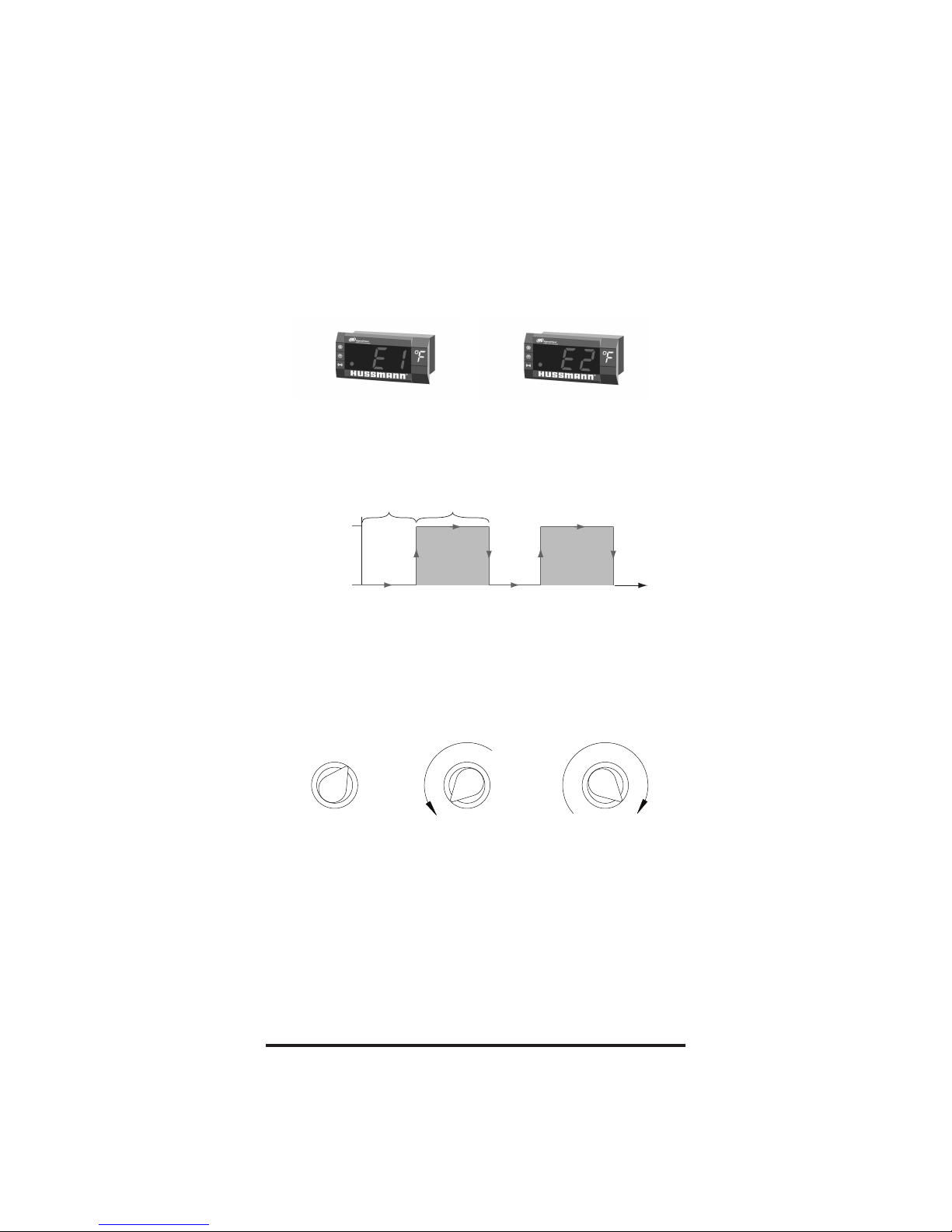
Flashing Temperature or Sensor Alarm LED, E1 or E2
If the Temperature or Sensor Alarm LED (red) on the controller and display is
flashing, a temperature sensor has failed. The display shows E1 if the case
sensor has failed or E2 if the evaporator sensor has failed. (See Alarms and
Codes on page 7.)
If the case sensor fails, depending on the configuration of your controller,
refrigeration will run continuously, turn off, or repeat a duty cycle of a few
minutes on and a few minutes off. The graph below shows an example of duty
cycle operation during a case sensor failure.
Defrost Termination Switch
Your case may use a defrost termination switch, instead of an evaporator
sensor, to terminate a defrost cycle. The defrost termination switch is
temperature activated and senses the completion of defrost. Your Case
Configuration on page 7 shows whether your case includes a defrost
termination switch.
Manual Defrost
Note: The above procedure initiates a manual or forced defrost.
The control has protective settings to prevent short cycling of the compressor.
A. The compressor may run for as long as 1 minute after step 2 is
completed. Start the 10 second count down, for step 3, once the display
is blank.
1
2
3
4
5
6
7
I
I
Warm
Cold
1
2
3
4
5
6
7
I
I
Warm
Cold
1
2
3
4
5
6
7
I
I
Warm
Cold
1. Note location of knob
setting.
2. Rotate knob fully
counterclockwise until
it stops (full warm –
“OFF” position).
3. After 10 seconds, but
before 30 seconds,
rotate knob fully
clockwise until it stops
(full cold position).
On
Status
Off
Compressor
Off Time If
sensor Failed
Compressor or
Refrigeration
Off
Compressor
On Time If
sensor Failed
On
Off
On
Time
Page 5

5
B. The defrost initiation may be delayed for as long as 2 minutes after step
3 is completed.
The display will show “dF” once step 3 is completed, even with the protective
delay timing out. The “dF” will display for a while after defrost has terminated,
to allow the temperature to stabilize.
CAUTION: Return the control knob to its original setting (Step 1) once
the manual defrost has been initiated.
Evaporator Fan Delay
On low temperature models, an evaporator fan delay is incorporated to delay
the fan operation until the evaporator is below its setpoint temperature,
following a defrost cycle.
On some low temperature models, the evaporator fan is briefly cycled to
dissipate the presence of vapor during the defrost cycle.
Service Procedures (for service personnel only
)
Installing a configuration file into a controller from a copy card
The copy card allows service personnel to update the configuration of
a controller.
CAUTION: This procedure must be followed exactly or the controller
may be damaged.
1. Disconnect power to the case (the controller must be powered off).
*2. Connect the copy card to the controller.
3. Make sure the adjustment knob is not in the Off position.
4. To start the installation, reconnect power to the case (the controller
should be powered on).
a. During the file transfer, both LEDs on the copy card turn on.
b. When the data transfer has completed, the green LED remains on
and the red LED turns off.
c. If the red LED remains on and the green LED is off, the transfer failed.
d. If the transfer fails, repeat step 1 through step 4. If it fails again, use
a different copy card or controller.
5. Disconnect power to the case (the controller is powered off).
6. Disconnect the copy card from the controller.
7. Reconnect power to the case (the controller is powered on).
Note: The above procedure can be easily performed through the display
Page 6

6
interface cable, using the addition of a jumper to adapt the connection
to the copy card.
* At Step 2 above:
Disconnect the cable from the rear of the display module and attach it
to the copy card using the jumper. Proceed with Step 3 through Step 7.
Wiring Examples
WARNING: Before wiring the controller, make sure that the
refrigeration unit, fan, heater, and controller are not
connected to the electrical supply. Do not apply voltage to
the digital input.
Evaporator Temperature Sensor P2
Safe-NET III Controller
Digital Input D.I.
Common
Control Sensor Pb1
Line 1
Line 2
Compressor
Phase
Fan
Phase
Heater
Interface box and
copy card TTL connector
Defrost Termination
Switch (NO) (optional)
Optional Evaporator Sensor
Control Sensor (Air Space)
90-240Vac
Line Supply
Compressor
Defrost Heater (optional)
AC Line Supply
AC Line Supply
Defrost Fan (optional)
AC Line Supply
Page 7

7
Your Case Configuration
Alarms and Codes
Alarm or Code Indicates Action
Red LED remains
on after startup.
Firmware corruption on
controller.
Controller is not operating.
Call service immediately.
Red LED turns on
during operation.
Case temperature is too
warm or too cool.
Make sure the door is closed.
Make sure that cold air is not being
blocked or deflected.
Make sure that the evaporator coil
is not iced up.
Check the temperature using the
optional display or a thermometer.
If the LED does not turn off after
one hour call service.
Red LED flashes.
Temperature sensor failure.
E1 indicates a case
temperature failure.
E2 indicates an evaporator
temperature sensor failure.
Check the optional display for error
code E1 or E2 and call service
immediately.
Factory Setting
Average product temperature -10˚F.
Knob position #5
Adjustment knob has Off position. Yes
Delay before compressor runs after startup. Delay Time 30 sec.
Compressor operation if case sensor fails. Compressor On
What the display shows during defrost? dF
The case defrosts when the power is turned
on.
Yes
The method used to end defrost. Evaporator Sensor Temperature
Defrost terminated by termination switch No
Page 8

8
Hussmann Corporation
Ingersoll Rand Climate Control Technologies
12999 St. Charles Rock Road
Bridgeton, MO 63044
www.hussmann.com
©2009 Invensys Controls. All Rights Reserved.
 Loading...