

Page 1

HUSSMANN CORPORATION, Bridgeton, MO 63044-2483 U.S.A.
E
C
B
A
D
P/N 0387185E
Item Part # Description Wiring Item #
F
AN ASSEMBLIES, AND THERMOSTATS
A. Fan Assembly (1)
0047000 Standard motor, 9W
0315470 Fan Blade, 34º pitch
0439053 Optional Energy Efficient Motor
B. Optional Adjustable (2)
Refrigeration Thermostat
C
ONTROL (RMF ONLY)
C. Fan Control (RMF) (3)
0125275 Fan Speed Control, 120V, 60hz
Item Part # (Qty) Description Wiring Item #
L
AMPS AND BALLASTS
J. One-Lamp Ballast
Two-Lamp Ballast
Export Ballast
K. Fluorescent Lamp,
Standard 40W
Refer to door manufacturer’s manual for replacement
door parts.
®
NOTE: Changed items have been underlined.
RM with Anthony Doors
Data Sheet Set
P/N 0387185E
NSF
®
Certified
January, 2003
Warning:
Terminal block NOT for
case-to-case
wire connection!
Merchandisers
Page 2
2 of 5
HUSSMANN CORPORATION, Bridgeton, MO 63044-2483 U.S.A.
RM with Anthony Doors Data Sheet Set
Engineering
Dimensions shown as in. & (mm).
2 Dr 3 Dr 4 Dr 5 Dr
General
(A) Case Length
(without ends or partitions) 62 (1575) 92
1
/
2 (2350) 122
7
/
8 (3121) 153
3
/
8 (3896)
Maximum O/S dimension of case back to front 43
3
/
4 (1111) 43
3
/
4 (1111) 43
3
/
4 (1111) 43
3
/
4 (1111)
(Includes bumper)
Back of case to rear of splashguard 39 3/
8 (1000) 39
3
/
8 (1000) 39
3
/
8 (1000) 39
3
/
8 (1000)
Width of Skidrail 4
1
/
2 (114) 4
1
/
2 (114) 4
1
/
2 (114) 4
1
/
2 (114)
Width of Bottom Front Support 6 (152) 6 (152) 6 (152) 6 (152)
Stub-up area between front skidrail and splashguard 6
3
/
8 (1000) 6
3
/
8 (1000) 6
3
/
8 (1000) 6
3
/
8 (1000)
Electrical Service
RH end of case to the center of nearest knockout 4 (102) 4 (102) 4 (102) 4 (102)
(B) RH end of case to the center of LH knockout 58 (1473) 88
1
/2 (2248) 118 7/8 (3019) 149 3/8 (3794)
Back O/S of case to center of knockout 41 5/8 (1057) 41 5/8 (1057) 41 5/8 (1057) 41 5/8 (1057)
* NOTE: Electrical Field Wiring Connection Point is at terminal.
Waste Outlet
(C) Right end of case to center of waste outlet 23 3/4 (603) 54 1/4 (1378) 46 1/4 (1175) 76 5/8 (1946)
Back O/S of case to center of waste outlet 34 5/8 (879) 34 5/8 (879) 34 5/8 (879) 34 5/8 (879)
Water Seal
Edge of water seal to center of waste outlet 11(279) 11(279) 11(279) 11 (279)
Outside diameter of drip piping 1
1
/4 (32) 1 1/4 (32) 1 1/4 (32) 1 1/4 (32)
** NOTE: Field installed water seal outlets,tees, and connectors are shipped with case
Refrigeration Outlet
RH end of case to center of RH refrigeration outlet 5 3/8 (137) 5 3/8 (137) 5 3/8 (137) 5 3/8 (137)
Back O/S of case to center of refrigeration outlet 32(813) 32(813) 32(813) 32 (813)
(D) Outside bottom front supports from end of case 6
3
/4 (170) 6 3/4 (170) 6 3/4 (170) 6 3/4 (170)
Center bottom front support from Centerline 24 (610) 24 (610) 24 (610) 24 (610)
Distance between Center and Outside supports will vary
01-2003
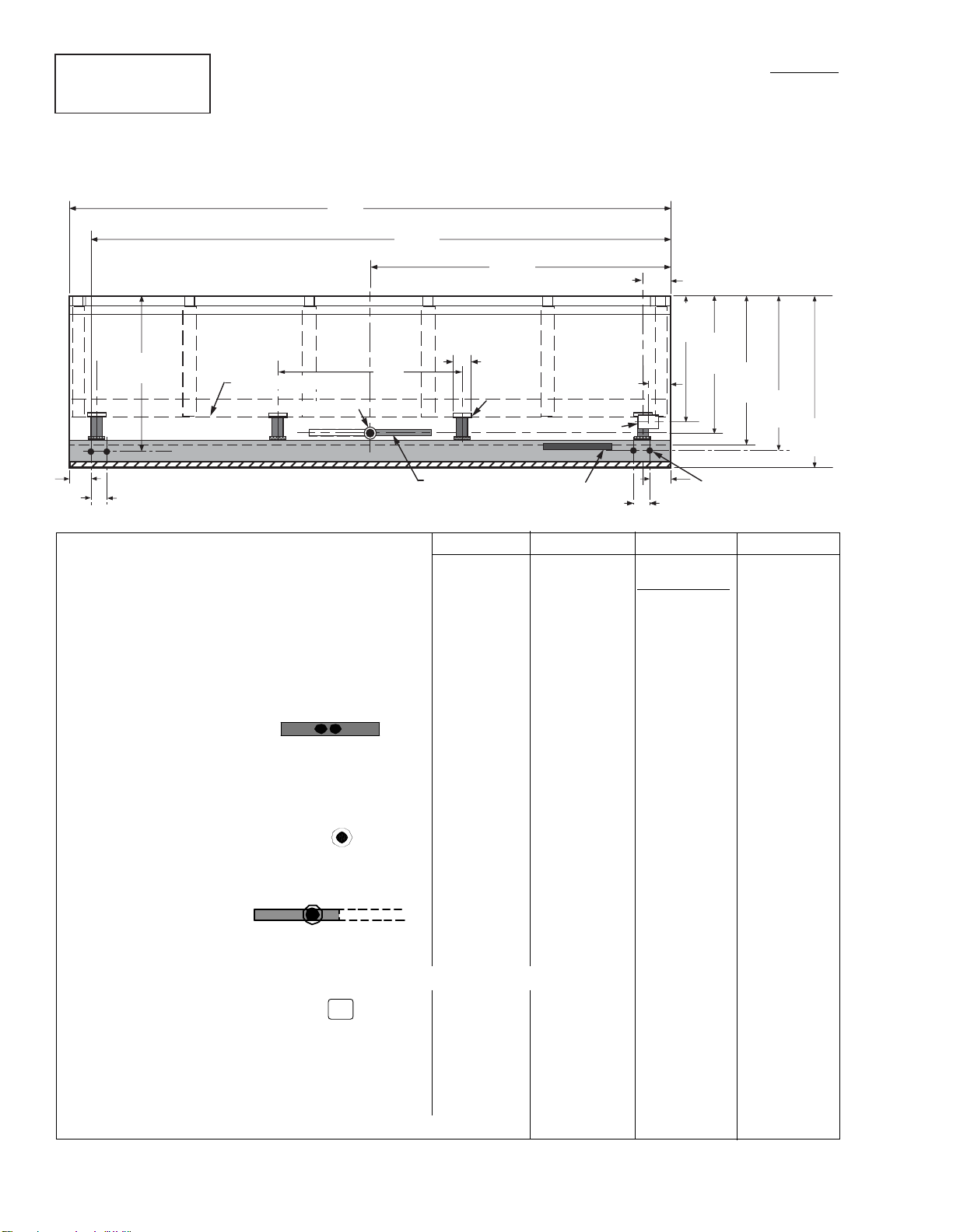
Plan Views
Reach-In
2, 3, 4, & 5 Door
A
RL-RM-RMF
Plan View
B
08-2002
C
D
32
(813)
6
(152)
Water Seal
(see note **)
Bottom Frt.
Support
Refrig. Outlet
Relay & Terminal
Block Location
3
5
(142)
/8
(76)
3
(102)
4
(102)
3
(76)
41
(1056)
9
/16
Skid/External Base
Waste Outlet
Electrical Wireway
48
(1219)
Front
34
(879)
4
(see note *)
5
/8
3
39
/8
(999)
5
41
/8
(1056)
3
43
(1110)
/4
Page 3

HUSSMANN CORPORATION, Bridgeton, MO 63044-2483 U.S.A.
3 of 5
P/N 0387185E
2 5/8
(67)
2 (52)
Fan
Coil
62 1/2
(1588)
1 1/2
(38)
4 3/4
(121)
22 Shelf
(559)
RL/RM/RMF
40 3/4
(1035)
27 5/8 (702)
3
7
/8
(97)
Refrigeration Outlet
Electrical
Field Wiring
Connection
is at Terminal
82
(2083)
34 5/8 (879)
32 (813)
41 5/8 (1056)
39 3/8 (999)
Electrical Stub-up Area
13
(332)
43 3/4 (1110)
67
(1700)
Frame
Dimensions shown as in. & (mm).
NOTE: The bumpers are 4 in. (102 mm) wide. The center of the
bumper is 5
1
/2 in. (140 mm) from the floor.
Reach-in 2, 3, 4 and 5 Door Models
REFRIGERATION DATA
Note: This data is based on store temperature
and humidity levels that do not exceed NSF
guidelines.
MEDIUM TEMP
Discharge Air °F 32
Evaporator °F 27
Unit Sizing °F 24
NSF NSF
BTU/
HR/DOOR* TYPE IT
YPE II
Temp (°F) /R.H. 75°/ 55% 80°/ 55%
Parallel 945 985
Conventional 990 1030
*For all refrigeration equipment other than
Hussmann, use conventional Btu values.
DEFROST DATA
Frequency (hr) 24
Defrost Water (lb/Dr/day) 0.3
(± 15% based on case configuration and
product loading).
ELECTRIC NA
Temp Term (°F) NA
Failsafe (min) NA
G
AS
Not Recommended
OFFTIME 60 min
CONVENTIONAL CONTROLS
Low Pressure Backup Control
CI/CO (Temp °F)** +20°/ +10°
Indoor Unit Only, Pressure Defrost
Termination (Temp °F)**
Not Recommended
**Use a Temperature Pressure Chart to
determine PSIG conversions.
PHYSICAL DATA
Drip Pipe (in.) 1 1/4
Liquid Line (in.)
3
/8
Suction Line (in.)
7
/
8
Estimated Charge (lbs)***
2 Dr 1.8
3 Dr 2.7
4 Dr 3.6
5 Dr 4.6
***This is an average for all refrigerant
types. Actual refrigerant charge may vary by
approximately half a pound.
Length Added to Lineup by each
Standard End (in.) 2
Optional End with Window (in.) 1
1
/2
Optional Partition (in.) 1 1/2
Impact RM
With
Anthony Doors
Dairy, Delicatessen, Beverages
NSF Certification
These merchandisers are manufactured to meet ANSI /National
Sanitation Foundation (NSF
®
) Standard #7 requirements.
Page 4

Impact RM
With Anthony Doors
Dairy, Delicatessen, Beverages
Electrical Data
2Dr 3Dr 4Dr 5Dr
Number of Fans 2345
Amperes Watts
Merchandiser
Fans
Standard 1.40 2.10 2.80 3.50 110 165 220 275
Energy Efficient 0.76 1.14 1.52 1.90 50 75 100 125
(Export: 220V 50 hz) 0.76 1.14 1.52 1.90 108 162 216 270
Constant on Anti-sweat Heaters
Doors (Not Applicable)
(Export: 220V 50 hz) (Not Applicable)
Cycling Anti-sweat Heaters
Doors 0.38 0.57 0.76 0.95 46 68 91 114
(Export: 220V 50 hz) 0.20 0.30 0.40 0.50 44 66 88 110
Frames 0.92 1.29 1.72 2.12 110 155 206 254
(Export: 220V 50 hz) 0.48 0.71 0.96 1.13 106 156 211 249
2Dr 3Dr 4Dr 5Dr 2Dr 3Dr 4Dr 5Dr
Minimum Circuit Ampacity
With Standard Fans 2.88 4.14 5.46 6.75
With Energy Efficient Fans 2.16 3.10 4.10 5.07
Maximum Over Current Protection 20 20 20 20
(Export: 220V 50 hz) 20 20 20 20
Defrost (Not Applicable)
Standard Vertical Lighting 2Dr 3Dr 4Dr 5Dr 2Dr 3Dr 4Dr 5Dr
Anthony Doors
(Export: 220V 50 hz) 0.79 1.06 1.32 1.59
Ardco Doors (120V) 1.89 2.34 3.06 3.51
(Export: 220V 50 hz) NA NA NA NA NA NA NA NA
(120V) 1.45 1.94 2.42 2.91
4 of 5
HUSSMANN CORPORATION, Bridgeton, MO 63044-2483 U.S.A.
RM with Anthony Doors Data Sheet Set
Page 5

HUSSMANN CORPORATION, Bridgeton, MO 63044-2483 U.S.A.
5 of 5
P/N 0387185E
1
120V POWER
120V NEUTRAL
Refer to door manufacturer’s
manual for replacement door
parts.
Frame Heaters
2P
Evaporator Fans
BR
26
11
2P
22
Door Heaters
14
21
PP
P = Purple 2P = Purple (2 Bands) Pink = Pink
BR =Brown OR = Orange B =Black R = Red
Fan and Heater Circuits - Offtime Defrost (standard)
Medium Temperature
3
BR
12
RB
Fan Speed Control
(RMF Only)
Terminal Blocks in Raceway
20
21
22
26
17
11 14
LIGHTS
(120V)
Refrigeration
Thermostat
(Optional)
Pink
2
}
To
Condensing
Unit
12
FANS & A.S.
(120V)
LIGHTS
(Neutral)
FANS & A.S.
(Neutral)
PBRORP
2P
OR 2P
Removable External
Jumpers
120V POWER
NEUTRAL
Medium T emperatur e with
Offtime Defrost
20
OR
L
OR
Switch
Lights
17
BR
CIRCLED NUMBERS = PARTS LIST ITEM NUMBERS
THESE ARE MARKER COLORS (WIRE MAY VARY.)
 Loading...