


Hussmann RLNI Innovator Specifications

K
E
F
C
G
B
I
A
J
D
H
Front
Serial Plate
M
L
Merchandisers
®
RLNI with INNOVATOR Doors
Technical Data Sheet
P/N 0435492_J
NSF
®
Certified
November 2009
We reserve the right to change
or revise specifications and
product design in connection
with any feature of our
products. Such changes
do not entitle the buyer to
corresponding changes,
improvements, additions or
replacements for equipment
previously sold or shipped.
Warning:
Terminal block NOT for
case-to-case
wire connection!
Item Part # Description Wiring Item #
FAN ASSEMBLIES, AND THERMOSTATS
A. 12W Standard Fan Assembly (1)
0047000 Fan Motor, Evaporator
(MO.4410103)
0461805 Fan Blade (FB.4780446)
12W Optional Energy Efficient Fan Assembly (1)
0477655 Fan Motor, Evaporator
(MO.4410546)
0461805 Fan Blade (FB.4780446)
B. 0474033 Standard Non-adjustable (2)
Defrost Thermostat (CT.4440726)
C. Optional Adjustable
Refrigeration Thermostat (3)
D. 0344662 Defrost Limit Thermostat (4)
(CT.4440261)
E. 0461814 Relay Control Thermostat or (5)
Fan and Anti-sweat Heater
Thermostat (CT.4481296)
R
ELAYS
F. 0342598 Anti-Sweat Control Relay (6)
(120V) (RL.4480238)
G. 0342599 Fan Control Relay (208V) (7)
(RL.4480237)
Item Part # (Qty) Description Wiring Item #
HEATERS
H. Electric Defrost Heaters – Front (208V) (8)
0441755 (1) 2 Door Models (HE.4850346)
0441756 (1) 3 Door Models (HE.4850337)
0441757 (1) 4 Door Models (HE.4850347)
0441758 (1) 5 Door Models (HE.4850323)
Electric Defrost Heaters — Rear (208V) (8)
0463891 (1) 2 Door Models (HE.4850358)
0463892 (1) 3 Door Models (HE.4850359)
0463893 (1) 4 Door Models (HE.4850360)
0463894 (1) 5 Door Models (HE.4850361)
I. Drain Pan Heater (Electric & Kool Gas) (9)
(120V)
0387036 (1) 2 Door Models (HE.4850239)
0387037 (1) 3 Door Models (HE.4850240)
0387038 (1) 4 Door Models (HE.4850241)
0387039 (1) 5 Door Models (HE.4850242)
L
AMPS
, BALLASTS, LED FIXTURES AND POWER SUPPLY
J. 0489698 2 Lamp Ballast (BA.4481596)
0489699 3 Lamp Ballast (BA.4481739)
0424649 Export Ballast (BA.0424649)
K. Standard Fluorescent Lamp
Replace with like fixtures
L. 0499399 LED Power Supply (EP.4481668)
M. LED Fixture
Replace with like fixtures
NOTE: For LED lighting parts contact your Hussmann
service representative at 1-800-922-1919. Please have
your model and serial number available.
©2009 HUSSMANN CORPORATION • BRIDGETON, MO 63044-2483 U.S.A.
U.S. & CANADA 1-800-922-1919 • MEXICO 1-800-522-1900 • WWW.HUSSMANN.COM
NOTE: Revision J updates electrical data, Page 4.
Refer to I
NNOVATOR REACH-IN GLASS DOOR
INSTALLATION AND SERVICE manual, P/N 0425683,
for Innovator and Innovator II door and frame
replacement parts.
P/N0435492J
RLNI with Innovator Doors Technical Data Sheet
2 of 8
HUSSMANN CORPORATION, Bridgeton, MO 63044-2483 U.S.A.
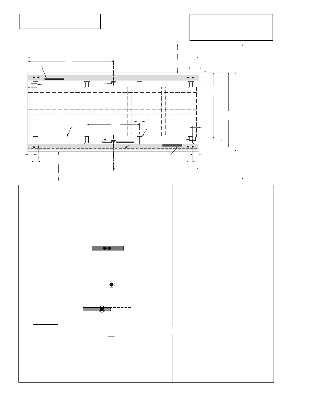
26
1
/2
(673)
5 5/8
(143)
Refrig. Outlet
A
B
Front Relay & Terminal
Block Location
Front
5-Door Shown
6
(152)
63 1/4
(1607)
72 3/8
(1838)
9 1/8
(232)
Electrical Wireway
70 1/8
(1780)
Bottom
Front
Support
48
(1219)
4
(102)
Skid/
External
Base
Electrical Wireway
1 3/4
(44)
4
(102)
Refrig. Outlet
Rear Relay & Terminal Block Location
1 3/4
(44)
7
(178)
Splashguard
B
60 5/8
(1541)
Waste Outlet
26
1
/2
(673)
125 3/8
(3185)
Door Swing
Door Swing
Dimensions shown as in. & (mm).
Serial Plate attached to top left front of each case.
2 Dr 3 Dr 4 Dr 5 Dr
General
(A) Case Length (without ends or partitions) 62 (1575) 92 1/2 (2350) 122 7/8 (3121) 153 3/8 (3896)
Maximum O/S dimension of case back to front 72 3/8 (1837) 72 3/8 (1837) 72 3/8 (1837) 72 3/8 (1837)
(Includes bumper)
Back of case to rear of splashguard 68 1/2 (1740) 68 1/2 (1740) 68 1/2 (1740) 68 1/2 (1740)
Width of Skidrail 3 3/4 (95) 3 3/4 (95) 3 3/4 (95) 3 3/4 (95)
Width of Bottom Front Support 6 (152) 6 (152) 6 (152) 6 (152)
Stub-up area between front skidrail and splashguard 9 (229) 9 (229) 9 (229) 9 (229)
Electrical Service
RH end of case to the center of nearest knockout 4 (102) 4 (102) 4 (102) 4 (102)
RH end of case to the center of LH knockout 58 (1473) 88 1/2 (2248) 118 7/8 (3019) 149 3/8 (3794)
Back O/S of case to center of knockout 70 1/8 (1781) 70 1/8 (1781) 70 1/8 (1781) 70 1/8 (17810)
* NOTE: Electrical Field Wiring Connection Point is at terminal.
Waste Outlet
(B) Right end of case to center of waste outlet 23 7/8 (606) 54 1/4 (1378) 46 1/4 (1175) 76 5/8 (1946)
Back O/S of case to center of waste outlet 63 1/4 (1607) 63 1/4 (1607) 63 1/4 (1607) 63 1/4 (1607)
Water Seal
Edge of water seal to center of waste outlet 13 (330) 13 (330) 13 (330) 13 (330)
Schedule 40 drip piping 1 1/4 (32) 1 1/4 (32) 1 1/4 (32) 1 1/4 (32)
** NOTE: Field installed water seal outlets, tees, and connectors are shipped with case
Refrigeration Outlet
RH end of case to center of RH refrigeration outlet 5 5/8 (143) 5 5/8 (143) 5 5/8 (143) 5 5/8 (143)
Back O/S of case to center of refrigeration outlet 60 5/8 (1541) 60 5/8 (1541) 60 5/8 (1541) 60 5/8 (1541)
Outside bottom front supports from end of case 7 (178) 7 (178) 7 (178) 7 (178)
Center bottom front support from Centerline 24 (610) 24 (610) 24 (610) 24 (610)
Distance between Center and Outside supports will vary
06-2009
PHYSICAL DATA
Merchandiser Drip Pipe (in.) 1 1/4
Merchandiser Liquid Line (in.)
3
/8
Merchandiser Suction Line (in.)
7
/8
RLNI Plan View
2, 3, 4, & 5 Door
Engineering Plan Views
REFRIGERATION DATA
Note: This data is based on store temperature
and humidity that does not exceed 75°F and
55% R.H.
FF IC
Discharge Air (°F) –5 –12
Evaporator(°F) –11 –19
Unit Sizing (°F) –14 –22
Btu/hr/door/side* FF IC
Parallel
1180 1244
Conventional
1200 1270
*Optional LED lighting reduces the
refrigeration load by 100 Btu/hr/Door.
Optional Energy Efficient Fan motors
reduce refrigeration load by 109
Btu/hr/door/side.
DEFROST DATA
FF IC
Frequency (hr) 24 24
Defrost Water
(lb/Dr/side/day)
1.2 1.2
(± 15% based on case configuration and
product loading).
E
LECTRIC
FF IC
Temp Term (°F) 48° 48°
Failsafe (minutes) 45 45
GAS
Duration (minutes) 20 20
O
FFTIME Not Recommended
CONVENTIONAL CONTROLS
Low Pressure Backup Control
FF IC
CI/CO (Temp °F)** –18°/ –34° – 26°/ –45°
Indoor Unit Only, Pressure Defrost
Termination (Temp °F)**
Not Recommended
**Use a Temperature Pressure Chart to
determine PSIG conversions.
Estimated Charge per Side (lb)***
2Dr 1.8
3Dr 2.7
4Dr 3.6
5Dr 4.6
***This is an average for all refrigerant
types. Actual refrigerant charge may vary
by approximately half a pound.
Length Added to Lineup by each
Standard End (in.) 2
Optional End with Window (in.) 1
1
/2
Optional Partition (in.) 1 1/2
Impact RLNI
With INNOVATOR Doors
Frozen Food & Ice Cream
3 of 8P/N 0435492_J
HUSSMANN CORPORATION • BRIDGETON, MO 63044-2483 U.S.A. • WWW.HUSSMANN.COM
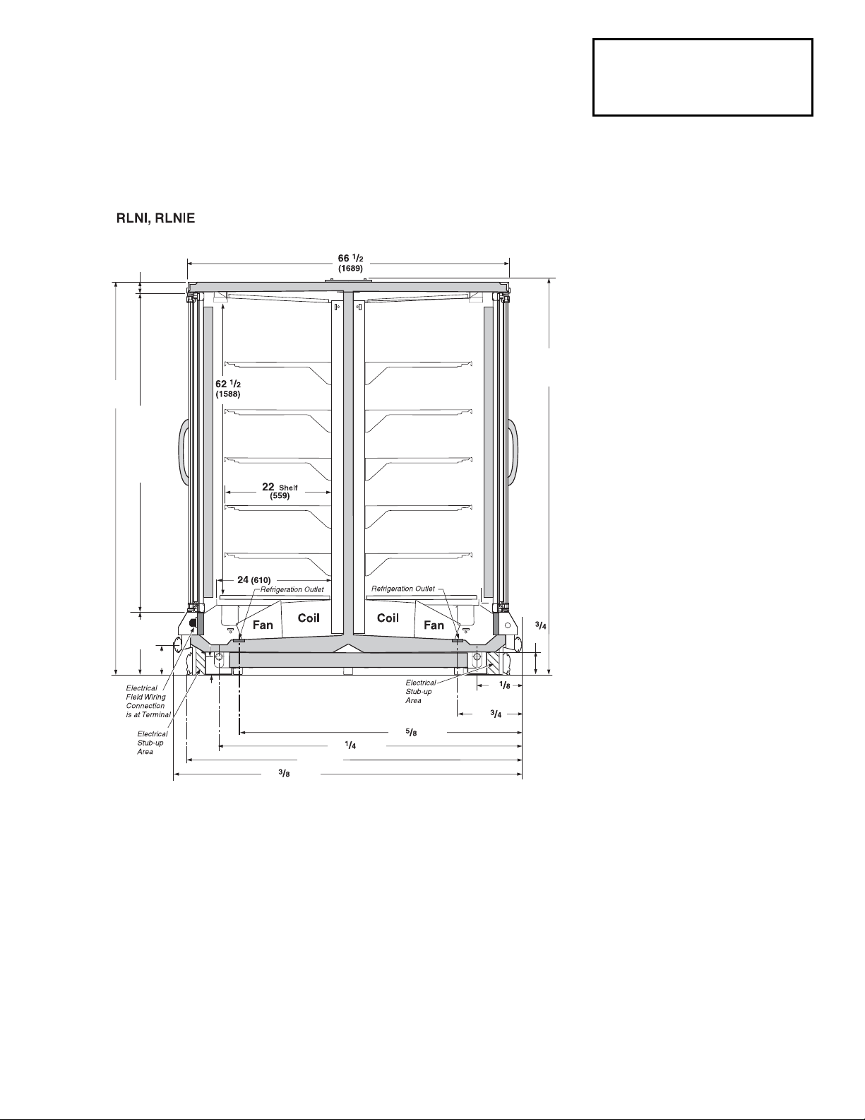
72 (1838)
70 (1778)
4
(121)
11
(298)
83
(2108)
2
1
/8
(54)
67
(1702)
Frame
65 1/2
(1664)
Door
82 1/4
(2089)
13 1/8
(333)
Frame
6
1
/4
(159)
9
(232)
63 (1607)
60 (1540)
3 1/2
(89)
Dimensions shown as in. & (mm).
Reach-in Narrow Island 2, 3, 4 and 5 Door Models
INNOVATOR Doors Standard
Refrigeration data is PER SIDE.
NSF Certification
This merchandiser model is manufactured to meet ANSI/NSF
(National Sanitation Foundation) Standard #7 requirements for
construction, materials & cleanability.