

Page 1
E
F
C
G
B
I
A
J
K
D
H
M
L
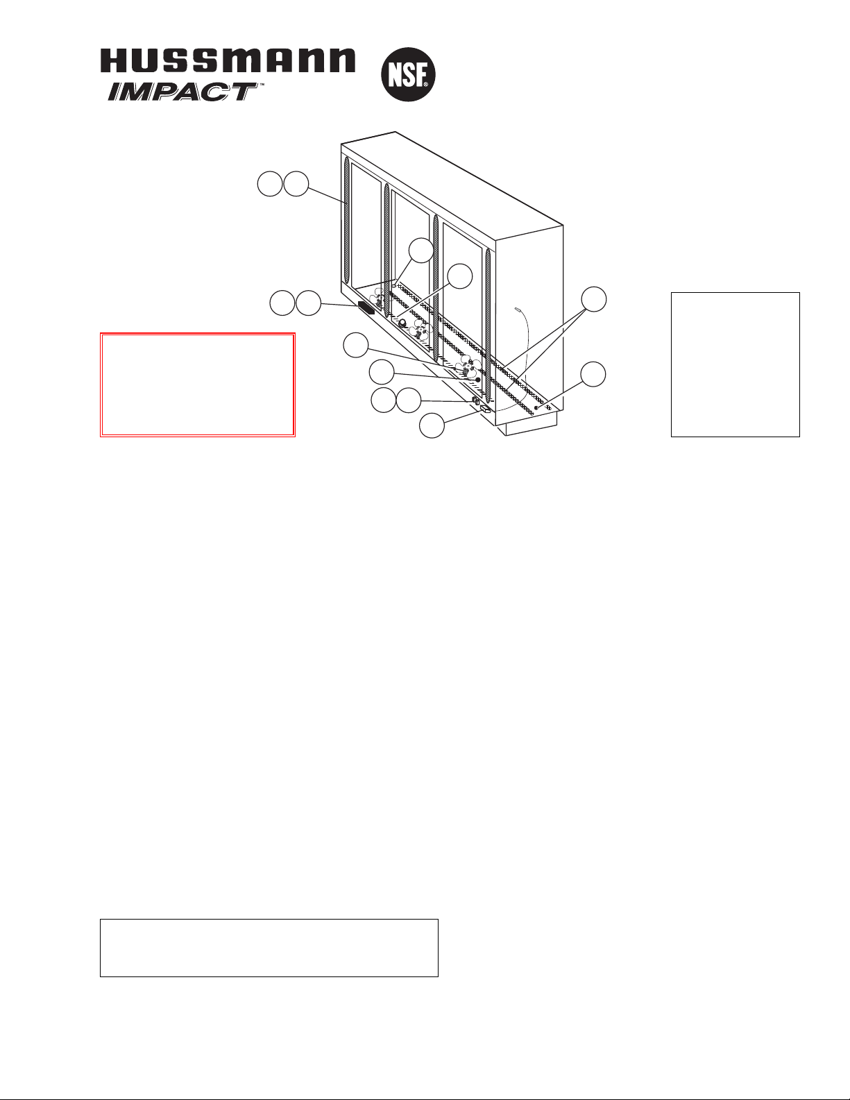
Merchandisers
®
RL
with INNOVATOR II
No Heat Doors
Technical Data Sheet
P/N 0440999_J
NSF
®
Certified
November 2009
Item Part # Description Wiring Item #
FAN ASSEMBLIES, AND THERMOSTATS
A. 12W Standard Fan Assembly (1)
0047000 Fan Motor, Evaporator
(MO.4410103)
0461805 Fan Blade (FB.4780446)
12W Optional Energy Efficient Fan Assembly (1)
0477655 Fan Motor, Evaporator
(MO.4410546)
0461805 Fan Blade (FB.4780446)
B. 0474033 Standard Non-adjustable (2)
Defrost Thermostat (CT.4440726)
C. Optional Adjustable
Refrigeration Thermostat (3)
D. 0344662 Defrost Limit Thermostat (4)
(CT.4440261)
E. 0461814 Relay Control Thermostat or (5)
Fan and Anti-sweat Heater
Thermostat (CT.4481296)
RELAYS
F. 0342598 Anti-Sweat Control Relay (6)
(120V) (RL.4480238)
G. 0342599 Fan Control Relay (208V) (7)
(RL.4480237)
Item Part # (Qty) Description Wiring Item #
HEATERS
H. Electric Defrost Heaters – Front (208V) (8)
0441755 (1) 2 Door Models (HE.4850346)
0441756 (1) 3 Door Models (HE.4850337)
0441757 (1) 4 Door Models (HE.4850347)
0441758 (1) 5 Door Models (HE.4850323)
Electric Defrost Heaters — Rear (208V) (8)
0463891 (1) 2 Door Models (HE.4850358)
0463892 (1) 3 Door Models (HE.4850359)
0463893 (1) 4 Door Models (HE.4850360)
0463894 (1) 5 Door Models (HE.4850361)
I. Drain Pan Heater (Electric & Kool Gas) (9)
(120V)
0387036 (1) 2 Door Models (HE.4850239)
0387037 (1) 3 Door Models (HE.4850240)
0387038 (1) 4 Door Models (HE.4850241)
0387039 (1) 5 Door Models (HE.4850242)
LAMPS, BALLASTS, LED FIXTURES AND POWER SUPPLY
J. 0430330 2 Lamp Ballast (BA.4480342)
0454319 3 Lamp Ballast (BA.4480601)
0424649 Export Ballast (BA.0424649)
K. Standard Fluorescent Lamp
Replace with like fixtures
L. 0499399 LED Power Supply (EP.4481668)
M. LED Fixture
Replace with like fixtures
NOTE: For LED lighting parts contact your Hussmann
service representative at 1-800-922-1919. Please have
your model and serial number available.
We reserve the right to change
or revise specifications and
product design in connection
with any feature of our
products. Such changes
do not entitle the buyer to
corresponding changes,
improvements, additions or
replacements for equipment
previously sold or shipped.
Warning:
Terminal block NOT for
case-to-case
wire connection!
©2009 HUSSMANN CORPORATION • BRIDGETON, MO 63044-2483 U.S.A.
U.S. & CANADA 1-800-922-1919 • MEXICO 1-800-522-1900 • WWW.HUSSMANN.COM
Refer to INNOVATOR REACH-IN GLASS DOOR
INSTALLATION AND SERVICE manual, P/N 0425683,
for Innovator II door and frame replacement parts.
P/N0440999J
NOTE: Revision J updates electrical data, Page 4.
Page 2
RL with Innovator II Doors Technical Data Sheet
2 of 7
HUSSMANN • U.S. & CANADA 1-800-922-1919 • MEXICO 1-800-522-1900
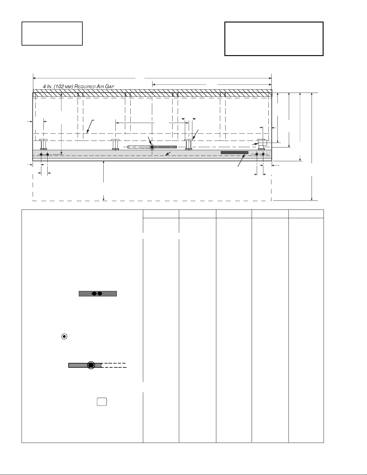
1 Dr 2 Dr 3 Dr 4 Dr 5 Dr
General
(A) Case Length
(without ends or partitions) 31
1
/
2 (800) 62 (1575) 92
1
/
2 (2350) 122
7
/
8 (3121) 153
3
/
8 (3896)
(Each end adds 2 in. (51 mm) to length of lineup; each insulated partition adds 1 1/
2 in. (38 mm).
Maximum O/S dimension of case back to front 43 3/
4 (1111) 43
3
/
4 (1111) 43
3
/
4 (1111) 43
3
/
4 (1111) 43
3
/
4 (1111)
(Includes bumper. Add 26 1/
2 in. (673 mm) for door swing.)
Back of case to rear of splashguard 39 7/
8 (1013) 39
7
/
8 (1013) 39
7
/
8 (1013) 39
7
/
8 (1013) 39
7
/
8 (1013)
Width of Skidrail 3
3
/
4 (95) 3
3
/
4 (95) 3
3
/
4 (95) 3
3
/
4 (95) 3
3
/
4 (95)
Width of Bottom Front Support 6 (152) 6 (152) 6 (152) 6 (152) 6 (152)
Stub-up area between front support and splashguard 3
1
/8 (79) 3 1/8 (79) 3 1/8 (79) 3 1/8 (79) 3 1/8 (79)
Electrical Service
RH end of case to the center of nearest knockout 4 (102) 4 (102) 4 (102) 4 (102) 4 (102)
RH end of case to the center of LH knockout 27 1/
2 (698) 58 (1473) 88
1
/
2 (2248) 118
7
/
8 (3019) 149
3
/
8 (3794)
Back O/S of case to center of knockout 41
5
/
8 (1058) 41
5
/
8 (1058) 41
5
/
8 (1058) 41
5
/
8 (1058) 41
5
/
8 (1058)
* NOTE: Electrical Field Wiring Connection Point is at terminal.
Waste Outlet
(B) Right end of case to center of waste outlet 15 3/
4 (400) 23
7
/
8 (606) 54
1
/
4 (1378) 46
1
/
4 (1175) 76
5
/
8 (1946)
Back O/S of case to center of waste outlet 34
5
/
8 (879) 34
5
/
8 (879) 34
5
/
8 (879) 34
5
/
8 (879) 34
5
/
8 (879)
Water Seal
Edge of water seal to center of waste outlet 13 (330) 13 (330) 13 (330) 13(330) 13 (330)
Schedule 40 PVC drip pipe 1
1
/
4 (32) 1
1
/
4 (32) 1
1
/
4 (32) 1
1
/
4 (32) 1
1
/
4 (32)
** NOTE: Field installed water seal outlets, tees, and connectors are shipped with case
Refrigeration Outlet
RH end of case to center of RH refrigeration outlet 5 3/
8 (137) 5
3
/
8 (137) 5
3
/
8 (137) 5
3
/
8 (137) 5
3
/
8 (137)
Back O/S of case to center of refrigeration outlet 32 (813) 32 (813) 32 (813) 32(813) 32 (813)
Outside bottom front supports from end of case 6
3
/
4 (170) 6
3
/
4 (170) 6
3
/
4 (170) 6
3
/
4 (170) 6
3
/
4 (170)
Center bottom front support from Centerline NA 24 (610) 24 (610) 24 (610) 24 (610)
Distance between Center and Outside supports will vary
4
(102)
43
3
/4
(1111)
Front
5-Door Shown
6
(152)
34
5
/8
(879)
32
(813)
5
5
/8
(143)
41
5
/8
(1057)
Refrig. Outlet
A
B
Electrical Wireway
Bottom
Front
Support
48
(1219)
Waste Outlet
Relay & Terminal
Block Location
Skid/
External
Base
13/4
(44)
13/4
(44)
7
(178)
4
(102)
Splashguard
Clearance for Door Swing
26
1
/2
(673)
70
1
/4
(1784)
Dimensions shown as in. & (mm).
Reach-In
2, 3, 4 & 5 Door
Engineering
Plan Views
PHYSICAL DATA
Merchandiser Drip Pipe (in.) 1 1/4
Merchandiser Liquid Line (in.)
3
/8
Merchandiser Suction Line (in.)
7
/8
RL - RM - RMF
Plan View
06-2009
Page 3
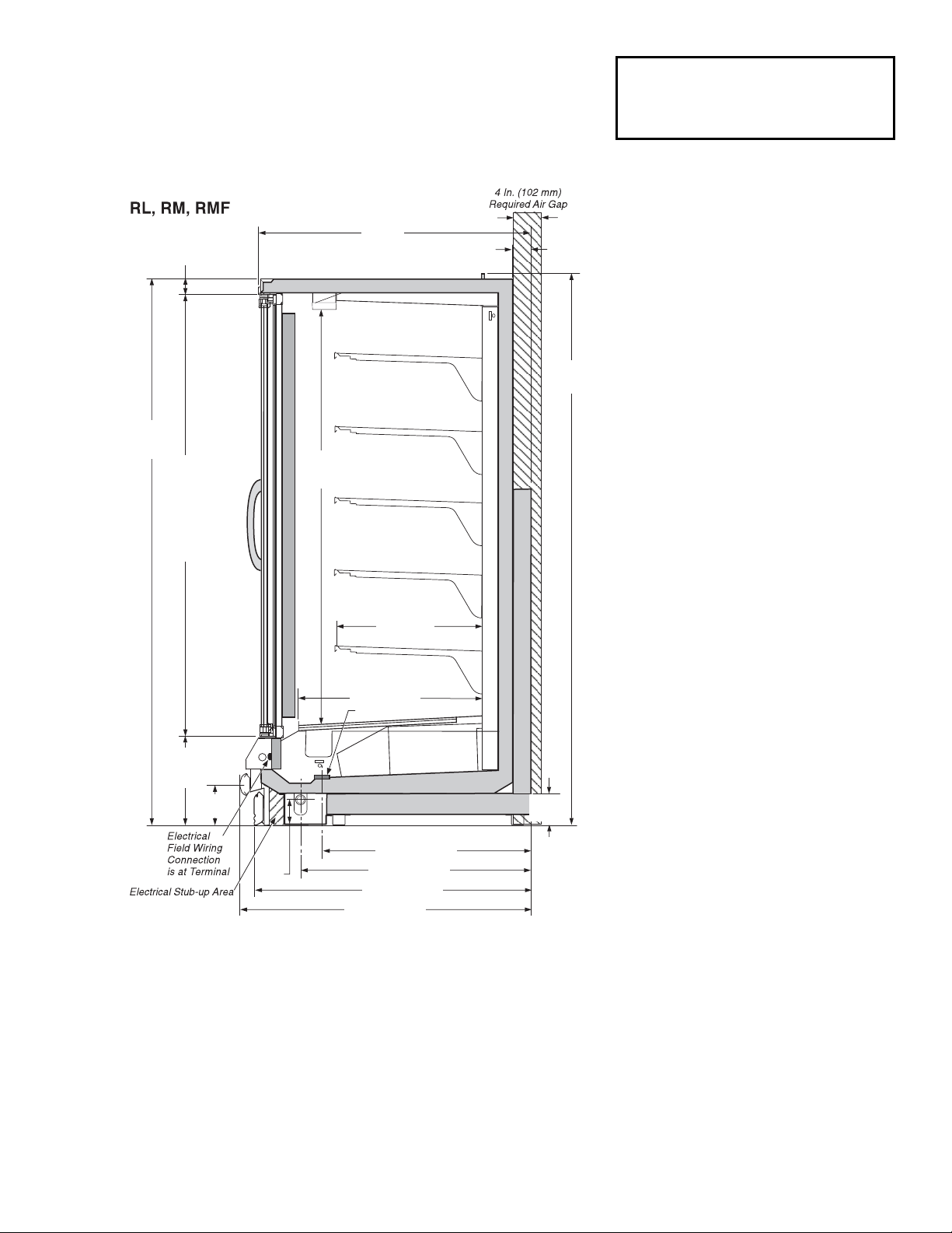
Impact RL
With INNOVATOR II Doors
Frozen Food & Ice Cream
REFRIGERATION DATA
Note: This data is based on store temperature and
humidity that does not exceed 75°F and 55% R.H.
FF IC
Discharge Air (°F) –5 –12
Evaporator (°F) –9 –17
Unit Sizing (°F) –12 –20
Btu/hr/Door
†
FF IC
Parallel
1195 1258
Conventional
1220 1310
†Optional LED lighting reduces refrigeration
load by 100 Btu/hr/Door.
Optional Energy Efficient Fan motors reduce
refrigeration load by 109 Btu/hr/Door.
DEFROST DATA
FF IC
Frequency (hr) 24 24
Defrost Water (lb/Dr/day) 1.2 1.2
(± 15% based on case configuration and
product loading.)
ELECTRIC FF IC
Temp Term (°F) 48° 48°
Failsafe (minutes) 45 45
GAS
Duration (minutes) 20 20
O
FFTIME Not Recommended
CONVENTIONAL CONTROLS
Low Pressure Backup Control
FF IC
CI/CO (Temp °F)** -18°/ -34° - 26°/-45°
Indoor Unit Only, Pressure Defrost
Termination (Temp °F)**
Not Recommended
**Use a Temperature Pressure Chart to
determine PSIG conversions.
Estimated Charge (lb)***
2Dr 1.8
3Dr 2.7
4Dr 3.6
5Dr 4.6
***This is an average for all refrigerant types.
Actual refrigerant charge may vary by approximately half a pound.
Length Added to Lineup by each
Standard End (in.) 2
Optional End with Window (in.) 1
1
/
2
Optional Partition (in.) 1 1/
2
Reach-in 2, 3, 4 and 5 Door Models
3 of 7P/N 0440999_J
HUSSMANN CORPORATION • BRIDGETON, MO 63044-2483 U.S.A. • WWW.HUSSMANN.COM
4 3/4
(121)
32 (813)
34 5/8 (879)
2 5/8
(67)
2
1
/8
(54)
Fan
Coil
62 1/2
(1588)
22 Shelf
(559)
41
(1041)
27 7/8 (708)
Refrigeration Outlet
67
(1702)
Frame
65 1/2
(1664)
Door
83
(2108)
82 1/4
(2089)
6
1
/4
(159)
13 1/8
(333)
Frame
41 7/8 (1064)
43 3/4 (1111 )
3 1/2
(89)
Dimensions shown as in. & (mm).
NSF Certification
This merchandiser model is manufactured to meet ANSI/NSF
(National Sanitation Foundation) Standard #7 requirements for
construction, materials & cleanability.
Page 4

HUSSMANN • U.S. & CANADA 1-800-922-1919 • MEXICO 1-800-522-1900
Electrical Data
2Dr 3Dr 4Dr 5Dr
Number of Fans—12W 2 3 4 5
Amperes Watts
Merchandiser 2Dr 3Dr 4Dr 5Dr 2Dr 3Dr 4Dr 5Dr
Evaporator Fan
120V 60Hz Standard 1.30 1.95 2.60 3.25 100 150 200 250
120V 50Hz Standard 1.50 2.25 3.00 3.75 114 171 228 285
220V 60Hz Export 0.66 0.99 1.32 1.65 100 150 200 250
220V 50Hz Export 0.76 1.14 1.52 1.90 114 171 228 285
120V 60Hz Energy Efficient 0.60 0.90 1.20 1.50 36 54 72 90
220V 60Hz Energy Efficient 0.30 0.45 0.60 0.75 36 54 72 90
Door Anti-sweat Heaters (on fan circuit) NA
Frame Anti-sweat Heaters (on fan circuit)
120V 50/60Hz Standard 0.89 1.34 1.79 2.24 107 161 215 269
220V 50/60Hz Export 0.49 0.73 0.98 1.22 107 161 215 269
Minimum Circuit Ampacity
120V 60Hz Standard 2.39 3.49 4.59 5.69
120V 50Hz Standard 2.59 3.79 4.99 6.19
220V 60Hz Export 1.35 1.92 2.50 3.07
220V 50Hz Export 1.45 2.07 2.70 3.32
120V 60Hz Energy Efficient 1.69 2.44 3.19 3.94
220V 60Hz Energy Efficient 0.99 1.38 1.78 2.17
Maximum Over Current Protection 120V 20 20 20 20
Maximum Over Current Protection 220V 15 15 15 15
Defrost
Drain Heaters (120V) 0.63 1.25 2.00 2.57 75 150 240 300
(Export: 220V 50 Hz) 0.34 0.76 1.22 1.53 84 168 269 336
208V Electric Defrost 6.72 10.08 13.46 16.82 1400 2100 2800 3500
(Export: 220V 50 Hz) 7.11 10.66 14.24 17.79 1564 2345 3133 3914
Standard Vertical Lighting 2Dr 3Dr 4Dr 5Dr 2Dr 3Dr 4Dr 5Dr
Innovator* Doors (120V) 1.50 2.00 2.50 3.00 180 240 300 360
(Export: 220V 50 Hz) 0.84 1.12 1.40 1.68 185 246 308 370
Optional LED Lighting
Hussmann EcoShine™ [27 W] (120V) 0.45 0.68 0.90 1.13 54 81 108 135
Hussmann EcoShine™
[27 W] [220V (Export)] 0.25 0.37 0.49 0.61 54 81 108 135
Hussmann EcoShine™ EP [16 W] (120V) 0.27 0.40 0.53 0.67 32 48 64 80
Hussmann EcoShine™
EP [16 W] [220V (Export)] 0.15 0.22 0.29 0.36 32 48 64 80
Hussmann EcoShine™ [20 W] (120V) 0.33 0.50 0.67 0.83 40 60 80 100
Hussmann EcoShine™
[20 W] [220V (Export)]
0.17 0.25 0.33 0.42 40 60 80 100
Gelcore (120V) 0.48 0.73 0.97 1.21 58 87 116 145
Gelcore (120V)
[220V (Export)]
0.26 0.40 0.53 0.66 58 87 116 145
* Innovator or Innovator II
RL with Innovator II Doors Technical Data Sheet
4 of 7
Impact RL
With INNOVATOR II Doors
Frozen Food & Ice Cream
Hussmann recommends against frame heater cycling with
Innovator
doors to prevent door seals from freezing to the
frames and tearing.
Page 5

5 of 7P/N 0440999_J
HUSSMANN CORPORATION • BRIDGETON, MO 63044-2483 U.S.A. • WWW.HUSSMANN.COM
ESTIMATED SHIPPING WEIGHT
5
Case Solid End
1 Dr 2 Dr 3 Dr 4 Dr 5 Dr (each)
lb (kg) NA (NA) 997 (453) 1295 (589) 1595 (725) 1874 (852) 55 (25)
5
Actual weights will vary according to optional kits included.
Product Data
Recommended Usable Cube
1
(Cu Ft/Dr) 23.46 ft3 /Dr (0.66 m3 /Dr)
ARI Total Display Area
2
(Sq Ft/Dr) 13.31 ft2/Dr (1.24 m2 /Dr)
Shelf Area 3(Sq Ft/Dr) 29.32 ft2/Dr (2.72 m2 /Dr)
1
ARI Refrigerated Volume less shelving and other unusable space: Refrigerated Volume/Unit of Length, ft3/ft [m3/m]
2
Computed using ARI 1200 standard methodology: Total Display Area, ft2[m2]/Unit of Length, ft [m]
3
Shelf surface area is composed of bottom deck plus standard shelf complement, as shown in the Hussmann
Product Reference Guide. The standard shelf complement for this model is (5) rows of 22-inch shelves.
Impact RL
With INNOVATOR II Doors
Frozen Food & Ice Cream
Page 6

RL with Innovator II Doors Technical Data Sheet
6 of 7
OR
120V POWER
OR
Switch
NEUTRAL
17
20
Defrost Termination
Thermostat
Refrigeration
Thermostat
(Optional)
Pink
2
3
}
To
Condensing
Unit
A.S. Relay
Coil
BR
Evaporator Fans
1
Fan Relay
F
COM
N.O.
Rod Heater (Drain)
9
Y
Y
N.C.
7
7
1
3
W
Relay Control
c
25
Fan Relay
F
5
6
BK
COM
N.C.
6
A.S. Relay
A.S.
24
Door A.S. Heaters
Frame A.S. Heaters
21
22
2P
P
2P
P
12
11
10
120V POWER
16
13
Evaporator Fan
Relay Coil
1
3
Rear Defrost Heater
R
R
C
8
R
R
Front Defrost Heater
R
5
4
7
R
N.C.
7
8
8
Defrost Limit
208V
208V
Terminal Blocks in Raceway
Low Temperature with
Electric Defrost
20
21
22
26
17
1234
56 7
81011 1413 16
LIGHTS
(120V)
DEFROST HEATERS
(208V)
CIRCLED NUMBERS = PARTS LIST ITEM NUMBERS
THESE ARE MARKER COLORS (WIRE MAY VARY.)
CAUTION: When multiplexing
merchandisers equipped with defrost
heaters, if branch circuit overcurrent
protection is larger than the
circuit load, then additional
supplemental overcurrent protection
may be required per NEC Articles
210 and 240.
R = Red P = Purple 2P = Purple (2 Bands) DB = Dark Blue BL = Black
LB = Light Blue BR =Brown Y =Yellow OR = Orange W = White
Low Temperature
24 2512
FANS & A.S.
(120V)
LIGHTS
(Neutral)
FANS & A.S. (Neutral)
Permanent Internal
Jumpers
R P
W
BRORRRRBKBKRRBKP
2P
BK BK ORBK 2P Y
14
26
C.O.R.
1
2
3
4
6
O.O.R.
Removable External
Jumpers
DB
C.O.R.
2
Defrost Termination
Thermostat
FIELD WIRED
DB
NEUTRAL
Dark Blue
Refer to Innovator Reach-In
Glass Door, Installation and
Service manual, P/N 0425683,
for Innovator door and frame
replacement parts.
BK
BK
BK
BK
BK
Electric Defrost Sequence - Low Temperature
1. Power from the defrost contactor energizes Defrost Heaters and 208V Evaporator Fan Relay Coil (7). Relay Contacts open the fan
circuit and energizes the Drain Pan Heater.
2. If the Defrost Heater raises internal air temperature above 90°F, the Defrost Limit Thermostat (4) will open.
3. Temperature rise of the evaporator closes the Relay Control Thermostat (5) at about 35°F, energizing 120V A.S. Relay Coil (6).
This relay’s contacts open the Frame and Door Heater Circuits.
4. When Defrost Termination Thermostat ends defrost period, the defrost contactor opens the Defrost Heater and Evaporator Fan
Relay Coil Circuits. The Drain Pan Heater goes off and fans are on.
5. Temperature fall of the evaporator opens the Relay Control Thermostat (5) at about 20°F, de-energizing 120V A.S. Relay Coil (6).
A.S. Relay Contacts close the Frame and Door Heater Circuits.
HUSSMANN • U.S. & CANADA 1-800-922-1919 • MEXICO 1-800-522-1900
Page 7

7 of 7P/N 0440999_J
HUSSMANN CORPORATION • BRIDGETON, MO 63044-2483 U.S.A. • WWW.HUSSMANN.COM
CIRCLED NUMBERS = PARTS LIST ITEM NUMBERS
THESE ARE MARKER COLORS (WIRE MAY VARY.)
R = Red P = Purple 2P = Purple (2 Bands) DB = Dark Blue BL = Black
LB = Light Blue BR =Brown Y =Yellow OR = Orange W = White
Permanent Internal
Jumpers
A.S. Relay
Coil
BR
Evaporator Fans
1
Fan Relay
F
COM
N.O.
Rod Heater (Drain)
9
Y
Y
N.C.
7
7
1
3
W
Relay Control
c
25
Fan Relay
F
BK
5
6
COM
N.C.
6
A.S. Relay
A.S.
24
Door A.S. Heaters
Frame A.S. Heaters
22
2P
2P
P
12
10
120V POWER
13
26
C.O.R.
P
OR
120V POWER
OR
Switch
NEUTRAL
17
20
Terminal Blocks in Raceway
Low Temperature with
Gas Defrost
20
21
22
26
17
10 11 1413 16
LIGHTS
(120V)
Refrigeration
Thermostat
(Optional)
Pink
3
}
To
Condensing
Unit
24 2512
FANS & A.S.
(120V)
LIGHTS
(Neutral)
FANS & A.S. (Neutral)
P
W
BRORBK P
2P
BK BK ORBK 2P Y
Removable External
Jumpers
Low Temperature
16
7
Fan Relay
Coil
11
c
Defrost Limit
4
O.O.R.
14
21
NEUTRAL
Refer to Innovator Reach-In
Glass Door, Installation and
Service manual, P/N 0425683,
for Innovator door and frame
replacement parts.
BK
BK
BK
Gas Defrost Sequence - Low Temperature
1. Defrost vapor enters evaporator causing a rise in temperature. At about 35°F the Control Relay Thermostat
(5) closes
the Fan Relay Coil (7) and Control Relay Coil (6) circuit. The Coil opens the Fan, Door Heater, and Frame Heater cir-
cuits, while energizing the Drain Pan Heater
(9).
2. If the Drain Pan Heater (9) raises internal air temperature above 90°F, the Heater Limit Thermostat (4) will open.
3.
When the defrost timer ends a defrost period, the evaporator temperature will start to fall. At about 20°F, the Control
Relay Thermostat will open, de-energizing the Control Relay Coil and Fan Relay Coil (7). Control and Fan Relay’s will
open the Drain Pan Heater circuits, and will close the Fan, Door Heater, and Frame Heater circuits.
 Loading...