


REV.
Manual
Installation
& Operation
/Chino
RID
ROLL IN DELI/DAIRY DISPLAY
9610(9911)
RID
ROLL IN DELI/DAIRY DISPLAY
P/N IGUP-RID-9610(9911)
INSTALLATION & OPERATION GUIDE

Ta b l e of Contents
IGUP-RID-9610(9911)
General Instructions
THIS BOOKLET CONTAINS INFORMATION ON:
General Instructions ................................................. 2
Cut & Plan Views ....................................................... 3
Installation ................................................................. 4
LEVELING.............................................................................................................. 4
JOINING ................................................................................................................ 4
Plumbing .................................................................... 5
WASTE OUTLET AND P-TRAP .............................................................................. 5
Refrigeration ............................................................. 6
Electrical .................................................................... 7
WIRING COLOR CODE ......................................................................................... 7
User Information ...................................................... 8
STOCKING.............................................................................................................. 8
CASE CLEANING.................................................................................................... 8
Maintenance .............................................................. 9
ELECTRICAL PRECAUTIONS ................................................................................... 9
REPLACING FLUORESCENT LAMPS ....................................................................... 9
TIPS & TROUBLESHOOTING ................................................................................. 9
Electrical and Refrigeration Specifications ............ 10
Electrical Schematics ............................................... 10
Appendices ................................................................ 11
APPENDIX A. – Temperature Guidelines ............................................................ 11
APPENDIX B. – Application Recommendations.................................................. 11
APPENDIX C. – Field Recommendations -......................................................... 11
APPENDIX D. – Recommendations to user - .................................................... 12
RIDStraight-glass refrigerated service meat/fish merchandiser
SHIPPING DAMAGE
All equipment should be thoroughly examined for shipping damage before and during unloading.
This equipment has been carefully inspected at our factory and the carrier has assumed responsibility for safe
arrival. If damaged, either apparent or concealed, claim must
be made to the carrier.
APPARENT LOSS OR DAMAGE
If there is an obvious loss or damage, it must be noted on
the freight bill or express receipt and signed by the carrier’s
agent; otherwise, carrier may refuse claim. The carrier will
supply necessary claim forms.
CONCEALED LOSS OR DAMAGE
When loss or damage is not apparent until after equipment
is uncrated, a claim for concealed damage is made. Make
request in writing to carrier for inspection within 15 days,
and retain all packaging. The carrier will supply inspection
report and required claim forms.
SHORTAGES
Check your shipment for any possible shortages of material. If a shortage should exist and is found to be the responsibility of Hussmann Chino, notify Hussmann Chino. If
such a shortage involves the carrier, notify the carrier imme-
diately, and request an inspection. Hussmann Chino will
acknowledge shortages within ten days from receipt of
equipment.
HUSSMANN CHINO PRODUCT CONTROL
The serial number and shipping date of all equipment has
been recorded in Hussmann’s files for warranty and replacement part purposes. All correspondence pertaining
to warranty or parts ordering must include the serial number of each piece of equipment involved, in order to provide the customer with the correct parts.
Keep this booklet with the case at all times for future reference.
/Chino
A publication of
Hussmann® Chino
13770 Ramona Avenue • Chino, California 91710
(909) 628-8942 FAX
(909) 590-4910
(800) 395-9229
The Hussmann warranty is printed on the back
of this guide.
2
Rev. 9610(9911)
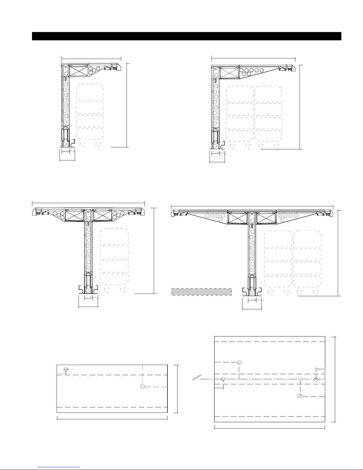
RID01, SINGLE DEPTH
4'-55/16"
Cut & Plan Views
RID03, DOUBLE DEPTH
6'-65/16"
ROLL-IN
CARTS
1
/2"
7
1'1/4"
RID012 SINGLE DEPTH
RID-01
8'-105/8"
ROLL-IN
CARTS
"
4
/
1
6'-11
1'1/4"
ROLL-IN
CARTS
ROLL-IN
CARTS
"
4
/
1
6'-11
1
7
/2"
RID-03
RID04, DOUBLE DEPTH
13'-05/8"
"
4
/
1
ROLL-IN
CARTS
ROLL-IN
CARTS
6'-11
"
4
/
1
6'-11
SINGLE DEPTH
3"
6"
Drain
Elec.
4"
1
7
/2"
1
1'-6
/4"
ELEC. FLEXED ASSEMBLED IN FIELD
DRAIN IS 1" PLASTIC TUBE
REFRIG. STUBBED UP THROUGH TOP
VARIABLE LENGTHS
PLAN VIEW
Single Sided
RID-02
Ref.
FRONT
18"
PALLET
1
/2"
7
1'-61/4"
RID-04
DOUBLE DEPTH
FRONT
Ref.
18"
C
18"
L
Drain
6"
"
4
/
1
14
"
4
/
1
14
Ref.
ELEC. FLEXED ASSEMBLED IN FIELD
SINGLE OR DOUBLE DEPTH
Elec.
4"
DRAIN IS 1" PLASTIC TUBE
REFRIG. STUBBED UP THROUGH TOP
FRONT
VARIABLE LENGTHS
PLAN VIEW
18"
Drain
4"
Elec.
6"
1
SINGLE DEPTH)
DOUBLE DEPTH)
" (
" (
2
8
/
/
5
8'-10
13'-0
3
Installation
LOCATION
The refrigerated merchandisers have been designed for
use only in air conditioned stores where temperature and
humidity are maintained at or below 75°F and 55% relative humidity. DO NOT allow air conditioning, electric fans,
ovens, open doors or windows (etc.) to create air currents around the merchandiser, as this will impair its correct operation.
Product temperature should always be maintained at a
constant and proper temperature. This means that from
the time the product is received, through storage, preparation and display, the temperature of the product must
be controlled to maximize life of the product.
UNCRATING THE STAND
Place the fixture as close to its permanent position as
possible. Remove the top of the crate. Detach the walls
from each other and remove from the skid. Unbolt the
case from the skid. The fixture can now be lifted off the
crate skid. Lift only at base of stand!
EXTERIOR LOADING
These models have not been structurally designed to sup-
port excessive external loading. Do not walk on their
tops; This could cause serious personal injury and damage to the fixture.
SETTING AND JOINING
The sectional construction of these models enable them
to be joined in line to give the effect of one continuous
display. A joint trim kit is supplied with each joint.
LEVELING
Leveling is necessary to insure proper operation, water
drainage and alignment. When joining, use a carpenters
level and shim legs accordingly. Case must be raised
correctly, under legs where support is best, to prevent
damage to case.
The RID case is tall and narrow and can be tipped over if
it is raised too high on one side.
JOINING
IGUP-RID-9610(9911)
(B) 2 Canopies
(C) 2 End Panels - each consisting of 3 pieces plus trim
(D) Top Panel
(E) Floor Track
A special floor Track for the Center Wall and End
Panels has been provided to anchor the case to the floor.
Also enclosed is a special Beam to allow the canopies to
be positioned on the Center Wall with a forklift.
CASE ASSEMBLY
1. Lay out the supplied floor Track in the required
location, and check for level floor in all directions.
2. (a ) If the highest and lowest points are within
1/4" of each other, the Track can be pinned to the
floor, and the case leveled by adding shims between
the case and the Track.
(b) If the Track is out of level by more than 1/
4", the track must be brought back to within 1/4" of
level, by shimming to the floor under the Track. Final
case leveling can now be done as noted before.
3. Position the Center Wall centrally in the wide Track
and level. Fasten to Track using the screws provided.
Add a temporary 2" x 4" wood brace to the end of
the Center Wall to prevent toppling.
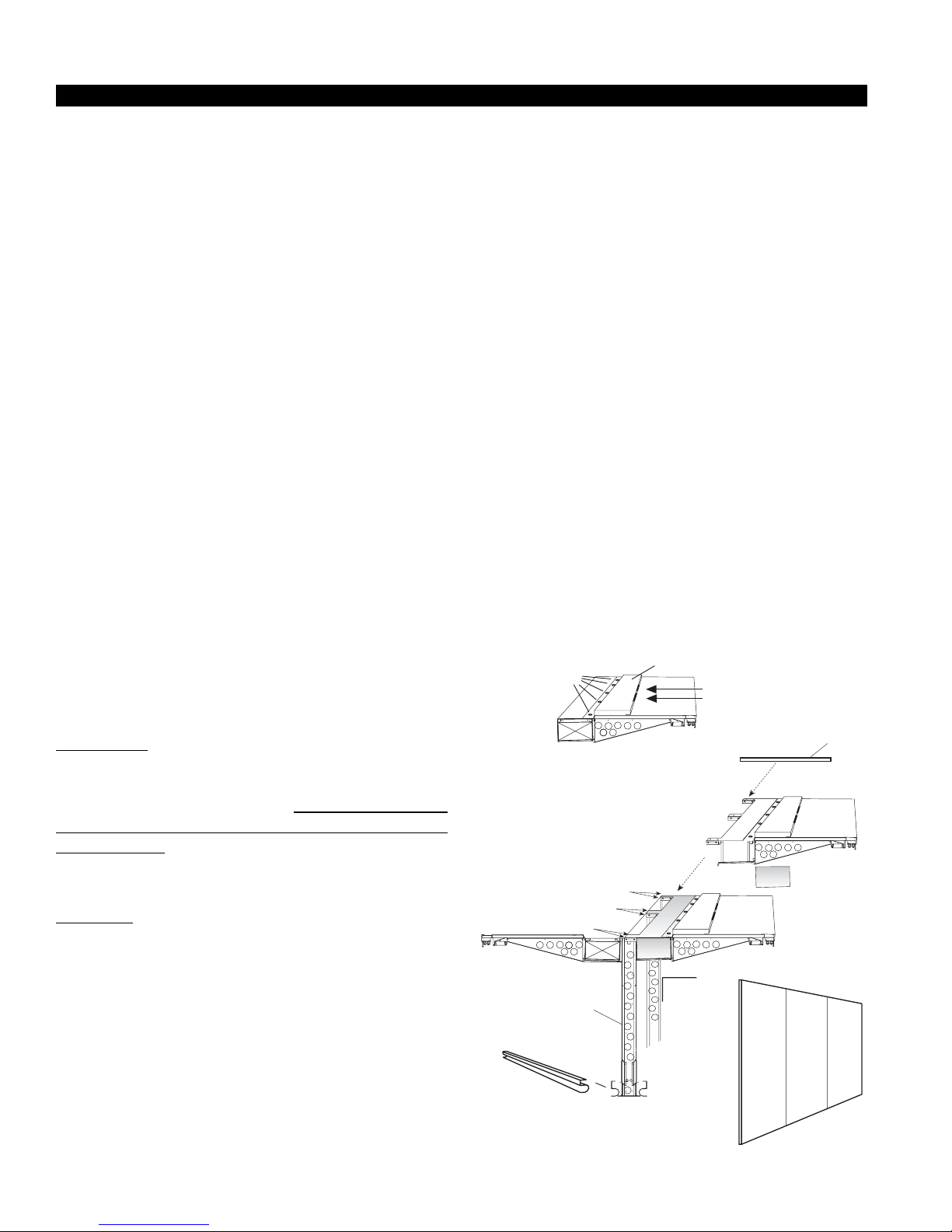
4. Attach the supplied Beam to the top of the first
section of the Canopy using the supplied 5/8"bolts.
CANOPY
BEAM
5 BOLTS
Secure 4 bolts on each
C-channel to wall
supports - every 2' along
case
HOLES FOR
FORKLIFT BLADES
CANOPY
TOP PANEL
NOTE: FOR EASE OF INSTALLATION, IT IS
RECOMMENDED THAT THE UNIT IS ASSEMBLED
BY A CREW OF THREE TO FOUR (3-4) PEOPLE
AND ONE (1) FORKLIFT.
During the development of this product, a simulated field
installation was carried out, to identify the simplest method
of assembly. To reduce installation time and to avoid any
confusion, the case has been pre-assembled into six (6)
main pieces:
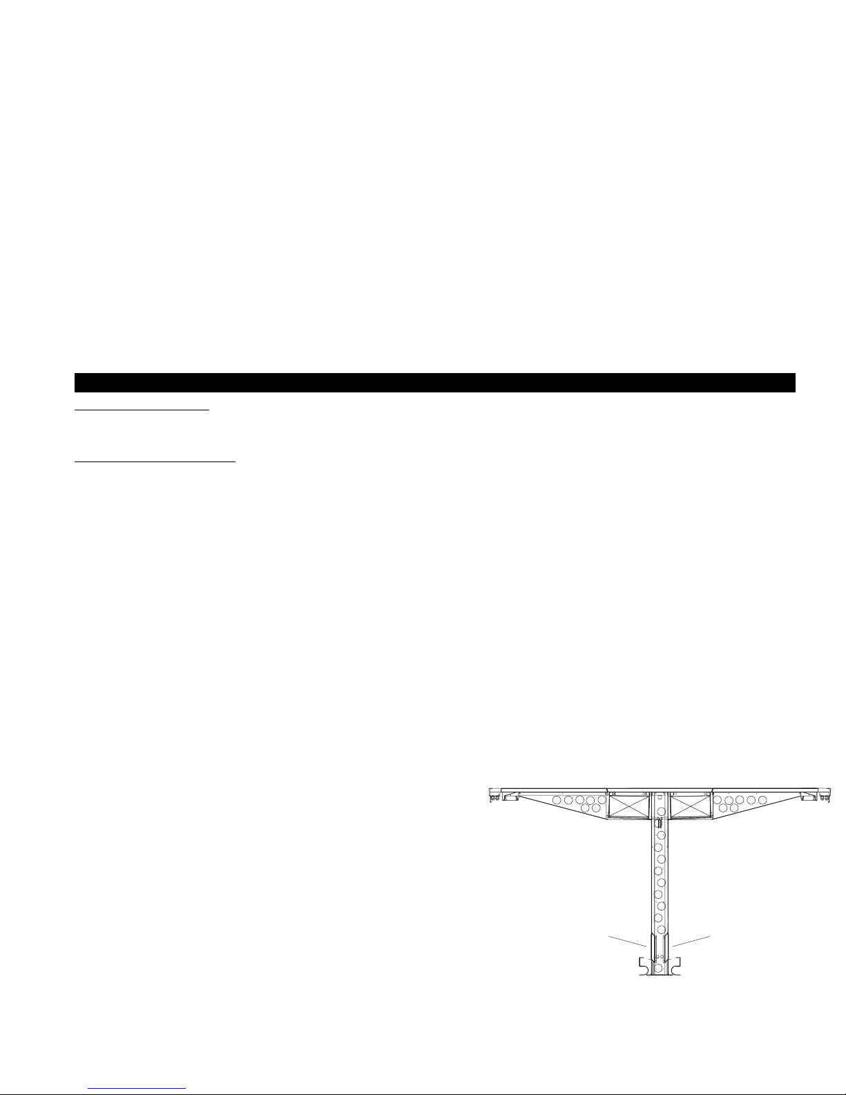
(A) Center Wall
END PANEL
CENTER WALL
FLOOR BUMPER
4
Rev. 9610(9911)
WARNING: DO NOT LET ANY WEIGHT BEAR
DOWN ON THE COIL ASSEMBLY. USE 5
GALLON BUCKETS OR SIMILAR UNDER THE
CANOPY TO HOLD THE WEIGHT WHILE THE
BEAM IS BEING ATTACHED. THE FORK HOLES
ON THE BEAM SHOULD FACE TOWARD THE
OUTSIDE EDGE OF THE CANOPY.
5. Carefully raise and position Canopy on Center Wall
"C" channels. Fasten with screws provided - two on
each side of the C channel. "C" channels are located
every two feet along the length of the case.
6. Screw first panel of both End Panels to the Canopy to
stabilize the case. Shim to level
Plumbing
ACCESS PANELS
The drain line is accessable through a panel on the interior
back wall if the case on the left hand side..
DRAIN AND P-TRAP
The drain line is located on the left hand side of the case.
There are two drain lines for back to back (double sided)
cases.
WASTE OUTLET AND P-TRAP
The waste outlet is located off the center of the case on
one side allowing drip piping to be run lengthwise under
the fixture.
A 1-1/2" P-trap and threaded adapter are supplied with
each fixture. The P-trap must be installed to prevent air
leakage and insect entrance into the fixture.
NOTE: PVC-DWV solvent cement is recommended.
Follow the manufacturer’s instructions.
INSTALLING CONDENSATE DRAIN
Poorly or improperly installed condensate drains can seriously interfere with the operation of this refrigerator,
and result in costly maintenance and product losses. Please
follow the recommendations listed below when installing
condensate drains to insure a proper installation:
1. Never use pipe for condensate drains smaller than
the nominal diameter of the pipe or P-trap supplied
with the case.
2. When connecting condensate drains, the P-trap
must be used as part of the condensate drain to
prevent air leakage or insect entrance. Store
plumbing system floor drains should be at least 14"
off the center of the case to allow use of the P-trap
pipe section. Never use two water seals in series in
any one line. Double P-traps in series will cause a
lock and prevent draining.
After cases have been leveled and joined, and refrigeration, electrical, and wasted piping work completed, install
the splashguards. Fasten along the top edge, or center, with
#10 X 3/3" sheet metal screws.
DO NOT SEAL JOINT T RIM T O FLOOR!
3. Always provide as much down hill slope (“fall”) as
possible; 1/8" per foot is the preferred minimum.
PVC pipe, when used, must be supported to maintain
the 1/8" pitch and to prevent warping.
4. Avoid long runs of condensate drains. Long runs
make it impossible to provide the “fall” necessary for
good drainage.
5. Provide a suitable air break between the flood rim
of the floor drain and outlet of condensate drain. 1"
is ideal.
6. Prevent condensate drains from freezing:
a. Do not install condensate drains in contact with
non-insulated suction lines. Suction lines should
be insulated with a nonabsorbent insulation
material such as Armstrong’s Armaflex.
b. Where condensate drains are located in dead air
spaces (between refrigerators or between a
refrigerator and a wall), provide means to
prevent freezing. The water seal should be
insulated to prevent condensation.
DRAIN ACCESS
LEFT SIDE
DRAIN ACCESS
LEFT SIDE
5
 Loading...