

Page 1

RFLNS & RFMNS
®
Freedom Line
Low or Medium Temperature
Compressor Ready
Narrow Footprint
Reach-in
Merchandisers
IMPORTANT
Keep in store for
future reference!
MANUAL - I/O FREEDOM RFLNS & RFMNS
Installation &
Operation Manual
Shipped With Case Data Sheets
P/N 0539221_H
July 2015
Spanish P/N 0541249
French P/N 0541252
Page 2

Page 3

P/N 0539221_H iii
®
TABLE OF CONTENTS
INSTALLATION
NSF Certication ..................... 1-1
Freedom Line Description
Location
............................. 1-1
.............. 1-1
Shipping Damage ...................... 1-2
Exterior Loading ...................... 1-2
Moving Merchandisers (Narrow Entrance) . 1-2
Merchandisers Shipped with End Installed .. 1-2
Optional Forklift Pockets ............... 1-3
Shipping Braces ....................... 1-3
Leveling ............................. 1-4
Door Adjustment . . . . . . . . . . . . . . . . . . . . . . 1-6
Joining .............................. 1-6
REFRIGERATION / ELECTRICAL
/ SAFE-NET III
Refrigerant ........................... 2-1
Field Installation of Condensing Unit ..... 2-2
About Quick Connect Couplings .......... 2-5
Connect Lines ........................ 2-5
Insulate Refrigerant Lines ............... 2-5
Field Wiring .......................... 2-5
Safe-NET III User Instructions ........... 2-8
Display ..............................2-9
Start-Up .............................2-9
Safe-NET location .................... 2-10
Sequence of Operation ................2-11
Temperature Adjustment .............. 2-12
Alarms and Codes .................... 2-12
Manual Defrost ...................... 2-12
Merchandiser Electrical Data ........... 2-13
Electrical Connections ................. 2-13
Identication of Wiring ................ 2-13
Controls and Adjustments ............. 2-14
FACADE AND SPLASHGUARDS
Install Facade
Air Flow Bafe
........................3-1
....................... 3-3
Installing Splashguards and Brackets ...... 3-4
Sealing Splashguard to Floor ............ 3-5
Installing Bumpers ..................... 3-6
START UP / OPERATION
Expansion Valve Adjustment ............ 4-1
Prior to Start Up Checklist .............. 4-2
Start Up Checklist ..................... 4-2
Defrost .............................. 4-3
Safe-NET III Control Settings
and Operation ........................ 4-3
Checklist After 12 Hour Run Time ........ 4-3
Load Limits .......................... 4-4
Stocking ............................. 4-4
Installing FDA/NSF
Required Thermometer ................ 4-4
MAINTENANCE
Care and Cleaning ..................... 5-1
Cleaning Condensate Float Switch ........ 5-2
Cleaning Condensate Pump & Pan ........ 5-3
Cleaning Honeycomb Assemblies ......... 5-4
Cleaning Stainless Steel Surfaces .......... 5-4
Cleaning Coils ........................ 5-4
Cleaning Under Merchandisers .......... 5-4
Removing Scratches from Bumper ........ 5-4
Top Mount Cleaning & Maintenance ...... 5-5
SERVICE
Replacing Fan Motors and Blades ........ 6-1
Replacing Electric Defrost Heaters ........ 6-2
Replacing Drain Pan Heater Elec & Gas .... 6-3
Replacing Damaged Drain Fitting ........ 6-3
Repairing Aluminum Coil ............... 6-4
OPTIONAL DRIP PIPING
Waste Outlet and Water Seal ............ 7-1
Installing Drip Piping
.................. 7-1
WARRANTY
IMPORTANT
KEEP IN STORE FOR FUTURE REFERENCE
Quality that sets industry standards!
12999 St. Charles Rock Road • Bridgeton, MO 63044-2483
®
®
U.S. & Canada 1-800-922-1919 • Mexico 1-800-890-2900
www.hussmann.com
© 2015 Hussmann Corporation
Page 4
iv Contents
REVISION HISTORY
REVISION H - JULY 2015
Revised checklist GFCI, Page 4-3
Revised Connect lines and Refrigerant Lines,
Page 2-5
REVISION G – March 2015
Removed references on page 3-3 and 5-3
REVISION F – February 2015
Clearance, Page 1-1
REVISION E – October 2014
Added California Warning Page 1-2;
Installing Air Flow Bafe Page 3-3.
Revised fork life pockets, Page 1-3
End photos and text, Page 1-6
Rear Bracket, Page 2-2 Detail A text, Page 2-4
text, Page 2-7 Photo removed Page 3-1, 3-2, changed
page 3-4, New Optional Drip Pipe Section 7
* * * * * * * * * * * * * * * * * * * * * * * * * *
ANSI Z535.5 DEFINITIONS
• DANGER – Indicate[s] a hazardous
situation which, if not avoided, will
result in death or serious injury.
• WARNING – Indicate[s] a hazardous
situation which, if not avoided, could
result in death or serious injury.
• CAUTION – Indicate[s] a hazardous
situation which, if not avoided, could
result in minor or moderate injury.
• NOTICE – Not related to personal injury –
Indicates[s] situations, which if not avoided,
could result in damage to equipment.
REVISION D – July 2014
Updated Cover Photo
REVISION C – July 2014
Original Issue
P/N 05339221_H
U.S. & Canada 1-800-922-1919 • Mexico 1-800-890-2900 • WWW.HUSSMANN.COM
Page 5

P/N 0539221_H 1-1
INSTALLATION
NSF CERTIFICATION
These merchandisers are manufactured to
meet ANSI / National Sanitation Foundation
®
(NSF
) Standard #7 requirements. Proper installation is required to maintain certication.
Near the serial plate, each case carries a label
identifying the type of application for which
the case was certied.
ANSI/NSF-7 Type I – Display Refrigerator / Freezer
Intended for 75°F / 55%RH Ambient Application
ANSI/NSF-7 Type II – Display Refrigerator / Freezer
Intended for 80°F / 55%RH Ambient Application
ANSI/NSF-7 – Display Refrigerator
Intended for Bulk Produce
FREEDOM LINE DESCRIPTION
The Freedom Line RFLNS and RFMNS cases
are designed to be ready for remote installation
of a top-mounted air-cooled condensing unit,
such as Hussmann’s TCLSA through TCMSD
series of condensing units. They are controlled
by the Safe-NET III electronic control. The
case temperature is controlled by cycling the
compressor based on the discharge air
temperature input. The sensor for this input
is located above the discharge air honeycomb.
Another sensor, located on the bottom center
evaporator coil return bends is used for defrost termination. The Safe-NET III control is
pre-programmed for both ice cream and frozen
food operation and is adjusted for the required
temperature by the control knob located on the
front of the controller, which is on top of the
case.
Cases running on individual condensing units
may be installed as stand-alone cases with ends,
or as a part of a lineup.
When installed in a lineup, Hussmann recommends that partitions be installed between
individual cases to prevent frost buildup and
other issues that might result from different
defrost schedules and operating temperatures.
These partition may be acrylic or insulated,
depending on case’s operating temperature.
LOCATION
These merchandisers are designed for displaying
products in air conditioned stores where
temperature is maintained at or below the
ANSI/NSF-7 specied level and relative
humidity is maintained at or below 55%.
Placing refrigerated merchandisers in direct
sunlight, near hot tables or near other heat
sources could impair their efciency. Like other
merchandisers, these are sensitive to air
disturbances. Air currents passing around
merchandisers will seriously impair their
operation. Do NOT allow air conditioning,
electric fans, open doors or windows, etc. to
create air currents around the merchandisers.
To prevent sweating on the exterior surfaces
of merchandisers, there must be
clearance of 4 inches (102 mm) between
a minimum
the merchandisers and other xtures or walls.
A 5.5 inch (140 mm) space is required between
facade top and the ceiling. A louvered Facade
Panel kit is available that will allow for a top
spacing minimum clearance of 3 inches (76
mm).
Product should always be maintained at proper
temperature. This means that from the time the
product is received, through storage, preparation
and display, the temperature of the product must
be controlled to maximize the life of the product.
Condensing units installed on top of the
merchandiser require air circulation to operate
properly. Blocking or restricting air ow will
adversely affect performance and may damage
the refrigeration system.
HUSSMANN CORPORATION • BRIDGETON, MO 63044-2483 U.S.A. Freedom Line Reach-in
Page 6
1-2 InstallatIon
If the ceiling and/or walls are built up around the
merchandiser, allow for a sufcient gap above or
behind the merchandiser to provide adequate air
circulation. When merchandisers are installed in
a lineup, case must be taken to ensure that warm
condenser air is not blown from one unit into the
condenser of the adjacent unit.
For California Businesses:
This product may contain chemicals known
to the State of California to cause cancer,
birth defects, or other reproductive harm.
This warning is the result of the California State
law known as the California Safe Drinking Water
and Toxic Enforcement Act of 1986, which is
commonly referred to as “Proposition 65.”
This warning does not mean that Hussmann
products will cause cancer or reproductive
harm, or is in violation of any product-safety
standards or requirements. As claried by the
California State government, Proposition 65
can be considered more of a ‘right to know’ law
than a pure product safety law. When used as
designed, Hussmann believes that our products
are not harmful. We provide the Proposition 65
warning to stay in compliance with California
State law. It is your responsibility to provide
accurate Proposition 65 warning labels to your
customers when necessary. For more information
on Proposition 65, please visit the California
State government website.
Do not store items or ammable
materials atop the unit.
Do not walk on case.
Concealed Loss Or Damage
When loss or damage is not apparent until after
equipment is uncrated, a claim for concealed damage is made. Upon discovering damage, make
request in writing to carrier for inspection within 15
days and retain all packing. The carrier will supply
inspection report and required claim forms.
EXTERIOR LOADING
Do NOT walk on top of merchandisers or damage to
the merchandisers and serious personal injury could
occur.
supporT excessive exTernal loading such as the
weight of a person. Do not store items or ammable materials atop the case.
MOVING MERCHANDISER THROUGH
NARROW STORE ENTRANCES
Door handles may be disassembled for transit access through
small doors or passage ways.
The minimum door opening is
36 in. x 80 in.
The door handles can be removed for narrow store
entrances.
They are noT sTrucTurally designed To
Remove
Screws from
Door Handle
MERCHANDISERS SHIPPED WITH END
SHIPPING DAMAGE
All equipment should be thoroughly examined for
shipping damage before and during unloading.
This equipment has been carefully inspected at our
factory. Any claim for loss or damage must be made
to the carrier. The carrier will provide any necessary
inspection reports and/or claim forms.
INSTALLED
If the case was shipped with the end installed, two
long bolts were used to hold the shipping brace to
the end. If the shipping bolts are reinserted after
removing the brace, they will extend into the product area and may damage the coil.
be sur e To rep l ace Thes e bo l Ts w iTh The
sh orTe r bo l Ts p rovi ded.
Th eref o re,
Apparent Loss Or Damage
If there is an obvious loss or damage, it must be
noted on the freight bill or express receipt and
signed by the carrier’s agent; otherwise, carrier
may refuse claim. The carrier will supply necessary
Be careful not to damage the factory-installed end
while moving the merchandiser. Make sure that
tools are positioned past the end and beneath the
merchandiser’s support bar.
forms.
P/N 0539221_H U.S. & Canada 1-800-922-1919 • Mexico 1-800-890-2900 • WWW.HUSSMANN.COM
Page 7
P/N 0539221_H 1-3
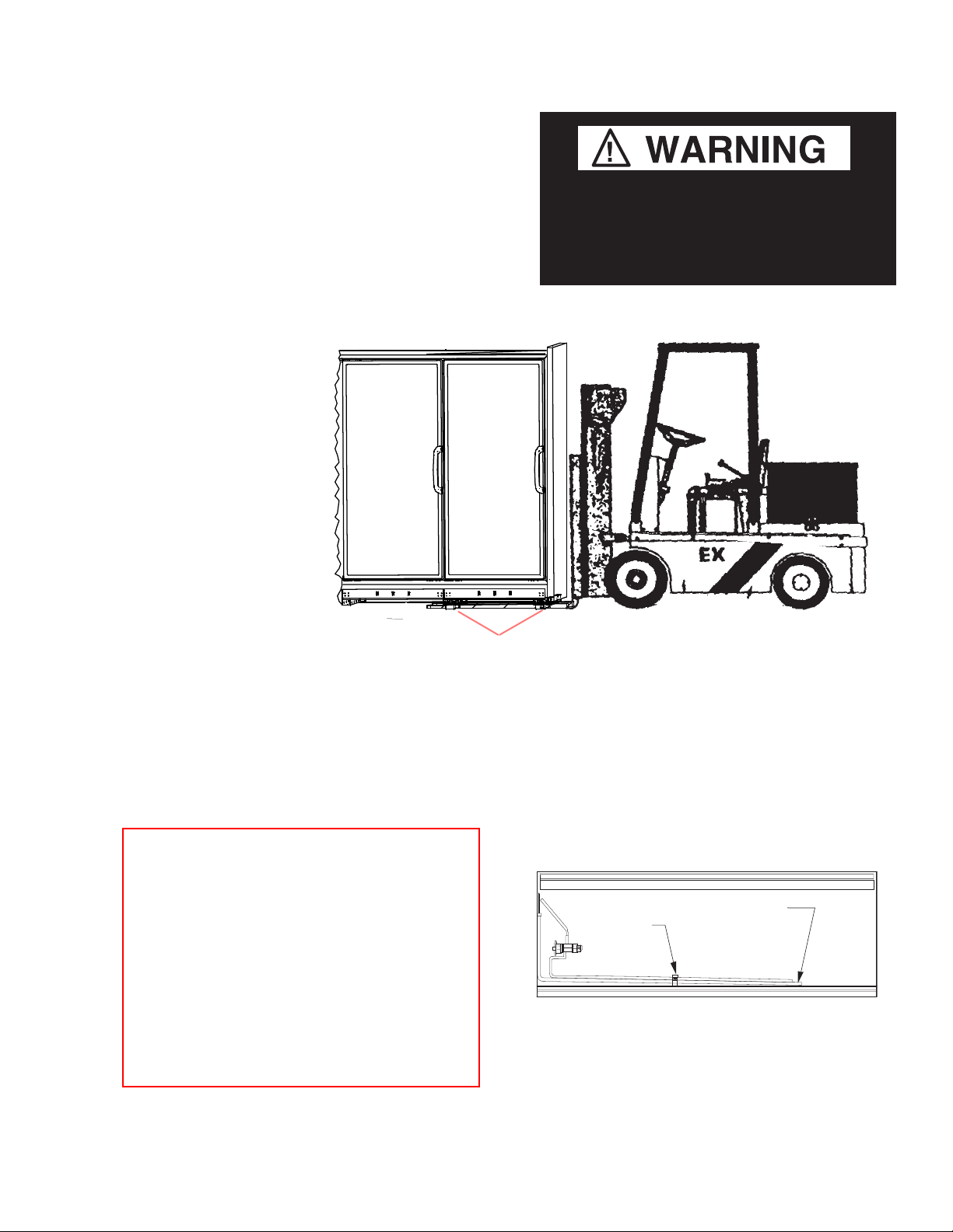
OPTIONAL FORKLIFT POCKETS
Underneath the case there are pockets where
the forks of a forklift can be inserted to move
the case into the store. Ensure forks are inserted
through all four pockets prior to moving the
merchandiser. These shipping pockets (if ordered with the case(s)) can be used to bring the
Ensure the forks are inserted all the way
through all four pockets before lifting the
case. Case tipping could cause personal
injury and / or damage to the equipment.
merchandiser into the store and place it to its
nal location.
Optional Fork
SHIPPING BRACES
Lift Pockets
Move the merchandiser as close as possible
to its permanent location and then remove all
packaging. Check for damage before discarding
packaging. Remove all separately packed accessories such as kits and shelves.
Locate the shipping block in the center of the
heat exchanger (see illustration), and remove it
before piping the merchandiser. This block was
installed to minimize shipping vibration.
Remove the bottom display pans and air return
grilles from the case(s).
Shipping
Block
Top View of Merchandiser
Heat Exchanger
Front Shipping Brace
HUSSMANN CORPORATION • BRIDGETON, MO 63044-2483 U.S.A. Freedom Line Reach-in
Page 8

1-4 InstallatIon
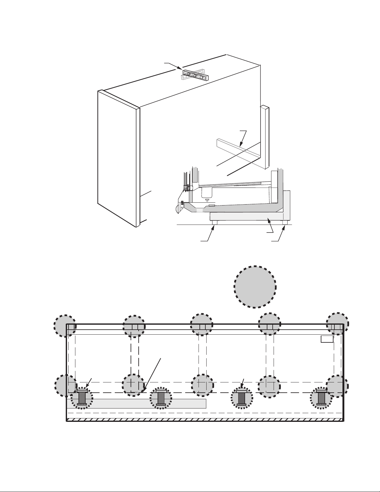
LEVELING
Merchandisers must be installed level to ensure proper operation of the refrigeration
system and to ensure proper drainage of
defrost water. When leveling merchandisers,
use a carpenter’s level as shown.
Metal leveling shims or wedges are provided
with each merchandiser for use if needed.
NOTE:
hI g hest p oInt o f the stor e floo r .
Be g In lI n eup l evelI n g fro m the
Place shims under the rail and make sure
that they are positioned at a base component
(crossbar). This transfers the weight directly
from the loaded case through to the oor.
See illustrations on next page
Placing shims at other locations will cause
uneven distribution of weight leading to
piping leaks, as well as sagging or wracked
doors.
Case Leveling
Shim Case
P/N 0539221_H U.S. & Canada 1-800-922-1919 • Mexico 1-800-890-2900 • WWW.HUSSMANN.COM
Page 9
P/N 0539221_H 1-5
Approximately
Centered
Rear of Reach-In
Base
Component
Base Component
If any of the Earthquake Shoes are not in contact with the floor,
these Earthquake shoe locations must be shimmed, using
provided shims
4-Door Merchandiser Shown
No Gap
between
earthquake
Skid External Base
shoe and the
oor
Shim HereShim Here
Shim
Locations
Earthquake
Shoe
Correct Shim Location is Critical
HUSSMANN CORPORATION • BRIDGETON, MO 63044-2483 U.S.A. Freedom Line Reach-in
Page 10

1-6 InstallatIon
DOOR ADJUSTMENT
After leveling and joining the merchandisers,
adjust and level doors according to manufacturer’s
instructions shipped with each product. Factory
settings may be lost due to vibration during
shipment.
JOINING
Sectional construction means that two or more
merchandisers may be joined in line yielding
one long continuous display requiring only one
pair of ends. Joining kits and instructions are
shipped with each merchandiser.
To join merchandisers with independent ends,
a joining kit is required.
The painted caps for the end assembly bolt holes
may be kept with this manual. Insert two insulating plugs into each bolt hole of the ends to be
joined. After leveling and aligning the top edge
of the ends, install the two case-to-case brackets
on to the top with sheet metal screws as shown
below.
To join unlike xtures, or like xtures operating
at different temperatures, a 2inch (51mm)
partition kit is required. To join same temperature
merchandisers on different defrost cycles, a
plexiglass partition kit is required. Install ‘J’
trim between cases.
all joinTs musT be
air-TighT To prevenT
formaTion of ice
or condensaTion.
Use J-Bar to Align Cases for Joining
Remove Top Panel
Case End Cap
Bolt Hole
Locations
P/N 0539221_H U.S. & Canada 1-800-922-1919 • Mexico 1-800-890-2900 • WWW.HUSSMANN.COM
Page 11
P/N 0539221_H 2-1
REFRIGERATION / ELECTRICAL / SAFE-NET III
REFRIGERANT
The correct type of refrigerant will be stamped
on each merchandiser’s serial plate. The serial
plage is located on the left-hand end of the
interior top liner.
When brazing pipes be sure to use the
insulation blanket shipped with the
merchandiser to prevent damage to
the plastic case bottom.
Refrigeration lines are under pressure.
Depressurize and recover refrigerant before
attempting any connection or repair.
Refrigerant vapor is hazardous to your health
and can cause death. Avoid breathing refrigerant and lubrication vapor or mist. Exposure
may irritate eyes, nose and throat. If accidental system discharge occurs,ventilate work
area before resuming service.
Always wear safety goggles and protective
gloves when working with refrigerants. Contact
with refrigerant may cause injury. Disconnect
hoses with extreme caution! All hoses may
contain liquid refrigerant under pressure.
Be sure that any room where you are working
is thoroughly ventilated, especially if a leak is
suspected.
Read all safety information regarding the safe
handling of refrigerant and refrigerant oil, including the Material Safety Data Sheet. MSDS
sheets can be obtained from your
refrigerant supplier.
HUSSMANN CORPORATION • BRIDGETON, MO 63044-2483 U.S.A. Freedom Line Reach-in
Page 12
2-2 RefRigeRation/electRical/Safe-net iii
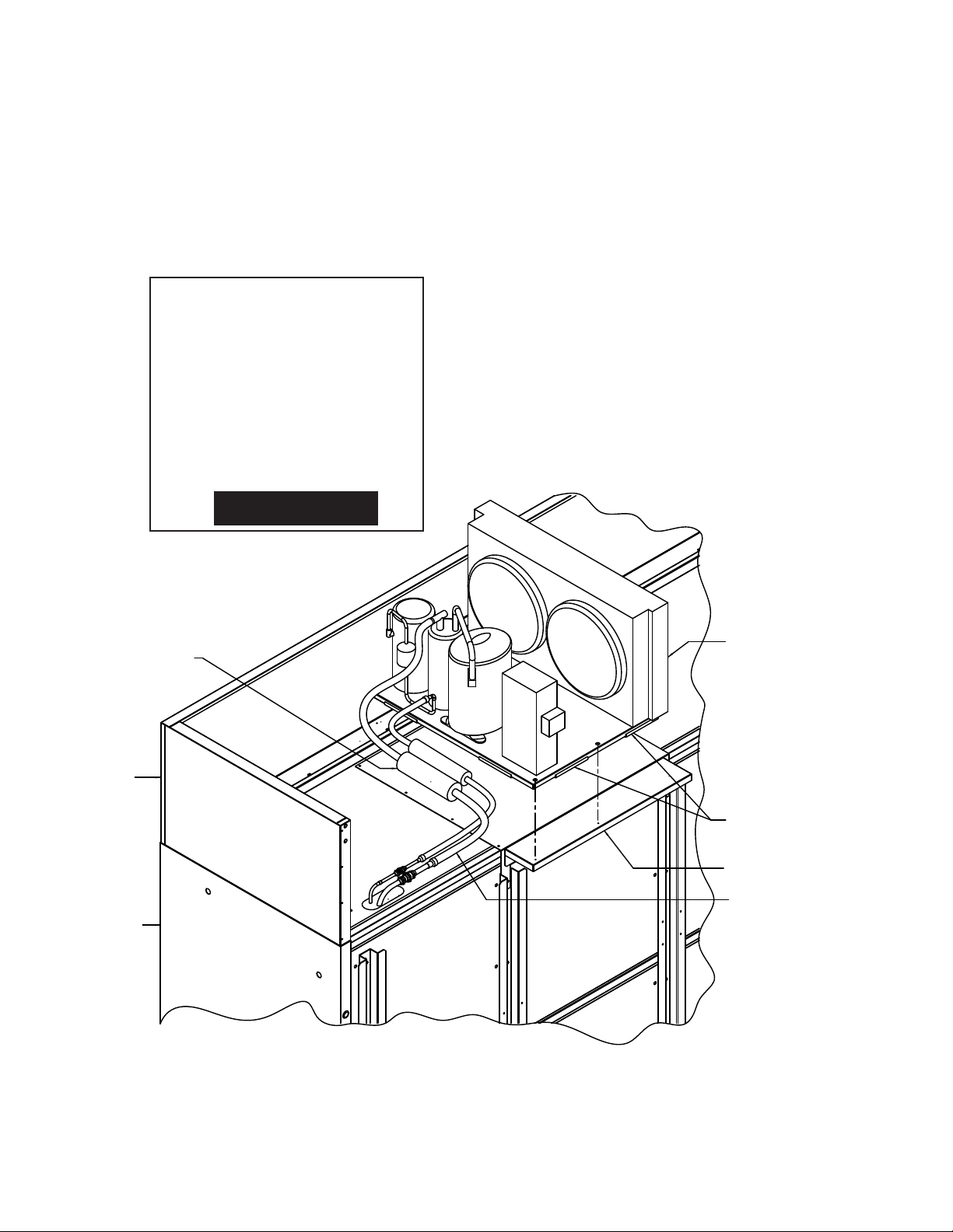
FIELD INSTALLATION OF CONDENSING UNIT
A mounting plate is provided on top of the
case with pilot holes that provide specic
attachment points for the condensing unit
base. The mounting plate is located above the
next to last door on the right.
Condensing Unit
The condensate pan, if selected by the end
user, is packed inside the case and must also
be installed and leveled on top of the case,
then plugged into the 120V GFCI outlet
provided.
Exact component location is not critical;
however, the components should be mounted
in the general locations shown below to ensure that electrical connections reach, and the
condensate pan has adequate air ow from the
condenser.
Insulation Sponge 5/8 inch x 3/4 inch wall
insulation to cover entire length from
Condenser Unit connection to end
of copper tubing, where it enters at
top of case, including quick connects
Facades
Right side of case
looking from the front
Orient the Condenser Unit as shown on top
of the case. Line up mounting holes on base
of condenser unit with holes on mounting
plate and secure using (4) 12-14 x 2 1/4 inch
screws and flat washers
Apply Rubber Gasket along base edges that
contact mounting plate (8) places (2 each
side) as shown
Rear Bracket used on 4 & 5 Door Cases Only.
Sound Panel Kits Use Similar Bracket For 3
Door Cases.
Connect quick connects on flexible liquid &
suction lines from condensing unit to quick
connects on pipes exiting top right of case
5-Door Case & Condenser Unit Shown
P/N 0539221_H
U.S. & Canada 1-800-922-1919 • Mexico 1-800-890-2900 • WWW.HUSSMANN.COM
Page 13
P/N 0539221_H 2-3
The wiring connection for the condensing unit
is provided with 5-ft leads. The conduit must
be connected to the condensing unit electrical box, and the leads are connected to the
condensing unit input terminals. The heated
condensate pan, if provided, is plugged into
the 120V GFCI receptacle at the top of the case.
To avoid serious injury or death from electrical
— LOCK OUT / TAG OUT —
shock, always disconnect the electrical power
at the main disconnect when servicing or
replacing any electrical component. This
includes, but is not limited to, such items as
doors, lights, fans, heaters, and thermostats.
Blocked drain lines will cause water to back up
in the case and spill onto the floor, causing a
slip hazard.
TO TOP OF CASE
CONDENSATE EVAP PAN
DETAIL A
Detail A
COPPER TUBE
Copper Tube Condensate Pan
CONDENSATE PAN
CLAMP 3/8" COPPER TUBE
Clamp 3/8 inch
TO TOP OF CASE
copper tube to top
of case
ATTACH 3/8" TUBING TO
Attach 3/8 inch tubing to condensate
CONDENSATE PAN COPPER TUBE
USE TIE-RAP TO SECURE
pan copper tube use tie-rap to secure
CLAMP 3/8" TUBING
TO TOP OF CASE
Clamp 3/8 inch tubing to top of case
TUBING FROM CONDENSATE
Tubing from Condensate Pump is
PUMP MOUNTED TO BOTTOM OF CASE
mounted to bottom of Case
Condensate Evaporator Pan
A
to knockout
KNOCKOUT IN RACEWAY
Plug Condensate
PLUG CONDENSATE EVAP PAN
Evap Pan into GFCI
INTO GFCI OUTLET AS SHOWN
Outlet as Shown
Connector
in Wireway
CONNECTOR TO
Conduit PVC X-Flex from
Handy Box located at
CONDUIT PVC X-FLEX
FROM HANDY BOX LOCATED
bottom of Case
ON BOTTOM OF CASE
CLAMP CONDUIT PVC X-FLEX
Clamp Conduit PVC
X-Flex to top of Case
CLAMP CONDUIT PVC X-FLEX
Clamp Conduit PVC X-Flex
AND 3/8" TUBING TO REAR
FOAM PANELS AS REQUIRED
and 3/8 Tubing to rear foam
panels as required
Condensate Pan Installation and Location
HUSSMANN CORPORATION • BRIDGETON, MO 63044-2483 U.S.A. Freedom Line Reach-in
Page 14
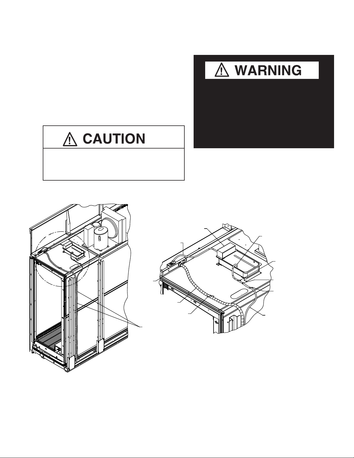
2-4 RefRigeRation/electRical/Safe-net iii
Heated condensate pan
is to be plugged into GFCI
outlet, mounted on top,
EVAPORATOR TO BE
PLUGGED INTO GFCI OUTLET
MOUNTED ON TOP RIGHT SIDE
right side of wireway
OF RACEWAY
Position heated condensate pan to
Dimensions shown and install (4)
POSITION EVAPORATOR TO DIMENSIONS SHOWN
AND INSTALL (4) SM SELF-DRILL SCREWS INTO
SM Self-Drill Screws into Top Foam
TOP FOAM PANEL LINER
Panel Liner
A
View is looking at top of case, right side
Foam Seal must be in place, sealant must
be applied around the copper lines after
Condensate Pan Installation, Location and Electrical
VIEW LOOKING AT TOP OF CASE RH SIDE
connecting the condensing unit.
17 inches
17.00 APPROX.
(432 mm)
(approximate
APPROX.
Detail A
location)
9.00
(229 mm)
9 inches
ABOUT QUICK CONNECT COUPLINGS
Quick Connect ttings are provided on
both the case inlet and outlet lines, and on
Hussmann’s TCL and TCM series of condensing units. The case and condensing unit
are pre-charged with the correct amount of
R404A refrigerant, and the lines are sealed.
Connecting the Quick Connects together
breaks the seals to connect the refrigeration lines of the unit to the case. The Quick
Connects must be properly torqued to avoid
refrigerant leaks.
CONNECT LINES
Mount the suction line and liquid line to the
condensing unit. When ready to connect, remove protector caps and plugs from the Quick
Connect couplings.
If necessary, carefully wipe coupling seats and
threaded surfaces with a clean cloth to prevent
the inclusion of dirt or any foreign material in
the system.
Lubricate male half of diaphragm and
synthetic rubber seal with refrigerant oil.
Thread the coupling halves together by hand
to ensure proper mating of threads. Use
proper size wrenches (on coupling body hex
and on union nut) and tighten until coupling
bodies “bottom” or a denite resistance is felt.
Tighten a ¼ turn after the coupling bottoms
out to ensure a leak proof seal (equivalent to
the foot pounds shown below).
P/N 0539221_H
U.S. & Canada 1-800-922-1919 • Mexico 1-800-890-2900 • WWW.HUSSMANN.COM
Page 15
P/N 0539221_H 2-5
Hex Wrench
Coupling Size
3
/8 in. Male
3
/8 in. Female
5
/8 in. Male 1 1/16 in.
5
/8 in. Female 1 5/16 in.
3
/4 in.
13
/16 in.
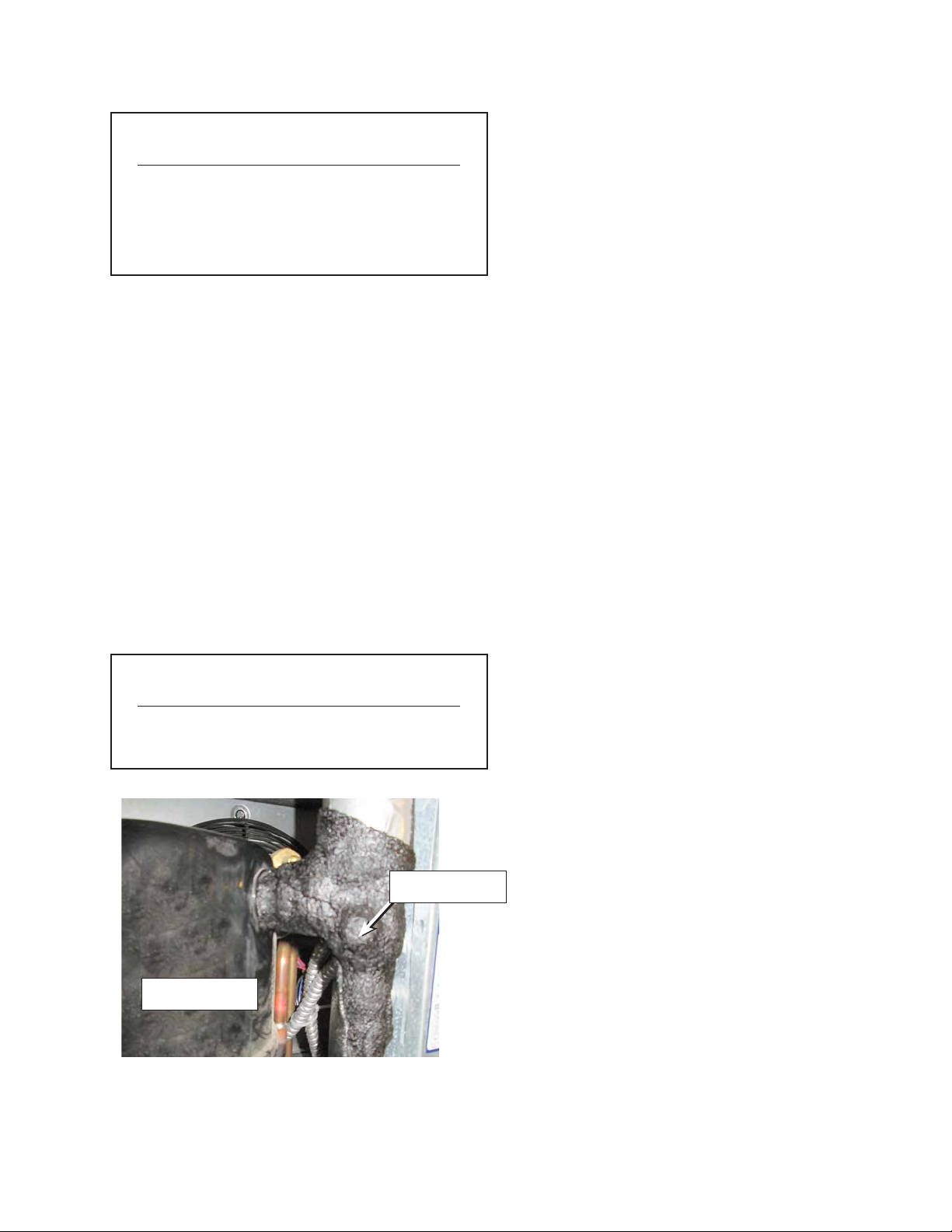
INSULATE REFRIGERANT LINES
Suction lines are insulated to prevent condensation; extra insulation is provided to
cover the eld connected tubing sections.
These exposed sections must be covered with
insulation. Check that all suction lines are
adequately covered with insulation from case
penetration to compressor; including suction
service valves as some insulation may have
been dislodged during shipping and installation. Do not locate the tubing above the
electrical box in order to prevent condensation
from dripping onto electrical components.
FIELD WIRING
All wiring must be in compliance with NEC
and local codes. Field wiring must be sized for
component amperes stamped on the serial plate.
Actual ampere draw may be less than specied.
A conduit whip is provided for the power
input (eld connection) of the 120V single
phase and 208/230V single phase power supply.
The terminal blocks are located inside the
wireway on top of the case. The wiring diagram
and circuit requirements are provided on the
Technical Data Sheets provided with the case
and condensing unit. The disconnect switch
that turns off power to all case components
and the condensing unit is on top of the case,
on the rear of the wireway. When this switch
is off, some electrical terminals in the case
wireway may be energized.
Coupling Foot Pounds
Size (Ft. Lbs.)
3
/8 in. 10-12
5
/8 in. 35-45
Compressor
Insulation
HUSSMANN CORPORATION • BRIDGETON, MO 63044-2483 U.S.A. Freedom Line Reach-in
Page 16
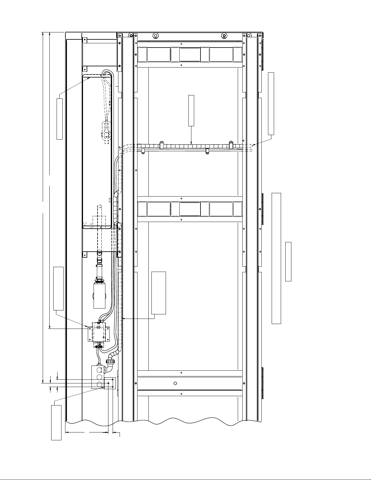
2-6 RefRigeRation/electRical/Safe-net iii
.75
Bottom RH View of Case RFLNS/RFMNS 4 Door
Handy Box Bracket
(Factory Installed)
Factory Installed
Condensate Reservoir
51.83
Conduit and Tubing to top of Case
60.50
Dimensions In Inches
Pump Mounting Bracket
(Factory Installed)
Conduit PVC X-Flex and
3/8 Inch Tubing
(Factory Installed)
1.25
.62
P/N 0539221_H
7.75
U.S. & Canada 1-800-922-1919 • Mexico 1-800-890-2900 • WWW.HUSSMANN.COM
Page 17
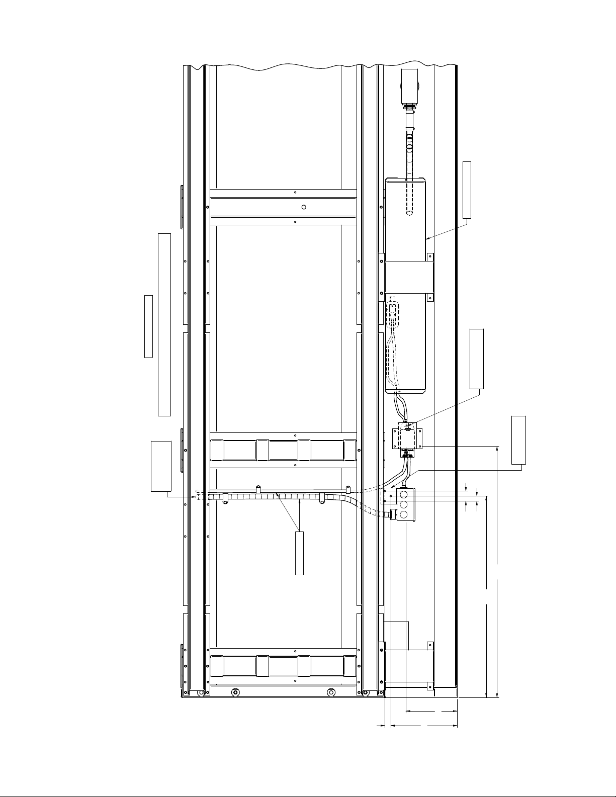
P/N 0539221_H 2-7
Condensate Reservoir
Bottom RH View of Case RFLNS/RFMNS 5 Door
All Dimensions in Inches
Pump Mounting Bracket
(Factory Installed)
(Factory Installed)
at top of Case
Handy Box Bracket
(Factory Installed)
Conduit and Tubing
.62
1.25
Factory Installed
31.42
25.19
6.50
.75
8.32
HUSSMANN CORPORATION • BRIDGETON, MO 63044-2483 U.S.A. Freedom Line Reach-in
Page 18
2-8 RefRigeRation/electRical/Safe-net iii
SAFE-NET III™
TEMPERATURE AND DEFROST
CONTROLLER
SAFE-NET III™ USER INSTRUCTIONS
Your refrigerated case uses a Hussmann
Safe-NET™ III temperature and defrost
controller to precisely maintain the temperature and prevent frost buildup on the cooling
coil. LEDs indicate when the compressor or
refrigeration is on, when the case is in a defrost
cycle, if the temperature is outside the desired
range, or if there is a sensor failure.
An adjustment knob allows the temperature
to be set within the congured range and can
power off the controller and compressor. Your
controller has been custom-congured to provide the best temperature and defrost control
for your chilled or frozen food.
The front of the controller has an adjustment
knob and status LEDs. The back of the
controller has connections for sensors and
switched equipment.
Adjustment
Knob
Compressor Powered On
Temperature or Sensor Alarm
green
Defrost Cycle
yellow
red
Warm
Position
Off
Position
Cold
Position
The Safe-NET III controller includes the
following features and connections.
• Adjustment knob:
Adjusts the temperature setpoint.
Turn adjustment knob to OFF to turn off
refrigeration system. Unplug merchandiser
from power before servicing the unit.
Heater
E72R only
Case
Temperature
Sensor
Compressor
Fan
E72R only
Evaporator
Temperature
Sensor
Sensor and Switch
Common
Defrost
Termination
Switch (optional)
Power
Interface Box and
Copy Card TTL Connector
• Controller LEDs:
Compressor Powered On LED (green):
Lights while the compressor is running
or the refrigeration valve is open.
Defrost Cycle LED (yellow):
Lights while the refrigeration coil is defrosting.
Temperature or Sensor Alarm (red):
Lights if the temperature is too warm
or too cold. Flashes if a sensor fails.
• Audible Temperature Alarm (optional)
See page 2-8 for alarm settings.
• Rear connections:
– Case temperature sensor:
• Typically senses the temperature
of the air in the case.
Used by the controller to determine when
to power on or power off the compressor
or refrigeration.
– Evaporator temperature sensor:
• Senses the temperature of the
refrigeration coil.
Terminates a defrost cycle when
refrigeration coil ice melts.
– Compressor or refrigeration relay:
• Switches on the compressor or
refrigeration valve for cooling.
The evaporator fans remains ON when the
adjustment knob is in the OFF position.
P/N 0539221_H
U.S. & Canada 1-800-922-1919 • Mexico 1-800-890-2900 • WWW.HUSSMANN.COM
Page 19
P/N 0539221_H 2-9
DISPLAY
The display includes three red LEDs and two
digits for temperature, defrost status, and error
codes.
The three display LEDs are red; their behavior
matches the LEDs on the controller.
Compressor
Powered On
Defrost Cycle
Temperature or
Sensor Alarm
START-UP
The OFF Position does not disconnect line
voltage to the input terminal blocks.
1. After the toggle switch is turned on, fans and
lights will energize immediately.
2. After turning on the disconnect switch, wait
for the self check to complete. During the
self check, each LED ashes for one second,
then all LEDs turn on for two seconds. If
the LEDs do not ash, make sure the adjustment knob is not in the Off position.
• After the self check, all LEDs turn off
until the compressor starts. There may be a
delay before the compressor starts. If the red
Temperature or Sensor Alarm LED stays
on after the self check.
• The green Compressor Powered On LED
turns on when the compressor starts.
3. The compressor will continue to run until it
reaches its cut-out temperature (pulldown).
Door and frame anti-sweat heaters will
energize after the evaporator temperature
reaches a stable operating temperature, this
may take 30 minutes or longer.
Product will be degraded and may spoil if
allowed to sit in a non-refrigerated area.
NOTE: Do NOT load product until AFTER
merchandiser operates for 24 hours and reaches
desired operating temperature.
1. The merchandiser temperature displays at
startup. The initial defrost starts twelve hours
later. During defrost, the display shows “df.”
This reading will remain displayed during defrost
and until it times out, even though the refrigeration mode has been initiated. (The green LED
will be lit.)
2. The compressor will start after a 30 second delay
once power is applied.
3. The compressor will continue to run until it
reaches its cut-out temperature (Pulldown).
4. The refrigeration cycle will continue for the next
subsequent scheduled (24-hours) or demand
defrost.
5. The above process will repeat (steps3 and 4)
until the power is interrupted.
6. If power stops, the process will start over at step
1, and the time to subsequent defrost will reset.
7. Medium temperature is the same except for a
60-minute time terminated defrost
HUSSMANN CORPORATION • BRIDGETON, MO 63044-2483 U.S.A. Freedom Line Reach-in
Page 20
2-10 RefRigeRation/electRical/Safe-net iii
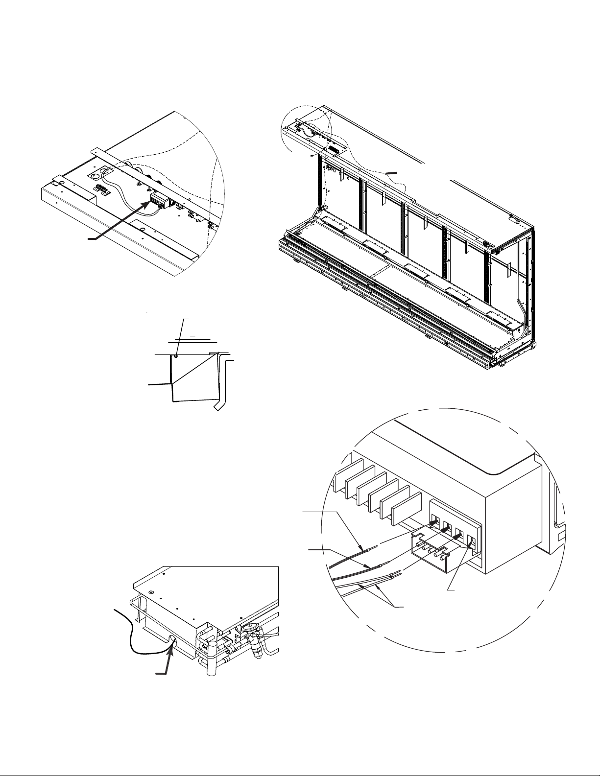
A
White
(Common for
Both Sensors)
#11 Not Used
White
(Common
Both Sensors #10)
Black (Air Sensor #8)
Black (Evaporator Sensor #9)
(Yellow Sheath)
Yellow Sensor: Defrost Termination (Evaporator)
Black Sensor: Control (Air)
Typical Sensor to Control Configuration
Black
(Evap.)
Black
(Air)
Yellow Sheath
(Evaporator Sensor
Defrost Termination)
Black Sheath
(Air Sensor-Display)
A
8
9
10
11
Black
Yellow
A
Safe-NET sensor location
Safe-NET Location
A
A
Safe-NET
Controller
Detail A
Discharge Air Temp Control
Sensor with Tie Strap
Detail B
Safe-NET sensor location
Safe-NET sensor location
Defrost Termination Sensor
located on second return
bend from the front
bend from the front
bottom row as shown
P/N 0539221_H
U.S. & Canada 1-800-922-1919 • Mexico 1-800-890-2900 • WWW.HUSSMANN.COM
Page 21
P/N 0539221_H 2-11
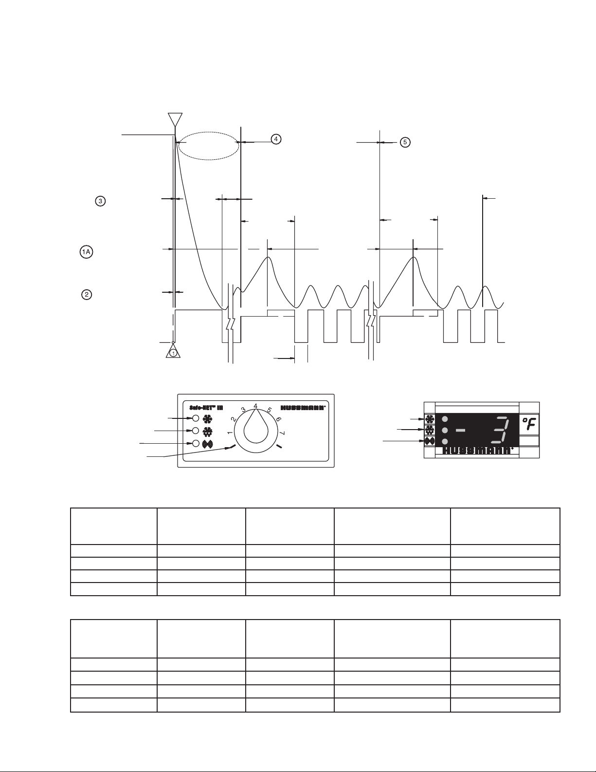
Sequence of Operation
Compressor runs
continuously until it
reaches its cut-out setting.
Defrost cycle is temperature
terminated. Defrost initiates
two hours after start up.
When powered up there will
be a delay of 30 sec. at start
up before the compressor starts.
OFF
Compressor
Starts
Initial Defrost
12 Hours After Start Up
Pull down
Compressor On
Maximum Defrost
Time 45 Minutes
Compressor
Starts
ON
Compressor
Start Up
Off Cycle
RLN
Time to Subsequent Defrost
(6-Hour or Demand Defrost)
Refrigeration Cycle
(Failsafe)
Defrost Cycle
Terminates at
48° F.
Time to Subsequent Defrost
(24-Hour or Demand Defrost)
Maximum Defrost
Time 45 Minutes
(Failsafe)
Pulldown After Defrost
Compressor ON
GREEN (REFRIGERATION)
YELLOW (DEFROST)
RED (ALARM)
“OFF” POSITION
WARM COLD
GREEN (REFRIGERATION)
YELLOW (DEFROST)
RED (ALARM)
DISPLAY
Safe-Net III Controller
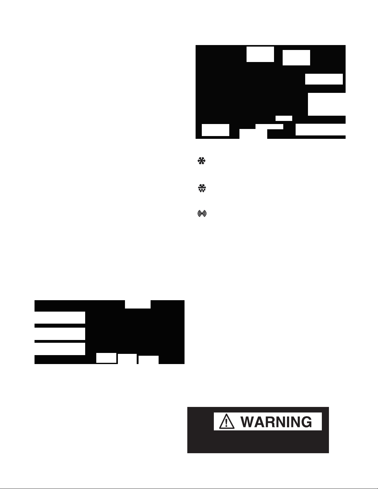
Low Temperature Freedom Safe-NET III Settings
Safe-NET
Dial
Discharge
air Cut-In
Discharge
air Cut-Out
Avg Discharge Air
Temperature
Product Temperature
0 Off
1 0 -6 -2 -5 to 10
4 -8 -14 -6 -11 to 5
7 -17 -23 -14 -18 to 0
Medium Temperature Freedom Safe-NET III Settings
Safe-NET
Dial
Discharge
air Cut-In
Discharge
air Cut-Out
Avg Discharge
air Temperature
Product Temperature
0 Off
1 38 32 36 32 to 42
4 35 29 33 29 to 39
7 33 27 31 27 to 37
Range
Range
HUSSMANN CORPORATION • BRIDGETON, MO 63044-2483 U.S.A. Freedom Line Reach-in
Page 22

2-12 RefRigeRation/electRical/Safe-net iii
TEMPERATURE ADJUSTMENT
Rotate the adjustment knob counter clockwise
for a warmer setpoint or clockwise for a colder
setpoint.
• While the temperature is being adjusted, the
optional display shows the setpoint (cut out
value). A few seconds after the temperature
is set, the display reverts to showing the
sensed temperature in the merchandiser.
ALARMS AND CODES
Flashing TemperaTure or sensor alarm
leD, e1 or e2
Alarm Settings
Low Temperature –7°F to 10°F
Medium Temperature 43°F to 48°F
Alarm settings vary depending on temperature
control setting. The Safe-NET control features
an alarm delay to allow for stocking, pulldown
after defrost, and startup.
MANUAL DEFROST
4
3
2
1
Warm
Note location of
1.
knob setting
4
3
2
1
5
6
7
Cold
5
6
7
Note:
This procedure initiates a
manual or forced
defrost.
If the Temperature or Sensor Alarm LED (red)
on the controller and display is ashing, a
temperature sensor has failed. The display
shows E1 if the case sensor has failed or E2 if
the evaporator sensor has failed.
If the merchandiser sensor fails, refrigeration
will run continuously. Turn off, or repeat a duty
cycle of a few minutes on and a few minutes off.
When the Safe-NET control is powered up, a
two-digit code will be displayed indicating that
the current settings are installed.
Safe-NET Status Code
Low Temperature 68
Medium Temperature 69
Warm
Rotate knob fully
2.
counterclockwise
until it stops (full
warm - “OFF” position)
Warm
3.
After 10 seconds, but
before 20 seconds,
rotate knob fully
clockwise until it
stops (full cold position)
Cold
4
5
3
2
1
6
7
Cold
IMPORTANT: Return the control knob to its
original setting (Step1) once the manual defrost has been initiated.
P/N 0539221_H
U.S. & Canada 1-800-922-1919 • Mexico 1-800-890-2900 • WWW.HUSSMANN.COM
Page 23

P/N 0539221_H 2-13
ELECTRICAL CONNECTIONS
ALWAYS CHECK THE SERIAL PLATE FOR
COMPONENT AMPERES
.
All wiring must be in compliance with NEC
and local codes.
Electric Defrost is standard for low temperature merchandisers and requires temperature
termination. Off Time Defrost is standard for
medium temperature merchandisers and is time
terminated.
MERCHANDISER ELECTRICAL DATA
Merchandiser data sheets for specic models
are shipped with this manual. The data sheets
Terminal block NOT for case-to-case wire
connection.
provide merchandiser electrical data, standard
electrical schematics, parts lists and performance
data. Refer to the merchandiser data sheets and
IDENTIFICATION OF WIRING
merchandiser serial plate for electrical information. Refer to the separate wiring diagrams
shipped with the case for specic information
about the merchandiser and any optional wiring
kits that may have been applied.
Leads for all electrical circuits are identied by
colored plastic bands. These bands correspond
to the color code sticker (shown below) located
inside the merchandiser wireway.
IN STA LLER
It is the contractor’s responsibility to install
merchandiser(s) in accordance with all local
building and health codes.
WIRING COLOR CODE
Leads for all electrical circuits are identied by a colored plastic band: neutral wire for each
circuit has either White insulation or a White plastic sleeve in addition to the color band.
Pink ........... RefRig. theRmoStat low temP. oRange oR
light Blue . RefRig. theRmoStat noRm temP. tan..........lightS
DaRk Blue . DefRoSt teRm. theRmoStat maRoon ...RecePtacleS
PuRPle ....... anti-Sweat heateRS Yellow* ..DefRoSt heateRS, 120V
BRown .......fan motoRS ReD* ........DefRoSt heateRS, 208V
gReen* ....... gRounD
*eitheR coloReD SleeVe oR coloReD inSulation
ELECTRICIAN NOTE: Use copper conductor wire only.
CASE MUST BE GROUNDED
theSe aRe maRkeR coloRS wiReS maY VaRY.
HUSSMANN CORPORATION • BRIDGETON, MO 63044-2483 U.S.A. Freedom Line Reach-in
Page 24

2-14 RefRigeRation/electRical/Safe-net iii
CONTROLS and ADJUSTMENTS
Refrigeration
Controls
Model
RFLNS
RFLNS
RFMNS
Product
Application
Frozen Food
Ice Cream
Medium Temp.
(Dairy, Deli)
Discharge Air
Temperature
-5° F
-12° F
32° F
1. The Safe-NET III Controller controls refrigeration temperature. This is factory installed in
the control panel. Adjust this control knob to
maintain the discharge air temperature shown.
Measure discharge air temperatures at the
center of the honeycomb.
Defrost
Frequency
(per day)
1
1
1
Defrost Controls
Type of
Defrost
Electric
Electric
O Time
Termination
Temperature
48°F
48°F
NA
Failsafe
Time
(Minutes)
45
45
60
For low temperature models, defrosts are time
initiated and temperature terminated. The defrost setting is factory set as shown.
To ensure a thorough defrost, the defrost must
be terminated by the temperature termination
setting — not by time.
For medium temperature models, defrost is
time initiated and time terminated.
P/N 0539221_H
U.S. & Canada 1-800-922-1919 • Mexico 1-800-890-2900 • WWW.HUSSMANN.COM
Page 25

P/N 0539221_H 3-1
Freedom Line Reach-in
FACADE, SPLASHGUARD AND BUMPERS
INSTALL FACADE
Position facade supports and fasten to top of
case using predrilled holes.
See illustrations on next page.
Install Facade Supports using
holes provided
Fasten end facade to front
facade as shown
HUSSMANN CORPORATION • BRIDGETON, MO 63044-2483 U.S.A. Freedom Line Reach-in
Page 26

3-2 Facade SplaShguard and Bumper
3-2 Facade, SplaShguardS and BumperS
Screw Support
onto Wireway
Cover
Facade Bracket
Detail C
3 Door Facade Shown
(2, 4 & 5 Door)
Use 2 inch Facade Trim for Case
Lineups, fasten into top of case
3 Door Facade Shown
(2, 4 & 5 Door Similar)
C
Facade
Bracket
C
Line up brackets with holes
in wireway cover as shown.
Fasten #8 x 1/2 in HX HD
screws, 4 places each bracket
Wireway Cover
A
Top of Facade to
insert into top part of
Facade Bracket as
shown
P/N 0539221_H
B
Bottom of Facade Panel
to sit into support located
on top of Wireway Cover
U.S. & Canada 1-800-922-1919 • Mexico 1-800-890-2900 • WWW.HUSSMANN.COMU.S. & Canada 1-800-922-1919 • Mexico 1-800-890-2900 • WWW.HUSSMANN.COM
Page 27

P/N 0539221_H 3-3
Freedom Line Reach-in
AIR FLOW BAFFLE
Air ow bafes are required to be installed
between cases to ensure proper air ow circulation of the refrigeration systems. The air ow
bafe should be positioned as shown and are
fastened at the top of the merchandiser using
sheet metal screws.
HUSSMANN CORPORATION • BRIDGETON, MO 63044-2483 U.S.A. Freedom Line Reach-in
Page 28

3-4 Facade SplaShguard and Bumper
1. S lide the splashgua rd support bracket's small flange into the
slots in the bas e rail. T hen slide the splashgua rd retaine r
1. S lide the s plas hguard s upport brack e t's s ma ll flange into the
slots in the bas e rail. T hen slide the s plas hguard retainer
ass e mbly under the ca s e a s shown.
2. R otate the retaine r a s s embly clockwise (from right hand s ide)
while pulling towards the front of the cas e until the forward
most flange s its flush with the ba ck of the color pa ne l.
3. Align the retainer ass embly with a nd a ttach to the s upport
bracket us ing #10 s crews. T hen ins tall a #8 s crew through the
color panel int
o the top retainer flange.
3-4 Facade, SplaShguardS and BumperS
INSTALLING SPLASHGUARDS AND
BRACKETS
The splashguard is shipped inside each
merchandiser.
After merchandisers have
been leveled and joined, and all drip piping,
electrical and refrigeration work has been
completed, re-install the splashguards.
Splashguards are joined with a galvanized
metal splice connector that comes with the
joint kit. Join the splashguards before installing
on case. The leveling brackets have a maximum extension of one(1) inch (25mm) for
uneven oors.
To install splashguards and brackets:
1. Slide the splashguard support bracket’s
small ange into base rail slots. Next, slide the
splashguard retainer assembly under the case
as shown.
2. Rotate the retainer assembly clockwise
(from right hand side) while pulling towards
the front of the case, until the forward most
ange sits ush with the back of the color
panel.
Splashguards Installation
Splashguard
Splice Connector
Side
Detail
3. Align the retainer assembly with and attach
to the support bracket using #10 screws. Then
install a #8 screw through the color panel into
the top retainer ange.
DO NOT
br A ckets .
P/N 0539221_H
plAce shims under splAshguArd
1.
U.S. & Canada 1-800-922-1919 • Mexico 1-800-890-2900 • WWW.HUSSMANN.COM
U.S. & Canada 1-800-922-1919 • Mexico 1-800-890-2900 • WWW.HUSSMANN.COM
2.
3.
Page 29

P/N 0539221_H 3-5
Freedom Line Reach-in
SEALING SPLASHGUARD TO FLOOR
if required by local sanitation codes, or if
desired by the customer, plastic splashguards
may be sealed to the floor using silicone type
sealer. The amount needed will depend on how
much the floor is out of level.
• Remove all dirt, wax and grease from the area
of the splashguard where adhesion will be
necessary. This is to ensure a good, secure
installation.
• Apply a good silicone type sealer along the
bottom of the splashguard. Sealant must be
removed and replaced when servicing.
OptiOnAl stainless steel splashguards may be
sealed to the floor using a vinyl cove base trim.
The size of trim needed will depend on how
much the floor is out of level.
To install the trim to the splashguard:
• Remove all dirt, wax and grease from the
area of the splashguard where adhesion will be
necessary. This is to ensure a good and secure
installation.
• Apply a good contact cement to the cove
trim and allow proper drying time according to
the directions supplied with the cement.
• Install the trim to the splashguard so that it
is lying flush with the floor. Do not seal the
trim to the floor.
• If required by local health codes Cove Trim
may be sealed to the floor using a silicone type
sealer. Sealant must be removed and replaced
when servicing.
Splashguard
Silicone-type
Sealer
Splashguard
Cement
Cove Trim
Page 30

3-6 Facade SplaShguard and Bumper
Merchandiser
Joint
Merchandiser
Joint
Internal Joint
Trims
Full Length
Bumpers
Starter
Bumper
INSTALLING BUMPERS
Offsetting the bumpers and top rails helps to
disguise the joint locations, giving the lineup
a smoother look.
Begin at the left end of the line-up. A starter
bumper is factory-installed with end kits. Insert
the internal joint trim, then add the full-length
bumper.
Align each bumper section with its retainer and
push into place, working from the end of the
lineup. Install full length bumpers and internal
joint trims offset across joints. Make sure that
no gaps exist between sections. Continue installing bumpers the length of the line up.
Do NOT install the last bumper sections at this
time. These sections will be installed in the last
step.
Once all except the last section of bumper have
been installed, refrigerate the case line-up for at
least six (6) hours. The last sections of bumper
should be kept inside a refrigerated case or
cooler during this time to allow the bumpers to
contract.
Before installing the last full-length section,
measure the remaining space. Use a miter box
and ne-tooth saw to cut last bumper to length.
Install the last section.
Bumper
P/N 0539221_H
U.S. & Canada 1-800-922-1919 • Mexico 1-800-890-2900 • WWW.HUSSMANN.COM
Miter Box
Remove protective lm from
bumpers once installation is
complete.
Optional end bumpers are
factory-installed.
Page 31

P/N 0539211_H 4-1
START UP / OPERATION
EXPANSION VALVE ADJUSTMENT
Expansion valves must be adjusted to fully feed
the evaporator. Before attempting to adjust
valves, make sure the evaporator is either clear
or only lightly covered with frost, and that the
merchandiser is within 10 deg F (6.5 deg C)
of its expected operating temperature. Adjust
valves as follows:
Attach two sensing probes (either thermocouple or thermistor)
to the evaporator. Position one
under the clamp holding the
expansion valve bulb; securely
tape the other to the coil inlet
line.
”
Some “hunting
of the
expansion valve is normal.
The valve should be adjusted
so that during the hunting the
greatest difference between
the two probes is 3–5degf
(1.7–2.8degc). With this ad-
justment, during a portion of
the hunting the temperature difference between the probes will
be less than 3degF (1.7degC)
and at times 0.
Make adjustments of no more
than 1/4 turn for Balanced Port
TEV and 1/2turn at a time
for other valve models. Wait
at least 15 minutes before rechecking the probe temperature
or making further adjustments.
Component Location in
RL / RM / RLN /
RLNI Models
Component Location in RLT
Models
HUSSMANN CORPORATION • BRIDGETON, MO 63044-2483 U.S.A. Freedom Line Reach-inHUSSMANN CORPORATION • BRIDGETON, MO 63044-2483 U.S.A. Freedom Line Reach-in
Page 32

4-2 Start up
4-2 Start up
START UP CHECKLIST
Start up should be performed
only by a qualied technician.
PRIOR TO START UP CHECKLIST
• Is the case connected to a power supply as
specied on the nameplate?
• Is the power on at the breaker panel?
• Are the doors properly torqued? Are they
self closing? Check each door from a fully
open position and from about a 1-inch open
positions.
• Are the evaporator fans plugged in? Do they
rotate freely? (The fans can be inspected by
lifting the deck pans in the bottom of the
cases. Manually rotate each fan to conrm
it is free and visually inspect to conrm that
each fan is plugged into its receptacle.)
• Verify that refrigeration line shutoff valves
are in the back-seated (open) position.
• Check that the Safe-NET control knob is in
the correct position:
Low temperature:
7 for ice cream and 1 for frozen food
Medium temperature:
7 for colder, 1 for warmer
The unit will shut off when the knob is set to 0.
• Once the case is considered ready for start up,
move the main switch.
This main switch is located at the rear of the
wireway on the top, left side of the case.
This toggle switch turns on the power to the
condensing unit, and all case electrical components, including anti-sweat heaters, lights
and fans.
• Check the reading on the Safe-NET III
display; it should be displaying the case temperature. The display is located in the center
of the front of the facade above the doors.
The displayed temperature will show the
merchandiser’s discharge air temperature.
• Listen for any unusual sounds or events. For
example: evaporator fan blade interference,
compressor trip on overload, or high head
due to excessive ambient temperature, circuit
breaker trip, etc.
• Check the fan at each door to ensure all
fans are running. The discharge air output
at the top inside front of the case should be
relatively even across the length of the case
(honeycomb area).
P/N 0539211_H U.S. & Canada 1-800-922-1919 • Mexico 1-800-890-2900 • WWW.HUSSMANN.COM
U.S. & Canada 1-800-922-1919 • Mexico 1-800-890-2900 • WWW.HUSSMANN.COM
Page 33

P/N 0539211_H 4-3
DEFROST
Defrost will occur 12 hours after switching the
disconnect switch to the ON position. Defrost
can be set to any time desired by switching the
unit off, then back on again, 12 hours before
the desired defrost time. “Df” is displayed on
the Safe-NET display during defrost. It will
show the discharge air temperature when the
evaporator coil has returned back to stabilized
operating temperature.
During defrost, the condensate pump will
pump defrost water to the condensate pan
located at the top of the merchandiser. On low
temperature cases, the fans shut off during
defrost, and electric defrost heaters energize to
melt the frost off the evaporator coil. Defrost
terminates when the evaporator coil reaches
approximately 48°F. On medium temperature
cases, the fans runs continuously, there are no
defrost heaters, and defrost is time-terminated
after 60 minutes.
Safe-NET III CONTROL SETTINGS AND
OPERATION
CHECKLIST AFTER 12 HOUR RUN TIME
• Check case temperature.
• Verify that the fans are running. (The fans
will be off if the case is in a defrost cycle.
They will come back on after the completion
of this cycle.)
• Initiate a defrost cycle and ensure the heaters
are working properly. See the Safe-NET III
instructions for how to force a defrost cycle.
Check the amp draw at the terminal block,
located in the front electrical raceway, just
below the right most door of the case.)
• Check the door operation again, to ensure
they close properly once the case is down to
operating temperature.
• Are all inspection plates and covers properly
replaced?
• Inspect for any water accumulation resulting from incorrect or unsealed penetrations
where electrical or other lines pass through
the case insulated walls.
These instructions are written for normal frozen food, ice cream, or medium temperature
• Check that the lights come on when the light
switch is in the on position.
application, and provide optimum settings for
normal store conditions. Refer to the Safe-NET
instructions starting on Page 2-5. There is also a
chart that shows low temp. and medium temp.
Freedom settings.
Another reference is the Safe-NET III Manual
available on the Hussmann website.
• Check that the condensate pump and condensate fan turns on. Condensate pump pumps
water to the condensate pan during defrost
Check to ensure there are no leaks. The pump
will be on for only a few seconds. If pump or
condensing pan does not energize, GFCI may
need to be reset.
• See the merchandiser’s Data Sheet Set for
refrigerant settings and defrost requirements.
Bring merchandisers down to the operating
temperatures listed on the data sheet.
HUSSMANN CORPORATION • BRIDGETON, MO 63044-2483 U.S.A. Freedom Line Reach-inHUSSMANN CORPORATION • BRIDGETON, MO 63044-2483 U.S.A. Freedom Line Reach-in
Page 34

4-4 Start up
4-4 Start up
LOAD LIMITS
Shelf life of perishables will be short if load limit
is violated. at no time should merchan-
disers be stocked beyond the load limits
indicated.
CASE LOAD LIMIT
Do not stock product
past load limits.
STOCKING
Product should NOT be placed in merchandisers until all refrigeration controls have been
adjusted and merchandisers are at proper operating temperature.
All shelves and the lower deck are intended to
display product. Shelf height is adjustable in
one inch increments. Spacing of 12inches is
recommended for most applications. Maximum
load per shelf is 170pounds. Merchandisers
may be ordered with optional “L” shaped wire
shelves. Proper rotation of product during
stocking is necessary to prevent product loss.
Always bring the oldest product to the front
and set the newest to the back.
Air disChArge And return flues must re-
mAin open And free of obstruCtion At All
times to provide proper refrigeration and air
curtain performance. Do not allow product,
packages, signs, etc. to block these grilles. Do
not use non-approved shelving, baskets, display
racks, or any accessory that could hamper air
curtain performance.
Do not prop doors open while stocking. And
keep the doors closed as much as possible to
prevent coil frosting and high merchandiser
temperature.
INSTALLING FDA/NSF REQUIRED
THERMOMETER
The following pages provide the same information that ships with the thermometer. This
requirement does not apply to display
refrigerators intended for bulk produce (refer
Do not store items or ammable
materials atop the unit.
Do not walk on case.
P/N 0539211_H U.S. & Canada 1-800-922-1919 • Mexico 1-800-890-2900 • WWW.HUSSMANN.COM
U.S. & Canada 1-800-922-1919 • Mexico 1-800-890-2900 • WWW.HUSSMANN.COM
to Page 1-1).
Please note that the tape cannot be exposed
after installation.
Page 35

P/N 0539211_H 4-5
This is an NSF-7 &
US FDA Food Code
Required
Thermometer
Thermometer — Hussmann Part TM.491 1251
Hussmann Corporation • 12999 St. Charles Rock Road • Bridgeton, MO 63044-2483
U.S. & Canada 1-800-922-1919 • Mexico 1-800-522-1900 • www.hussmann.com
© 2007 Hussmann Corporation
Suggested Mounting Locations
in Single De ck G la ss Front
Me rchandisers
Package Gua rd,
Fa cing Out
Doub le Stic k Tape
Fle xible Plastic
Fits in Pr ice Ta g
Moldings
Hussmann P/N 0429971_C 10/2007
End Panel
Pric e Ta g
Mo ld ing
Suggested Mounting Locations
in Multi-deck Me rchandisers
HUSSMANN CORPORATION • BRIDGETON, MO 63044-2483 U.S.A. Freedom Line Reach-inHUSSMANN CORPORATION • BRIDGETON, MO 63044-2483 U.S.A. Freedom Line Reach-in
Page 36

4-6 Start up
4-6 Start up
Important – Please read!
Food and Drug Administration (US FDA) Food Code [ http://www.fda.gov/ ]
National Sanitation Foundation (NSF / ANSI) Standard 7 [ http://www.nsf.org/ ]
This thermometer is provided in response to United States
and
Each installation will be different
depending on how the unit is
stocked, shopping patterns in the
department and ambient conditions
of the store. The suggested locations
provided herein are possible
locations. It is the responsibility of
the purchaser / user to determine
the location with the food storage
area of the unit that best meets the
code requirements above.
The thermometer may need to be
moved several times to find the
warmest location. Mounting options
include flexible plsatic for price tag
molding application, magnet
applied to back of flexible plastic for
steel end wall, and double stick
tape. Tape must not be exposed
after installation.
Questions about either code should
be addressed to local agencies or
other appropriate officals.
Keep with merchandiser
or give to store manager.
DO NOT DESTROY.
P/N 0539211_H U.S. & Canada 1-800-922-1919 • Mexico 1-800-890-2900 • WWW.HUSSMANN.COM
U.S. & Canada 1-800-922-1919 • Mexico 1-800-890-2900 • WWW.HUSSMANN.COM
Page 37

P/N 0539211_H 5-1
Freedom Line Reach-in
MAINTENANCE
CARE AND CLEANING
Long life and satisfactory performance of any
equipment is dependent upon the care it receives. To ensure long life, proper sanitation and
minimum maintenance costs, these merchandisers
should be thoroughly cleaned, all debris removed and
the interiors washed down, weekly.
Always*Clear™ Glass
Wipe inside of glass with isopropyl alcohol and
a soft cloth. Allow surface to dry before closing
door. Use of other cleaners or abrasives may
damage the Always*Clear surface, and/or void
the warranty. Refer to manual that ships with
doors..
Exterior Surfaces
The exterior surfaces should be cleaned with a mild
detergent and warm water to protect and maintain
their attractive finish.
or scouriNg pads.
Never use abrasive cleaNsers
Do :
• Remove the product and all loose debris to
avoid clogging the waste outlet.
• Store product in a refrigerated area such as
a freezer. Remove only as much product as
can be taken to the freezer in a timely
manner.
• First turn off refrigeration, then disconnect
electrical power.
• Thoroughly clean all surfaces with soap
and hot water. do Not use steam or high
water pressure hoses to wash the
iNterior. These will desTroy The
merchandisers’ sealing causing leaks
and poor performance.
• Remove screws and lift hinged fan plenum
for cleaning.
plenum afTer cleaning merchandiser.
Be sure To reposiTion The fan
Interior Surfaces
The interior surfaces may be cleaned with most
domestic detergents, ammonia based cleaners
and sanitizing solutions with no harm to the
surface.
Do No t U s e :
• Abrasive cleansers and scouring pads, as
these will mar the nish.
• Solvent, oil or acidic based cleaners on any
interior surfaces.
• Ammonia based cleaners on acrylic
surfaces.
Do NOT allow cleaning agent or
cloth to contact food product.
Product will be degraded and may spoil if al-
lowed to sit in a non-refrigerated area.
• Take care to minimize direct contact between fan motors and cleaning or rinse
water.
• Allow merchandisers to dry before
resuming operation.
• After cleaning is completed, turn on power
and refrigerant to the merchandiser.
• Verify that merchandiser is working
properly.
Do NOT use HOT water on COLD glass surfaces.
This can cause the glass to shatter and could
result in personal injury. Allow glass doors to
warm before applying hot water.
Page 38

5-2 Maintenance
Fan Plenum
To facilitate cleaning, the fan plenum is hinged
and also fastened with screws at each end.
After cleaning be sure the plenum is properly
lowered into position and that screws are reinstalled
or producT loss will resulT due to
improper refrigeration.
SHUT FANS OFF
DURING CLEANING
PROCESS.
DRAIN TEE REF
BUSHING-REDUCER 1 1/4 X 1 IN
FITTING-1" MALE THREADED BARBED TUBE ADAPTER
TUBING-PVC CLEAR FLEX ID .750 X 1.000 OD
CLIP JIFFY FOR 3/4 OD
CLAMP HOSE
COVER NOT SHOWN FOR CLARITY
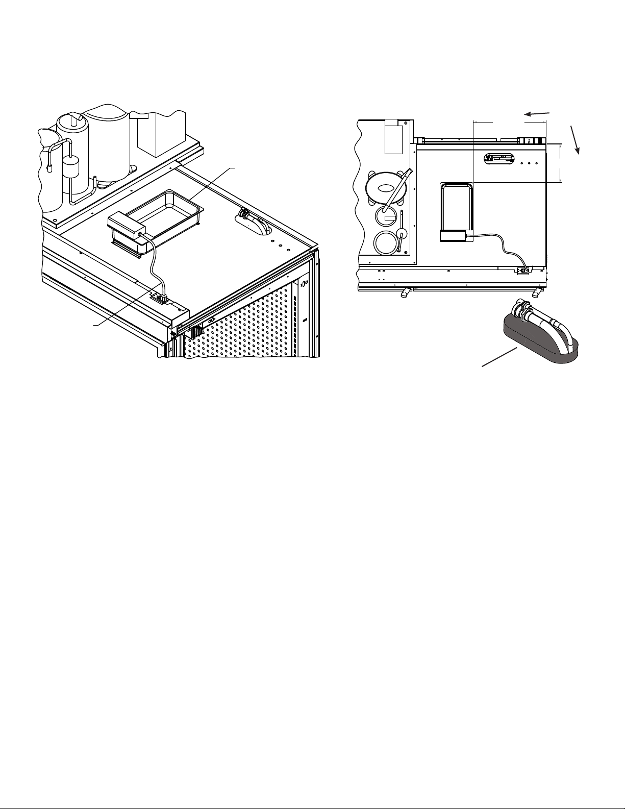
CLEANING CONDENSATE PAN FLOAT
SWITCH
Shut off power. Remove the condensate pan
cover. Remove the bracket that holds the oat
switch in place. Remove the oat switch cover.
Pull out the screen to clean. Also clean inside of
oat switch with warm water. Use warm water
to clean the screen.
CONDENSATE RESERVOIR
PLUG INTO DATA PORT
ON THE PUMP
DETAILA
PAN-CONDENSATE
RESERVOIR
SUMP-UNIT DETECTION
POSITION AS SHOWN WITH VENT
STUB THROUGH THE HOLE IN BRACKET
BRACKET-SUMP
CONNECT SUMP UNIT TO PUMP USING
PROVIDED 0551020 TUBING
SECURE PUMP TO BRACKET
INSTALL PUMP GUARD WITH THE PUMP
SECURE 0543836 TUBING TO
THE OUTPUT OF PUMP USING
A
USING 0551228 SCREW
SEE DETAIL B
CLAMP-HOSE 1/4 TO 5/8
0529081000
PUMP-MAXI ORANGE
BRACKET-HANDY BOX
PLACEMENT ON BACK OF HANDY
BOX DEPENDENT ON WHICH SIDE
PVC CONNECTOR IS MOUNTED
CABLE-ASPEN POWER
COVER-HANDY BOX
0551019
BOX-HANDY
CONNECTOR PVC
ST .375 SNAP
(5 DOOR ONLY)
CONNECTOR
PVC 90 .375 SNAP
(3 & 4 DOOR)
CONDUIT PVC
X-FLEX .375
ROUTEDALONG
BOTTOM
FOAMASSY
AND UP THE
REAR FOAM
PANELS TO
TOP OF CASE
AND INTO
RACEWAY
P/N 0539221_H
U.S. & Canada 1-800-922-1919 • Mexico 1-800-890-2900 • WWW.HUSSMANN.COM
Page 39

P/N 0539211_H 5-3
Freedom Line Reach-in
CLEANING CONDENSATE PUMP AND
HEATED EVAPORATION PANS
always disconnecT power aT The main
case disconnecT Before servicing The
equipmenT.
• The condensate water outlet for the
Freedom case models empties into a limited capacity evaporation pan.
• Clean product spills immediately. If a
product spill enters the Condensate Pump or
Heated Evaporation Pans, a maintenance
technician may be required to clean both the
pump and heated pans.
• Clean case interior with a sponge or soft
cloth, wetted with mild soap and water. Do
not pour water from a bucket or hose into case
drain. Water introduced during cleaning will
cause the evaporation pan to overow.
• If using the optional Defrost
Synchronization controls, the Master Sync
Switch needs to be reset by the maintenance
technician after re-applying electrical power to
case.
— LOCK OUT / TAG OUT —
To avoid serious injury or death from electrical shock, always disconnect the electrical
power at the main disconnect when servicing
or replacing any electrical component. This
includes, but is not limited to, such items as
doors, lights, fans, heaters, and thermostats.
• Sediment and debris will clog the
Condensate Pump and plastic tubing for water
delivery to the Heated Evaporation Pans.
• The Condensate Pump and the Heated
Evaporation Pans require regular monthly
inspection. The Condensate Pump is located
below the case bottom. The Heated Evaporation
Pans are located on the case top. Evidence of
excess water or odor is an indication that immediate service is required.
• Recommended cleaning the Condensate
Pump reservoir and Heated Evaporation Pans
is with mild soap and water. Disconnect power
before cleaning. Empty pump sump and heater
pans of water before reapplying power.
Evaporation Pan is Hot!
and poses risk of bodily injury —
Always wear gloves and protective
eye wear when servicing condensate pump and heated evaporation
pans. Turn off evaporation pan
heater, and allow pan to cool before servicing.
Page 40

5-4 Maintenance
CLEANING HONEYCOMB ASSEMBLIES
Honeycombs should be cleaned every six
months. Dirty honeycombs will cause merchandisers to perform poorly. The honeycombs
may be cleaned with a vacuum cleaner. Soap
and water may be used if all water is removed
from the honeycomb cells before reassembling.
Be careful not to damage the honeycombs.
1. Remove the sheet metal screws located in
the front metal retainer which holds the
honey comb assembly in place.
2. Lift the honeycomb assembly out of the
L-bracket to remove it.
3. Clean and dry the honeycomb.
4. After cleaning, reassemble in reverse order
of removal.
CLEANING STAINLESS STEEL
SURFACES
Use non-abrasive cleaning materials, and always polish with grain of the steel. Use warm
water or add a mild detergent to the water and
apply with a cloth. Always wipe rails dry after
wetting.
CLEANING COILS
NEVER USE SHARP OBJECTS AROUND
COILS. Use a soft brush or vacuum brush to
clean debris from coils. Do not puncture coils!
Do not bend ns. Contact an authorized
service technician if a coil is punctured,
cracked, or otherwise damaged.
ICE in or on the coil indicates the refrigeration
and defrost cycle is not operating properly.
Contact an authorized service technician to
determine the cause of icing, and to make adjustments as necessary. To maintain product
integrity, move all product to a cooler until
the unit has returned to normal operating
temperatures.
CLEANING UNDER MERCHANDISERS
Remove splashguards not sealed to oor. Use
a vacuum with a long wand attachment to remove accumulated dust and debris from under
the merchandiser.
REMOVING SCRATCHES FROM BUMPER
Use alkaline chlorinated or non-chlorine
containing cleaners such as window cleaners
and mild detergents. Do not use cleaners
containing salts as this may cause pitting and
rusting of the stainless steel nish. Do not use
bleach.
Clean frequently to avoid build-up of hard,
stubborn stains. A stainless steel cleaning
solution may be used periodically to minimize
scratching and remove stains. Rinse and wipe
dry immediately after cleaning. Never use hydrochloric acid (muratic acid) on stainless steel.
P/N 0539221_H
U.S. & Canada 1-800-922-1919 • Mexico 1-800-890-2900 • WWW.HUSSMANN.COM
Most scratches and dings can be removed
using the following procedure.
1. Use steel wool to smooth out the surface
area of the bumper or top rail.
2. Clean area.
3. Apply vinyl or car wax and polish surface
for a smooth glossy nish.
Page 41

P/N 0539211_H 5-5
Freedom Line Reach-in
Mimimum Suggested Cleaning and Maintenance Frequency
with Separate TOP-MOUNTED Condensing Unit*
Average Total
Type of Maintenance Maintenance Estimated
Case Scheduled Frequency Duration Maintenance
Component Maintenance (Times / Year)* (hours)* Time/Year (hours)
Evaporator Coil / Case Interior
Honeycomb
Return Air Grille
Drip Piping
Condenser Coil
Condensate Evaporation
Pan
Condensate Evaporation
Pan Heater
Condensate Pump
Compressor
Electromechanical
Thermostats
Compressor Power Relays
Cleaning
Cleaning
Cleaning
Cleaning
Cleaning
Cleaning
None
Cleaning
None
Replacement
Replacement
1
1
12
6
4
4
N/A
6
N/A
0.2
0.2
2
0.05
0.1
0.1
0.1
0.2
N/A
0.05
N/A
1
1
2
0.05
1.2
0.6
0.4
0.8
N/A
0.03
N/A
0.2
0.2
*This table is provided for reference only. The suggested maintenance frequency is
the minimum required to reduce unexpected equipment failure. Performance and
efciency may be enhanced with more frequent cleaning. Individual cleaning
schedules must take into account local environment and usage, as well as all
applicable health codes.
Page 42

5-6 Maintenance
NOTES:
P/N 0539221_H
U.S. & Canada 1-800-922-1919 • Mexico 1-800-890-2900 • WWW.HUSSMANN.COM
Page 43

P/N 0539211_H 6-1
Freedom Line Reach-in
SERVICE
REPLACING FAN MOTORS AND BLADES
For access to these fans:
Always disconnect the electrical power
1. Turn off power.
2. Remove bottom display pans.
3. Disconnect fan from wiring harness.
4. Remove fan blade.
5. Lift fan plenum and remove screws holding
bottom of motor to fan basket.
6. Replace fan motor and blade.
at the main disconnect when servicing or
replacing any electrical component. This
includes, but is not limited to, such items
as fans, heaters, thermostats and lights.
Service
# MO.XXXXXXX
7. Lower fan plenum.
8. Reconnect fan to wiring harness.
9. Turn on power.
10. Verify that motor is working and blade is
turning in the correct direction.
11. Close air gaps under fan plenum. Warmer
air moving into refrigerated air reduces
effective cooling. If the plenum does not
rest against the case bottom without gaps,
apply foam tape to the bottom of the fan
plenum to reduce improper air movement.
Use silicone sealant to close other gaps.
12. Replace display pans. Bring merchandiser
to operating temperature before
restocking.
XXXXXXX
HUSSMANN CORPORATION • BRIDGETON, MO 63044-2483 U.S.A.
Hussmann recommends against frame heater
cycling with Innovator doors to prevent door
seals from freezing to the frames and tearing.
Page 44

6-2 Service
Product will be degraded and may spoil if
allowed to sit in a non-refrigerated area.
REPLACING ELECTRIC DEFROST
HEATERS
Electric defrost requires a heater on the front
and rear of the coil as shown. The heaters are
held in place by tabs in the coil brackets.
Front Defrost Heater
1. Disconnect power.
2. Lift fan plenum up and back to access the
heater.
3. Bend tabs holding heater to horizontal.
4. Remove heater from coil bracket.
Electric Defrost
Bend Tabs
on Each
Bracket
to Release
or Secure
Heaters
5. Position new heater in bracket.
6. Bend tabs back to vertical to hold heater in
bracket.
7. Replace the coil cover and lower fan plenum.
8. Turn on power.
9. Verify that heater is working correctly.
10. Close air gaps under fan plenum. Warmer
air moving into refrigerated air reduces
effective cooling. If the plenum does not
rest against the case bottom without gaps,
apply foam tape to the bottom of the fan
plenum to reduce improper air movement.
Use silicone sealant to close other gaps.
11. Replace display pans. Bring merchandiser
to operating temperature before
restocking.
Rear Defrost Heater
1. Disconnect Power.
2. Remove coil cover.
3. Remove clips holding heater to coil tube.
4. Remove heater from slots in coil bracket.
5. Position new heater in slots.
6. Replace clips.
7. Replace the coil cover.
8. Turn on power.
9. Verify that heater is working correctly.
10. Replace display pans. Bring merchandiser
to operating temperature before
restocking.
Single heater secured at both front
and back of coil
P/N 0539211_H U.S. & Canada 1-800-922-1919 • Mexico 1-800-890-2900 • WWW.HUSSMANN.COM
Page 45

P/N 0539211_H 6-3
Freedom Line Reach-in
REPLACING DRAIN PAN HEATER —
ELECTRIC AND GAS DEFROST
(Low Temperature Only )
The drain pan heater is located as shown below.
Remove Drain Pan Heater
1. Disconnect power.
2. Pull heater out from under jiffy clips.
3. Position new heater under jiffy clips. Be
sure offset is properly positioned around
the drain. If jiffy clips are removed, make
certain sealer is replaced.
4. Reconnect power.
5. Verify that heater is working correctly.
REPLACING DAMAGED DRAIN FITTING
(OPTIONAL)
The following procedure is for the eld repair
of a broken drain tting.
1. Use a drill with a 17/8-inch (48 mm) hole saw
to drill out the bottom of the drain tting. Be
sure to drill completely through tting and bottom liner.
Drain Fitting Viewed from Inside Case
2. Insert adapter into drain tting. Do NOT use
thread sealer on ABS drain tting. If sealer is used the
ABS drain tting may crack or leak! (Tee should be
tightened no more than 4 turns.) Do not overtighten
threads.
Do NOT use Thread Sealer on Drain Fitting!
End Section View
Page 46

6-4 Service
REPAIRING ALUMINUM COIL
The aluminum coils used in Hussmann
merchandisers may be easily repaired in the
eld. Materials are available from local
refrigeration wholesalers.
Hussmann recommends the following solders
and technique:
Solders
Aladdin Welding Products Inc.
P.O. Box 7188
1300 Burton St.
Grand Rapids, MI 49507
Phone: 1-800-645-3413
Fax: 1-800-645-3414
X-Ergon
1570 E. Northgate
P.O. Box 2102
Irving, TX 75062
Phone: 1-800-527-9916
Technique:
1. Locate Leak.
2. REMOVE ALL PRESSURE.
3. Brush area UNDER HEAT.
4. Use PRESTOLITE TORCH ONLY.
Number6 tip.
5. Maintain separate set of stainless steel
brushes and USE ONLY ON
ALUMINUM.
6. Tin surface around area.
7. Brush tinned surface UNDER HEAT,
thoroughly lling the open pores around
leak.
8. Repair leak. Let aluminum melt solder,
NOT the torch.
NOTE:
Hussmann Aluminum melts at 1125°F (607°C)
Aladdin 3-in-1 rod at 732°F (389°C)
X-Ergon Acid core at 455°F (235°C)
Always disconnect the electrical power
at the main disconnect when servicing or
replacing any electrical component. This
includes, but is not limited to, such items
as fans, heaters, thermostats and lights.
9. Don’t repair for looks. Go for thickness.
10. Perform a leak check.
11. Wash with water.
12. Cover with a good exible sealant.
P/N 0539211_H U.S. & Canada 1-800-922-1919 • Mexico 1-800-890-2900 • WWW.HUSSMANN.COM
Page 47

P/N 0539211_H 7-1
OPTIONAL DRIP PIPING
WASTE OUTLET AND WATER SEAL
Drip piping must be installed for cases without evaporation pans. Drip piping is located
between the front merchandiser base and the
splashguard xture and runs parallel to the merchandiser (see Data Sheet for exact locations).
INSTALLING DRIP PIPING
Poorly or improperly installed drip pipes can
seriously interfere with the merchandiser’s operation and result in costly maintenance and
product losses. Please follow the recommendations listed below when installing drip pipes to
ensure proper installation.
• Never use drip piping smaller than the
nominal diameter of the pipe or water seal
supplied with the merchandiser.
Splashguard brackets MUST be installed
before piping merchandiser.
• Provide a suitable air break
between ood rim of the
oor drain and outlet of
drip pipe. To meet code on
low base merchandisers, it
may be necessary to install
a eld-supplied drip pipe
reducer. An alternative is
to cut the last section of
drip pipe at an angle.
• When connecting drip piping, the water
seal must be used as part of the drip piping
to prevent air leakage or insect entrance.
Never use two water seals in series in any
one drip pipe.
ries will cause an air lock anD
prevent Draining.
Double water seals in se-
• Pitch the drip piping in the direction of
ow. There should be a minimum pitch of
1
/4in. perft (20mm per 1m).
• Avoid long runs of drip piping. Long runs
make it impossible to provide the pitch
necessary for good drainage.
• Prevent drip pipes from freezing sweating
or freezing:
A. Do NOT install drip pipes in contact
with uninsulated suction lines. Suction lines
should be insulated with a non-absorbent
insulation material.
B. Where drip pipes are located in dead air
spaces, such as between merchandisers or
between a merchandiser and a store wall,
provide means to prevent drip pipe from
sweating. External ventilation fans may be
required to prevent sweating.
HUSSMANN CORPORATION • BRIDGETON, MO 63044-2483 U.S.A. Freedom Line Reach-in
Page 48

7-2 OptiOnal Drip piping
Do NOT use Thread Sealer on Drain Fitting!
(Drain Fitting)
Factory Installed (four turns)
Approx.
1
/
2
in. Clearance to Floor
1. Tee is factory-installed. If adjustment is necessary,
tighten factory-installed tee no more than ¼
turn. Do not overtighten threads, or the drain
tting or tee may become damaged.
2. Do NOT use thread sealer on ABS drain tting.
If sealer is used the ABS drain tting may crack
or leak! (If a tee needs to be installed it should be
tightened no more than 4 turns.) Do not overtighten threads.
2. Dry t the supplied
water seal / trap to ensure approximately
1
/2
in. of clearance from the
bottom of the trap to the
oor as shown.
Factory-Installed
Tee Fitting
NOTE: It may be necessary to rotate water
seal (trap) inside the tee a few degrees to ensure clearance at two locations. There must be
clearance 1) between the bottom of the water
seal and the oor, and 2) between the top of
the water seal outlet and the bottom of the
merchandiser. Do not over-rotate or gravity seal
may be compromised. Always rotate trap bottom toward merchandiser support rail.
Rotate Water Seal
towards back of
Merchandiser if required
P/N 0539211_H U.S. & Canada 1-800-922-1919 • Mexico 1-800-890-2900 • WWW.HUSSMANN.COM
Page 49

P/N 0539211_H 7-3
3. Install remaining PVC drain parts using
recommended PVC cleaner, primer and
cement per manufacturer’s recommendations.
4. Thread plug into the adapter until snug but
not to exceed four full rotations.
It is the installing contractor’s responsibility
to consult local agencies for
local code requirements.
5. Installed drip piping may require additional
support depending on the number and location of the hub oor drains. The installer
should always provide adequate support
to all drip piping arrangements to prevent
excess stress on all drip piping components.
The installer must provide additional support when “evac” type waste water systems
are applied.
HUSSMANN CORPORATION • BRIDGETON, MO 63044-2483 U.S.A. Freedom Line Reach-in
Page 50

7-4 OptiOnal Drip piping
The instructions on the following pages detail the
installation and operation of the Electronic
Unit Controller. These instructions are
reprinted with permission from: Emerson
Climate Technologies, Inc.
NOTES:
P/N 0539211_H U.S. & Canada 1-800-922-1919 • Mexico 1-800-890-2900 • WWW.HUSSMANN.COM
Page 51

Application Engineering
BULLETIN
Application Engineering
BULLETIN
AE8-1376 R2
AE8-1376 R2
September 2013
Electronic Unit Controller
TABLE OF CONTENTS
Section Page Section Page
Safety
Safety Instructions ....................................................2
Safety Icon Explanation ...........................................2
Instructions Pertaining to Risk of Electrical Shock,
Fire, or Injury to Persons ..........................................3
Safety Statements ....................................................3
1. Introduction and Features .....................................4
1.1 Technical Specifi cations ..................................5
1.2 Pressure Probe Error Bypass .........................5
1.3 Bump Start ......................................................5
2. Installation and Controller Operation Instructions
2.1 Condensing Unit Installation Instructions ........5
2.2 Controller Display ............................................5
2.3 Button Descriptions and Key Combinations ....6
2.4 Viewing the Set Points ....................................7
2.5 Changing a Parameter Value ..........................7
2.6 Entering the Advanced Options Menu .............7
2.6.1 Moving Parameters Between the
Programming Menu and the Advanced
Options Menu .............................................. 7
2.7 Locking the Keypad ....................................... 7
2.8 Unlocking the Keypad ...................................7
2.9 Resetting the Alarm and Runtime Counters .. 8
3. Alarm Menu ............................................................8
4. Service Menu .........................................................8
5. Parameter List........................................................9
6. Controller Wiring ..................................................10
6.1 Additional Controller Inputs ...........................10
7. Alarms/Notifi cations .............................................11
7.1 Discharge Line Temperature Protection ........12
7.2 UL High Pressure Safety Control ..................12
8. Thermister Temperature Resistance Values ... 13-14
9. Troubleshooting Guide .....................................15-16
© 2013 Emerson Climate Technologies, Inc.
Printed in the U.S.A.
1
Page 52

AE8-1376 R2
Application Engineering
BULLETIN
Safety Instructions
Copeland
Safety Standards. Particular emphasis has been placed on the user's safety. Safey icons are explained below
and safety instructions applicable to the products in this bulletin are grouped on Page 3. These instructions
should be retained throughout the lifetime of the compessor. You are strongly advised to follow these
safety instructions.
™
brand products are manufactured according to the latest U.S. and European
Safety Icon Explanation
DANGER
WARNING
CAUTION
DANGER indicates a hazardous situation which, if not avoided, will result
in death or serious injury.
WARNING indicates a hazardous situation which, if not avoided, could
result in death or serious injury.
CAUTION, used with the safety alert symbol, indicates a hazardous
situation which, if not avoided, could result in minor or moderate injury.
NOTICE
CAUTION
NOTICE is used to address practices not related to personal injury.
CAUTION, without the safety alert symbol, is used to address practices
not related to personal injury.
© 2013 Emerson Climate Technologies, Inc.
Printed in the U.S.A.
2
Page 53

Application Engineering
BULLETIN
Instructions Pertaining to Risk of Electrical Shock, Fire, or Injury to Persons
AE8-1376 R2
WARNING
WARNING
WARNING
ELECTRICAL SHOCK HAZARD
• Disconnect and lock out power before servicing.
• Allow drive components to electrically discharge for a minimum
of two minutes before servicing.
• Use compressor with grounded system only.
• Molded electrical plug must be used in all applications.
• Refer to original equipment wiring diagrams.
•
• Failure to follow these warnings could result in serious personal injury.
PRESSURIZED SYSTEM HAZARD
• System contains refrigerant and oil under pressure.
• Remove refrigerant from both the high and low compressor side before
removing compressor.
•
• Never install a system and leave it unattended when it has no charge,
a holding charge, or with the service valves closed without electrically
locking out the system.
• Use only approved refrigerants and refrigeration oils.
• Personal safety equipment must be used.
• Failure to follow these warnings could result in serious personal injury.
BURN HAZARD
• Do not touch the compressor until it has cooled down.
• Ensure that materials and wiring do not touch high temperature areas of
the compressor.
• Use caution when brazing system components.
• Personal safety equipment must be used.
• Failure to follow these warnings could result in serious personal injury or
property damage.
CAUTION
Safety Statements
• Refrigerant compressors must be employed only for their intended use.
•
install, commission and maintain this equipment.
•
• All valid standards and codes for installing, servicing, and maintaining electrical and
refrigeration equipment must be observed.
© 2013 Emerson Climate Technologies, Inc.
Printed in the U.S.A.
COMPRESSOR HANDLING
• Use the appropriate lifting devices to move compressors.
• Personal safety equipment must be used.
• Failure to follow these warnings could result in personal injury or
property damage.
3
Page 54

Application Engineering
BULLETIN
1. Introduction and Features
The introduction of the Electronic Unit Controller to
Copeland
™
brand condensing units will provide many
benefi ts to the contractor and end-user. It has been
designed specifi cally for demanding refrigeration
applications to ensure precision in installation and
operation. While the Electronic Unit Controller will
replace existing adjustable low pressure controls, fan
cycle switches and other relays, it also has additional
features. These features include bump start (where
applicable), data storage and short cycling protection
(See Figure 3). This controller does NOT replace the
fi xed high pressure control required by UL.
The Electronic Unit Controller can be used on any
condensing unit application with the appropriate
sensors and relays that will be factory installed on
the condensing unit. This document will explain how
Electronic Unit Controllers affects your installation
process and how it can also assist in troubleshooting if
the need arises.
Controllers will be preprogrammed with the proper
settings, resulting in little to no setup time. The unit will
come with an attached label showing how to adjust the
low pressure cut-in and cut out (See Figure 1). There
will also be an additional label on the inside of the
enclosure which will also list all of the factory default
settings for the controller, including those that are not
adjustable (See Figure 2). The inside label will also
include a basic wiring diagram for the controller, basic
Hold 3 Seconds to Enter Menu
(PSI Light Will Flash)
Cycle Through Menu Options
Select Function
Adjust Value
Store Function
Exit Menu
Alarm Description
PoF Key pad locked
Pon Keypad unlocked
P1 Suction probe failure
P2 Condenser probe f ailure
P3 DLT probe failure
dLt DLT temperature alarm
dLL DLT lock alarm
EE Module Failure
Note: After 15 seconds of inactivity the
controller will revert to the default display
08/12
Figure 1
Figure 2
+
+
Alarm Description
HP High pressure trip alarm
High condenser
HA
temperature alarm
High pressure trip
HPL
lock-out alarm
Functions
Low Pressure
Cut-In
Low Pressure
Cut-Out
More infor mation
inside panel
Scan for Electronic Unit
Controller Alarm Code
and Service Information
052-7269-01
AE8-1376 R2
Features Today Dixell
Low Pressure
Control
High Pressure UL
Safety Control
Adjustable Mechanical Switch Suction Pressure T ransducer
Adjustable or Fixed
Mechanical Switch
Fixed Mechanical Switch
Fan Cycling 2 Mechanical Switches Mid Coil Temperature Sensor
Time Delay Timing module Built In
Discharge Line
Protection
Mechanical Thermostat T emperature Sensor
Bump Start Timing Module Built In
Multi-Refrigerant
Approval
2 Adjustable Mechanical
Pressure Switches
Utilize Mid Coil
T emperatur e Sensors
Data Storage Performance Alert* Built In
Short Cycle
Protection
Performance Alert* Built In
Figure 3
*Copeland PerformanceAlert is not replaced by the Electronic Pressure Control. The PerformanceAlert module includes
many features not included in the Electronic Pressure Control, such as locked rotor protection, loss of phase, etc. The
Electronic Pressure Control is able to interface with PerformanceAlert to display error codes in an easy-to-read format.
© 2013 Emerson Climate Technologies, Inc.
Printed in the U.S.A.
4
Page 55

AE8-1376 R2
Application Engineering
BULLETIN
descriptions of what the buttons on the controller does,
the controller part number and the part number for the
pre-loaded program. A phone number to contact and
a website for more information will be available on the
inside label as well.
1.1 Technical Specifi cations
Mounting: Panel mounting in a 71x29mm panel cut-out
Controller IP Rating: IP20
Front Panel IP rating: IP65
Power supply: 208/230Vac ±10%, 50/60Hz
110Vac ±10%, 50/60Hz
Power absorption: 3VA max
Relay outputs:
Compressor Relay: 250VAC, 16A FLA, 96A LRA
Fan Relay 1: 250VAC, 4.9 FLA, 29.4 LRA
Fan Relay 2: 250VAC, 1.9 FLA. 11.4 LRA
Special Note: EUC fan cycling relays are not
approved for use with ECM motors
Data storage: Non-volatile memory (EEPROM).
Rated impulsive voltage: 2500V; Overvoltage Category: II
Factory Installed Operating Range: -40 – 120°F Ambient
Non-Factory Installed Operating Range: -4 to 120°F Ambient
1.2 Pressure Probe Error Bypass
The pressure probe bypass is in place to allow the
controller to run proper during pull down if a system has
been off for a period of time and the suction pressure is
greater than the maximum value the suction transducer
can read (In most cases, 135 PSIG). If this occurs,
the controller will fl ash the maximum value of the
transducer for 15 minutes or until the suction pressure
is pulled down below the maximum transducer value.
The compressor will run continuously during this time
unless the thermostat input or high pressure input are
opened, or if there is a discharge line temperature trip.
If the 15 minutes expires the pressure probe error P1
is signaled and the compressor is switched on and off
cyclically with (default 5 minutes) and (default
5 minutes) period.
1.3 Bump Start
Bump start is an optional feature which can provide
additional fl ooded start protection. The compressor is
turned on for 2 seconds, then turned off for 5 seconds
3 times before the compressor runs normally. This
allows for refrigerant to exit the compressor without the
oil being removed as well.
Bump start is enabled on all transport units, without
the ability to be turned off. On most stationary units,
it is turned off by default, but can be turned on in the
Advanced Options Menu as by changing to Yes.
(See section 2.6).
2. Installation and Controller Operation Instructions
2.1 Condensing Unit Installation Instructions
A condensing unit with an Electronic Unit Controller
will be installed exactly the same as a condensing unit
with mechanical controls. Customer connections will
not change, and in a vast majority of cases, wiring to
the unit will not change as well. See section 6 for more
information. The key difference with an Electronic Unit
Controller is that setpoints are set electronically rather
than mechanically. See section 2.5 for further details.
If the unit keeps shutting down during charging, the low
pressure cut out can be lowered to allow it to run. Be
sure to adjust it back to the proper setting after charging.
2.2 Controller Display
The controller display is shown in Figure 4 below.
Table 1 provides a description of each of the labeled
lights. The controller is defaulted to display the current
suction pressure to three signifi cant digits in pounds
per square inch gage (psig).
Compressor
Alarm
History
Module Restart,
push to reset the
HPL, DLL lock out faults
(cycle power)
© 2013 Emerson Climate Technologies, Inc.
Printed in the U.S.A.
Fan Motor 1
ServiceActive Alarm
Fan Motor 2
Figure 4
5
Units
Page 56

Application Engineering
BULLETIN
Table 1 – LED Descriptions
LED MODE FUNCTION
ON Compressor On
Flashing Anti-short cycle delay enabled
1
2
PSI
PSI
2.3 Button Descriptions and Key Combinations
Table 2 lists the different buttons on the controller (as shown in Figure 4) as well as their
functions. Table 3 lists the different key combinations that are available and their functions.
ON Fan1 On
ON Fan 2 On
ON Pressures displayed in PSIG
Flashing Programming mode
ON Browsing the service menu
Flashing New alarm indication
ON You’re browsing the alarm menu
ON An alarm is occurring
AE8-1376 R2
Table 2 – Button Descriptions
BUTTON DESCRIPTION
Displays set point
In programming mode it confirms an operation.
1) To override the cut-in value push the start function button
(see Figure 4) for 3 seconds. Compressor will then start.
START
(UP)
(DOWN)
SERVICE
Alarm menu
2) If a DLL or HPL lock out condition occurs, to reset depress
the start button (see Figure 4) for 3 seconds two consecutive
times to reset the lock out condition. (If the temperatures or
pressures are exceeding the cut out trip point values, pushing
the start button will not clear the fault)
In programming mode it browses the parameter codes
or increases the displayed value.
In programming mode it browses the parameter codes
or decreases the displayed value.
To enter the service menu. (See Section 4)
To enter the Alarm menu. (See Section 3)
Table 3 – Key Combinations
KEY COMBINATIONS:
To lock & unlock the keyboard interface
+
+
To enter into programming mode.
To return to the suction pressure display.
© 2013 Emerson Climate Technologies, Inc.
Printed in the U.S.A.
6
Page 57

AE8-1376 R2
Application Engineering
BULLETIN
2.4 Viewing the Set Points:
1. Push and immediately release the key: the display will show the “ Cin”
message.
2. Press to see the value;
3. Push and immediatel y release the k ey: the displa y will show the “
message.
4. Press to see the value.
2.5 Changing a parameter value:
To change the parameter’s value, operate as follows:
1. Hol d down the + keys for 3 seconds or until the “PSI” LED starts blinking to
enter the module’s programming menu.
2. Use or to select the required parameter. Press the key to display its value.
3. Use or to change its value.
4. Press to store the new value.
TO EXIT: Press + or wait 15 seconds without pressing a key.
NOTE: the set value is stored even when the procedure is exited by waiting for the time-out to expire.
2.6 Entering the Advanced Options Menu:
The advanced options m enu will be locked 5 m inutes af ter the controller is po wered. If you need
to access this menu after this time, cycle power to the controller.
1. Ent er the Programming mode by pressing the + keys for 3 s econds (th e PSI
LED starts blinking).
2. Rel ease the ke ys, then push again the + keys for at least 7 seconds. The Pr2
label will be displayed immediately followed from the
NOW YOU ARE IN THE ADVANCE OPTIONS MENU.
3. Use or to select the required parameter.
4. Press the key to display its value.
5. Use or to change its value.
6. Press to store the new value.
TO EXIT: Press + or wait 15 seconds without pressing a key.
NOTE1: if no parameter is present in Pr1, after 3 seconds the “noP” message is displayed.
Keep the keys pushed until the Pr2 message is displayed.
NOTE2: the set value is stored even when the procedure is exited by waiting for the time-out to expire.
Ci.n parameter.
Cou ”
2.6.1 Moving Parameters between the Programming Menu and the Advanced Options Menu
While in the advanced options menu, certain parameters will have a (. period) in between the 2
rd
and 3
character, for example
the Advanced Options Menu.
To add or remove a parameter from the programming menu, press the SET + keys
together while the parameter name is on the display in the advanced options menu. The
(.
period) between the 2
To Exit: Press SET + or wait 15 seconds without pressing the keys.
2.7 Locking the Keypad
1. Keep pressed for more than 3 seconds the + keys.
2. The “POF” message will be displayed and the k eyboard will be locked. At this point it will b e
possible only to see the set points.
3. If a key is pressed more than 3 seconds the “POF” message will be displayed.
2.8 Unlocking the Keypad
Keep pressed together for more than 3 seconds the + keys, until the “Pon” message
is displayed.
© 2013 Emerson Climate Technologies, Inc.
Printed in the U.S.A.
nd
and 3rd parameter will either be added or removed.
Ci.n
. These parameters are in the Programming Menu as well as
7
nd
Page 58

AE8-1376 R2
Application Engineering
BULLETIN
rSA
DLT
Loc
rCA
rCH
rFH
n
HP
dLt
LOC
HP
dLt
Loc
StH
StL
StH
StL
CHH
CHL
CHH
CHL
F1H
F1L
F2H
F2L
2.9 Resetting the Alarm and Runtime Counters
See sections 3 and 4 for more information on the Alarm and Service Menus.
The advanced options m enu will be lock ed 5 minutes af ter the controller is power ed. If you need
to reset counters after this time, cycle power to the controller.
1. Enter the Programming mode by pressing th e + keys for 3 seconds (the PSI
LED starts blinking).
2. Release the keys, then push again the + keys for more than 7 seconds . The Pr2
label will be displayed immediately followed from the “
NOW YOU ARE IN THE ADVANCE OPTIONS MENU.
3. Use or to select the required parameter listed below.
r
4. Press the key to display its value.
5. Use Change the
6. Press to store the new value and reset the c ount er
7. Repeat steps 3 to 6 to reset any additional counters
3. Alarm Menu
The controller records in the Alarm menu the total number of activations of the following alarms.
- High Pressure Trips ( up to 999) -
- High DLT temperature alarm ( up to 999) -
- Total number of manual restarts (HPL and dLL) up to 255 -
To see the alarm counters:
– Reset Alarm Counters (HP,
– Reset Compressor Starts Counters
– Reset Compressor Run Hours Counters
– Reset Fan Run Hours Counters
to y.
1. Push and release the
2. The controller shows the
3. Push the key to see the number of high pressure trips.
4. The controller shows the
5. Push the key to see the number of DLT Trips.
6. The controller shows the
7. Push the key to see the number of manual resets.
key.
.
label.
label.
label.
, and
.
)
Cin
”
parameter.
.
4. Service Menu
In the SERVICE menu the following values are stored:
• Number of compressor starts:
Example: If
• Compressor Run Hours:
Example: If
• Fan Motor 1 Run Hours:
• Fan Motor 2 Run Hours:
To see the Service Counters:
1. Push and hold the
2. See the above list for the counter names and meanings.
© 2013 Emerson Climate Technologies, Inc.
Printed in the U.S.A.
=12
= 8 and
= 500: the total number of compressor starts = 12,500
= 500, the total number of compressor run hours is 8,500
key for 3 seconds
(0-999 resolution 1000);
( 0-65; res. 1000)
(0-65; res. 1000)
(0-65; res. 1000)
8
( 0- 999; res. 1);
(0-999; res . 1)
(0-999; res. 1);
(0-999 resolution 1)
Page 59

AE8-1376 R2
Application Engineering
BULLETIN
5. Parameter List
All of the parameters are listed below, along with their descriptions and default values. Depending on the condensing
unit model, some of these values may be different or not applicable.
Table 4 – Parameters
Label Description Default Range
Default Display Value
Current Suction Pressure (PSIG)
Adjustable In Programming Menu
Compressor cut in (PSIG)
Cin
Compressor cut out (PSIG)
CoU
Adjustable From Advanced Options Menu
Outputs delay at start up (seconds) (Only adjustable on single phase scroll units)
odS
Anti-short cycle delay (Minimum time between compressor off then on) (seconds)
AC
Compressor ON time with faulty probe (minutes)
Con
Compressor OFF time with faulty probe (minutes)
CoF
Suction Pressure Transducer Offset (PSI)
P1F
Bump start enabled
b P
Number of activation of DLT alarm in a hour to lock compressor (Units with discharge
nPS
line temperature protection only)
UL safety digital input activation before compressor lock (Units with fixed high
HPn
pressure controls only)
Fan 1 Cut Out (°F) (Fan Cycling Units Only)
SF1
Fan 1 differential (°F) (Fan Cycling Units Only)
HF1
Fan 2 Cut Out (°F) (Fan Cycling Units Only)
SF2
Fan 2 differential (°F) (Fan Cycling Units Only)
HF2
Reset Alarm Counters (HP, DLT, and Loc)
rSA
Reset Compressor Starts Counters
rCA
Reset Compressor Run Hours Counters
rCH
Reset Fan Run Hours Counters (Fan Cycling Units Only)
rFH
Factory Set Definitions
Minimum set point (PSIG)
LS
Maximum set point (PSIG)
US
Minimum time between two compressor starts (minutes)
ono
Number of fans on during probe fault
nFA
Measurement unit for pressure: PSIG, bar, kPA
Unt
Measurement unit for temperature
CF
Bump Start Compressor on time (seconds)
on
Bump Start Compressor off time (seconds)
oFF
Number of cycle during bump start
nub
Compressor stop time for next bump start (hours)
bEn
DLT alarm temperature to stop compressor (°F)
doF
DLT temperature for compressor restart (°F)
don
DLT Stop compressor delay (seconds)
ALd
Minimum time of compressor off with dLL alarm (minutes)
dLF
Cut In for Condenser Temperature/Pressure alarm (°F)
AU2
Cut Out for high Condenser Temperature/Pressure alarm (°F)
AH2
High condenser temperature alarm delay (minutes)
Ad2
Minimum off time after a High Pressure Trip (minutes)
HPF
25
15
2 or 4 2 - 255
6 6 - 900
5 0-255
5 0-255
0 -120 -120
No no - YES
4
5
70 -40 -ÒSF2
10 1 -100
85 SF1 - 230
15 1 - 100
-7 or 5 -7 - US
135 LS -135
0 0 -15
2 0 - 2
PSI PSI, bar, kPA
F ∞C or∞F
2 1 - 15
5 1 - 15
3 1 - 15
4.0 1.0 - 23.5
220 don - 302
170 -58 - doF
0 0 - 255
0 0 - 15
150 AH2 - 230
140 -40 - AU2
0 0 - 255
oU – US
C
S - Cin
L
0
-15; 0 = always
automatic restart
0
-15; 0 = always
automatic restart
0 - 15
© 2013 Emerson Climate Technologies, Inc.
Printed in the U.S.A.
9
Page 60

Application Engineering
BULLETIN
6. Controller Wiring
WARNING
Always disconnect and lockout the power supply before
beginning electrical installations or troubleshooting.
Copeland PerformanceAlert (CPA)
High Voltage
DLT Sensor
Line
Comm. Port
AE8-1376 R2
Electronic Unit Controller
Figure 5 – Wiring Schematic Example for the Electronic Unit Controller with Copeland PerformanceAlert
Suction Pressure Transducer: Use terminal 9 (+5V) for supply, terminal 11 for ground and terminal 12 for signal
Condenser Temperature Sensor: Connect the probe to terminal 11 (ground) and 10
Thermostat input: use terminals 14-17
UL HP input: use terminals 15-17
DLT Sensor: Connect the probe to terminals 16-17
Copeland Performance Alert (CPA) connection: Connect the CPA as shown in the wiring diagram.
For more information on PerformanceAlert, see Application Engineering Bulletin AE8-1347.
Power supply: use terminals 4-5
Compressor: use terminals 1-3
FAN 1: use terminals 6-7
FAN 2: use terminals 1-2
6.1 Additional Controller Inputs
If any other devices are used to control the condensing unit, such as a thermostat or other type device, it will need
to be a dry contact (no voltage) and will need to be connected to terminals 14 and 17. These terminals are located
on the hotkey cable. These two terminals will be connected together by push-on type connectors allowing for ease
of performing the fi nal connection. See Figure 5 for wiring details.
NOTE: If using a controller such as a thermostat with another device such as a pump down solenoid, no
connections to the controller are required.
© 2013 Emerson Climate Technologies, Inc.
Printed in the U.S.A.
10
Page 61

Application Engineering
BULLETIN
PoF
Pon
dLt
dLL
HPL
CPA
C01
C02
C03
C04
C05
C06
C07
C08
C09
C10
C11
7. Alarms/Notifi cations
In the event of an issue, the below codes will fl ash to indicate the alarm condition.
See Section 9, Troubleshooting Guide, for further instruction.
Table 5 – Alarms And Notifications
Code Description
AE8-1376 R2
P
P
PP1
PP2
PP3
HHA
d
d
HHP
H
C
EEE
If a Copeland PerformanceAlert is installed in the unit, any error codes from the PerformanceAlert
will be displayed on the screen of the Dixell controller. This eliminates the need to count light
flashed on the PerformanceAlert itself. For more information on PerformanceAlert, see AE8-
1347.
Code Three Phase Recip Three Phase Scroll Single Phase
C
C
C
C
C
C
Discharge Temperature Trip Discharge Temperature Trip Discharge Temperature Trip
System Trip System Trip System Trip
Short Cycling Short Cycling Short Cycling
Locked Rotor Locked Rotor Locked Rotor
Open Circuit Open Circuit Open Circuit
Missing Phase Missing Phase Open Run
C
C
C
C
C
Welded Contactor Welded Contactor Welded Contactor
Low Voltage Low Voltage Low Voltage
Lost communications Lost communications Lost communications
DLT Sensor Failure DLT Sensor Failure DLT Sensor Failure
Keypad locked
Keypad unlocked
Suction probe failure
Condenser probe failure
DLT probe failure
High condenser temperature alarm
DLT temperature alarm
DLT lock alarm
High pressure trip alarm
High pressure trip lock-out alarm
Copeland PerformanceAlert not connected properly
Module Failure
Table 6 – Copeland PerformanceAlert Error Codes
NA Reverse Phase Open Start
© 2013 Emerson Climate Technologies, Inc.
Printed in the U.S.A.
11
Page 62

AE8-1376 R2
Application Engineering
BULLETIN
7.1 Discharge Line Temperature Protection
Discharge line temperature protection has traditionally
been handled by a mechanical thermostat, which was
always an automatic reset, and other than the system
not running, gave no indication that a trip had occurred
or is occurring. The Electronic Unit Controller uses a
temperature sensor, which allows for more fl exibility in
what the controller can do. If the unit trips, the unit will
display an error code and log that an error has occurred.
In addition, the controller will allow an automatic reset
up to 4 times per hour. On the fourth trip, the controller
will require a manual reset. The parameter can be
changed in the Advanced Options Menu (see section
2.6) to adjust the total number of trips allowed in an
hour before a lockout. If an always automatic reset is
needed, then can be set to 0. The default value
for the discharge line cut-out is 220°F and the cut-in
is 170°F.
7.2 UL High Pressure Safety Control
High pressure control is a UL safety device. As such,
Emerson Climate Technologies condensing units
equipped with the Electronic Unit Controller still come
with the high pressure mechanical control installed on
the unit. The high pressure controls will all be fi xed to
work with the control, and the value of the cut-out will
be determined by the working pressure of the high side
of the condensing unit. This should have no affect on a
customer’s UL requirements.
The high pressure control will break power to the
compressor output relay, which will shut down the
compressor regardless of the program state. This
change will also allow the controller to read the high
pressure control state, and display the appropriate
error codes as needed. In addition, the controller will
allow an automatic reset up to 4 times per hour. On
the fi fth trip, the controller will require a manual reset.
The parameter
Options Menu (See section 2.6) to adjust the total
number of trips allowed in an hour before a lockout. If
an always automatic reset is needed, then should
be set to 0.
can be changed in the Advanced
© 2013 Emerson Climate Technologies, Inc.
Printed in the U.S.A.
12
Page 63

Application Engineering
BULLETIN
8. Thermister Temperature/Resistance Values for Condenser Temperature Sensor
AE8-1376 R2
Deg C Deg F
-50 -58 329.5
-49 -56 310.9
-48 -54 293.5
-47 -53 277.2
-46 -51 262
-45 -49 247.7
-44 -47 234.3
-43 -45 221.7
-42 -44 209.9
-41 -42 198.9
-40 -40 188.5
-39 -38 178.5
-38 -36 169
-37 -35 160.2
-36 -33 151.9
-35 -31 144.1
-34 -29 136.7
-33 -27 129.8
-32 -26 123.3
-31 -24 117.1
-30 -22 111.3
-29 -20 105.7
-28 -18 100.5
-27 -17 95.52
-26 -15 90.84
-25 -13 86.43
-24 -11 82.26
-23 -9 78.33
-22 -8 74.61
-21 -6 71.1
-20 -4 67.77
-19 -2 64.57
-18 0 61.54
-17 1 58.68
-16 3 55.97
-15 5 53.41
-14 7 50.98
-13 9 48.68
-12 10 46.5
-11 12 44.43
-10 14 42.47
-9 16 40.57
Resistance
(kOhms)
Deg C Deg F
-8 18 38.77
-7 19 37.06
-6 21 35.44
-5 23 33.9
-4 25 32.44
-3 27 31.05
-2 28 29.73
-1 30 28.48
0 32 27.28
1 34 26.13
2 36 25.03
3 37 23.99
43923
5 41 22.05
6 43 21.15
7 45 20.3
8 46 19.48
9 48 18.7
10 50 17.96
11 52 17.24
12 54 16.56
13 55 15.9
14 57 15.28
15 59 14.69
16 61 14.12
17 63 13.58
18 64 13.06
19 66 12.56
20 68 12.09
21 70 11.63
22 72 11.2
23 73 10.78
24 75 10.38
25 77 10
26 79 9.632
27 81 9.281
28 82 8.944
29 84 8.622
30 86 8.313
31 88 8.014
32 90 7.728
33 91 7.454
Resistance
(kOhms)
Deg C Deg F
34 93 7.192
35 95 6.94
36 97 6.699
37 99 6.467
38 100 6.245
39 102 6.032
40 104 5.827
41 106 5.629
42 108 5.438
43 109 5.255
44 111 5.08
45 113 4.911
46 115 4.749
47 117 4.593
48 118 4.443
49 120 4.299
50 122 4.16
51 124 4.026
52 126 3.896
53 127 3.771
54 129 3.651
55 131 3.536
56 133 3.425
57 135 3.318
58 136 3.215
59 138 3.116
60 140 3.02
61 142 2.927
62 144 2.838
63 145 2.751
64 147 2.668
65 149 2.588
66 151 2.511
67 153 2.436
68 154 2.364
69 156 2.295
70 158 2.228
71 160 2.163
72 162 2.1
73 163 2.039
74 165 1.98
75 167 1.924
Resistance
(kOhms)
Deg C Deg F
76 169 1.869
77 171 1.816
78 172 1.765
79 174 1.716
80 176 1.668
81 178 1.621
82 180 1.577
83 181 1.533
84 183 1.491
85 185 1.451
86 187 1.411
87 189 1.373
88 190 1.336
89 192 1.3
90 194 1.266
91 196 1.232
92 198 1.2
93 199 1.168
94 201 1.137
95 203 1.108
96 205 1.079
97 207 1.051
98 208 1.024
99 210 0.9984
100 212 0.9731
101 214 0.9489
102 216 0.9246
103 217 0.9014
104 219 0.8789
105 221 0.8572
106 223 0.836
107 225 0.8155
108 226 0.7956
109 228 0.7763
110 230 0.7576
Resistance
(kOhms)
© 2013 Emerson Climate Technologies, Inc.
Printed in the U.S.A.
13
Page 64

Application Engineering
BULLETIN
8.1 Thermister Temperature/Resistance Values for Discharge Temperature Sensor
AE8-1376 R2
Deg C Deg F
-40 -40 2889.60
-35 -31 2087.22
-30 -22 1522.20
-25 -13 1121.44
-20 -4 834.72
-15 5 627.28
-10 14 475.74
-5 23 363.99
0 32 280.82
5 41 218.41
10 50 171.17
15 59 135.14
20 68 107.44
25 77 86.00
30 86 69.28
35 95 56.16
40 104 45.81
45 113 37.58
50 122 30.99
55 131 25.68
60 140 21.40
65 149 17.91
Resistance
(kOhms)
Deg C Deg F
70 158 15.07
75 167 12.73
80 176 10.79
85 185 9.20
90 194 7.87
95 203 6.77
100 212 5.85
105 221 5.09
110 230 4.45
115 239 3.87
120 248 3.35
125 257 2.92
130 266 2.58
135 275 2.28
140 284 2.02
145 293 1.80
150 302 1.59
155 311 1.39
160 320 1.25
165 329 1.12
170 338 1.01
175 347 0.92
180 356 0.83
Resistance
(kOhms)
© 2013 Emerson Climate Technologies, Inc.
Printed in the U.S.A.
14
Page 65

AE8-1376 R2
Application Engineering
BULLETIN
9. Troubleshooting Guide
Display Likely Causes Other Possible Causes
Controller display remains
blank after applying power
Controller displays correctly,
but the green compressor
light is off and the
compressor is not running
Controller displays correctly
and the green compressor
light is on and the
compressor is not running
Controller fl ashes “135” or
“P1”
• Unit power not properly applied - check
for proper applied voltage
• Power cable harness not plugged in
properly or securely into the back of the
controller – check connections
• Jumper cable not plugged in properly or
securely into the back of the controller –
check connections
• Controller is currently above the cut-in
setting – check cut-in and cut-out settings
• Power cable harness not plugged in
properly or securely into the back of the
controller – check connections
• Current system pressure is above 135
PSIG – wait for system to pull down
• Green harness not plugged in properly or
securely into the back of the controller –
check connections
• Cable not connected properly with the
pressure transducer – check connections
• Power cable miswired – inspect
cable, replace if needed
• Electrical assembly miswired –
trace wiring diagrams
• Jumper cable miswired – inspect
cable, replace if needed
• Power cable not wired to
the contactor or compressor
correctly, check wiring
• Power cable miswired – inspect
cable, replace if needed
• Transducer cable miswired –
inspect cable, replace if needed
• Damaged transducer – inspect
transducer, replace if needed
Controller fl ashes “P2” on a
unit with fan cycling
Controller fl ashes “P2” on a
unit without fan cycling after
replacing a controller
Controller fl ashes “P3” on a
unit with DLT
Controller fl ashes “P3” on
a unit without DLT after
replacing a controller
• Green harness not plugged in properly or
securely into the back of the controller –
check connections
• Controller not programmed properly –
check parameters in the advanced menu
• Jumper cable not plugged in properly or
securely into the back of the controller –
check connections
• Controller not programmed properly –
check parameters in the advanced menu
• Transducer cable miswired –
inspect cable, replace if needed
• Check condenser temperature
sensor resistance values against
table in Section 8.
• Jumper cable miswired – inspect
cable, replace if needed
• Faulty DLT temperature sensor
– check the discharge line
temperature sensor resistance
values against table in Section 8.
© 2013 Emerson Climate Technologies, Inc.
Printed in the U.S.A.
15
Page 66

AE8-1376 R2
Application Engineering
BULLETIN
Troubleshooting Guide (continued)
Display Likely Causes Other Possible Causes
Fans not running on a fan
cycling unit and the fan lights
are not on
Fans not running on a fan
cycling unit and the fan lights
are on
Controller fl ashes “HP” at
power-up
Controller fl ashes “HP” or
“HPL”
• Condensing temperature is currently
below the fan cut-in
• Condensing temperature sensor not
properly installed – check installation
• Power cable harness not plugged in
properly or securely into the back of the
controller – check connections
• Jumper cable not plugged in properly or
securely into the back of the controller –
check connections
• High pressure switch is seeing above the
cut-out pressure
• For a replacing an -00 controller, ensure
that the jumper cable is the latest
revision. It should have a blue wire in the
harness. See replacement instructions
for more details.
• System operation causing high discharge
pressures, check system operations
• Transducer cable miswired –
inspect cable, replace if needed
• Faulty temperature sensor check condenser temperature
sensor resistance values against
table in Section 8.
• Power cable miswired – inspect
cable, replace if needed
• Electrical assembly miswired –
trace wiring diagrams
• Jumper cable miswired – inspect
cable, replace if needed
• Faulty fi xed Hp switch – inspect
switch, replace if needed
• Bad high pressure switch, verify
system pressure when the
pressure switch trips.
• See Section 7.2 for more details.
Controller fl ashes “DLT” or
“DLL”
• System operation causing high discharge
line temperatures, check system
operations
• Faulty temperature sensor check DLT sensor values against
table in section 8.
• See Section 7.1 for more details
Controller fl ashing “HPL” or
“DLL”
• System operation causing high discharge
pressures (HPL) or high discharge line
temperatures (DLL) repeatedly, check
system operations
• To clear an “HPL” or “DLL” lockout, you
can hold the Restart button for 3 seconds
twice, or cycle power to the unit. If using
the reset button, the alarm condition will
have to clear (DLT temperature drops or
Hp switch resets), and any minimum off
time will need to complete (5 minutes for
the fi xed Hp switch)
The contents of this publication are presented for informational purposes only and are not to be construed as warranties or guarantees, express or implied, regarding
the products or services described herein or their use or applicability. Emerson Climate Technologies, Inc. and/or its affi liates (collectively "Emerson"), as applicable,
reserve the right to modify the design or specifi cations of such products at any time without notice. Emerson does not assume responsibility for the selection, use or
maintenance of any product. Responsibility for proper selection, use and maintenance of any Emerson product remains solely with the purchaser or end user.
© 2013 Emerson Climate Technologies, Inc.
Printed in the U.S.A.
16
Page 67

To obtain warranty information
or other support, contact your
Hussmann representative.
Please include the model and
serial number of the product.
Hussmann Corporation, Corporate Headquarters: Bridgeton, Missouri, U.S.A. 63044-2483 01 October 2012
Page 68

Hussmann Corporation
12999 St. Charles Rock Road
Bridgeton, MO 63044-2483
www.hussmann.com
 Loading...