

Page 1

Manual
Installation
& Operation
Rev.0208
,R3Combo
/Chino
R3H, R3HTO, R3HA
Hot Top w/ Self Service Heat or Refrig.
R3H, R3HTO, R3HA
Hot Service/Self-Service/ Case
,R3Combo
with Self Service Front
p/n IGFP-R3, R3H, R3P, R3HA-0208
INSTALLATION & OPERATION GUIDE
Page 2

General Instructions
Table of Contents
General Instructions ................................................. 2
Cut & Plan Views ....................................................... 3
Installation ................................................................. 4
LEVELING.............................................................................................................. 4
JOINT TRIM........................................................................................................... 5
Plumbing .................................................................... 5
WASTE OUTLET AND P-TRAP .............................................................................. 5
Refrigeration ............................................................. 5
T-STAT LOCATION.................................................................................................. 6
Electrical .................................................................... 7
WIRING COLOR CODE ......................................................................................... 7
PLEXIGLASS & ACRYLIC CARE .............................................................................. 7
TIPS & TROUBLESHOOTING ................................................................................. 8
User Information ...................................................... 8
STOCKING.............................................................................................................. 8
Hot Section Startup ............................................................................................. 9
Case Specifications ................................................... 10
Schematics ................................................................ 12
Service Top & Refrigerated Front with Single Front Shelf................................ 12
Service Top & Refrigerated Front with Dual Front Shelves .............................. 22
R3 with Refrigerated Rear Storage .................................................................... 32
R3 Combo Hot & Cold Tops, Refrigerated Front ............................................... 33
Hot Top & Hot Front .......................................................................................... 36
Hot Top & Front Self Service Cold ..................................................................... 41
Appendices ................................................................ 51
APPENDIX A. – Temperature Guidelines ............................................................ 51
APPENDIX B. – Application Recommendations.................................................. 51
APPENDIX C. – Field Recommendations -......................................................... 52
APPENDIX D. – Recommendations to user ....................................................... 53
IGFP-R3H, R3HTO, R3HA, R3Combo-0208
THIS BOOKLET CONTAINS INFORMATION ON:
R3H: Hot Service/Refrigerated Self-Service Case
R3HA / R3HATO: Circulating Hot Air Case
R3 Combo: any combination of Hot and/or Cold Service with
Self Service Refrigerated Front
SHIPPING DAMAGE
All equipment should be thoroughly examined for shipping damage before and during unloading.
This equipment has been carefully inspected at our factory and the carrier has assumed responsibility for safe
arrival. If damaged, either apparent or concealed, claim must
be made to the carrier.
APPARENT LOSS OR DAMAGE
If there is an obvious loss or damage, it must be noted on
the freight bill or express receipt and signed by the carrier’s
agent; otherwise, carrier may refuse claim. The carrier will
supply necessary claim forms.
CONCEALED LOSS OR DAMAGE
When loss or damage is not apparent until after equipment
is uncrated, a claim for concealed damage is made. Make
request in writing to carrier for inspection within 15 days,
and retain all packaging. The carrier will supply inspection
report and required claim forms.
SHORTAGES
Check your shipment for any possible shortages of material. If a shortage should exist and is found to be the responsibility of Hussmann Chino, notify Hussmann Chino. I f
such a shortage involves the carrier, notify the carrier imme-
diately, and request an inspection. Hussmann Chino will
acknowledge shortages within ten days from receipt of
equipment.
HUSSMANN CHINO PRODUCT CONTROL
The serial number and shipping date of all equipment has
been recorded in Hussmann’s files for warranty and replacement part purposes. All correspondence pertaining
to warranty or parts ordering must include the serial number of each piece of equipment involved, in order to provide the customer with the correct parts.
Keep this booklet with the case at all times for future reference.
/Chino
A publication of
Hussmann® Chino
13770 Ramona Avenue • Chino, California 91710
(909) 628-8942 FAX
(909) 590-4910
(800) 395-9229
The Hussmann warranty is printed on the back
of this guide.
2
Page 3

Rev.0208
R3HA with Hot Front
Hot Air Top with Hot Front Option
and Dry Rear Storage
Scale = 1/2"
Optional
8" shelf
Optional 12x20 pans
Dry
Rear
Storage
8
1
/
8
"
20 5/8" Griddle
Glow-Ray
T-5
Light
11 1/2"
Heater
T-5
Light
36
3
/
4
"
1
6
5
/
8
"
13
1
/
4
"6
1
/
4
"
6
"
50 3/4"
16
1
/
2
"
26
1
/
2
"
53"
1
12x20 Drop-In Well
3
2
3
/
4
"
G
Cut & Plan Views
1
1
/
4
"
14
5
/
8
"
r
id
d
le
18"
"
0
1
5
2
0
/
8
"
8
/
3
"
8
9
/
3
1
2
"
1
6
Service Hot / Self Service Case
"
5
0
R3H
Scale=1/2"
1
1
3
/
2
"
3
/
8
"
"
3
5
"
8
/
3
6
3
11 1/8"
1
5
1
26
/8"
Water Reservoir
Pan
5
/
8
"
26
1
/4"
8
3
/4"
33 1/8"
Circulated Hot Air Merchandiser
R3HA
8"
8"
DRAIN &
ELEC.
STUB UP
18" X 18"
CASE FRONT
8-2"
(Variable Lengths)
R3
Plan View = 1/4”
REF.
STUB UP
18" X 18"
48"
Electrical Plug
115VAC
3
"
4
/
1
32
Cutout
9
"
"
4
/
1
4
Elec
Elec Box
Water
"
4
/
1
34
Flange
"
2
/
1
10
Variable Cutout (4’,6’,8’)
1
"
1
"
R3TO
Plan view
Page 4

Installation
IGFP-R3H, R3HTO, R3HA, R3Combo-0208
LOCATION
The refrigerated merchandisers have been designed for
use only in air conditioned stores where temperature and
humidity are maintained at or below 75°F and 55% relative humidity. DO NOT allow air conditioning, electric
fans, open doors or windows (etc.) to create air currents
around the merchandiser, as this will impair its correct
operation.
Product temperature should always be maintained at a
constant and proper temperature. This means that from
the time the product is received, through storage, preparation and display, the temperature of the product must
be controlled to maximize life of the product.
UN-CRATING THE STAND
Place the fixture as close to its permanent position as
possible. Remove the top of the crate. Detach the walls
from each other and remove from the skid. Unbolt the
case from the skid. The fixture can now be lifted off the
crate skid. Lift only at base of stand!
EXTERIOR LOADING
These models have not been structurally designed to sup-
port excessive external loading. Do not walk on their
tops; This could cause serious personal injury and damage to the fixture.
GLASS BREAKAGE
MAY OCCUR!
Retighten glass along clamshell
after leveling and first time case
is brought to full operating
temperature!
GLASS ADJUSTMENT
During shipment, the lubricant inside the cylinders may
have settled. This settling may cause excessive or uneven
tension on the glass - to the point of breakage. To avoid
any damage, please follow these three easy steps:
1. Slowly raise and lower each glass section 6 times to
a height of 6 inches.
2. Increase the height to 12 inches, and raise and lower
the glass 6 more times.
3. Finally raise the glass to its full extension, and lower.
These steps should release any settled lubricant within
the cylinders and prevent any stress on the front glass.
SETTING AND JOINING
The sectional construction of these models enable them
to be joined in line to give the effect of one continuous
display. A joint trim kit is supplied with each joint.
LEVELING
IMPORTANT! It is imperative that cases be
leveled from front to back and side to side prior
to joining. A level case is necessary to insure
proper operation, water drainage, and
plexiglass alignment.
NOTE: A. To avoid removing concrete flooring, begin lineup
leveling from the highest point of the store floor.
B. When wedges are involved in a lineup, set them first.
JOINING R3H, R3HA, R3 Combo's
All cases were leveled and joined prior to shipment to
insure the closest possible fit when cases are joined in the
field. When joining, use a carpenters level and shim legs
accordingly. Case must be raised correctly, under legs
where support is best, to prevent damage to case.
1. Check level of floor where cases are to be set.
Determine the highest point of the floor; cases will
be set off this point.
2. Set first case, and adjust legs over the highest part of
the floor so that case is level. Prevent damage – case
must be raised under leg or by use of 2x6 or 2x4 leg
brace. Remove side and back leg braces after case is
set.
3. Set second case as close as possible to the first case,
and level case to the first using the instructions in
step one.
4. Apply masking tape 1/8" in from end of case on
inside and outside rear mullion on both cases to be
joined.
5. Apply liberal bead of case joint sealant (butyl) to
dotted area shown in (Fig.2, #1) of first case. Apply
heavy amount to cover entire shaded area.
DO NOT USE PERMAGUM!
It is the contractor's
responsibility to install
case(s) according to local
construction and health
codes.
6. Slide second case up to first case snugly. Then level
second case to the first case so glass front, bumper
and top are flush.
7. To compress silicone at joint, use two Jurgenson
wood clamps. Make sure case is level from front to
4
Page 5

Rev.0208
back and side to side on inside bulkheads at joint.
8. Attach sections together via a 2 bolts located in the
base of the case. Secure the overhead structure by
bolting the bracket, located inside behind lights.
9. Apply bead of silicone to top of bulkheads and slip
on stainless steel bulkhead cap. Also apply silicone
to seam between overhead light tubes.
10.Use finger to smooth silicone as thin as possible at
masking tape on inside and outside of rear mullion
(apply additional silicone if necessary). Remove tape
applied on line #3.
CORNER WEDGES
Corner wedges are attached via front and rear
camlocks. Use a 7mm allen wrench to turn the locks.
Do not overtighten! Join the top by using a joint
bracket (included in joint kit) with 3/8" bolts.
JOINT TRIM
After cases have been leveled and joined, and refrigeration, electrical, and wasted piping work completed, install
the splashguards. Fasten along the top edge, or center, with
#10 X 3/8" sheet metal screws.
DO NOT SEAL JOINT T RIM T O FLOOR!
Installing R3HTO, R3HATO
All cases were tested at a level state before shipping. When
joining, use a carpenters level and shim enclosing or supporting cabinet accordingly.
1. Make sure the cabinet you are installing the
R3HATO on is level.
2. Wire unit according to local codes.
1. Never use pipe for condensate drains smaller than
the nominal diameter of the pipe or P-trap supplied
with the case.
2. When connecting condensate drains, the P-trap
must be used as part of the condensate drain to
prevent air leakage or insect entrance. Store plumbing system floor drains should be at least 14" off the
center of the case to allow use of the P-trap pipe
section. Never use two water seals in series in any
one line. Double P-traps in series will cause a lock
and prevent draining.
3. Always provide as much down hill slope (“fall”) as
possible; 1/8" per foot is the preferred minimum.
PVC pipe, when used, must be supported to maintain the 1/8" pitch and to prevent warping.
4. Avoid long runs of condensate drains. Long runs
make it impossible to provide the “fall” necessary for
good drainage.
5. Provide a suitable air break between the flood rim of
the floor drain and outlet of condensate drain. 1" is
ideal.
6. Prevent condensate drains from freezing:
a. Do not install condensate drains in contact with
non-insulated suction lines. Suction lines should be
insulated with a nonabsorbent insulation material
such as Armstrong’s Armaflex.
b. Where condensate drains are located in dead air
spaces (between refrigerators or between a
refrigerator and a wall), provide means to prevent
freezing. The water seal should be insulated to
prevent condensation.
Plumbing
WASTE OUTLET AND P-TRAP
The waste outlet is located off the center of the case on
one side allowing drip piping to be run lengthwise under
the fixture. There are 3 drains in each fixture that can be
easily located.
1-1/2",1", & 3/4" P-traps and threaded adapters are supplied with each fixture. The 3 P-traps must be installed to
prevent air leakage and insect entrance into the fixture.
NOTE: PVC-DWV solvent cement is recommended.
Follow the manufacturer’s instructions.
INSTALLING CONDENSATE DRAIN
Poorly or improperly installed condensate drains can seriously interfere with the operation of this refrigerator,
and result in costly maintenance and product losses. Please
follow the recommendations listed below when installing
condensate drains to insure a proper installation:
WATER SUPPLY
Tap water contains more minerals and will contribute to
the mineral residue and buildup which may impair the case's
performance and create undesireable cleaning issues. It is
recommended that a 5 micro particle filter be used to
filter the incoming water supply. Be sure to flush the water line before hooking it up to the filter to prevent blocking the filter.
Refrigeration - R3H, R3HA with refrigerated front
REFRIGERANT TYPE
The standard refrigerant will be R-22 unless otherwise
specified on the customer order. Check the serial plate
on the case for information.
PIPING
The refrigerant line outlets are located under the case.
Locate first the electrical box, the outlets are then on the
same side of the case but at the opposite end. Insulate
5
Page 6

IGFP-R3H, R3HTO, R3HA, R3Combo-0208
T-Stat &
Ballast
(Located in the
same place for
hot and cold)
Rear Storage
T-Stat and
Solenoid inside
Storage Area
Front Coils
controlled by
EPR Valve
under Deck Pan
(Right side)
suction lines to prevent condensation drippage.
REFRIGERATION LINES
LIQUID SUCTION
3/8" O.D. 5/8" O.D.
NOTE: The standard coil is piped at 5/8" (suction); however,
the store tie-in may vary depending on the number of
coils and the draw the case has. Depending on the case
setup, the connecting point in the store may be
5
/8", 7/8", or 11/8". Refer to the particular case you are
hooking up.
Refrigerant lines should be sized as shown on the refrigeration legend furnished by the store.
Install P-traps (oil traps) at the base of all suction line vertical risers.
Pressure drop can rob the system of capacity. To keep the
pressure drop to a minimum, keep refrigerant line run as
short as possible, using the minimum number of elbows.
Where elbows are required, use long radius elbows only.
CONTROL SETTINGS
See the “Case Specs” section of this guidebook for the
appropriate settings for your merchandiser. Maintain these
parameters to achieve near constant product temperatures. Product temperature should be measured first thing
in the morning, after having been refrigerated overnight.
Defrost times should be as follows: OFF CYCLE - Consult the Case Specification Section of this guide for defrost settings. The number of defrosts per day and the
duration of the defrost cycle may be adjusted to meet
conditions present at your location.
ACCESS TO TX VALVES & DRAIN LINES
MECHANICAL - Remove product from end of case. Remove
product racks. Remove refrigeration and drain access panels
(labeled). TX valve (mechanical only) and drain are located
under each access panel at end of the case.
ELECTRONIC - The Electronic Expansion valve master and
slave cylinder(s) are located within the electrical access
panel(s).
ELECTRONIC EXPANSION VALVE (OPTIONAL)
A wide variety of electronic expansion valves and case
controllers can be utilized. Please refer to EEV and controller manufacturers information sheet. Sensors for electronic expansion valves will be installed on the coil inlet,
coil outlet, and in the discharge air. (Some supermarkets
require a 4th sensor in the return air). Case controllers
will be located in the electrical raceway or under the case.
The front Self Service Evaporator has an E.P.R. valve installed to maintain a constant discharge temperature. It is
located in the front at the right side of the case under the
fan plenum near the TX valve.
THERMOSTATIC EXPANSION VALVE LOCATION
This device is located on the same side as the refrigeration stub. A Sporlan balanced port expansion valve model
is furnished as standard equipment, unless otherwise specified by customer.
EXPANSION VALVE ADJUSTMENT
Expansion valves must be adjusted to fully feed the evaporator. Before attempting any adjustments, make sure the
evaporator is either clear or very lightly covered with frost,
and that the fixture is within 10°F of its expected operating temperature.
MEASURING THE OPERATING SUPERHEAT
1. Determine the suction pressure with an accurate
pressure gauge at the evaporator outlet.
2. From a refrigerant pressure temperature chart,
determine the saturation temperature at the
observed suction pressure.
3. Measure the temperature of the suction gas at the
thermostatic remote bulb location.
4. Subtract the saturation temperature obtained in step
No. 2 from the temperature measured in step No. 3.
3. The difference is superheat.
5. Set the superheat for 5°F - 7°F.
Evaporator Pressure Regulator
An Evaporator Pressure Regulator is installed in the front
of the self service section to maintain a constant discharge
temperature. It is located at the front right side of the
case, under the fan plenum near the TX Valve.
Service Case Temperature Control
Temperature control in the upper section of the R3 with
the Service Option is done by means of a thermostat and
suction solenoid valve. This controls both temperature and
humidity,
T-STAT LOCATION
T-Stats are located within the electrical raceway. Refer to
diagram below.
R3H
6
Page 7

Rev.0208
Electrical
WIRING COLOR CODE
REFRIGERATED
GREEN GROUND
PURPLE ANTI-SWEAT
ORANGE LIGHTS
YELLOW RECEPTACLE
RED / BLACK T-STAT /SOLENOID230V
BLACK / WHITE T-STAT / SOLENOID 115V
BROWN FAN MOTORS
HOT
L1 BLACK
L2 ORANGE
L3 BLUE
NEUTRAL WHITE
NOTE: High Leg Connection
Orange Only
CASE MUST BE GROUNDED
NOTE: Refer to label affixed to case to determine the actual
configuration as checked in the “TYPE INSTALLED” boxes.
ELECTRICAL CIRCUIT IDENTIFICATION
Standard lighting for all refrigerated models will be full
length fluorescent lamps located within the case at the
top.
The switch controlling the lights, the plug provided for
digital scale, and the thermometer are located at the rear
of the case mullion.
The receptacle that is provided on the exterior back of
these models is intended for computerized scales with a
five amp maximum load, not for large motors or other
high wattage appliances. It should be wired to a dedicated
circuit.
ELECTRICAL SERVICE RECEPTACLES
(When Applicable)
The receptacles located on the exterior of the merchandiser are intended for scales and lighted displays. They
are not intended nor suitable for large motors or other
external appliances.
BEFORE
SERVICING
Always Disconnect Electrical
Power at the Main Disconnect
when servicing or replacing
any electrical component.
This includes (but not limited to) Fans,
Heaters, Thermostats, and Lights.
FIELD WIRING & SERIAL PLATE AMPERAGE
Field Wiring must be sized for component amperes printed
on the serial plate. Actual ampere draw may be less than
specified. Field wiring from the refrigeration
control panel to the merchandisers is required for refrigeration thermostats. Most component amperes are listed
in the “Case Specs” section, but always check the serial
plate.
Ballasts are located within the access panel that runs the
length of the rear of the case. Refer to diagram below.
Windex
®
or Glass Plus® are the only solutions recommended to be used to clean the non-glare glass. The damage to the glass from improper, caustic solutions is irreparable.
In addition to cleaning the glass with the recommended
product, there are precautions that should be taken when
working and cleaning the inside of the case.
• When cleaning the inside of the cases, we recommend that the glass be fully opened and covered to
prevent solutions from splashing onto the glass and
ruining the coating on the inside.
PLEXIGLASS & ACRYLIC CARE
Improper cleaning not only accelerates the cleaning cycle
but also degrades the quality of this surface. Normal daily
buffing motions can generated static cling attracting dust
to the surface. Incorrect cleaning agents or cleaning cloths
can cause micro scratching of the surface, causing the plastic
to haze over time.
CLEANING
Hussmann recommends using a clean damp chamois, or a
paper towel marked as dust and abrasive free with 210
Plastic Cleaner and Polish available by calling Sumner
Labs at 1-800-542-8656. Hard, rough cloths or paper towels will scratch the acrylic and should not be used.
ANTISTATIC COATINGS
The 210® has proven to be very effective in not only cleaning and polishing the Plexiglass surface, but also providing
antistatic and anti-fog capabilities. This product also seals
pores and provides a protective coating.
CLEANING
PRECAUTIONS
WHEN CLEANING:
Never Use a Cleaning or Sanitizing
Solution that has an OIL BASE
(these will dissolve the butyl
sealants) or AMMONIA BASE (this
will corrode the copper components
of the case)
TO PRESERVE THE ATTRACTIVE FINISH:
Do Use Water and a Mild Detergent for
the Exterior Only!
Do Not Use Abrasives or Steel Wool
Scouring Pads (these will mar the finish)
®
7
Page 8

IGFP-R3H, R3HTO, R3HA, R3Combo-0208
CLEANING GLASS & MIRRORS
Only use a soft cloth and mild glass cleaner for cleaning
any glass or mirrored components. Be sure to rinse and/
or dry completely.
Never use hot water on cold glass surfaces! It
may shatter and cause serious injury! Allow glass
surfaces to warm
REPLACING FLUORESCENT LAMPS
Fluorescent lamps are furnished with a shatterproof protective coating. The same type of lamp with protective
coating must be used if replaced.
ENCAPSULITE
SHATTERPROOF COATING - SA 10645
R
Complies with FDA USDA
R
U
& OSHA Regulations
for replacement call:
1-800-395-9229
Turn switch off then on after replacing bulb
EVAPORATOR FANS
NSF
The evaporator fans are located at the center front of
these merchandisers directly beneath the display pans.
Should fans or blades need servicing, always replace fan blades
with the raised embossed side of the blade TOWARD THE
MOTOR.
COPPER COILS
The copper coils used in Hussmann merchandisers may
be repaired in the field. Materials are available from local
refrigeration wholesalers.
Hussmann recommends using #15 Sil-Fos for repairs.
TIPS & TROUBLESHOOTING
Before calling for service, check the following:
1. Check electrical power supply to the equipment for
connection.
2. Check fixture loading. Overstocking case will affect
its proper operation.
3. If frost is collecting on fixture and/or product, check
that no outside doors or windows are open—
allowing moisture to enter store. These merchandisers were designed for use in stores were temperature & humidity does not exceed 75° F and 55% H.
User Information
Stocking Refrigerated Sections
Improper temperature and lighting will cause serious product loss. Discoloration, dehydration and spoilage can be
controlled with proper use of the equipment and handling
of product. Product temperature should always be maintained at a constant and proper temperature. This means
that from the time the product is received, through storage, preparation and display, the temperature of the product must be controlled to maximize life of the product.
Hussmann cases were not designed to “heat up” or “cool
down” product—but rather to maintain an item’s proper
temperature for maximum shelf life. To achieve the protection required always:
1. Minimize processing time to avoid damaging temperature rise to the product. Product should be at
proper temperature.
2. Keep the air in and around the case area free of
foreign gasses and fumes or food will rapidly deteriorate.
3. Maintain the display merchandisers temperature
controls as outlined in the refrigerator section of
this manual.
4. Do not place any product into these refrigerators
until all controls have been adjusted and they are
operating at the proper temperature. Allow merchandiser to operate a minimum of 6 hours before
stocking with any product.
5. When stocking, never allow the product to extend
beyond the recommended load limit. Air dis-
charge and return air flue must be unobstructed at all times to provide proper refrigeration.
6. Keep the service doors closed (when applicable).
Refrigeration performance will be seriously affected
if left open for a prolonged period of time.
7. Avoid the use of supplemental flood or spot lighting.
Display light intensity has been designed for maximum visibility and product life at the factory. The use
of higher output fluorescent lamps (H.O.andV.H.O.),
will shorten the shelf life of the product.
FOOD HANDLING and HOT FOOD EQUIPMENT
These hot tables are for short-term holding and display of
precooked hot foods. They are not intended to cool or
reheat food. The temperature of the food should be approximately 160°F when first put into the hot table.
These hot tables are best suited when used in a cafeteria
type application where the food is held and served rapidly,
8
Page 9

Rev.0208
within a few hours. Any attempt to use the hot table to
display large amounts of food for long periods of time will
result in dehydrated, overcooked and unsafe food. The quality of food will progressively worsen as the length of time
increases.
The deterioration of product quality is a function of time
and temperature. All products are affected even though
in a gravy or other liquid. They may appear to withstand
the temperature better than “dry” foods such as fried
chicken but this is not necessarily true. ALL foods will
continue to be affected by prolonged exposure to elevated
temperatures.
The following guidelines are provided only as a general
guide for the use of this equipment. The local health agency
for your area can provide specific temperature requirements.
Critical attention must be given to the heat controls for
these hot tables. Both the upper and lower heat controls
must be adjusted to achieve proper food temperatures.
Hot foods should be held at a minimum temperature of at
least 140°F (60°C) according to 1995 FDA Food Code.
However, increasing the temperature too high will also
cause the food to overcook, dry out, lose its flavor, texture and color. Food held for prolonged periods at high
temperatures will also lose some of their nutritional value.
Different foods will require different control settings. The
type of food, the quantities of food and length of time that
it is to remain in the hot table must be considered when
establishing control settings. Therefore, it must be the user’s
responsibility to establish the correct control settings to
maintain the food at the safest, tastiest and most saleable
condition.
Food temperatures can be accurately determined only through the use of food thermometers!
IMPORTANT OPERATION TIPS:
* Preheat case 30 minutes before loading product
using higher settings.
* Never place food directly into warmer. Always use
an inset and pan.
* Never pour water into a dry preheated warmer. This
may damage the unit. Always pour water into
warmer BEFORE preheating. Always use water in
case wells, as it provides even heat and humidity.
* Too much water or too much heat will cause
excessive condensation on the front glass, decreasing visibility.
* Make sure all pans are in the well units no matter the
configuration.
Using thermometer, check product before
*
loading in case (150°-160°).
* Always use warmer in wet operation when warming
thick food items.
* Stir thick foods such as chili, fudge and chowders
often to keep foods uniformly heated and prevent
scorching.
* At start, set wells to "7". After loading, recheck
temperature every 1/2 hour to see that unit is
operating properly. Adjust the thermostat (a higher
number for hotter and a lower number for cooler)
+
to maintain product temperature of 140°F
(60°C.)
minimum. The setting will depend on the type of
product being displayed and how much there is in
the well. Be sure to test product temperature with a
thermometer frequently for good product maintenance.
* Food must always be placed into a display pan over
the well, never directly into the well.
* Food should not be stacked above the top of the
pan. Food above the top of the pan will dry out
rapidly.
* Food juice or gravy should be stirred frequently and
any meats should be basted with the gravy. Stir and
rotate foods as needed. Wipe up spills immediately for eye appeal now, and easier cleaning later.
* Food should be rotated periodically from the
bottom to top.
* If practical, the food should be covered during slack
sale periods to reduce dehydration.
* At end of the day, remove product and let case cool.
Then clean with soap and water (use oven cleaner
on the difficult spots). Polish and clean glass with a
good glass cleaner.
CONTROLS
The controls are located at the rear of the case.
Ballast
R3HATO
Ballast Locations
9
Page 10

R3H, R3HTO Section Startup
OPERATING INSTRUCTIONS
G
r
IGFP-R3H, R3HTO, R3HA, R3Combo-0208
id
d
le
Storage
Griddle
OVERHEAD LIGHTS ON / OFF
TURN
SWITCHES
ON
Check to make sure all lights
come on at start-up.
If they do not contact your
Service Department
POWER
ON / OFF
Control Panel on Rear of Case
Number of controls may vary.
LIGHTS
ON / OFF
Control Panel
Locaton
START-UP
GRIDDLE
INITIAL
SETTING
5
4
3
2
1
430-01-0365 9810
Parts of the case exterior, shelves and
light bulbs become extremely hot when
in use.
USE EXTREME CAUTION!
OVERHEAD HEAT
INITIAL
SETTING
"7"
6
S
t
a
r
t
u
7
p
8
9
10
"5"
OFF
LO HI
2
3
4
6
5
Allow case preheat for 45 minutes prior to loading
NOTE: This equipment is not designed to heat-up or cook food.
Food must be 150° - 160° when put in display.
1. Measure PRODUCT temperature hourly by inserting a food
thermometer into the food. Proper holding temperature is 140°.
2. To change temperature, increase or decrease Overhead Heat
by one number at a time. Adjust the griddle temperature as
necessary. Measure product temperature again in one hour.
Readjust if necessary.
1. Turn all switches and dials to "OFF" position.
2. Allow case to cool before cleaning.
ADJUST TEMPERATURE
SHUTDOWN
10
Page 11

Rev.0208
R3HA, R3HATO Hot Circulation Air Startup and Operation
Main Power
Lights & Fans
Water Fill
Pump
Primer
(Optional)
Control Panel
Humidity
Control
Pilot Lights
Temperature
Control
Startup:
1. Turn the Main Power Switch ON. (This will enable all other switches in the case).
2. Turn Lights & Fans Switch ON.
3. Turn Water Fill System ON. (For 100% DRY Heat leave water system OFF).
4. Press “PUMP PRIME” for approximately 10 seconds (optional) to self-prime the humidity system. The water reservoir (pan)
INSIDE the case should ALWAYS be half full.
5. Turn Humidity Control knob to # 7, “STARTUP”, for maximum humidity conditions - over 7 may cause condensation on the glass.
This control will continually pump water into the water reservoir (pan) INSIDE the case
7. Turn Temperature Control knob to # 7, “STARTUP”, for initial temperature settings. (This will guarantee over 140°F safe FDA
temperatures).
Temperature Adjustment:
Adjust temperature up or down as required to maintain safe FDA Hot Food Temperatures. After adjustment, allow adequate time for change to
take place. Allow 30 minutes for product to respond. Although a discharge air temperature of approximately 170°F will guarantee safe food
temperatures throughout the case, use a thermometer to check food temperature periodically according to FDA guidelines.
Humidity Adjustment:
Adjust humidity up or down as desired for the appropriate food texture desired. More humidity for moist foods, less humidity or none for crispy
foods.
Be patient, humidity adjustments to higher or lower levels are not immediate, as existing moisture (or water content) within the hot environment
of the case rises or lowers at a slow pace.
11
Page 12

IGFP-R3H, R3HTO, R3HA, R3Combo-0208
BTU DISC T-STAT TYPE & FAN DEFROST
LENGTH PER EVAP CASE DISC VELOC & EVAP & SIZE (") & & QTY AMPS SHELF RECEP Low Pressure AMP-
REQ TEMPERATURE AIR MODEL MAKE BLADE FREQ CIRC. 1 CIRC. 3 SELF CONTAINED INFO.
FT TMP TMP TMP @FPM SETTINGS SETTING PITCH ° DURATION FANS FANS LEVELS LIGHTS TACLE Control & Setting HP VOLTS ACITY
R3H Hot& Cold
Case Specifications
Determine case loads by combining Cold Prep and Hot Top sections of the Hot and Cold Case Specs.
R3 Refrigerated Self Service Front
4' 650 15° 36° 24° 250 EPR Forced 4 1/2 Axial 40 min. 2 .36 2 1.73 15.0 50 in 1/3 115 10.9
6' 650 15° 36° 24° 250 EPR Forced 4 1/2 Axial 40 min. 4 .72 2 1.73 15.0 50 in 3/4 208~230 8.7
8' 650 15° 36° 24° 250 EPR Forced 4 1/2 Axial 40 min. 4 .72 2 2.85 15.0 50 in 1 208~230 13.0
10' 650 15° 36° 24° 250 EPR Forced 4 1/2 Axial 40 min. 6 1.08 2 3.97 15.0 50 in 1 208~230 13.0
12' 650 15° 36° 24° 250 EPR Forced 4 1/2 Axial 40 min. 6 1.08 2 4.48 15.0 50 in 1 208~230 13.0
R3H
(Hot Top Only)
LENGTH QTY. SIZE SHELVES VOLTS PHASE Amps/ 208 240
GRIDDLES NUMBER CIRCUIT 1
4' 1 4' 208/240 1Ø 10 11
6' 1 6' 208/240 1Ø 15 17
8' 2 4' 208/240 1Ø 20 23
10' 3 3' & 4' 208/240 1Ø 25 28
12' 3 4' 208/240 1Ø 30 34
Air (2) (4) 30 out
Air (4) (4) 30 out
Air (4) (4) 30 out
Air (6) (4) 30 out
Air (6) (4) 30 out
R3H Hot/Cold Combo
Use "R3P Prep Top (Front Section Only)" on the previous page in addition to the above Hot Top
R3H
Hot Front
4' 1 4' 1 208/240 1Ø 10 11
6' 1 6' 1 208/240 1Ø 19 22
8' 2 4' 1 208/240 1Ø 19 22
10' 3 3' & 4' 1 208/240 1Ø Consult Factory
12' 3 4' 1 208/240 1Ø Consult Factory
R3HTO
LENGTH QTY. QTY Size VOLTS PHASE Amps Amps
4' 3 1 4' 115 1Ø 10 -
6' 5 1 6' 115 1Ø 14 -
8' 7 1 8' 208v/240V 1Ø 11 12
10' 9 1 10' 208v/240V 1Ø 14 16
12' 11 1 12' 208v/240V 1Ø 16 18
R3HATO
LENGTH QTY. QTY Size VOLTS PHASE Amps Amps
4' 3 1 4' 115 1Ø 10 -
6' 5 1 6' 115 1Ø 14 -
8' 7 1 8' 208v/240V 1Ø 11 12
10' 9 1 10' 208v/240V 1Ø 14 16
12' 11 1 12' 208v/240V 1Ø 16 18
( Stand Alone Circulated Hot Air Merchandiser)
12" x 20" CIRCUIT 1
Well Openings Griddle Max Load
( Stand Alone Circulated Hot Air Merchandiser)
12" x 20" CIRCUIT 1
Well Openings Griddle Max Load
NOTES:These merchandisers have been designed for use in
stores where temperatures and humidity are maintained at or
below 75°F and 55%RH. Stores are responsible for setting
their cases appropriately in conditions which vary from the
above. The number of defrosts and/or the duration may vary
for cases displaying products for which they were not
designed. Italicized data indicates optional equipment.
12
Page 13

Rev.0208
Date:
Project Title:
Drawing No.:Drawn By:
Assembly: Drawing Title:
Date:
Hussmann Corporation, Int'l.
13770 Ramona Avenue, Chino, CA. 91710
(909)-590-4910 Lic.#: 644406
Revisions:
No. Description: Checked By:
By:
File Location:
Adrián E. Crisci
AEC
Sheet of
R3-8 Combo - 4' Hot/4' Cold Top Serv
R3-2000 Combo Case
1
3
08/03/00
(Hard wired no #)
15 Amp
Receptacle
20 Amp. GFCI Outlet
(dedicated line)
Ledge Lights
125-04-0113
125-04-0113
125-04-0115
125-04-0111
Thermostat
Light Switch
Suction Solenoid
125-04-0110
125-04-0108
Evaporator Fans
Plenum Extension
125-04-0109
Evaporator Fans
Primary harness
Single Case Pigtail
Case to Case Harness
125-04-0101
125-04-0105
ASCM-SP 125-04-0201
BALLAST FULHAM
WH3-120-L
ASCM-MP 125-04-0200
BALLAST FULHAM
WH3-120-L
BALLAST FULHAM
WH3-120-L
(2) F28TL 5/830
125-01-1023
125-01-1024
(1) F28TL5/830
SPARE
(Hard wired no #)
(2) F28TL5/830
Shelf
Top
Front
Canopy
Top
Front
Canopy
125-01-1023
125-01-1024
(1) F28TL5/830
Shelf
125-04-0108
Evaporator Fans
Primary harness
(TOP CASE)
µ
125-01-0083
125-04-0128
125-01-0083
125-04-0128
125-04-0128
(Optional)
Cap
Self-Service
Front Section
Service
Deli/Meat
Top Section
Cap
» See Drawing W0100016 «
125-04-0119
Ü
TO REAR STORAGE WIRING
(SEE PAGE 2 OF 3)
µ
NOTE: PLUG TOP CASE FANS OR REAR STORAGE COILS INTO HUMIDITY SYSTEM FANS
SEE SHT 3 FOR ELECTRICAL LOADS.
125-04-0115
W1800018
H:\Wiring Diagrams\NewWiring
Schematics
R3 Combo Hot & Cold Tops, Refrigerated Front
13
Page 14

Date:
Project Title:
Drawing No.:Drawn By:
Assembly: Drawing Title:
Date:
Hussmann Corporation, Int'l.
13770 Ramona Avenue, Chino, CA. 91710
(909)-590-4910 Lic.#: 644406
Revisions:
No. Description: Checked By:
By:
File Location:
Adrián E. Crisci
AEC
Sheet of
R3-8 Combo - 4' Hot/4' Cold Top Serv
R3-2000 Combo Case
2
3
08/03/00
W1800018
H:\Wiring Diagrams\NewWiring
Single Case Pigtail
Case to Case Harness
125-04-0101
125-04-0105
125-04-0108
Evaporator Fans
Primary harness
µ
Cap
125-04-0119
Ü
125-04-0115
ASCM-MP 125-04-0200
NOTE:
PLUG TOP CASE FANS OR REAR STORAGE COILS INTO HUMIDITY SYSTEM FANS
µ
MAIN POWER PANEL
BYPASS HARNESS
Ü
POWER FEED FROM POWER PANEL
THROUGH HARNESS 125-04-0115
REAR STORAG E
T-STAT
REAR STORAG E
SUCTION SOLENO ID
EVAPORATOR
FAN
EVAPORATOR
FAN
MOTOR QUANTITY:
4' ~ 6' CASES » 1 FAN
8' ~12' CASES » 2 FANS
NOTE:
ALL COMPONENTS ARE HARD WIRED - NO HARNESSES
FRONT CASE
T-STAT
(SELF SERVICE)
SERVICE CASE
DELI / MEAT
(TOP SECTION)
IGFP-R3H, R3HTO, R3HA, R3Combo-0208
Schematics
14
Page 15

Rev.0208
Date:
Project Title:
Drawing No.:Drawn By:
Assembly: Drawing Title:
Date:
Hussmann Corporation, Int'l.
13770 Ramona Avenue, Chino, CA. 91710
(909)-590-4910 Lic.#: 644406
Revisions:
No. Description: Checked By:
By:
File Location:
Adrián E. Crisci
AEC
Sheet of
R3-8 Combo - 4' Hot/4' Cold Top Serv
R3-2000 Combo Case
123456 7
P1
L
Griddle Heater Pads
(2) 553 Watts / ~220 VAC
Paktronics
Controller
Pilot
Light
Temp.
Control
Pot.
Sensor
L2
L1
P
H2
H1
L
Overhead Heater HE-00-43"
1300 Watts / 240 VAC
L1
L2
N
G
DPST Relay
Power Switch
Pilot
Light
208/240 VAC
50/60 Hz
3
3
08/03/00
W1800018
H:\Wiring Diagrams\NewWiring
LOADING
208 V 240 V
L1
L2
L3
8.7
8.7
~
10.0
10.0
~
1 CORRECTED LOAD 8/21/01 AEC
Schematics
15
Page 16

Hot Top & Hot Front
DATE:
PROJECT TITLE:
DRAWING #:
DRAWN BY:
PRODUCTION ORDER #:
DRAWING TITLE:
DATE:
Hussmann Corporation, Int'l.
13770 Ramona Avenue
Chino, CA. 91710
(909)-590-4910 Lic.#: 644406
REVISIONS:
#: DESCRIPTION:
CHECKED BY:
BY:
FILE LOCATION:
ADRIAN E. CRISCI
AEC
PAGE OF
11
12/05/01
1 REDRAWN TO SPEC. FROM BK 11/10/00 12/05/01 AEC
2
3
H:\WIRESCHEMATICS\NEW-WIRING
R3 CASES -ALL HOT
W1800030
4' CASE WIRING DIAGRAM
L
P
H2
L2L1
H1
L
P
H2
L2L1
H1
PACKTRONICS
CONTROLLER
225-01-3229
PILOT
LIGHT
L
TEMP. CONTROL
SENSOR
225-01-3228
6
421
5
P1
37
L
LIGHT SWITCH
TIPPETTE
125-01-0311
BALLAST 125-01-3267
FULHAM LH4-120-L
BALLAST 125-01-3267
FULHAM LH4-120-L
L
P
H2
L2L1
H1
PACKTRONICS
CONTROLLER
225-01-3229
PILOT
LIGHT
L
TEMP. CONTROL
SENSOR
225-01-3228
6
421
5
P1
37
CONTACTOR
SQUARE -D
8910DPA43V02
125-01-1001
L1
L2
L3
N
G
L
MAIN
POWER
~208 / ~240 VAC - 3Ø - 50/60 HZ - 5W
PILOT
LIGHT
CAP UNUSED RED LEAD
CASE LIGHTING
(3) FP28T5/830 LAMPS
FRONT CASE
TOP CASE
SHELF HEATER - HATCO™
INFRA-BLACK GLOWRAY™
(1) 950 W @ ~ 240 VAC
125-02-1086
CANOPY HEATER
DEKKO™ HE-00 - 43"
(1) 1300 W @ ~ 240 VAC
125-01-3227
GRIDDLE HEATER - THERMOFLEX™
(2) 490 W @ ~240 VAC
225-01-3528T
CANOPY HEATER
DEKKO™ HE-00 - 43"
(1) 1300 W @ ~ 240 VAC
125-01-3227
GRIDDLE HEATER - THERMOFLEX™
(2) 342 W @ ~240 VAC
225-01-6787T
FRONT CASE
TOP CASE
NOTE:
CASE MUST
BE GROUNDED
16.2
12.3
16.4
14.2
10.6
14.1
L1
L2
L3
208 V 240 V
LOADING
Schematics
IGFP-R3H, R3HTO, R3HA, R3Combo-0208
16
Page 17

Rev.0208
DATE:
PROJECT TITLE:
DRAWING #:
DRAWN BY:
PRODUCTION ORDER #:
DRAWING TITLE:
DATE:
Hussmann Corporation, Int'l.
13770 Ramona Avenue
Chino, CA. 91710
(909)-590-4910 Lic.#: 644406
REVISIONS:
#: DESCRIPTION:
CHECKED BY:
BY:
FILE LOCATION:
ADRIAN E. CRISCI
AEC
PAGE OF
12
12/05/01
1
2
3
H:\WIRESCHEMATICS\NEW-WIRING
R3 CASES -ALL HOT
W1800075
8' CASE WIRING DIAGRAM - FRONT CASE
L
P
H2
L2
L1
H1
L
P
H2
L2
L1
H1
PACKTRONICS
CONTROLLER
225-01-3229
PILOT
LIGHT
L
TEMP. CONTROL
SENSOR
225-01-3228
6
421
5
P1
37
L
LIGHT SWITCH
TIPPETTE
125-01-0311
BALLAST 125-01-3267
FULHAM LH4-120-L
CONTACTOR
SQUARE -D
8910DPA43V02
125-01-1001
L1
L2
L3
N
G
L
MAIN
POWER
~208 / ~240 VAC - 3Ø - 50/60 HZ - 5W
CASE LIGHTING
(6) FP28T5/830 LAMPS
FRONT CASE
TOP CASE
L
P
H2
L2
L1
H1
L
P
H2
L2
L1
H1
PACKTRONICS
CONTROLLER
225-01-3229
PILOT
LIGHT
L
TEMP. CONTROL
SENSOR
225-01-3228
6
421
5
P1
37
SHELF HEATER - HATCO™
INFRA-BLACK GLOWRAY™
(2) 950 W @ ~ 240 VAC
125-02-1086
CANOPY HEATER
DEKKO™ HE-00 - 43"
(2) 1300 W @ ~ 240 VAC
125-01-3227
GRIDDLE HEATER - THERMOFLEX™
(4) 490 W @ ~240 VAC
225-01-3528T
BALLAST 125-01-3267
FULHAM LH4-120-L
BALLAST 125-01-3267
FULHAM LH4-120-L
L1
L2
L3
SEE SHEET 2 OF 2 FOR
UPPER CASE WIRING
FRONT HOT CASE WIRING
NOTE:
CASE MUST
BE GROUNDED
30.6
29.7
28.8
26.6
25.7
24.8
L1
L2
L3
208 V 240 V
LOADING
Schematics
17
Page 18

Schematics
DATE:
PROJECT TITLE:
DRAWING #:
DRAWN BY:
PRODUCTION ORDER #:
DRAWING TITLE:
DATE:
Hussmann Corporation, Int'l.
13770 Ramona Avenue
Chino, CA. 91710
(909)-590-4910 Lic.#: 644406
REVISIONS:
#: DESCRIPTION:
CHECKED BY:
BY:
FILE LOCATION:
ADRIAN E. CRISCI
AEC
PAGE OF
L
P
H2
L2
L1
H1
PACKTRONICS
CONTROLLER
225-01-3229
PILOT
LIGHT
L
TEMP. CONTROL
SENSOR
225-01-3228
6
421
5
P1
37
CANOPY HEATER
DEKKO™ HE-00 - 43"
(2) 1300 W @ ~ 240 VAC
125-01-3227
L
P
H2
L2
L1
H1
PACKTRONICS
CONTROLLER
225-01-3229
PILOT
LIGHT
L
TEMP. CONTROL
SENSOR
225-01-3228
6
421
5
P1
37
GRIDDLE HEATER - THERMOFLEX™
(4) 342 W @ ~240 VAC
225-01-6787T
TOP HOT CASE WIRING
L1
L2
L3
SEE SHEET 1 OF 2 FOR
LOWER CASE WIRING
22
12/05/01
R3 CASES -ALL HOT
W1800075
8' CASE WIRING DIAGRAM - TOP CASE
IGFP-R3H, R3HTO, R3HA, R3Combo-0208
18
Page 19

Rev.0208
DATE:
PROJECT TITLE:
DRAWING #:
DRAWN BY:
PRODUCTION ORDER #:
DRAWING TITLE:
DATE:
Hussmann Corporation, Int'l.
13770 Ramona Avenue
Chino, CA. 91710
(909)-590-4910 Lic.#: 644406
REVISIONS:
#: DESCRIPTION:
CHECKED BY:
BY:
FILE LOCATION:
ADRIAN E. CRISCI
AEC
PAGE OF
12
05/16/01
125-04-0113
125-04-0113
125-04-0115
125-04-0111
125-04-0108
125-04-0101
125-04-0103
ASCM-MP 125-04-0200
BALLAST FULHAM
LH3-120-L
BALLAST FULHAM
LH3-120-L
(2) F28TL5/830
(2) F28TL5/830
125-01-0083
125-04-0140
125-04-0140
125-04-0140
PRIMARY HARNESS
SELF SERVICE
FRONT SECTION
EVAPORATOR FANS
CAP
FRONT
CANOPY
TOP
(HARD WIRED NO #)
(HARD WIRED NO #)
FRONT
CANOPY
TOP
~115V - 15 AMP.
RECEPTA CLE
(OPTIONAL)
~115 V - 20 AMP. GFCI
RECEPTACLE
(DEDICATED LINE)
(OPTIONAL)
LIGHT SWITCH
SINGLE CASE PIGTAIL
CASE TO CASE HARNESS
LEDGE LIGHTS (OPTIONAL)
» SEE WIRING W0100016 «
H:\WIRESCHEMATICS\NEWWIRE
W1800034R3 CASES
4' CASE DIAGRAM COLD FRONT - 1 SHELF
STD. HOT TOP - DRY REAR STORAGE
CIRCUIT # 1
FRONT CASE ONLY
~115 VAC- 1Ø - 50/60 HZ - 3W
NOTE:
FOR HOT TOP SECTION SEE PAGE 2 OF 2
12
11
10
9
8
7
6
5
4
3
2
1
LOADING
115 V
L1
L2
L3
1.6
~
~
MAIN CONNECTOR BUNDLE COLOR & USE
LINE # COLOR USE
1 2 3 WHITE DEDICATED GFCI
4 5 6 YELLOW RECEPTACLES
7 10 ORANGE LIGHTS
8 11 PURPLE ANTI-SW EAT HTR + FAN
9 12 BROWN EVAP FANS + T-STAT
Hot Top & Front Self Service Cold
Schematics
19
Page 20

Schematics
DATE:
PROJECT TITLE:
DRAWING #:
DRAWN BY:
PRODUCTION ORDER #:
DRAWING TITLE:
DATE:
Hussmann Corporation, Int'l.
13770 Ramona Avenue
Chino, CA. 91710
(909)-590-4910 Lic.#: 644406
REVISIONS:
#: DESCRIPTION:
CHECKED BY:
BY:
FILE LOCATION:
ADRIAN E. CRISCI
AEC
PAGE OF
22
H:\WIRESCHEMATICS\NEWWIRE
R3 CASES
4' CASE DIAGRAM COLD FRONT - 1 SHELF
CIRCUIT # 2
HOT TOP
SECTION ONLY
05/16/01
W1800034
STD. HOT TOP - DRY REAR STORAGE
OVERHEAD HEATER HE-00 (43")
(1) 1300 W / ~ 240 VAC
GRIDDLE HEATER PADS
(2) 553W / ~240VAC
PACKTRONICS
CONTROLLER
225-01-3229
PILOT
LIGHT
L
TEMP. CONTROL
SENSOR
225-01-3228
6
421
5
P1
37
L
P
H2
L2
L1
H1
125-01-3182
OMRON RELAY
G7L-2A-TUBJ-CB
L1
L2
L3
N
G
L
MAIN POWER
~208 / ~240 VAC - 1Ø - 50/60
HZ - 4W
LOADING
208 V 240 V
L1
L2
L3
10.0
9.5
~
11.4
10.9
~
IGFP-R3H, R3HTO, R3HA, R3Combo-0208
20
Page 21

DATE:
PROJECT TITLE:
DRAWING #:
DRAWN BY:
PRODUCTION ORDER #:
DRAWING TITLE:
DATE:
Hussmann Corporation, Int'l.
13770 Ramona Avenue
Chino, CA. 91710
(909)-590-4910 Lic.#: 644406
REVISIONS:
#: DESCRIPTION:
CHECKED BY:
BY:
FILE LOCATION:
ADRIAN E. CRISCI
AEC
PAGE OF
12
05/16/01
125-04-0113
125-04-0113
125-04-0115
125-04-0111
125-04-0108
125-04-0101
125-04-0104
ASCM-SP 125-04-0201
BALLAST FULHAM
LH3-120-L
BALLAST FULHAM
LH3-120-L
ASCM-MP 125-04-0200
BALLAST FULHAM
LH3-120-L
BALLAST FULHAM
LH3-120-L
(2) F21TL5/830
125-01-1023
125-01-1024
(1) F21TL5/830
(2) F21TL5/830
(2) F21TL5/830
125-01-1023
125-01-1024
(1) F21TL5/830
125-01-0083
125-04-0140
125-01-0083
125-04-0140
125-04-0140
125-04-0140
EVAPORATOR FANS
PLENUM EXTENSION
PRIMARY HARNESS
SELF SERVICE
FRONT SECTION
125-04-0109
EVAPORATOR FANS
CAP
FRONT
CANOPY
TOP
(HARD WIRED NO #)
(HARD WIRED NO #)
FRONT
CANOPY
TOP
SHELF
(HARD WIRED NO #)
FRONT
CANOPY
TOP
SHELF
~115V - 15 AMP.
RECEPTACLE
(OPTIONAL)
~115 V - 20 AMP. GFCI
RECEPTACLE
(DEDICATED LINE)
(OPTIONAL)
LIGHT SWITCH
SINGLE CASE PIGTAIL
CASE TO CASE HARNESS
LEDGE LIGHTS (OPTIONAL)
» SEE WIRING W0100016 «
H:\WIRESCHEMATICS\NEWWIRE
W1800035R3 CASES
6' CASE DIAGRAM COLD FRONT - 1 SHELF
STD. HOT TOP - DRY REAR STORAGE
CIRCUIT # 1
FRONT CASE ONLY
~115 VAC- 1Ø - 50/60 HZ - 3W
NOTE:
FOR HOT TOP SECTION SEE PAGE 2 OF 2
12
11
10
9
8
7
6
5
4
3
2
1
LOADING
115 V
L1
L2
L3
3.2
~
~
MAIN CONNECTOR BUNDLE COLOR & USE
LINE # COLOR USE
1 2 3 WHITE DEDICATED GFCI
4 5 6 YELLOW RECEPTACLES
7 10 ORANGE LIGHTS
8 11 PURPLE ANTI-SW EAT HTR + FAN
9 12 BROWN EVAP FANS + T-STAT
Rev.0208
Schematics
21
Page 22

Schematics
DATE:
PROJECT TITLE:
DRAWING #:
DRAWN BY:
PRODUCTION ORDER #:
DRAWING TITLE:
DATE:
Hussmann Corporation, Int'l.
13770 Ramona Avenue
Chino, CA. 91710
(909)-590-4910 Lic.#: 644406
REVISIONS:
#: DESCRIPTION:
CHECKED BY:
BY:
FILE LOCATION:
ADRIAN E. CRISCI
AEC
PAGE OF
22
H:\WIRESCHEMATICS\NEWWIRE
R3 CASES
CIRCUIT # 2
HOT TOP
SECTION ONLY
05/16/01
STD. HOT TOP - DRY REAR STORAGE
OVERHEAD HEATERS
(1) HE-05 (67") - 2100 W / ~ 240 VAC
GRIDDLE HEATER PADS
(3) 553W / ~240VAC
PACKTRONICS
CONTROLLER
225-01-3229
PILOT
LIGHT
L
TEMP. CONTROL
SENSOR
225-01-3228
6
421
5
P1
37
L
P
H2
L2
L1
H1
INFINITE
CONTROL
125-01-3182
OMRON RELAY
G7L-2A-TUBJ-CB
L1
L2
L3
N
G
L
MAIN POWER
~208 / ~240 VAC - 1Ø - 50/60
HZ - 4W
W1800035
6' CASE DIAGRAM COLD FRONT - 1 SHELF
LOADING
208 V 240 V
L1
L2
L3
14.0
12.9
~
16.1
15.0
~
IGFP-R3H, R3HTO, R3HA, R3Combo-0208
22
Page 23

DATE:
PROJECT TITLE:
DRAWING #:
DRAWN BY:
PRODUCTION ORDER #:
DRAWING TITLE:
DATE:
Hussmann Corporation, Int'l.
13770 Ramona Avenue
Chino, CA. 91710
(909)-590-4910 Lic.#: 644406
REVISIONS:
#: DESCRIPTION:
CHECKED BY:
BY:
FILE LOCATION:
ADRIAN E. CRISCI
AEC
PAGE OF
12
05/16/01
125-04-0113
125-04-0113
125-04-0115
125-04-0111
125-04-0108
125-04-0101
125-04-0105
ASCM-SP 125-04-0201
BALLAST FULHAM
LH3-120-L
BALLAST FULHAM
LH3-120-L
ASCM-MP 125-04-0200
BALLAST FULHAM
LH3-120-L
BALLAST FULHAM
LH3-120-L
(2) F28TL5/830
125-01-1023
125-01-1024
(1) F28TL5/830
(2) F28TL5/830
(2) F28TL5/830
125-01-1023
125-01-1024
(1) F28TL5/830
125-01-0083
125-04-0140
125-01-0083
125-04-0140
125-04-0140
125-04-0140
EVAPORATOR FANS
PLENUM EXTENSION
PRIMARY HARNESS
SELF SERVICE
FRONT SECTION
125-04-0109
EVAPORATOR FANS
CAP
FRONT
CANOPY
TOP
(HARD WIRED NO #)
(HARD WIRED NO #)
FRONT
CANOPY
TOP
SHELF
(HARD WIRED NO #)
FRONT
CANOPY
TOP
SHELF
~115V - 15 AMP.
RECEPTACLE
(OPTIONAL)
~115 V - 20 AMP. GFCI
RECEPTA CLE
(DEDICATED LINE)
(OPTIONAL)
LIGHT SWITCH
SINGLE CASE PIGTAIL
CASE TO CASE HARNESS
LEDGE LIGHTS (OPTIONAL)
» SEE WIRING W0100016 «
H:\WIRESCHEMATICS\NEWWIRE
W1800036R3 CASES
8' CASE DIAGRAM COLD FRONT - 1 SHELF
STD. HOT TOP - DRY REAR STORAGE
CIRCUIT # 1
FRONT CASE ONLY
~115 VAC- 1Ø - 50/60 HZ - 3W
NOTE:
FOR HOT TOP SECTION SEE PAGE 2 OF 2
12
11
10
9
8
7
6
5
4
3
2
1
LOADING
115 V
L1
L2
L3
3.2
~
~
MAIN CONNECTOR BUNDLE COLOR & USE
LINE # COLOR USE
1 2 3 WHITE DEDICATED GFCI
4 5 6 YELLOW RECEPTACLES
7 10 ORANGE LIGHTS
8 11 PURPLE ANTI-SW EAT HTR + FAN
9 12 BROWN EVAP FANS + T-STAT
Rev.0208
Schematics
23
Page 24

DATE:
PROJECT TITLE:
DRAWING #:
DRAWN BY:
PRODUCTION ORDER #:
DRAWING TITLE:
DATE:
Hussmann Corporation, Int'l.
13770 Ramona Avenue
Chino, CA. 91710
(909)-590-4910 Lic.#: 644406
REVISIONS:
#: DESCRIPTION:
CHECKED BY:
BY:
FILE LOCATION:
ADRIAN E. CRISCI
AEC
PAGE OF
22
H:\WIRESCHEMATICS\NEWWIRE
R3 CASES
8' CASE DIAGRAM COLD FRONT - 1 SHELF
CIRCUIT # 2
HOT TOP
SECTION ONLY
05/16/01
W1800036
STD. HOT TOP - DRY REAR STORAGE
OVERHEAD HEATERS HE-00 (43")
(2) 1300 W / ~ 240 VAC
GRIDDLE HEATER PADS
(2) 553W / ~240VAC
PACKTRONICS
CONTROLLER
225-01-3229
PILOT
LIGHT
L
TEMP. CONTROL
SENSOR
225-01-3228
6
421
5
P1
37
GRIDDLE HEATER PADS
(2) 553W / ~240VAC
PACKTRONICS
CONTROLLER
225-01-3229
PILOT
LIGHT
L
TEMP. CONTROL
SENSOR
225-01-3228
6
421
5
P1
37
L
P
H2
L2
L1
H1
L
P
H2
L2
L1
H1
125-01-3182
OMRON RELAY
G7L-2A-TUBJ-CB
L1
L2
L3
N
G
L
MAIN POWER
~208 / ~240 VAC - 1Ø - 50/60
HZ - 4W
LOADING
208 V 240 V
L1
L2
L3
20.0
19.0
~
22.8
21.8
~
Schematics
IGFP-R3H, R3HTO, R3HA, R3Combo-0208
24
Page 25

DATE:
PROJECT TITLE:
DRAWING #:
DRAWN BY:
PRODUCTION ORDER #:
DRAWING TITLE:
DATE:
Hussmann Corporation, Int'l.
13770 Ramona Avenue
Chino, CA. 91710
(909)-590-4910 Lic.#: 644406
REVISIONS:
#: DESCRIPTION:
CHECKED BY:
BY:
FILE LOCATION:
ADRIAN E. CRISCI
AEC
PAGE OF
12
05/15/01
125-04-0113
125-04-0113
125-04-0115
125-04-0111
125-04-0108
125-04-0101
125-04-0106
ASCM-SP 125-04-0201
BALLAST FULHAM
LH3-120-L
BALLAST FULHAM
LH3-120-L
ASCM-MP 125-04-0200
BALLAST FULHAM
LH3-120-L
BALLAST FULHAM
LH3-120-L
(2) F28TL5/830
125-01-1023
125-01-1024
(1) F21TL5/830
(2) F21TL5/830
(2) F21TL5/830
125-01-1023
125-01-1024
(1) F28TL5/830
125-01-1023
125-01-1024
(1) F21TL5/830
125-01-0083
125-04-0140
125-01-0083
125-01-0083
125-04-0140
125-04-0140
125-04-0140
125-04-0140
EVAPORATOR FANS
PLENUM EXTENSION
PRIMARY HARNESS
SELF SERVICE
FRONT SECTION
125-04-0109
125-04-0109
EVAPORATOR FANS
EVAPORATOR FANS
PLENUM EXTENSION
CAP
FRONT
CANOPY
TOP
(HARD WIRED NO #)
(HARD WIRED NO #)
FRONT
CANOPY
TOP
SHELF
(HARD WIRED NO #)
FRONT
CANOPY
TOP
SHELF
~115V - 15 AMP.
RECEPTACLE
(OPTIONAL)
~115 V - 20 AMP. GFCI
RECEPTACLE
(DEDICATED LINE)
(OPTIONAL)
SHELF
LIGHT SWITCH
SINGLE CASE PIGTAIL
CASE TO CASE HARNESS
LEDGE LIGHTS (OPTIONAL)
» SEE WIRING W0100016 «
BALLAST FULHAM
LH3-120-L
ASCM-SP 125-04-0201
H:\WIRESCHEMATICS\NEWWIRE
W1800037R3 CASES
10' CASE DIAGRAM COLD FRONT - 1 SHELF
STD. HOT TOP - DRY REAR STORAGE
CIRCUIT # 1
FRONT CASE ONLY
~115 VAC- 1Ø - 50/60 HZ - 3W
NOTE:
FOR HOT TOP SECTION SEE PAGE 2 OF 2
12
11
10
9
8
7
6
5
4
3
2
1
LOADING
115 V
L1
L2
L3
4.1
~
~
MAIN CONNECTOR BUNDLE COLOR & USE
LINE # COLOR USE
1 2 3 WHITE DEDICATED GFCI
4 5 6 YELLOW RECEPTACLES
7 10 ORANGE LIGHTS
8 11 PURPLE ANTI-SW EAT HTR + FAN
9 12 BROWN EVAP FANS + T-STAT
Rev.0208
Schematics
Schematics
25
Page 26

DATE:
PROJECT TITLE:
DRAWING #:
DRAWN BY:
PRODUCTION ORDER #:
DRAWING TITLE:
DATE:
Hussmann Corporation, Int'l.
13770 Ramona Avenue
Chino, CA. 91710
(909)-590-4910 Lic.#: 644406
REVISIONS:
#: DESCRIPTION:
CHECKED BY:
BY:
FILE LOCATION:
ADRIAN E. CRISCI
AEC
PAGE OF
22
H:\WIRESCHEMATICS\NEWWIRE
R3 CASES
CIRCUIT # 2
HOT TOP
SECTION ONLY
05/15/01
STD. HOT TOP - DRY REAR STORAGE
~208 / ~240 VAC - 1Ø - 50/60 HZ - 4W
CONTACT OR
MAIN POWER
L
L1
L2
L3
N
G
OVERHEAD HEATERS
(1) HE-00 (43") - 1300 W / ~ 240 VAC
(1) HE-05 (67") - 2100 W / ~ 240 VAC
GRIDDLE HEATER PADS
(2) 553W / ~240VAC
PACKTRONICS
CONTROLLER
225-01-3229
PILOT
LIGHT
L
TEMP. CONTROL
SENSOR
225-01-3228
6
421
5
P1
37
GRIDDLE HEATER PADS
(3) 553W / ~240VAC
PACKTRONICS
CONTROLL ER
225-01-3229
PILOT
LIGHT
L
TEMP. CONTROL
SENSOR
225-01-3228
6
421
5
P1
37
L
P
H2
L2
L1
H1
L
P
H2
L2
L1
H1
W1800037
10' CASE DIAGRAM COLD FRONT - 1 SHELF
LOADING
208 V 240 V
L1
L2
L3
28.2
26.5
~
24.6
23.0
~
Schematics
IGFP-R3H, R3HTO, R3HA, R3Combo-0208
26
Page 27

DATE:
PROJECT TITLE:
DRAWING #:
DRAWN BY:
PRODUCTION ORDER #:
DRAWING TITLE:
DATE:
Hussmann Corporation, Int'l.
13770 Ramona Avenue
Chino, CA. 91710
(909)-590-4910 Lic.#: 644406
REVISIONS:
#: DESCRIPTION:
CHECKED BY:
BY:
FILE LOCATION:
ADRIAN E. CRISCI
AEC
PAGE OF
12
05/15/01
125-04-0113
125-04-0113
125-04-0115
125-04-0111
125-04-0108
125-04-0101
125-04-0107
ASCM-SP 125-04-0201
BALLAST FULHAM
LH3-120-L
BALLAST FULHAM
LH3-120-L
ASCM-MP 125-04-0200
BALLAST FULHAM
LH3-120-L
BALLAST FULHAM
LH3-120-L
(2) F28TL5/830
125-01-1023
125-01-1024
(1) F28TL5/830
(2) F28TL5/830
(2) F28TL5/830
125-01-1023
125-01-1024
(1) F28TL5/830
125-01-1023
125-01-1024
(1) F28TL5/830
125-01-0083
125-04-0140
125-01-0083
125-01-0083
125-04-0140
125-04-0140
125-04-0140
125-04-0140
EVAPORATOR FANS
PLENUM EXTENSION
PRIMARY HARNESS
SELF SERVICE
FRONT SECTION
125-04-0109
125-04-0109
EVAPORATOR FANS
EVAPORATOR FANS
PLENUM EXTENSION
CAP
FRONT
CANOPY
TOP
(HARD WIRED NO #)
(HARD WIRED NO #)
FRONT
CANOPY
TOP
SHELF
(HARD WIRED NO #)
FRONT
CANOPY
TOP
SHELF
~115V - 15 AMP.
RECEPTACLE
(OPTIONAL)
~115 V - 20 AMP. GFCI
RECEPTA CLE
(DEDICATED LINE)
(OPTIONAL)
SHELF
LIGHT SWITCH
SINGLE CASE PIGTAIL
CASE TO CASE HARNESS
LEDGE LIGHTS (OPTIONAL)
» SEE WIRING W0100016 «
BALLAST FULHAM
LH3-120-L
ASCM-SP 125-04-0201
H:\WIRESCHEMATICS\NEWWIRE
W1800038R3 CASES
12' CASE DIAGRAM COLD FRONT - 1 SHELF
STD. HOT TOP - DRY REAR STORAGE
CIRCUIT # 1
FRONT CASE ONLY
~115 VAC- 1Ø - 50/60 HZ - 3W
NOTE:
FOR HOT TOP SECTION SEE PAGE 2 OF 2
MAIN CONNECTOR BUNDLE COLOR & USE
LINE # COLOR USE
1 2 3 WHITE DEDICATED GFCI
4 5 6 YELLOW RECEPTACLES
7 10 ORANGE LIGHTS
8 11 PURPLE ANTI-SW EAT HTR + FAN
9 12 BROWN EVAP FANS + T-STAT
12
11
10
9
8
7
6
5
4
3
2
1
LOADING
115 V
L1
L2
L3
4.1
~
~
Rev.0208
Schematics
27
Page 28

DATE:
PROJECT TITLE:
DRAWING #:
DRAWN BY:
PRODUCTION ORDER #:
DRAWING TITLE:
DATE:
Hussmann Corporation, Int'l.
13770 Ramona Avenue
Chino, CA. 91710
(909)-590-4910 Lic.#: 644406
REVISIONS:
#: DESCRIPTION:
CHECKED BY:
BY:
FILE LOCATION:
ADRIAN E. CRISCI
AEC
PAGE OF
LOADING
208 V 240 V
L1
L2
L3
30.0
28.5
~
34.2
32.7
~
22
H:\WIRESCHEMATICS\NEWWIRE
R3 CASES
12' CASE DIAGRAM COLD FRONT - 1 SHELF
CIRCUIT # 2
HOT TOP
SECTION ONLY
05/15/01
W1800038
STD. HOT TOP - DRY REAR STORAGE
L
P
H2
L2
L1
H1
L
P
H2
L2
L1
H1
L
P
H2
L2
L1
H1
~208 / ~240 VAC - 1Ø - 50/60 HZ - 4W
CONTACT OR
MAIN POWER
L
L1
L2
L3
N
G
OVERHEAD HEATERS HE-00 (43")
(3) 1300 W / ~ 240 VAC
GRIDDLE HEATER PADS
(2) 553W / ~240VAC
PACKTRONICS
CONTROLL ER
225-01-3229
PILOT
LIGHT
L
TEMP. CONTROL
SENSOR
225-01-3228
6
421
5
P1
37
GRIDDLE HEATER PADS
(2) 553W / ~240VAC
PACKTRONICS
CONTROL LER
225-01-3229
PILOT
LIGHT
L
TEMP. CONTROL
SENSOR
225-01-3228
6
421
5
P1
37
GRIDDLE HEATER PADS
(2) 553W / ~240VAC
PACKTRONICS
CONTROLLER
225-01-3229
PILOT
LIGHT
L
TEMP. CONTROL
SENSOR
225-01-3228
6
421
5
P1
37
Schematics
IGFP-R3H, R3HTO, R3HA, R3Combo-0208
28
Page 29
Rev.0208
Date:
Project Title:
Drawing No.:Drawn By:
Assembly: Drawing Title:
Date:
Hussmann Corporation, Int'l.
13770 Ramona Avenue
Chino, CA. 91710
(909)-590-4910 Lic.#: 644406
Revisions:
No. Description: Checked By:
By:
File Location:
Adrián E. Crisci
AEC
Sheet of
1
1
04/05/01
L
S
HEATER
FANS
G = GROUND
BK
W
BL
R
L
G
R
WBKBL
73
P1
5
12 4
6
G
N
L3
L2
L1
TERMINAL
BLOCK
L
L
BALLAST FULHAM
LH4-120-L
MAIN POWE R
WATER
LIGHTS &
FANS
ON TIME ADJ.
SSAC - VTP1A
0.5 M
Ω
OFF TIME ADJ.
SSAC - YP100416
1 M
Ω
WATER SOLENOID
204CD¼B¼B-EMS
225-01-3083
125-01-3267
CAP - IF NOT USED
CANOPY LIGHT FP28T5/830
SHELF LIGHT FP28T5/830 (OPTIONAL)
TEMP. SENSOR
225-01-3228
SAFETY T-STAT
NGT-11S11T444
225-01-3301A
PILOT
LIGHT
TEMPERATURE ADJ.
RELAY OMRON
G7L-2A-TUBJ-CB
125-01-3182
TRAK-STAT
225-01-3229
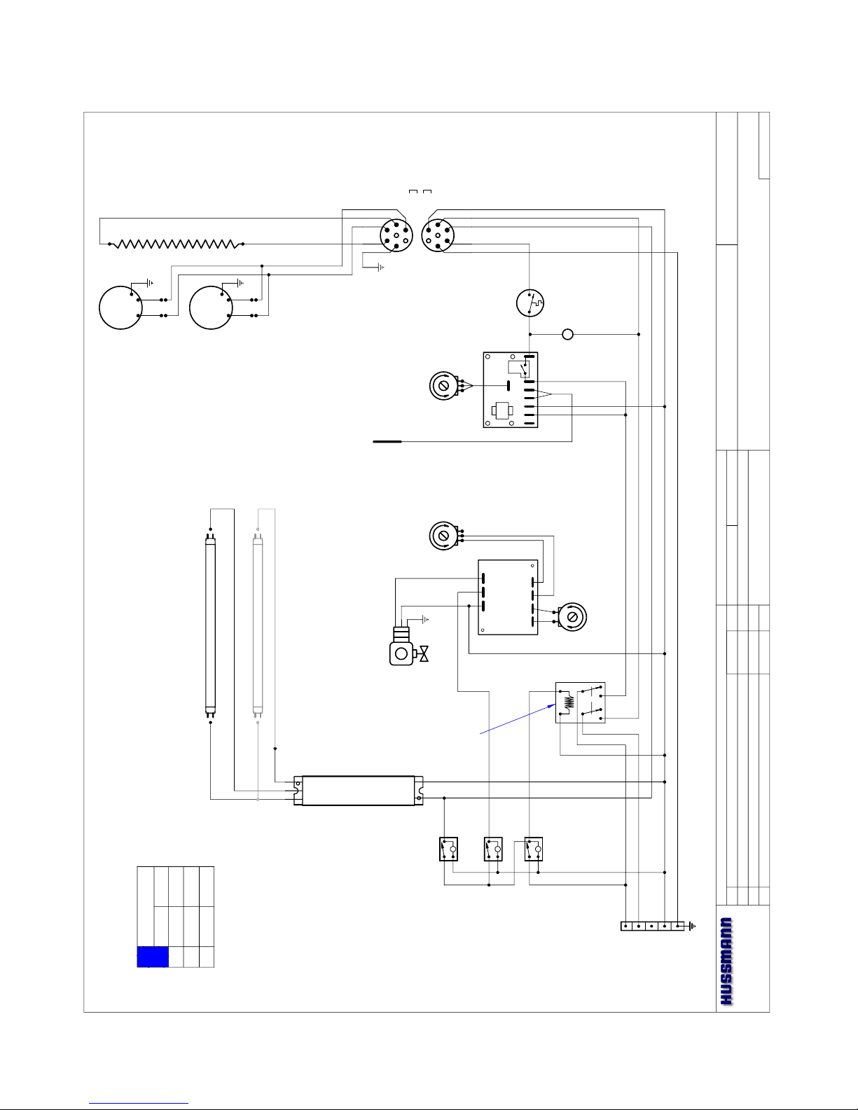
POWER SUPPLY: ~ 208 VAC / 1 Ø / 50-60 Hz. / 4 WIRE
32
1
4
56
7
TIMER SSAC
ESDR450A2
M
BL
BK W
R
G
M
AXIAL FANS
COMAIR MX2B1-EL
225-01-2012
HEATER HE-25 (125-02-1096)
1300 W @ ~ 240 VAC
LOADING
208 V 240 V
L1
L2
L3
5.5
4.8
~
6.1
5.4
~
W6800007
R3-HA (HOT AIR SYSTEM)
4' CASE - TOP SECTION ONLY
H:\WIRINGSCHEMATICS\NEWWIRE
29
Page 30

IGFP-R3H, R3HTO, R3HA, R3Combo-0208
Date:
Project Title:
Drawing No.:Drawn By:
Assembly: Drawing Title:
Date:
Hussmann Corporation, Int'l.
13770 Ramona Avenue
Chino, CA. 91710
(909)-590-4910 Lic.#: 644406
Revisions:
No. Description: Checked By:
By:
File Location:
Adrián E. Crisci
AEC
Sheet of
1
1
04/05/01
L
S
HEATER
FANS
G = GROUND
BK
W
BL
R
L
G
R
WBKBL
73
P1
5
12 4
6
G
N
L3
L2
L1
TERMINAL
BLOCK
L
L
BALLAST FULHAM
LH4-120-L
MAIN POWE R
WATER
LIGHTS &
FANS
ON TIME ADJ.
SSAC - VTP1A
0.5 M
Ω
OFF TIME ADJ.
SSAC - YP100416
1 M
Ω
WATER SOLENOID
204CD¼B¼B-EMS
225-01-3083
125-01-3267
CANOPY LIGHTS (2) FP28T5/830
SHELF LIGHT FP28T5/830 (OPTIONAL)
TEMP. SENSOR
225-01-3228
SAFETY T-STAT
NGT-11S11T444
225-01-3301A
PILOT
LIGHT
TEMPERATURE ADJ.
RELAY OMRON
G7L-2A-TUBJ-CB
125-01-3182
TRAK-STAT
225-01-3229
HEATER HE-25 (125-02-1096)
1300 W @ ~ 240 VAC
AXIAL FANS
COMAIR MX2B1-EL
225-01-2012
M
BL BK W
R
G
M
POWER SUPPLY: ~ 208 VAC / 1 Ø / 50-60 Hz. / 4 WIRE
32
1
4
56
7
TIMER SSAC
ESDR450A2
HEATER
FANS
G = GROUND
BK
W
BL
R
G
R
WBKBL
SAFETY T-STAT
NGT-11S11T444
225-01-3301A
HEATER HE-25 (125-02-1096)
1300 W @ ~ 240 VAC
AXIAL FANS
COMAIR MX2B1-EL
225-01-2012
M
BL BK W
R
G
M
125-01-3267
BALLAST FULHAM
LH4-120-L
LOADING
208 V 240 V
L1
L2
L3
10.9
9.6
~
12.1
10.8
~
W6800009
R3-HA (HOT AIR SYSTEM)
8' CASE - TOP SECTION ONLY
H:\WIRINGSCHEMATICS\NEWWIRE
30
Page 31

Rev.0208
Date:
Project Title:
Drawing No.:Drawn By:
Assembly: Drawing Title:
Date:
Hussmann Corporation, Int'l.
13770 Ramona Avenue
Chino, CA. 91710
(909)-590-4910 Lic.#: 644406
Revisions:
No. Description: Checked By:
By:
File Location:
Adrián E. Crisci
AEC
Sheet of
1
1
04/05/01
L
S
HEATER
FANS
G = GROUNDBKWBLR
L
G
R
WBKBL
73
P1
5
12 4
6
G
N
L3
L2
L1
TERMINAL
BLOCK
L
L
BALLAST FULHAM
LH4-120-L
MAIN POWER
WATER
LIGHTS &
FANS
ON TIME ADJ.
SSAC - VTP1A
0.5 M
Ω
OFF TIME ADJ.
SSAC - YP100416
1 M
Ω
WATER SOLENOID
204CD¼B¼B-EMS
225-01-3083
125-01-3267
CANOPY LIGHTS (2) FP28T5/830
SHELF LIGHTS (3) FP28T5/830 (OPTIONAL )
TEMP. SENSOR
225-01-3228
SAFETY T-STAT
NGT-11S11T444
225-01-3301A
PILOT
LIGHT
TEMPERATURE ADJ.
RELAY OMRON
G7L-2A-TUBJ-CB
125-01-3182
TRAK-STAT
225-01-3229
HEATER HE-25 (125-02-1096)
1300 W @ ~ 240 VAC
AXIAL FANS
COMAIR MX2B1-EL
225-01-2012
M
BL BK W
R
G
M
POWER SUPPLY: ~ 208 VAC / 1
Ø
/ 50-60 Hz. / 4
WIRE
32
1
4
56
7
TIMER SSAC
ESDR450A2
HEATER
FANS
G = GROUNDBKWBLR
G
R
WBKBL
SAFETY T-STAT
NGT-11S11T444
225-01-3301A
HEATER HE-25 (125-02-1096)
1300 W @ ~ 240 VAC
AXIAL FANS
COMAIR MX2B1-EL
225-01-2012
M
BL BK W
R
G
M
CANOPY LIGHT (1) FP28T5/830
125-01-3267
BALLAST FULHAM
LH4-120-L
BALLAST FULHAM
LH4-120-L
125-01-3267
CAP - IF NOT USED
HEATER
FANS
G = GROUNDBKWBLR
G
R
WBKBL
SAFETY T-STAT
NGT-11S11T444
225-01-3301A
HEATER HE-25 (125-02-1096)
1300 W @ ~ 240 VAC
AXIAL FANS
COMAIR MX2B1-EL
225-01-2012
M
BL BK W
R
G
M
LOADING
208 V 240 V
L1
L2
L3
16.4
14.4
~
18.2
16.3
~
W6800011
R3-HA (HOT AIR SYSTEM)
12' CASE - TOP SECTION ONLY
H:\WIRINGSCHEMATICS\NEWWIRE
31
Page 32

IGFP-R3H, R3HTO, R3HA, R3Combo-0208
Date:
Project Title:
Drawing No.:Drawn By:
Assembly: Drawing Title:
Date:
Hussmann Corporation, Int'l.
13770 Ramona Avenue
Chino, CA. 91710
(909)-590-4910 Lic.#: 644406
Revisions:
No. Description: Checked By:
By:
File Location:
Adrián E. Crisci
AEC
Sheet of
1
2
04/27/01
L
N
L3
L2
L1
G
S
L
MAIN POWER
CONTACTOR
~115 VAC COIL
TERMINAL BLOCK
~ 208VAC / ~ 240VAC - 50 / 60 Hz -3Ø - 5W
GRIDDLE HEATER PADS
(2) 342W ~ 240VAC
PILOT LIGHT
TRAK-STAT
225-01-3229
TEMPERATURE ADJ.
TEMP. SENSOR
225-01-3228
L
H1
L1
L2
H2
P
73
P1
5
12 4
6
L
H1
L1
L2
H2
P
HATCO GLOWRAY™ HEATERS
(2) 950W / ~240VAC 125-02-1086
BALLAST 125-01-3267
FULHAM LH4-120-L
L
FRONT CASE
LIGHT SWITCH
FRONT SHELF & CANOPY LIGHT
(2) FP28T5/830 LAMPS
TO UPPER CASE SECTION
TERMINAL BLOCK - SEE
PAGE 2 OF 2
NOTE:
CASE MUST BE GROUNDED
13.5
13.2
6.8
12.0
11.6
5.9
L1
L2
L3
208 V 240 V
LOADING
H:\WIRINGSCHEMATICS\NEW WIRE
R3-CASE W1800033
R3 HOT FRONT CASE + R3-HA TOP SECTION
Schematics
32
Page 33

Rev.0208
Date:
Project Title:
Drawing No.:Drawn By:
Assembly: Drawing Title:
Date:
Hussmann Corporation, Int'l.
13770 Ramona Avenue
Chino, CA. 91710
(909)-590-4910 Lic.#: 644406
Revisions:
No. Description: Checked By:
By:
File Location:
Adrián E. Crisci
AEC
Sheet of
L
S
HEATER
FANS
G = GROUND
BK
W
BL
R
L
G
R
WBKBL
73
P1
5
12 4
6
L
L
BALLAST FULHAM
LH4-120-L
MAIN POWER
WATER
LIGHTS &
FANS
ON TIME ADJ.
SSAC - VTP1A
0.5 M
Ω
OFF TIME ADJ.
SSAC - YP100416
1 M
Ω
WATER SOLENOID
204CD¼B¼B-EMS
225-01-3083
125-01-3267
CAP - IF NOT USED
CANOPY LIGHT FP28T5/830
SHELF LIGHT FP28T5/830 (OPTIONAL)
TEMP. SENSOR
225-01-3228
SAFETY T-STAT
NGT-11S11T444
225-01-3301A
PILOT
LIGHT
TEMPERATURE ADJ.
RELAY OMRON
G7L-2A-TUBJ-CB
125-01-3182
TRAK-STAT
225-01-3229
POWER SUPPLY: ~ 208 VAC / 1 Ø / 50-60 Hz. / 4 WIRE
32
1
4
56
7
TIMER SSAC
ESDR450A2
M
BL
BK W
R
G
M
AXIAL FANS
COMAIR MX2B1-EL
225-01-2012
HEATER HE-25 (125-02-1096)
1300 W @ ~ 240 VAC
N
L3
L2
L1
G
TO MAIN TERMINAL
BLOCK ON PAGE
1 OF 2
2
2
04/27/01
H:\WIRINGSCHEMATICS\NEW WIRE
R3-CASE W1800033
R3 HOT FRONT CASE + R3-HA TOP SECTION
Schematics
33
Page 34

Appendices
APPENDIX A. – Temperature Guidelines
Refrigerated
The refrigerators should be operated according to Hussmann’s
published engineering specifications for entering air temperatures for
specific equipment applications. Table 1 shows the typical temperature
of the air entering the food zone one hour before the start of defrost
and one hour after defrost for various categories of refrigerators.
Refer to Appendix C for Field Evaluation Guidelines.
TABLE 1
TYPE OF TYPICAL ENTERING
REFRIGERATOR AIR TEMPERATURE
I. OPEN DISPLAY
A. Non frozen:
1) Meat 28°F
2) Dairy/Deli 32°F
3) Produce
a. Processed 36°F
b. Unprocessed 45°F
B. Frozen 0°F
C. Ice Cream -5°F
II. CLOSED DISPLAY
A. Non frozen:
1) Meat 34°F
2) Dairy/Deli 34°F
3) Produce
a. Processed 36°F
b. Unprocessed 45°F
B. Frozen 0°F
C. Ice Cream -5°F
Single Deck Multi Deck ServiceCase Reach-In
I. Open Display Styles II. Closed Display Styles
Hot
1.0 Hot cases are tested to maintain all hot food at 140° - 150°.
These cases are not designed to heat up or cook food. It is the
user’s responsibility to stock the hot food cases immediately after
the cooking of the food with a pulp temperature of at least 150°
to 160°.
IGFP-R3H, R3HTO, R3HA, R3Combo-0208
APPENDIX B. – Application
Recommendations
Refrigerated
1.0 Temperature performance is critical for controlling bacteria
growth. Therefore, the following recommendations are included in
the standard. They are based on confirmed field experience over
many years.
1.1 The installer is responsible for following the installation instructions and recommendations provided by Hussmann for the
installation of each individual type refrigerator.
1.2 Refrigeration piping should be sized according to Hussmann's
equipment recommendations and installed in accordance with
normal refrigeration practices. Refrigeration piping should be
insulated according to Hussmann’s recommendations.
1.3 A clogged waste outlet blocks refrigeration. The installer is
responsible for the proper installation of the system which
dispenses condensate waste through an air gap into the building
indirect waste system.
1.4
The installer should perform a complete start-up evaluation prior to
the loading of food into the refrigerator, which includes such items as:
a) Initial temperature performance, Coils should be properly fed with
a refrigerant according to Hussmann’s recommendations.
b) Observation of outside influences such as drafts, radiant
heating from the ceiling and from lamps. Such influence should
be properly corrected or compensated for.
c) At the same time, checks should be made of the store dry-
bulb and wet-bulb temperatures to ascertain that they are
within the limits prescribed by Hussmann.
d) Complete start-up procedures should include checking through
a defrost to make certain of its adequate frequency and length
without substantially exceeding the actual needs. This should
include checking the electrical or refrigerant circuits to make
sure that defrosts are correctly programmed for all the
refrigerators connected to each refrigeration system.
e) Recording instruments should be used to check performance.
Hot
1.0
The installer should perform a complete start-up evaluation prior to
the loading of food into the hot food case, which includes such items
as:
a) Initial temperature performance, Griddles and Hot Wells.
b) Observation of outside influences such as drafts, radiant
heating from the ceiling and from lamps. Such influence should
be properly corrected or compensated for.
c) Complete start-up procedures should include :
1. Heat / display lamps are lighting
2. Indicator lamps on control panel(s) are working
3. Auto-fill is functioning properly (Service cases)
4. Hot Griddles are functioning.
34
Page 35

Rev.0208
APPENDIX C. – Field Recommendations Refrigerated
Recommendations for field evaluating the performance of retail
food refrigerators and hot cases
1.0 The most consistent indicator of display refrigerator performance
is the temperature of the air entering the product zone (Refrigerated see Diagram 1, Appendix A). In practical use, the precise
determination of return air temperature is extremely difficult.
Readings of return air temperatures will be variable and results
will be inconsistent. The product temperature alone is not an
indicator of refrigerator performance.
NOTE: Public Health will use the temperature of the product in
determining if the refrigerator will be allowed to display potentially
hazardous food. For the purpose of this evaluation, product
temperature above the FDA Food Code 1993 temperature for
potentially hazardous food will be the first indication that an evaluation
should be performed. It is expected that all refrigerators will keep food
at the FDA Food Code 1993 temperature for potentially hazardous food.
1.1 The following recommendations are made for the purpose of
arriving at easily taken and understood data which, coupled with
other observations, may be used to determined whether a display
refrigerator is working as intended:
a) INSTRUMENT – A stainless steel stem-type thermometer is
recommended and it should have a dial a minimum of 1 inch
internal diameter. A test thermometer scaled only in Celsius or
dually scaled in Celsius and Fahrenheit shall be accurate to 1°C
(1.8°F). Temperature measuring devices that are scaled only in
Fahrenheit shall be accurate to 2°F. The thermometer should
be checked for proper calibration. (It should read 32°F when
the stem is immersed in an ice water bath).
b) LOCATION – The probe or sensing element of the thermometer
should be located in the airstream where the air first enters
the display or storage area, and not more than 1 inch away
from the surface and in the center of the discharge opening.
c) READING – It should first be determined that the refrigerator
is refrigerating and has operated at least one hour since the
end of the last defrost period. The thermometer reading should
be made only after it has been allowed to stabilize, i.e.,
maintain a constant reading.
d) OTHER OBSERVATIONS – Other observations should be made
which may indicate operating problems, such as unsatisfactory
product, feel/appearance.
e) CONCLUSIONS – In the absence of any apparent undesirable
conditions, the refrigerator should be judged to be operating
properly. If it is determined that such condition is undesirable,
i.e., the product is above proper temperature, checks should be
made for the following:
1. Has the refrigerator been loaded with warm product?
2. Is the product loaded beyond the “Safe Load Line” markers?
3. Are the return air ducts blocked?
4. Are the entering air ducts blocked?
5.
Is a dumped display causing turbulent air flow and mixing with room air?
6. Are spotlights or other high intensity lighting directed onto the
product?
7. Are there unusual draft conditions (from heating /air-conditioning
ducts, open doors, etc.)?
8. Is there exposure to direct sunlight?
8. Are display signs blocking or diverting airflow?
9. Are the coils of the refrigerator iced up?
11. Is the store ambient over 75°F, 55% RH as set forth in ASHRAE
Standard 72 and ASHRAE Standard 117?
12. Are the shelf positions, number, and size other than recommended
by Hussmann?
13. Is there an improper application or control system?
14. Is the evaporator fan motor/blade inoperative?
15. Is the defrost time excessive?
16. Is the defrost termination, thermostat (if used) set too high?
17. Are the refrigerant controls incorrectly adjusted?
18. Is the air entering the condenser above design conditions? Are the
condenser fins clear of dirt, dust, etc.?
19. Is there a shortage of refrigerant?
20. Has the equipment been modified to use replacements for CFC-12,
CFC-502 or other refrigerant? If so, have the modifications been
made in accordance with the recommendations of Hussmann's
equipment? Is the refrigerator charged with the proper refrigerant
and lubricant? Does the system use the recommended compressor?
Hot
1.0 The most consistent indicator of display hot case performance is
temperature of the product itself.
NOTE: Public Health will use the temperature of the product in
determining if the hot case will be allowed to display potentially
hazardous food. For the purpose of this evaluation, product
temperature above the FDA Food Code 1993 temperature for
potentially hazardous food will be the first indication that an evaluation
should be performed. It is expected that all hot cases will keep food
at the FDA Food Code 1993 temperature to prevent the sale of
potentially hazardous food.
1.1 The following recommendations are made for the purpose of
arriving at easily taken and understood data which, coupled with
other observations, may be used to determined whether a display
refrigerator is working as intended:
a) INSTRUMENT – A stainless steel stem-type thermometer is
recommended and it should have a dial a minimum of 1 inch
internal diameter. A test thermometer scaled only in Celsius or
dually scaled in Celsius and Fahrenheit shall be accurate to 1°C
(1.8°F). Temperature measuring devices that are scaled only in
35
Page 36

IGFP-R3H, R3HTO, R3HA, R3Combo-0208
Fahrenheit shall be accurate to 2°F. The thermometer should be
checked for proper calibration. (It should read 32°F when the
stem is immersed in an ice water bath).
b) LOCATION – The thermometer must be inserted into the food
itself to acquire proper food pulp temperature.
c) READING – The thermometer reading should be made only
after it has been allowed to stabilize, i.e., maintain a constant
reading.
Loading Product: Cases should be allowed to heat up for one
hour before product is loaded.
Temperature adjustments: Allow 4 hours after adjustment has
been made before testing pulp temperature of product.
d) OTHER OBSERVATIONS – Other observations should be made
which may indicate operating problems, such as unsatisfactory
product, feel/appearance.
APPENDIX D. – Recommendations to user
Refrigerated
1.0 Hussmann should provide instructions and recommendations for
proper periodic cleaning. The user will be responsible for such
cleaning, including the cleaning of low temperature equipment within
the compartment and the cooling coil area(s). Cleaning practices,
particularly with respect to proper refrigerator unloading and warmup, must be in accordance with applicable recommendations.
1.1 Cleaning of non frozen food equipment should include a weekly cleaning
of the food compartment as a minimum to prevent bacteria growth from
accumulating. Actual use and products may dictate more frequent cleaning.
Circumstances of use and equipment design must also dictate the frequency
of cleaning the display areas. Weekly washing down of the storage
compartment is also recommended, especially for equipment subject to
drippage of milk or other liquids, or the collection of vegetable, meat,
crumbs, etc. or other debris or litter. Daily cleaning of the external areas
surrounding the storage or display compartments with detergent and water
will keep the equipment presentable and prevent grime buildup.
1.2 Load levels as defined by Hussmann must be observed.
1.3 The best preservation is achieved by following these rules:
a) Buy quality products.
b) Receive perishables from transit equipment at the ideal temperature
for the particular product.
c) Expedite perishables to the store’s storage equipment to avoid
unnecessary warm-up and prolonged temperature recovery. Food
store refrigerators are not food chillers nor can they reclaim quality
lost through previous mishandling.
d) Care must be taken when cross merchandising products to ensure
that potentially hazardous vegetable products are not placed in non
refrigerated areas.
e) Display and storage equipment doors should be kept closed during
periods of inactivity.
f) Minimize the transfer time of perishables from storage to display.
g) Keep meat under refrigeration in meat cutting and processing area
except for the few moments it is being handled in processing. When
a cut or tray of meat is not to be worked on immediately, the
procedure should call for returning it to refrigeration.
h) Keep tools clean and sanitized. Since mechanical equipment is used
for fresh meat processing, all such equipment should be cleaned at
least daily and each time a different kind of meat product comes
in contact with the tool or equipment.
i) Make sure that all refrigeration equipment is installed and adjusted
in strict accordance with Hussmann’s recommendations.
j) See that all storage and refrigeration equipment is kept in proper
working order by routine maintenance.
Hot
1.0 Hussmann should provide instructions and recommendations for
proper periodic cleaning. The user will be responsible for such
cleaning, including the cleaning of equipment within the compartment
and the hot area(s). Cleaning practices, particularly with respect to
proper refrigerator unloading and warm-up, must be in accordance
with applicable recommendations.
1. Allow the case to preheat for one hour prior to loading.
2. Hot foods should enter the case directly after cooking or no
lower than 150° - 160°F. The Hot Cases are not designed to
heat up or cook food.
3. Self Service - be sure to display product in single layer in
direct contact with heating surface and/or wire rack.
4. All griddle type units are designed to maintain termperatures
above the FDA guideline of 140°F. This is product temperature,
not air or griddle temperature. Due to the open design of
these units, they must be loaded with product for proper
operation. When units are empty, they experience rapid rise of
heated air from air outside the case. This action gives empty
units a false, lower than desired, temperature reading. Loading
the case traps the air at the griddle, raising temperatures to
the 165°F to 185°F range, keeping product well above the
FDA guidelines. Remember, these units must be loaded with
product to maintain safe product temperature.
5. Check the food pulp temperature frequently with a thermometer to make sure it is at the proper holding temperature. Hot
foods should be at 140°. The thermometer must be inserted
into the food itself for the proper temperature.
6. Do not display more food than will be sold within a 4 hour
period.
7. When restocking, bring older food to the front, and stock
fresher food on top.
8. Clean spills as soon as they happen.
9. Fingerprints and food splatter will drastically shorten bulb life.
Clean splatter off the bulbs immediately with a soft cloth.
When handling bulbs, wear cotton gloves or use a cotton rag /
36
Page 37

Rev.0208
towel.
10. When “freshening” foods such as macaroni and cheese with
added water, heat the water in a clean container until it is
10° to 20°F above the desired holding temperature of the
food. This will keep the food at a safe serving temperature.
Depending on the amount of water, the temperature can drop
10° to 20° in as little as five minutes.
11. When transferring hot foods in the heated merchandiser to
clean pans, preheat the clean pan. Transferring hot foods to
room temperature pans can cause the temperature of the food
to drop 20° or more thus causing food to be at an unsafe
serving temperature.
12. Clean spills as they happen simply by wiping with a cloth. Be
sure to use a dry cloth on very hot surfaces to prevent steam
burns.
13. Turn the equipment off and allow to cool before cleaning.
14. To remove “baked-on” splatter from Stainless Steel, the
following may be used
Grade F Italian Pumice Scour or rub with a damp cloth
Liquid Nusteel Scour with a small amount of a dry
cloth
Paste NuSteel
Household Cleaners Rub with a damp cloth
Coopers Stainless Steel Cleaner
Allen Stainless Steel Polish
37
Page 38

IGFP-R3H, R3HTO, R3HA, R3Combo-0208
38
Page 39

Rev.0208
LIMITED WARRANTY
This warranty is made to the original user at the original installation site and is not transferable.
Hussmann merchandisers are warranted to be free from defect in material and workmanship under normal use and service for a period of one (1)
year from the date of original installation (not to exceed fifteen (15) months from the date of shipment for the factory). Hussmann Impact
Modular Coils are warranted for a total of five (5) years based upon the above criteria. Hussmann’s obligation
under this warranty shall be limited to repairing or exchanging any part or parts, without charge F.O.B. factory or nearest authorized parts depot
within said period and which is proven to the satisfaction of the original manufacturing plant warranty group to be thus defective.
Hussmann covers the entire case or refrigeration product and all its components (except for lamps, driers, fuses, and other maintenance type
replacement parts) for the one (1) year warranty period.
Additionally, Hussmann warrants for a total period of three (3) years all sealed, multi-glass assemblies except those used in sliding doors on closed
meat display cases. If within three (3) years from the date of installation (not to exceed thirty-nine (39) months from the date of shipment from
factory), it shall be proven to the satisfaction of the originating factory warranty group that there is impaired visibility through the multi-glass
assemblies thereof caused by moisture between the glasses, the multi-glass assembly will be replaced free of charge, F.O.B. factory. This additional
warranty excludes accident, misuse, or glass breakage.
On Hussmann manufactured self-contained display cases, Hussmann agrees to repair or exchange, at its option, the original motor/compressor unit only
with a motor/compressor of like or of similar design and capacity if it is shown to the satisfaction of Hussmann that the motor/compressor is
inoperative due to defects in factory workmanship or material under normal use and service as outlined in Hussmann’s “Installation Instructions” which
are shipped inside new Hussmann equipment. Hussmann’s sole obligation under this warranty shall be limited to a period not to exceed five years
from date of factory shipment.
On Hussmann refrigeration systems, an additional (4) year extended warranty for the motor/compressor assembly is available, but must be purchased
prior to shipment to be in effect. Hussmann reserves the right to inspect the job site, installation and reason for failure.
The motor/compressor warranties listed above do not include replacement or repair of controls, relays, capacitors, overload protectors, valve plates, oil
pumps, gaskets or any external part on the motor/compressor replaceable in the field, or any other part of the refrigeration system or self-contained
display case.
THE WARRANTIES TO REPAIR OR REPLACE ABOVE RECITED ARE THE ONLY WARRANTIES, EXPRESS, IMPLIED
OR STATUTORY, MADE BY HUSSMANN WITH RESPECT TO THE ABOVE MENTIONED EQUIPMENT, INCLUDING
ANY IMPLIED WARRANTY OF MERCHANTABILITY OR FITNESS, AND HUSSMANN NEITHER ASSUMES NOR
AUTHORIZES ANY PERSON TO ASSUME FOR IT, ANY OTHER OBLIGATION OR LIABILITY IN CONNECTION WITH
THE SALE OF SAID EQUIPMENT OR ANY PART THEREOF.
THIS WARRANTY SHALL NOT APPLY TO LOSS OF FOOD OR CONTENTS OF THE EQUIPMENT DUE TO FAILURE
FOR
ANY REASON. HUSSMANN SHALL NOT BE LIABLE:
• For payment of labor for any removal or installation of warranted parts;
• For any repair or replacements made without the written consent of Hussmann, or when the equipment is installed or operated in a manner
contrary to the printed instructions covering installation and service which accompanied such equipment;
• For any damages, delays, or losses, direct or consequential which may arise in connection with such equipment or part thereof;
• For damages caused by fire, flood, strikes, acts of God or circumstances beyond its control;
• When the equipment is subject to negligence, abuse, misuse or when the serial number of the equipment has been removed, defaced, or altered;
• When the equipment is operated on low or improper voltages
• When the equipment is put to a use other than normally recommended by Hussmann (i.e. deli case used for fresh meat);
• When operation of this equipment is impaired due to improper drain installation;
• For payment of refrigerant loss for any reason;
• For costs related to shipping or handling of replacement parts.
39
Page 40

IGFP-R3H, R3HTO, R3HA, R3Combo-0208
Service Record
Last service date: By:
/Chino
Additional copies of this publication may be obtained by contacting:
Hussmann® Chino
13770 Ramona Avenue • Chino, California 91710
(909) 628-8942 FAX
(909) 590-4910
(800) 395-9229
The MODEL NAME and SERIAL NUMBER is required in order to provide you
with the correct parts and information for your particular unit.
They can be found on a small metal plate on the unit.
Please note them below for future reference.
MODEL:
SERIAL NUMBER:
40
 Loading...