

Page 1
HUSSMANN CORPORATION, Bridgeton, MO 63044-2483 U.S.A.
P/N 0417990A
PWW
Data Sheet Set
P/N 0417990A
NSF
®
Certified
May 2004
NOTE: Changed items have been underlined.
®
Item Part # Description Wiring Item #
FAN ASSEMBLIES, AND THERMOSTATS
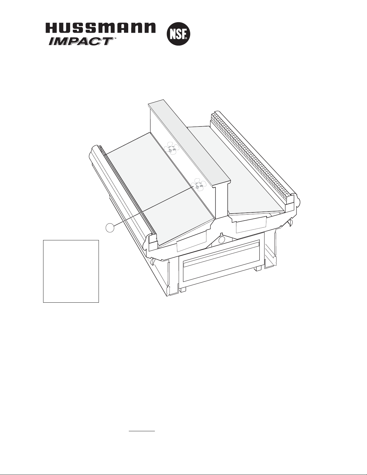
(A) 0378349 Fan Motor, Evaporator (1)
0142780 Fan Blade
Embossing toward motor
We reserve the right to change
or revise specifications and
product design in connection
with any feature of our
products. Such changes
do not entitle the buyer to
corresponding changes,
improvements, additions or
replacements for equipment
previously sold or shipped.
Merchandisers
A
Page 2
PWW Data Sheet
HUSSMANN CORPORATION, Bridgeton, MO 63044-2483 U.S.A.
2 of 4
Engineering
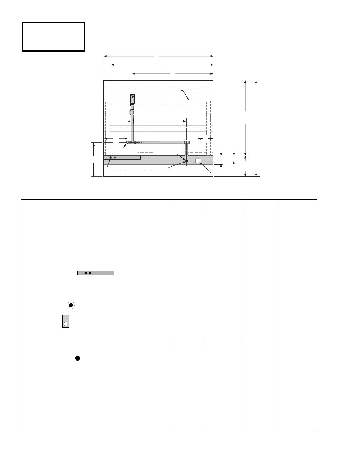
Plan Views
86 Inch
Wide Island
Bulk Produce
07-2003
Dimensions are shown as inches & (mm).
General 4 Ft 6 Ft 8 Ft 12 Ft
(A) Case length 48 1/4 (1226) 72 1/4 (1835) 96 3/8 (2448) 144 1/2 (3670)
Maximum outside dimension of case back to front 86 1/2 (2197) 86 1/2 (2197) 86 1/2 (2197) 86 1/2 (2197)
(includes bumper)
Front of splashguard to outside edge of base rail 5 7/8 (149) 5 7/8 (149) 5 7/8 (149) 5 7/8 (149)
Back of case to outside edge of front base rail 69 1/2 (1765) 69 1/2 (1765) 69 1/2 (1765) 69 1/2 (1765)
Front of case to outside ede of front base rail 17 (432) 17 (432) 17 (432) 17 (432)
Width of base rail 2 1/8 (54) 2 1/8 (54) 2 1/8 (54) 2 1/8 (54)
Stub up area between front base rail and splashguard 4 7/8 (124) 4 7/8 (124) 4 7/8 (124) 4 7/8 (124)
Electrical Service
(B) Righthand end of case to center of farthest knockout 47 1/4 (1202) 71 1/4 (1810) 95 3/8 (2423) 143 5/8 (3650)
Length of electrical raceway 11 7/8 (303) 34 5/8 (878) 34 5/8 (878) 34 5/8 (878)
*Note: Electrical field wiring connection point.
Waste Outlet
(C) Right end of case to center of waste outlet 24
1
/8
(613) 46
5
/8
(1184) 72
1
/4
(1835) 72
1
/4
(1835)
Water Seal
Edge of water seal to center of waste outlet 4 (102) 4 (102) 4 (102) 4 (102)
Center of waste outlet to outside edge of front base rail 3
1
/2 (89) 3 1/2 (89) 3 1/2 (89) 3 1/2 (89)
** Note: Field installed water seal outlets, tees, and connectors are shipped with case
Drip Pipe Outlet
(D) Left end of case to center of drip pipe outlet 20 3/8 (517) 19 1/2 (495) 19 1/2 (495) 68 1/2 (1740)
(E) Center of waste outlet to center of drip pipe outlet 3
3
/4
(95) 24
3
/4
(629) 51
7
/8
(1318) 3
3
/4
(95)
(F) Front of case to center of drip pipe outlet 24
7
/8 (632) 25 7/8 (657) 25 7/8 (657) 24 7/8 (632)
Outside diameter of drip pipe lines 1
1
/2 (38) 1 1/2 (38) 1 1/2 (38) 1 1/2 (38)
***Note: Field drip pipe connection point.
Refrigeration Outlet
(D) Right end of case to center of refrigeration outlet 9 (230) 9 (230) 9 (230) 9 (230)
Center of refrigeration outlet to outside edge
of front base rail 3 1/2 (89) 3 1/2 (89) 3 1/2 (89) 3 1/2 (89)
A
B
C
Base Rail
PWW-8
69 1/2
3 1/2
(89)
(1765)
17
(432)
86 1/2
(2197)
C
L
F
D
(See Note***)
(See Note*)
E
(See Note**)
Access Area
Waste Outlet
& Water Seal
Refrigeration
Outlet
G
5 7/8
(149)
Front
Page 3

P/N 0417990A 3 of 4
HUSSMANN CORPORATION, Bridgeton, MO 63044-2483 U.S.A.
Impact
PWW
Produce
Wide Island, 1 Display Level
REFRIGERATION DATA
Note: This data is based on store temperature
and humidity that does not exceed 75°F and
55% R.H.
PWW
4,6,8,12E
Discharge Air (°F) 34
Evaporator(°F) 24
Unit Sizing (°F) 22
Btu/hr/ft* PWW
4,6,8,12E
Parallel 1200
Conventional 1325
*For all refrigeration equipment other than
Hussmann, use conventional Btu values.
DEFROST DATA
PWW
4,6,8,12
Frequency (hr) 6
Defrost Water (lb/ft/day) 8
(± 15% based on case configuration and
product loading).
O
FFTIME
PWW
4,6,8,12E
Temp Term (°F) N/A
Failsafe (minutes) 45
CONVENTIONAL CONTROLS
Low Pressure Backup Control
PWW
4,6,8,12E
CI/CO** 17°/ 7° F
Indoor Unit Only, Pressure Defrost
Termination** 48° F
**Use a Temperature Pressure Chart to
determine PSIG conversions.
PHYSICAL DATA
Merchandiser Drip Pipe (in.) 11/2
Liquid Line (in.)
3
/8
Suction Line (in.)
7
/8
Estimated Charge (lb)*** PWW
4,6,8,12E
4 ft 1.4
6 ft 2.3
8 ft 2.8
12 ft 4.3
***This is an average for all refrigerant types.
Actual refrigerant charge may vary by
approximately half a pound.
Length Added to Lineup by
Each End/Partition (in.) 1 1/2
NSF Certification
These merchandisers are manufactured to meet ANSI /National
Sanitation Foundation (NSF
®
) Standard #7 requirements.
Dimensions are shown as inches & (mm).
PWW
6 (152)
33 3/4
(857)
44
(1118)
Front
of
Case
30 3/8
(772)
25 1/2
(648)
Electrical
17 3/8
(441)
17
(432)
15
(381)
COIL
5 1/2
(114)
5 7/8 (149)
3 1/2 (89)
3 1/2 (89)
FAN
86 1/2
(2197)
Optional
Rack
Positions
33 3/4
(857)
COIL
12 3/8
(314)
C
L
69 1/2
(1765)
Page 4

PWW Data Sheet
HUSSMANN CORPORATION, Bridgeton, MO 63044-2483 U.S.A.
4 of 4
Impact PWW
Produce
Electrical Data
Number of Fans 4 ft 6 ft 8 ft 12 ft
Refrigeration — 9W 1 1 2 3
Refrigeration — 9W (Export) 1 1 2 3
Amperes Watts
Merchandiser 4 ft 6 ft 8 ft 12 ft 4 ft 6 ft 8 ft 12 ft
Fans (Refrigeration)
Standard (120V 60Hz) 0.77 0.77 1.54 2.31 62 62 124 186
Energy Efficient (120V 60Hz) 0.38 0.38 0.76 1.14 25 25 50 75
Export (230V 50 Hz) 0.47 0.47 0.94 1.41 70 70 140 210
Min. Circuit Ampacity
With Standard Fans (120V 60Hz) 0.97 0.97 1.74 2.51
With Energy Efficient Fans (120V 60Hz) 0.58 0.58 0.96 1.34
With Export Fans (230V 50 Hz) 0.67 0.67 1.14 1.61
Maximum Over Current Protection 120V 20 20 20 20
Maximum Over Current Protection 230V 15 15 15 15
Standard Lighting Optional Lighting Optional Shelf Lighting
None None None
Fan Wiring
Offtime Defrost
120V POWER
BROWN BAND
All components must have a mechanical ground, and the merchandiser must be grounded.
CIRCLED NUMBERS = PARTS LIST ITEM NUMBERS
1, 2 & 3 Fans
4 ft, 6 ft
WARNING
= 120V POWER
Fans
1
8 ft 12 ft
= 120V NEUTRAL
120V NEUTRAL
ROWN BAND
B
 Loading...