

Page 1

Medium Temperature
Meat, Delicatessen, Dairy and Produce
Merchandisers
Installation &
Operation Manual
Shipped With Case Data Sheets
P/N 0378414G
Impact Series
August 2004
IIMMPPOORRTTAANNTT
Keep in store for
future reference!
®
Merchandisers
Page 2

INSTALLATION
NSF Certification . . . . . . . . . . . . . . . . . . . . 1-1
Location . . . . . . . . . . . . . . . . . . . . . . . . . . . 1-1
Shipping Damage . . . . . . . . . . . . . . . . . . . . 1-1
Exterior Loading . . . . . . . . . . . . . . . . . . . . . 1-2
Merchandisers Shipped with End Installed . . 1-2
Shipping Braces . . . . . . . . . . . . . . . . . . . . . . 1-2
Leveling . . . . . . . . . . . . . . . . . . . . . . . . . . . 1-2
Joining Instructions . . . . . . . . . . . . . . . . . . . 1-4
Splashguard Bracket and Joint Support . . . . 1-6
Offsetting Bumpers and Top Rail . . . . . . . . . 1-7
REFRIGERATION / ELECTRICAL
Refrigerant . . . . . . . . . . . . . . . . . . . . . . . . . 2-1
Refrigerant Piping . . . . . . . . . . . . . . . . . . . . 2-1
Insulation . . . . . . . . . . . . . . . . . . . . . . . . . . . 2-2
Suction Line . . . . . . . . . . . . . . . . . . . . . . . . 2-2
Liquid Line . . . . . . . . . . . . . . . . . . . . . . . . . 2-2
Refrigeration Thermostat . . . . . . . . . . . . . . . 2-3
Defrost Termination Thermostat . . . . . . . . . 2-3
Defrost Sequences . . . . . . . . . . . . . . . . . . . . 2-3
Merchandiser Electrical Data . . . . . . . . . . . . 2-4
Electrical Connections . . . . . . . . . . . . . . . . . 2-4
Field Wiring . . . . . . . . . . . . . . . . . . . . . . . . 2-4
Identification of Wiring . . . . . . . . . . . . . . . . 2-4
DRIP PIPING AND SPLASHGUARDS
Waste Outlet and Water Seal . . . . . . . . . . . . 3-1
Installing Drip Piping . . . . . . . . . . . . . . . . . 3-1
Installing Splashguards and
Lower Front Panels . . . . . . . . . . . . . . . . . . 3-3
Sealing Splashguard to Floor . . . . . . . . . . . 3-4
START UP / OPERATION
Start up . . . . . . . . . . . . . . . . . . . . . . . . . . . . 4-1
Load Limits . . . . . . . . . . . . . . . . . . . . . . . . . 4-1
Stocking . . . . . . . . . . . . . . . . . . . . . . . . . . . 4-1
Multi-deck Shelf Alignment . . . . . . . . . . . . . 4-2
Multi-deck Shelf Configuration . . . . . . . . . . 4-2
Installing Lighted Shelves . . . . . . . . . . . . . . 4-2
Installing FDA/NSF Required Thermometer 4-4
MAINTENANCE
Care and Cleaning . . . . . . . . . . . . . . . . . . . . 5-1
Cleaning Under Merchandisers . . . . . . . . . . 5-2
Cleaning Mirrors . . . . . . . . . . . . . . . . . . . . . 5-2
Cleaning Honeycomb Assemblies . . . . . . . . 5-3
Removing Interior Back Panels . . . . . . . . . . 5-4
Removing Scratches from Bumper . . . . . . . 5-4
SERVICE
Replacing Fan Motors and Blades . . . . . . . . 6-1
Replacing Fluorescent Lamps . . . . . . . . . . . 6-2
Replacing Lamp-holders and End Caps . . . . 6-2
Replacing Electronic Ballasts . . . . . . . . . . . . 6-3
Replacing Damaged Drain Fitting . . . . . . . . 6-4
Repairing Aluminum Coils . . . . . . . . . . . . . 6-4
WARRANTY
REVISION G
1. Changed starter bumper, page 1-7.
2. Added bumper film removal, page 1-8.
3. Added installing optional stainless steel splashguard,
separated sealing standard and optional splashguards to
floor, pages 3-3 and 3-4.
4. Updated load limit profiles, pages 4-1 and 4-2.
5. Updated shelf bracket profile, page 4-2.
6. Added do not use ammonia-based cleaners on acrylic
parts, page 5-1.
7. Added damaged honeycomb must be replaced,
page 5-3.
IMPORTANT
KEEP IN STORE FOR FUTURE REFERENCE
Quality that sets industry standards.
12999 St. Charles Rock Road • Bridgeton, MO 63044 U.S.A. • (314) 291-2000 • FAX (314) 298-4767
TABLE OF CONTENTS
P/N 0378414G
®
Page 3

Medium Temperature
P/N 0378414G 1-1
HUSSMANN CORPORATION • BRIDGETON, MO 63044-2483 U.S.A.
NSF CERTIFICATION
These merchandisers are manufactured to meet
ANSI / National Sanitation Foundation (NSF®)
Standard #7 requirements. Proper installation is
required to maintain certification. Near the serial
plate, each case carries a label identifying the
type of application for which the case was
certified.
ANSI/NSF-7 Type I – Display Refrigerator / Freezer
Intended for 75°F / 55%RH Ambient Application
ANSI/NSF-7 Type II – Display Refrigerator / Freezer
Intended for 80°F / 55%RH Ambient Application
ANSI/NSF-7 – Display Refrigerator
Intended for Bulk Produce
LOCATION
These merchandisers are designed for displaying
products in air conditioned stores where temperature is maintained at or below the ANSI / NSF-7
specified level and relative humidity is maintained
at or below 55%.
Placing refrigerated merchandisers in direct
sunlight, near hot tables or near other heat sources
could impair their efficiency.
Like other merchandisers, these are sensitive to
air disturbances. Air currents passing around
merchandisers will seriously impair their
operation. Do NOT allow air conditioning,
electric fans, open doors or windows, etc. to
create air currents around the merchandisers.
Product should always be maintained at proper
temperature. This means that from the time the
product is received, through storage, preparation
and display, the temperature of the product must
be controlled to maximize the life of the product.
The exterior frames on these cases provide space
for air circulation. However, in high ambient
conditions, sweating may still occur. If this
happens install a method of forced ventilation
such as a fan ventilation kit.
Wide Island Fronts
BE SURE TO POSITION WIDE ISLAND MERCHANDISER
FRONTS PROPERLY
. The front of wide island
merchandisers is readily identified by the location
of the serial plate (see leveling drawing on next
page). Since all electrical and refrigeration
connections will be made at the front side, the
fronts will need to be positioned according to the
store plan layout.
SHIPPING DAMAGE
All equipment should be thoroughly examined
for shipping damage before and during unloading.
This equipment has been carefully inspected at
our factory. Any claim for loss or damage must be
made to the carrier. The carrier will provide any
necessary inspection reports and/or claim forms.
Apparent Loss Or Damage
If there is an obvious loss or damage, it must be
noted on the freight bill or express receipt and
signed by the carrier’s agent; otherwise, carrier
may refuse claim.
Concealed Loss Or Damage
When loss or damage is not apparent until after
equipment is uncrated, retain all packing materials
and submit a written request to the carrier for
inspection, within 15 days.
INSTALLATION
Do not walk or put heavy objects on case.
CAUTION
!
Page 4

1-2 I
NSTALLATION
P/N 0378414G
EXTERIOR LOADING
Do NOT walk on top of merchandisers or
damage to the merchandisers and serious
personal injury could occur. T
HEY ARE NOT
STRUCTURALLY DESIGNED TO SUPPORT EXCESSIVE
EXTERNAL LOADING such as the weight of a
person. Do not place heavy objects on the case.
MERCHANDISERS SHIPPED WITH END INSTALLED
If the case was shipped with the end installed,
two long bolts were used to hold the shipping
brace to the end. If the shipping bolts are
reinserted after removing the brace, they will
extend into the product area. THEREFORE, BE
SURE TO REPLACE THESE BOLTS WITH THE SHORTER
BOLTS PROVIDED. NSF requires any bolt or screw
in the product area be capped or cut off if it has
more than three exposed threads.
NOTE:
Be careful not to damage the factory
installed end while moving the case.
Make sure that tools are positioned past
the end and beneath the merchandiser’s
support bar.
SHIPPING BRACES
Move the merchandiser as close
as possible to its permanent
location and then remove all
packaging. Check for damage
before discarding packaging.
Remove all separately packed
accessories such as kits and
shelves.
LEVELING
Merchandisers must be installed level to ensure
proper operation of the refrigeration system and
to ensure proper drainage of defrost water. When
leveling merchandisers, use a carpenter’s level as
shown. Leveling shims are provided with each
merchandiser for use if needed. The shims are big
enough so that you can level adjoining merchandisers at the same time using one shim.
NOTES:
• B
EGIN LINEUP LEVELING FROM THE HIGHEST POINT
OF THE STORE FLOOR.
• If shimming two corners, check to see if a shim is
needed in the center of the merchandiser. If a gap
exists between the support rail of the merchandiser
and the floor, a shim should be placed in the center.
Do NOT remove shipping braces until
the merchandisers are positioned
for installation.
Rear
Levels
Serial Plate
Front of
Merchandiser
!
WARNING
Page 5
Medium Temperature
P/N 0378414G 1-3
HUSSMANN CORPORATION • BRIDGETON, MO 63044-2483 U.S.A.
NOTE: Do not place levels
on Display Pans or
on Shelves.
Leveling Single Deck
Merchandisers
Leveling Multi-deck
Merchandisers
Levels
Levels
Shim
Page 6

1-4 I
NSTALLATION
P/N 0378414G
JOINING INSTRUCTIONS
Sectional construction means that two or more
merchandisers may be joined in line yielding one
long continuous display requiring only one pair
of ends.
ALL JOINTS MUST BE AIR
-TIGHT TO PREVENT
FORMATION OF ICE OR CONDENSATION.
Prep Case
1. Check to be sure that merchandisers are
level and that the factory-installed nut
retainers and alignment pins are in place.
Locate Joint Kit and check contents against
parts list.
2. Remove shelves (if installed), display racks,
pans, front shelf supports and front air
grilles from the right end.
3. Remove the rear panel(s) from the right end.
On multi-deck cases remove the lower back
panel first. To remove a panel lift it up from
its bottom edge and out. No tools are
required.
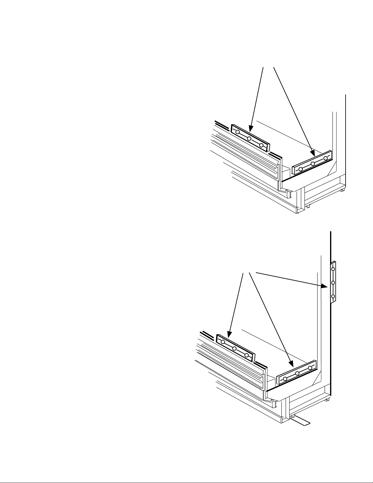
Apply Gaskets
1. Apply
1
/2 in. (13 mm) gasket in the horizontal
recess across the bottom and up the front of
the merchandiser as shown. Gasket should
cover slots.
2. Apply the 1
5
/8
in. (41 mm) gasket to cover
foam-to-metal gap at rear of case and across
the top as shown. Be sure to overlap gaskets
as shown. Check to be sure that there are no
gaps between gasket and merchandiser.
Fasten Cases
1. Move the second merchandiser into position
against the first. Match the alignment pins
with the corresponding holes.
2. Fasten fronts together using cap screws, flat
washers, lock washers and nuts. Tighten
only until front panels touch. Do not tighten
fully.
3. Use the cap screws, flat washers and lock
washers provided in the joint kit to draw
the merchandisers together at rear. Do not
tighten fully.
4. Draw canopies of multi-deck
wall merchandisers together
by inserting threaded rod
through top shoe as shown.
Fasten each end with washers
and nuts. Tighten only until
canopies touch.
5. Tighten joints in the order
shown (A, B, C, D) until
gaskets are compressed, and
cases join smoothly.
PW & MWG
models
C
B
15/8 in. Gasket (41 mm)
1
/2 in. Gasket (13 mm)
A
Page 7
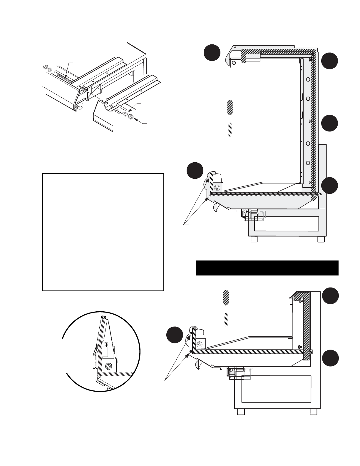
Connecting Canopies
of Multi-deck Wall Cases
Tighten in Order Shown
IMPORTANT
• Do not stretch gasket,
especially around corners.
• Do not butt gaskets;
always overlap them as shown.
• Remove paper backing
after gasket has been applied.
Medium Temperature
P/N 0378414G 1-5
HUSSMANN CORPORATION • BRIDGETON, MO 63044-2483 U.S.A.
Threaded
Rod
Flat Washer
Hex Nut
E
A
Alignment
Bullets
15/
in. Gasket
8
(41 mm)
1
/
in. Gasket
2
(13 mm)
D
C
B
Glass
Front
Detail
A
Alignment
Pins
15/
in. Gasket
8
(41 mm)
1
/
in. Gasket
2
(13 mm)
C
B
Page 8
1-6 I
NSTALLATION
P/N 0378414G
Seal Merchandisers
1. Apply butyl tape across the bottom joint. Be
sure to extend the tape up the back and front
of the case.
2. Use field-supplied silicone to fill any gaps
between the front support brackets.
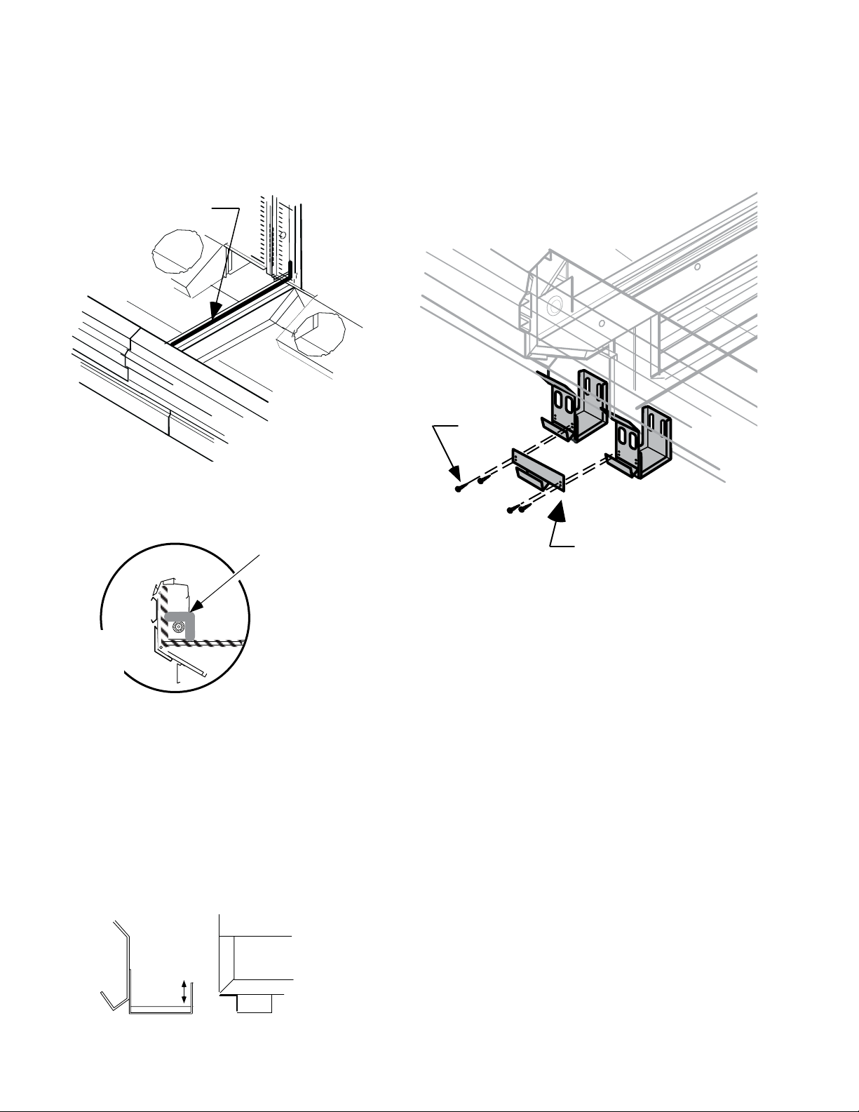
SPLASHGUARD BRACKET AND JOINT SUPPORT
Install Splashguard Bracket
Position splashguard brackets to the merchandiser
and level to the floor. Each bracket has a 1
1
/2 in.
(38 mm) slot at the rear of the bracket where it
attaches to the merchandiser. Tighten screws to
secure the brackets.
Install Splashguard Joint Support
Position the joint support across the brackets as
shown above. Fasten with hex head sheet metal
screws.
Butyl Tape
Screw
Silicone
Field Supplied
Front
Detail
Joint Support
Bracket
Base of Case
Page 9
Medium Temperature
P/N 0378414G 1-7
HUSSMANN CORPORATION • BRIDGETON, MO 63044-2483 U.S.A.
OFFSETTING BUMPERS AND TOP RAIL
Offsetting the bumpers and top rails helps to
disguise the joint locations, giving the lineup a
smoother look.
1. Locate starter bumpers and top rail. They are
shipped with the left-end kit.
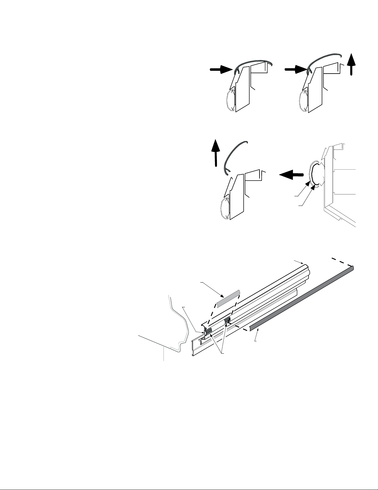
2. Remove factory installed top rails and
bumpers from cases as follows:
a. To remove top rails, push rail toward the
back of the case with one hand while lifting the top edge off the light channel with
the other hand. See drawing below.
b. Starting at one end, carefully peel bottom
of top rail free of color panel and set the
rail inside the case.
c. Remove upper and lower bumpers by
pulling bumper away from bumper retainers. Be careful not to lose the internal
joint trims on the upper bumpers.
3. Starting at the left end of the line up, install
the upper bumper starter section first. To
install,
a. Position internal
joint trims so that the
first is flush to the
left-end panel and
the second is centered between the
starter bumper and
the full length
bumper as shown
below.
b. Install full length bumpers and internal
trims offset across joints. Make sure that
no gaps exist between sections. Continue
installing the upper bumpers the length of
the line up. Do NOT install the last upper
bumper section at this time. This section
will be installed in the last step.
4. Install lower bumper starter and full length
lower bumpers by simply pushing them into
place. There are no internal joint trims on the
lower bumpers.
Step 2-b.
Step 2-a.
Step 2-c.
Retainer
Merchandiser
Joint
Full Length
Bumper
Starter
Bumper
Internal Joint Trims
Push
Pull
Lift
Push
Pull
Upper
Bumper
Internal
Joint Trim
Page 10
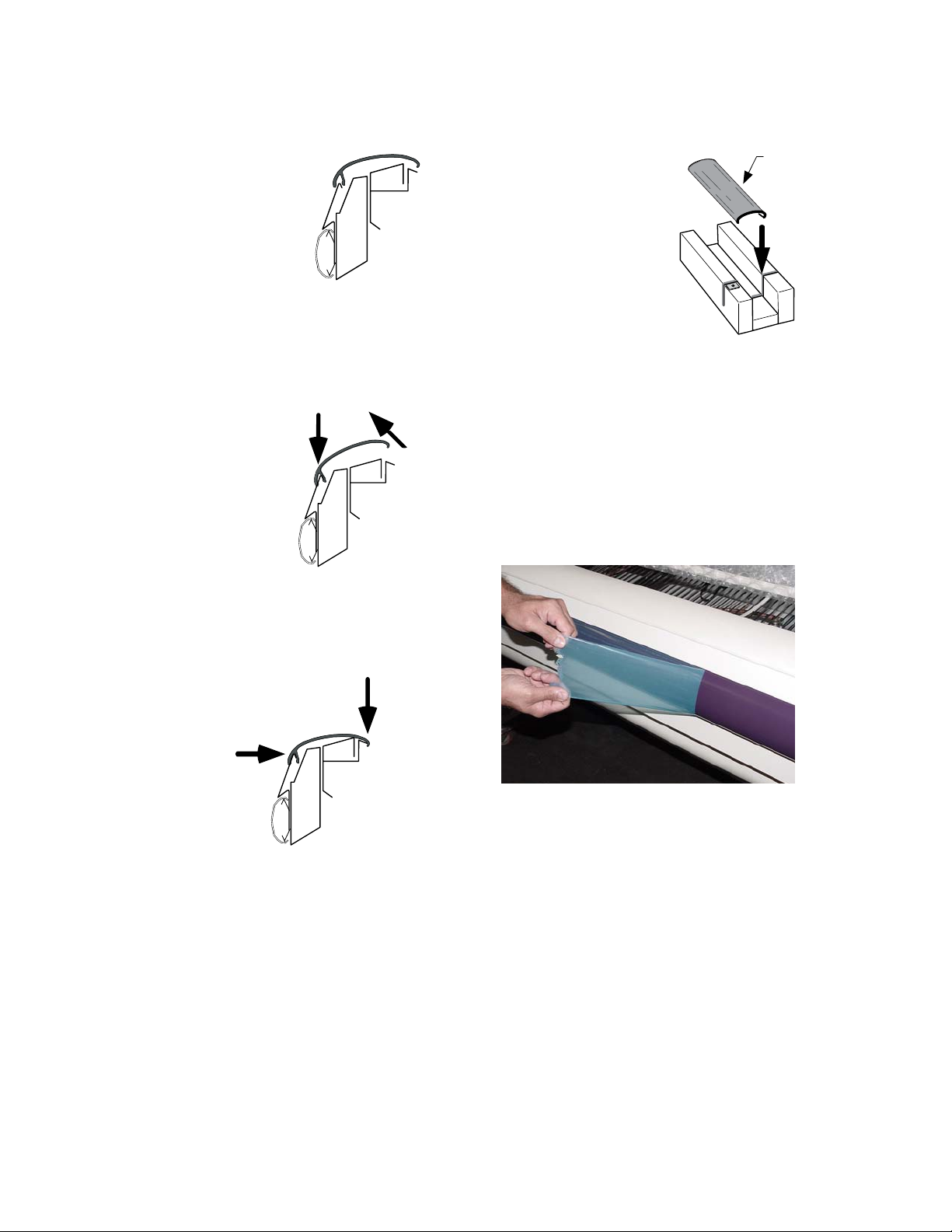
5. Return to the left end of the line up and
position the starter section of the top rail
as shown.
NOTE: The top rail
should not be installed
until the upper bumper
is securely in place.
6. Push the bottom portion of
the short top rail section down over the color
panel. It helps if you lift the top with your
other hand as shown. You will hear and feel
the trim “snap” into place.
NOTE: The trim
must “snap” to
be properly
positioned.
7. Use one hand to push the top rail toward the
rear of the case while using the other hand to
“snap” the top section down over the edge of
the light channel as shown.
Again, be sure
it “snaps”
into place.
8. Install full length top rails using the same
procedures. Continue installing the top rails
the length of the line up. Do NOT install last
section at this time.
9. Once all except the last sections of upper
bumper and top rail have been installed
refrigerate the case line up for at least six (6)
hours. The last sections of upper bumper
and top rail should be kept inside a refrigerated case or cooler during this time. This
will allow the bumpers and top rails to contract.
10. Go to the right end of the line up and tap the
top rail and bumpers to close any gaps.
11. Measure and cut last
sections of top rail
and bumpers. Use a
miter box and finetooth saw to cut last
bumpers and top rail
to length. Install the
last sections.
Note: If part of plastic top rail pops loose,
remove that section of top rail and re-install
according to Steps 6 and 7 above. Trying to reinstall only the popped part may not secure the
top rail, and may damage the top rail, color panel
and light channel.
12. Remove protective film from bumper and top
rail once installation is complete.
GLASS FRONT CASE ONLY: Apply field-
supplied silicone sealant to underside of end trim
and press firmly in place.
INSTALLING PARTITIONS
To join same temperature fixtures on different
defrost cycles, an acrylic partition kit is
required.
To join unlike fixtures, or like fixtures operating
at different temperatures, a 11/2 in. (38 mm) par-
tition kit is required.
Instructions for installing these partitions are
included with the kits.
1-8 I
NSTALLATION
P/N 0378414G
Push
Snap
Lift
Bumper
Miter Box
Push
Push
Snap
Page 11

Medium Temperature
P/N 0378414G 2-1
HUSSMANN CORPORATION • BRIDGETON, MO 63044-2483 U.S.A.
REFRIGERANT
The correct type of refrigerant will be
stamped on each merchandiser’s serial plate.
The case refrigeration piping is leak tested,
factory sealed and pressurized. Before
making refrigeration hookups, depress the
universal line valve to ensure that coils have
maintained pressure during shipment.
REFRIGERANT PIPING
Connection Location
The refrigerant line connections are at the righthand end of the merchandiser (as viewed from the
front) beneath the display pans. A sticker marks
the location of the connection “pod.” The installer
must saw a hole through the pod to exit the case.
After connections have been made, seal this
outlet thoroughly. Seal both the inside and the
outside. We recommend using an expanding
polyurethane foam insulation.
Multiplexing
Piping of merchandisers operating on the same
refrigeration system may be run from case to
case. D
O NOT RUN REFRIGERANT LINES
THROUGH MERCHANDISERS THAT ARE NOT ON
THE SAME REFRIGERATION SYSTEM BRANCH
as
this may result in poor refrigeration control and
compressor failure.
Interconnecting piping inside the merchandiser
must be located as shown below to allow room
for lifting the hinged fan plenums and for
clearance beneath the display pans. Or the interconnecting piping may be run outside the case
in the raceway area shown.
Line Sizing
Refrigerant lines should be sized as shown on
the refrigeration legend that is furnished for the
store or according to ASHRAE guidelines. Refer
to the information on the next page for branch
line piping of Hussmann Equipment.
Oil Traps
P-traps (oil traps) must be installed at the base of
all suction line vertical risers.
Pressure Drop
Pressure drop can rob the system of capacity. To
keep the pressure drop to a minimum, keep the
refrigerant line run as short as possible using a
minimum number of elbows. Where elbows are
required, USE LONG RADIUS ELBOWS ONLY.
REFRIGERATION / ELECTRICAL
Refrigeration lines are under pressure
and should be depressurized before
attempting to make any connections.
When brazing pipes, be sure to use the
insulation blanket shipped with the
merchandiser to prevent damage to the
plastic case bottom.
!
WARNING
CAUTION
!
Pan
Pod
Piping
Locations
Fan Plenum
Page 12

2-2 R
EFRIGERATION
/ ELECTRICAL
P/N 0378414G
INSULATION
The suction and liquid lines should be clamped
or taped together and insulated for a minimum
of 30 ft (9144 mm) from the merchandiser.
Additional insulation for the balance of the liquid
and suction lines is recommended wherever
condensation drippage is objectionable or lines
are exposed to ambient conditions.
SUCTION LINE
• Pitch in direction of flow.
• May be reduced by one size at one third of
case run load and again after the second third.
Do not reduce below the case suction line
size.
• Case suction lines should enter at the top of
the branch line.
LIQUID LINE
• May be reduced by one size after one half the
case run load. Do not reduce below the case
liquid line connection size.
• Take-offs to case liquid lines should exit the
bottom of the branch liquid line. Provide an
expansion loop for each evaporator take-off
(minimum 3 in. [76 mm] loop).
Minimum Loop
3-in. ( 76 mm)
Liquid Line Take Off
8 Ft Case
(2438 mm)
Suction Line Return
12 Ft Case
(3658 mm)
Offtime Defrost
8 Ft Case
(2438 mm)
12 Ft Case
(3658 mm)
Liquid Line
Suction Line
Page 13

Medium Temperature
P/N 0378414G 2-3
HUSSMANN CORPORATION • BRIDGETON, MO 63044-2483 U.S.A.
REFRIGERATION THERMOSTAT
The bulb for the optional refrigeration thermostat
is located approximately 12 in. (305 mm) above
the coil and 6 ft (1829 mm) from the left-hand
end (facing front) of the merchandiser. The
optional refrigeration thermostat is located 5 ft
(1524 mm) from the left-hand end, just past the
raceway. On wide island models, the thermostat
body is located on the serial plate side (front) of
the merchandiser.
DEFROST TERMINATION THERMOSTAT
The standard disc type defrost termination
thermostat is not adjustable. This thermostat
is clamped to the suction line of the coil on
the left-hand (facing front) end of the case.
DEFROST SEQUENCES
These merchandisers require defrost cycles
for proper operation. Refer to the data sheets
for application data.
The Time Clock initiates defrost. The evaporator
fans continue to circulate air across the evaporator
coil, melting any frost build-up. Defrost can be
terminated by either temperature or time.
Temperature Termination
Temperature termination should be used for the
following types of installations:
1. Parallel systems with EPRs or suction stop
solenoids
2. Single compressor units without pump-down
cycle.
Time Termination
Should be used for the following types of installations:
1. Parallel systems with thermostat and liquid
solenoid.
2. Single compressor units with pump-down.
To use time termination, simply do not wire the
termination thermostat.
Optional Refrigeration
Thermostat Bulb
(1829 mm)
6 ft
Standard Defrost
Termination
Thermostat
12 in.
(1524 mm)
5 ft
(305 mm)
Optional
Refrigeration
Thermostat
Page 14

2-4 R
EFRIGERATION
/ ELECTRICAL
P/N 0378414G
MERCHANDISER ELECTRICAL DATA
Merchandiser data sheets are included with this
manual. The data sheets provide case electrical
data, electrical schematics, parts lists and performance data. Refer to the merchandiser data sheets
and case serial plate for electrical information.
ELECTRICAL CONNECTIONS
All wiring must be in compliance with NEC and
local codes. All electrical connections are to be
made in the electrical raceway or Handy Box.
FIELD WIRING
Field wiring must be sized for component
amperes stamped on the serial plate. Actual
ampere draw may be less than specified. Field
wiring from the refrigeration control panel to the
merchandisers is required for defrost termination
thermostats and for optional refrigeration
thermostats. When multiple merchandisers are on
the same defrost circuit, the defrost termination
thermostats are wired in series. ALWAYS CHECK
THE SERIAL PLATE FOR COMPONENT AMPERES
.
IDENTIFICATION OF WIRING
Leads for all electrical circuits are identified by
colored plastic bands. These bands correspond to
the color code sticker (shown below) located
inside the merchandiser’s raceway.
WIRING COLOR CODE
Leads for all electrical circuits are identified by a colored plastic band: neutral
wire for each circuit has either White insulation or a White plastic sleeve in
addition to the color band.
P
INK ............REFRIG. THERMOSTAT LOW TEMP.ORANGE OR
LIGHT BLUE ..REFRIG. THERMOSTAT NORM TEMP.TAN..........LIGHTS
DARK BLUE ..DEFROST TERM. THERMOSTAT MAROON ..RECEPTACLES
PURPLE........CONDENSATE HEATERS YELLOW....DEFROST HEATERS 120V
B
ROWN ........FAN MOTORS RED ........DEFROST HEATERS 208V
G
REEN* .......GROUND *EITHER COLORED SLEEVE OR COLORED INSULATION
ELECTRICIAN NOTE: Use copper conductor wire only.
CASE MUST BE GROUNDED
Optional T8 rail lights and
optional Quick Connect spray hose
or field-installed misting system
shall not be used together.
CAUTION
!
Page 15

Medium Temperature
P/N 0378414G 3-1
HUSSMANN CORPORATION • BRIDGETON, MO 63044-2483 U.S.A.
WASTE OUTLET AND WATER SEAL
The waste outlet is located in front of the fan
plenum 6 ft (1829 mm) from the left-hand end of
the merchandiser (facing case front). A water seal
is supplied with each fixture. The water seal must
be installed to the waste outlet to prevent air
leakage and insect entrance into the fixture.
NOTE:
Water seal outlet must clear front skid rail.
A Tee, adapter, plug and street ell are also supplied with each merchandiser.
INSTALLING DRIP PIPING
Poorly or improperly installed drip pipes can
seriously interfere with the merchandiser’s operation and result in costly maintenance and product
losses. Please follow the recommendations listed
below when installing drip pipes to ensure proper
installation.
1. Never use drip piping smaller than the nominal diameter of the pipe or water seal supplied with the merchandiser.
2. When connecting drip piping, the “water
seal” must be used as part of the drip piping
to
prevent air leakage or insect entrance. Never
use two water seals in series in any one
drip pipe. D
OUBLE WATER SEALS IN SERIES
WILL CAUSE AN AIR LOCK AND PREVENT
DRAINING.
3. Pitch the drip piping in the direction of flow.
There should be a minimum pitch of
1
/8in.
per ft (3 mm per 300 mm).
4. Avoid long runs of drip piping. Long runs
make it impossible to provide the pitch
necessary for good drainage.
5. Provide a suitable air break between
flood rim of the floor drain and outlet
of drip pipe. To meet code on low base
merchandisers, it may be necessary
to install a field-supplied drip pipe
reducer. An alternative is to cut the
last section of drip pipe at an angle.
6. Prevent drip pipes from freezing:
A. Do NOT install drip pipes in contact with
uninsulated suction lines. Suction lines should
be insulated with a nonabsorbent insulation
material.
B. Where drip pipes are located in dead air
spaces, such as between merchandisers or
between a merchandiser and a store wall,
provide means to prevent freezing.
Splashguard brackets MUST be installed
before piping case.
DRIP PIPING AND SPLASHGUARDS
CAUTION
!
Page 16

3-2 DRIP PIPING AND SPLASHGUARDS
P/N 0378414G
See the case data sheet set for dimensions. Each
waste outlet will be interconnected with factory
installed drip piping. When a 6 ft (1829 mm) end
merchandiser is ordered to be joined to a center
case at the factory, its waste outlet can also be
interconnected as shown. A drain piping connect
kit is required.
Each merchandiser is supplied with a 2 in.
(51 mm) water seal, an adapter, a plug and a
street ell. The street ell and water seal must be
installed to prevent air leakage and insect
entrance into the merchandiser. They should be
installed as shown below.
Produce / Meat Wide Island Merchandisers
End Case 6, 8 or 12 Ft Case
(1829, 2438 or 3658 mm Case)
Base
Cleanout Adapter
and Plug Standard
Raceway
NOTE:
Water seal outlet must clear front skid rail.
Page 17

Medium Temperature
P/N 0378414G 3-3
HUSSMANN CORPORATION • BRIDGETON, MO 63044-2483 U.S.A.
INSTALLING SPLASHGUARDS &
LOWER FRONT PANELS
The splashguard and lower front panel are
shipped inside each merchandiser. AFTER merchandisers have been leveled and joined, and all
drip piping, electrical and refrigeration work has
been completed, install the splashguard and lower
front panel.
NOTE: Merchandisers with low bases do not
have lower front panels and require only the
installation of splashguards.
To Install Splashguards:
1. Check to be sure that all splashguard brackets
are level with the floor.
2. Position top of splashguard over the top edge
of the bracket as shown below.
3. Push the lower edge of the splashguard
toward the bottom of the bracket until it snaps
into place.
To Install Lower Front Panel
1. Position the lower front panel with the top
angled as shown in the illustration below.
2. The tabs extending from the upper front panel
assembly are designed to fit into the slots on
the top of the lower front panel.
3. Once the top is positioned, lift the panel up
and drop it into the grove at the top of the
splashguard.
SEALING SPLASHGUARD TO FLOOR
I
F REQUIRED
by local sanitation codes, or if
desired by the customer, plastic splashguards may
be sealed to the floor using silicone type sealer.
The amount needed will depend on how much
the floor is out of level.
1. Remove all dirt, wax and grease from the area
of the splashguard where adhesion will be
necessary to ensure a secure installation.
2. Apply a good silicone type sealer along the
bottom of the splashguard. Sealant must be
removed and replaced when servicing.
Silicone-type
Sealer
Splashguard
Lower Front Panel
3.
Tab
Lower Front Panel
1. &
2.
3.
Splashguard
2.
Bracket
Base of
Case
1.
Splashguard
Lower Front Panel
Bracket
Base of
Case
Page 18

3-4 DRIP PIPING AND SPLASHGUARDS
P/N 0378414G
INSTALLING OPTIONAL STAINLESS STEEL SPLASHGUARDS
The O
PTIONAL S
tainless steel splashguard is also
shipped inside the merchandiser. A
FTER all the
merchandisers have been leveled and joined, and
all drip piping, electrical and refrigeration work
has been completed, install the O
PTIONAL Stain-
less steel splashguard and, if appropriate, the
lower front panel.
To Install Splashguards:
1. Check to be sure that all splashguard brackets
are level with the floor.
2. Position top of splashguard over the top edge
of the bracket as shown below.
3. Push the lower edge of the splashguard
toward the bottom of the bracket until it snaps
into place.
To Install Lower Front Panel
1. Position the lower front panel with the top
angled as shown in the illustration below.
2. The tabs extending from the upper front panel
assembly are designed to fit into the slots on
the top of the lower front panel.
3. Once the top is positioned, lift the panel up
and drop it into the grove at the top of the
splashguard.
OPTIONAL Stainless steel splashguards may be
sealed to the floor using a vinyl cove base trim.
The size of trim needed will depend on how
much the floor is out of level.
To install the trim to the splashguard:
1. Remove all dirt, wax and grease from the area
of the splashguard where adhesion will be
necessary to ensure a secure installation.
2. Apply a good contact cement to the cove trim
and allow proper drying time according to the
directions supplied with the cement.
3. Install the trim to the splashguard so that it is
lying flush with the floor. D
O NOT SEAL THE
TRIM TO THE FLOOR.
4. If required by local health codes the Cove
Trim may be sealed to the floor, using a silicone type sealer. Sealant must be removed
and replaced when servicing.
1.
2.
Splashguard
3.
Splashguard
1. &
2.
Bracket
Tab
Lower Front Panel
Base of
Case
3.
Splashguard
Cement
Cove Trim
Lower Front Panel
Lower Front Panel
Base of
Case
Bracket
Page 19

Medium Temperature
P/N 0378414G 4-1
HUSSMANN CORPORATION • BRIDGETON, MO 63044-2483 U.S.A.
START UP
See the merchandiser's Data Sheet Set for
refrigerant settings and defrost requirements.
Bring merchandisers down to the operating
temperatures listed on the data sheet.
Each four foot section has its own evaporator coil
and pre-set non-adjustable thermostatic expansion valve (TEV). No adjustment is required.
DO NOT REMOVE THE CAP ON THE
TEVS. This
cap is to be removed only for valve disassembly.
Removal of this cap during case maintenance
will result in refrigerant loss unless the system
is first isolated and the refrigerant recovered.
The TEV has been factory set to provide the
recommended performance settings as specified
on the merchandiser data sheets.
LOAD LIMITS
Each merchandiser has a load limit decal. Shelf
life of perishables will be short if load limit is
violated. A
T NO TIME SHOULD MERCHANDISERS BE
STOCKED BEYOND THE LOAD LIMITS INDICATED.
D
O NOT BLOCK HONEYCOMB.
STOCKING
Product should NOT be placed in merchandisers
until case is at proper operating temperature.
Proper rotation of product during stocking is
necessary to prevent product loss. Always bring
the oldest product to the front and set the newest
to the back.
AIR DISCHARGE AND RETURN FLUES MUST REMAIN
OPEN AND FREE OF OBSTRUCTION AT ALL TIMES
to
provide proper refrigeration and air curtain
performance. Do not allow product, packages,
signs, etc. to block these grilles. Do not use
non-approved shelving, baskets, display racks,
or any accessory that could hamper air curtain
performance.
START UP / OPERATION
REMOVAL OF THE TEV CAP WILL RESULT IN
REFRIGERANT LOSS UNLESS THE SYSTEM IS FIRST
ISOLATED AND THE REFRIGERANT RECOVERED
.
CAUTION
!
Honeycomb
LOAD LIMIT
Return Air
Load Limit
Honeycomb
Return Air
Load Limit
Page 20

MULTI-DECK SHELF ALIGNMENT
Taped to one of the shelves of each merchandiser
is a small plastic bag containing shelf alignment
strips. These strips are designed to enhance the
appearance of the shelves by aligning the front
edge of each shelf with that of an adjacent shelf.
When installing shelves:
1. Insert one of the alignment strips into the slot
behind the front edge of each shelf.
2. After all shelves are installed, slide the strip
across the shelf joint wherever two shelves
are adjacent. This will lock them together.
MULTI-DECK SHELF CONFIGURATION
The bottom display shelves can be adjusted to
accommodate shallow or volume displays (bulky
items such as hams or chickens). The upper
shelves are individually mounted in 1 in. (25 mm)
increments and have two-, three-, or four-position
brackets permitting shelves to be placed in a flat
or down-tilt position (see illustration). Front
product stops are recommended when shelves are
placed in the down-tilt position.
Case performance will be degraded if peg
shelves are used without baffles. Unauthorized
specialty shelving may cause poor case performance also. Consult your Hussmann representative to ensure optimum performance of
Hussmann equipment.
PROCEDURE FOR INSTALLING LIGHTED
SHELVES WITH SINGLE-PRONG
CONNECTOR
Shelf lighting uses parallel
wiring. Please follow these
instructions to ensure good
contact between male and
female connectors.
1. SHUT OFF POWER TO CASE. REMOVE
ALL SHELVES.
4-2 START UP / OPERATION
P/N 378414F
Shelf Alignment Strip
5/8 x 6 in. – 16 x 32 mm)
2-Position 3-Position 4-Position
Shelf A l i gnment Stri p
5
/8 x 6 in. —16 x 152 mm)
(
Page 21

Medium Temperature
P/N 0378414G 4-3
HUSSMANN CORPORATION • BRIDGETON, MO 63044-2483 U.S.A.
2. Engage each power socket cap and ensure
that each cap is fully seated before cleaning.
Ensure the proper seating of the cap at all
times when the plug is not engaged.
3. Clean the merchandiser as described in the
Care and Cleaning paragraphs of Section 5 –
Maintenance. Keep liquid out of sockets.
4. Verify that power is at the case and turned on.
Verify that the case light switch is turned
“OFF.” Switch is located in the canopy, on
the left, behind first row of lamps.
5. See the illustration below. It is typical of D5,
C5, and D6 models. Note that other models
will have fewer rows of shelves.
Starting from the left-hand bottom section,
choose the location for the first shelf, X-1.
Secure the shelf in the slotted upright. Make
certain that the shelf is level and that ends are
in the same slot on the left and right upright.
It is important that shelf brackets be properly seated in the slotted upright.
6. Remove the cap from
the rear wall socket and
insert the shelf plug in
the socket. Secure cord
under clip.
Push in clip
Socket with Cap Installed
10 Sockets in
8-ft Case
15 Sockets in
12-ft Case
Always work Left to Right,
and Bottom to Top
X-1
X-4
X-7
X-10
X-13
X-2
X-5
X-8
X-11
X-14
X-3
X-6
X-9
X-12
X-15
Light Switch Location
R
I
G
H
T
W
R
O
N
G
Page 22

4-4 START UP / OPERATION
P/N 0378414G
7. Working from left to right, install the next
shelf, X-2, to the right of the first shelf you
installed.
Always work from left to right and from the
bottom up in each 8 ft (2438 mm) and 12 ft
(3685 mm) case. After each shelf on the
bottom row is in position, be sure to remove
the cap and insert the shelf plug. Push firmly.
8. Turn “ON” the case light switch after the
entire bottom row has been installed in either
8 or 12 ft (2438 or 3658 mm) cases. The shelf
lights should light.
If a shelf lights do not operate,
A. Turn off light switch.
B. Make certain the shelf lamps are properly
engaged in the shelf lamp holders.
C. Remove and firmly re-insert each shelf
plug.
D. Turn on light switch.
If lights do not operate after checking the
items listed above, contact the installation
contractor.
9. Using the row of shelves just installed as
support, set the next shelf, X-4, in the desired
location. Remove the cap and insert the shelf
plug. Continue working left to right installing
shelves X-5 and X-6.
Note: Since the location for the remaining
shelves, X-4 to X-15, may be directly over the
rear wall receptacle, the shelf should be plugged
in before engaging brackets in the uprights. The
lower shelf will support the weight of the next
shelf until it is plugged in. After installing each
shelf, verify that its plug is properly connected to
its rear wall receptacle. Continue working row by
row, bottom up, left to right.
Important
If a shelf is plugged in and the lamp does not
work, verify:
A. the case light switch is “ON” and
B. that the shelf lamp is properly engaged in the
shelf lamp holders.
INSTALLING FDA/NSF REQUIRED
THERMOMETER
The following pages provide the same information that ships with the thermometer.
This requirement does not apply to display
refrigerators intended for bulk produce (refer
to page 1-1).
Please note that the tape cannot be exposed after
installation.
Page 23

Medium Temperature
P/N 0378414G 4-5
HUSSMANN CORPORATION • BRIDGETON, MO 63044-2483 U.S.A.
This is an NSF-7 &
1999 FDA Food Code
Required
Thermometer
Thermometer — Hussmann P/N 430108
Double Stick Tape
— Inside
End Panel
— Shelf
Price Tag
Molding
— Return Air Grille
Suggested Mounting Locations
in Multi-deck Merchandisers
Suggested Mounting Locations
in Single Deck Glass Front
Impact Merchandisers
Flexible Plastic
Fits in Price Tag
Moldings
— Acrylic
Package Guard,
Facing Out
Page 24

4-6 START UP / OPERATION
P/N 0378414G
Excerpt from ANSI / NSF-7:
5.30 Temperature indicating devices
5.30.1 Each refrigerated storage compartment and cabinet
shall have at least one securely mounted temperature indicating device that clearly displays the air temperature in the
compartment. Atemperature indicating device shall not be
required in beverage coolers or units intended solely for the
storage and/or display of ice cream and other frozen deserts.
5.30.2 The temperature display of a temperature indicating
device shall be visible immediately upon opening a door to
the refrigerated compartment or shall be visible from the
equipment exterior without opening a door to the compartment. The sensing element of the device shall be easily
cleanable and located to reflect the temperature in the
warmest part of the food storage compartment.
Open display refrigerators shall have a temperature indicating
device that is easily cleanable and located to reflect the
warmest part of the food storage compartment. Open display
refrigerators shall include a thermometer and installation
instructions for installing the thermometer in the warmest
part of the food storage compartment, as determined by the
manufacturer.
Excerpt from 1999 FDA Food Code:
4-204.112 Temperature Measuring Devices.
(A) In a mechanically refrigerated or hot
sensor of a
measure the air temperature in the warmest part of a mechanically refrigerated unit and in the coolest part of a hot
storage unit.
(B) Except as specified in ¶(C) of this section, cold or hot
holding
be designed to include and shall be equipped with at least
one integral or permanently affixed
DEVICE
temperature display.
(C) Paragraph (B) of this section does not apply to
for which the placement of a TEMPERATURE MEASURING DEVICE is
not a practical means for measuring the ambient air surrounding the
EQUIPMENT, such as calrod units, heat lamps, cold plates,
bainmaries, steam tables, insulated
and salad bars.
TEMPERATURE MEASURING DEVICE shall be located to
EQUIPMENT
that is located to allow easy viewing of the device’s
FOOD because of the design, type, and use of the
used for POTENTIALLY HAZARDOUS FOOD shall
FOOD storage unit, the
FOOD
TEMPERATURE MEASURING
EQUIPMENT
FOOD transport containers,
Important – Please read!
Each installation will be different
depending on how the unit is
stocked, shopping patterns in the
department and ambient conditions
of the store. The suggested locations provided herein are possible
locations. It is the responsibility of
the purchaser / user to determine
the location within the food storage
area of the unit that best meets the
code requirements above.
The thermometer may need to be
moved several times to find the
warmest location. Mounting options
include flexible plastic for price tag
molding application, magnet
applied to back of flexible plastic for
steel end wall, and double stick
tape. Tape must not be exposed
after installation.
Questions about either code should
be addressed to local agencies or
other appropriate officials.
Keep with merchandiser
or give to store manager — do not destroy.
Hussmann P/N 429971A 11/2000
Page 25

Medium Temperature
P/N 0378414G 5-1
HUSSMANN CORPORATION • BRIDGETON, MO 63044-2483 U.S.A.
CARE AND CLEANING
Long life and satisfactory performance of any
equipment is dependent upon the care it receives.
To ensure long life, proper sanitation and minimum maintenance costs, these merchandisers
should be thoroughly cleaned, all debris removed
and the interiors washed down, weekly.
Fan Plenum
To facilitate cleaning, the fan plenum is hinged.
After cleaning be sure the plenum is properly
lowered into position
OR PRODUCT LOSS WILL
RESULT
due to improper refrigeration.
Removable Front Shelf Support and Return Air Grille
The front shelf support may be removed to
facilitate cleaning. Simply lift a four foot section
up and out as shown below.
Exterior Surfaces
The exterior surfaces must be cleaned with a mild
detergent and warm water to protect and maintain
their attractive finish. N
EVER USE ABRASIVE
CLEANSERS OR SCOURING PADS
.
Interior Surfaces
The interior surfaces may be cleaned with most
domestic detergents, ammonia based cleaners and
sanitizing solutions with no harm to the surface.
Do NOT Use:
•Abrasive cleansers and scouring pads, as these
will mar the finish.
•Ammonia-based cleaners on acrylic parts.
•A hose on lighted shelves or submerge the
shelves in water.
•Solvent, oil or acidic based cleaners on any
interior surfaces.
•A hose on rail lights, canopy lights or any other
electrical connection.
MAINTENANCE
Do NOT use HOT water on COLD glass
surfaces. This can cause the glass to shat-
ter and could result in personal injury.
Allow glass fronts, ends and service doors
to warm before applying hot water.
SHUT FANS OFF DURING
CLEANING PROCESS.
Do NOT allow product to sit in an
un-refrigerated area.
Removable Front
Shelf Supports
Removable
Return Air
Grilles
!
WARNING
!
WARNING
!
WARNING
Page 26

5-2 MAINTENANCE
P/N 0378414G
Do:
•Remove the product and all loose debris to avoid
clogging the waste outlet.
•Store product in a refrigerated area such as a
cooler. Remove only as much product as can be
taken to the cooler in a timely manner.
•First turn off refrigeration, then disconnect
electrical power.
•Thoroughly clean all surfaces with soap and hot
water. D
O NOT USE STEAM OR HIGH WATER
PRESSURE HOSES TO WASH THE INTERIOR
. THESE
WILL DESTROY THE MERCHANDISERS
’ SEALING
CAUSING LEAKS AND POOR PERFORMANCE
.
•Lift hinged fan plenum for cleaning. Hook chain
in rear panel to secure plenum during cleaning.
B
E SURE TO REPOSITION THE FAN PLENUM AFTER
CLEANING MERCHANDISER
.
•Take care to minimize direct contact between
fan motors and cleaning or rinse water.
•Rinse with hot water, but do NOT flood.
NEVER INTRODUCE WATER FASTER THAN THE
WASTE OUTLET CAN REMOVE IT
.
•Allow merchandisers to dry before resuming
operation.
•Wipe down lighted shelves with a damp sponge
or cloth so that water does not enter the light
channel. D
O NOT USE A HOSE OR SUBMERGE
SHELVES IN WATER
.
•After cleaning is completed, turn on power to
the merchandiser.
CLEANING UNDER MERCHANDISERS
Remove splashguards not sealed to floor. Use a
vacuum with a long wand attachment to remove
accumulated dust and debris from under the
merchandiser.
CLEANING MIRRORS
Mirrors are sheets of clear glass that have very
thin reflective and protective coatings applied to
one side. These coatings are susceptible to
deterioration if certain cleaning solutions and
even water are allowed to come in contact with
them. Every precaution should be taken to keep
all liquids away from the coated side of the
mirrors. I
F LIQUIDS ARE ALLOWED TO FLOW ALONG
THE FACE SIDE OF THE MIRROR TO ITS EDGE
, THE
LIQUID CAN SEEP UP BETWEEN THE COATING AND
THE GLASS
, CAUSING SERIOUS DAMAGE.
To Help Prolong the Life of the Mirrors:
•Use only mild cleaning solutions (Windex,
Solox or a weak solution of vinegar and water).
•Do NOT spray liquids on the mirrors.
Dampen the cleaning cloth, then use the cloth
to wipe the mirror.
•Wipe water from the mirrors immediately to
prevent difficult to remove water spots and also to
prevent the water from reaching the mirror’s edge.
•Never use dirty cloths, scrapers or any other
abrasive materials for cleaning.
Page 27

Medium Temperature
P/N 0378414G 5-3
HUSSMANN CORPORATION • BRIDGETON, MO 63044-2483 U.S.A.
CLEANING HONEYCOMB ASSEMBLIES
Honeycombs should be cleaned every six
months. Dirty honeycombs will cause merchandisers to perform poorly. The honeycombs may
be cleaned with a vacuum cleaner. Soap and
water may be used if all water is removed from
the honeycomb cells before replacing. Be careful
not to damage the honeycombs.
Single Deck Cases
1. Using a flat object such as a screw driver,
compress the honeycomb and remove it
from its retainer.
2. Clean and dry the honeycomb.
3. After cleaning, replace in reverse order.
Multi-deck Cases
1. Loosen or remove screw to free honeycomb.
2. Clean and dry the honeycomb.
3. After cleaning, replace honeycomb and slide
retainer forward and to the right.
Damaged honeycomb must be replaced.
Honeycomb
Retainer
Screw
Retainer
Honeycomb
Page 28

5-4 MAINTENANCE
P/N 0378414G
REMOVING INTERIOR BACK PANELS
The interior back panels may be removed for
cleaning and to gain access to the evaporator
coils. Remove the rear interior back panels as
follows:
1. D
ISCONNECT THE ELECTRICAL POWER TO THE
MERCHANDISER
.
2. Remove shelving.
3. Remove the lower panel first: lift the panel
up, then pull forward and out.
4. Remove the top panel.
5. Replace panels in reverse order, starting with
the top panel.
6. After cleaning or servicing the
merchandiser, reconnect the
electrical power.
REMOVING SCRATCHES FROM BUMPER
Most scratches and dings can be removed using
the following procedure.
1. Use steel wool to smooth out the surface area
of the bumper or top rail.
2. Clean area.
3. Apply vinyl or car wax and polish surface for
a smooth glossy finish.
Page 29

Medium Temperature
P/N 0378414G 6-1
HUSSMANN CORPORATION • BRIDGETON, MO 63044-2483 U.S.A.
REPLACING FAN MOTORS AND BLADES
See cross section for location of evaporator
fans. Should it ever be necessary to service or
replace the fan motors or blades be certain that
the fan blades are re-installed correctly. THE
BLADES MUST BE INSTALLED WITH RAISED
EMBOSSING (
PART NUMBER ON PLASTIC BLADES)
POSITIONED AS INDICATED ON THE PARTS LIST
.
(Refer to the case data sheet for each model.)
For access to these fans:
1. Turn off power.
2. Remove bottom display pans.
3. Disconnect fan from wiring harness.
4. Remove fan blade.
5. Lift fan plenum and remove screws holding
bottom of motor to fan basket.
6. Replace fan motor and blade.
7. Lower fan plenum.
8. Reconnect fan to wiring harness.
9. Turn on power.
10. Verify that motor is working and blade is
turning in the correct direction.
11. Close air gaps under fan plenum. Warmer air
moving into refrigerated air reduces effective
cooling. If the plenum does not rest against
the case bottom without gaps, apply foam
tape to the bottom of the fan plenum to
reduce improper air movement. Use silicone
sealant to close other gaps.
12. Replace display pans. Bring merchandiser to
operating temperature before restocking.
SERVICE
Always disconnect the electrical power
at the main disconnect when servicing
or replacing any electrical component.
This includes, but is not limited to, such
items as fans, heaters, thermostats and
lights.
!
WARNING
Hook to Back Panel
Remove
Screws
Page 30

6-2 SERVICE
P/N 0378414G
REPLACING FLUORESCENT LAMPS
Fluorescent lamps are furnished with moisture
resistant lamp holders, shields and end caps.
Whenever a fluorescent lamp is replaced, be
certain to reinstall the lamp shields and end caps.
The switch in the canopy operates both the
canopy and the shelf lamps. The rail lamp switch
is located on the rail.
REPLACING LAMP HOLDERS AND END CAPS
The Impact lamp holder is designed to snap into
the sheet metal of the case. The lamp holder has a
locking ‘nub’ which fits inside the groove of
specially designed end caps.
IMPORTANT!
Always replace lamp holders and end caps
with Hussmann lamp holders and end caps.
Use of non-Hussmann parts may result in
poor electrical contact and short lamp life.
Groove
Nub
Impact
End-Cap
Impact
Lamp Holder
Plastic Shield
End Cap
Fluorescent
Lamp
Page 31

Medium Temperature
P/N 0378414G 6-3
HUSSMANN CORPORATION • BRIDGETON, MO 63044-2483 U.S.A.
REPLACING ELECTRONIC BALLASTS
Rail Lamp Ballast
The rail lamp ballast is located in the raceway,
behind the lower front panel at the left-hand end
of the merchandiser. NOTE: The switch for the
rail lamp is separate from the canopy and shelf
lighting. The rail lamp switch is located on
the rail.
To gain access:
1. DISCONNECT THE ELECTRICAL POWER TO THE
MERCHANDISER
.
2. Remove the lower front panel by lifting it up
and out.
3. Remove screws attaching the raceway cover,
then remove cover.
4. Service or replace ballast as required.
Reassemble items as they were originally
installed.
5. Reconnect the electrical power.
Canopy and Shelf Lamp Ballasts
These ballast are located at the top of the
merchandiser inside the canopy. The switch in
the canopy operates both the canopy and the
shelf lamps. The rail lamp has a separate switch.
1. D
ISCONNECT POWER TO THE MERCHANDISER
.
2. Remove fluorescent lamps from the canopy.
3. Remove the screws that secure the lamp
panel.
4. Grasping the light panel at the area where
the top of the panel and the top of the
merchandiser meet, pull back and down
until the panel swings freely.
5. Replace ballast and reassemble parts in
reverse order.
6. Reconnect the electrical power.
NOTE:
The ballast are in sequence from the left-hand end
of the merchandiser (facing front) as follows:
Farthest left, bottom shelf ballast, then center shelf
or shelves, top shelf, first row canopy and
last is second row canopy.
The rail lamp ballast is located in the raceway.
Canopy and Shelf Lamp Ballasts
Screw
Lower Front
Panel
Ballast located
inside raceway
Page 32

6-4 SERVICE
P/N 0378414G
REPLACING DAMAGED
DRAIN FITTING
The following procedure is for the field repair of
a broken drain fitting.
1. Use a drill with a 2 in. (51 mm) hole saw to
drill out the bottom of the drain fitting. Be
sure to drill completely through fitting and
bottom liner.
2. Apply an ABS and PVC compatible primersealer to outside of PVC coupling and inside
of drain. Insert coupling into drain fitting.
3. Install a PVC adapter on the drip trap. Apply
primer-sealer to a stub piece of PVC pipe and
insert between coupling and adapter.
REPAIRING ALUMINUM COIL
The aluminum coils used in Hussmann merchandisers may be easily repaired in the field.
Materials are available from local refrigeration
wholesalers.
Hussmann recommends the following solders and
technique:
Solders
Aladdin Welding Products Inc.
P.O. Box 7188
1300 Burton St.
Grand Rapids, MI 49507
Phone: 1-800-645-3413
Fax: 1-800-645-3414
X-Ergon
1570 E. Northgate
P.O. Box 2102
Irving, TX 75062
Phone: 1-800-527-9916
NOTE:
Hussmann Aluminum melts at 1125°F (607°C)
Aladdin 3-in-1 rod at 732°F (389°C)
X-Ergon Acid core at 455°F (235°C)
Technique:
1. Locate Leak.
2. REMOVE ALL PRESSURE.
3. Brush area UNDER HEAT.
4. Use PRESTOLITE TORCH ONLY.
Number 6 tip.
5. Maintain separate set of stainless steel
brushes and USE ONLY ON ALUMINUM.
6. Tin surface around area.
7. Brush tinned surface UNDER HEAT,
thoroughly filling the open pores around leak.
8. Repair leak. Let aluminum melt solder, NOT
the torch.
9. Don't repair for looks. Go for thickness.
10. Perform a leak check.
11. Wash with water.
12. Cover with a good flexible sealant.
Drain Fitting
Viewed from Inside Merchandiser
Foam Bottom
Assembly
Modified
Drain Fitting
PVC Adapter
1
/2 x 1 1/4 in.
Stub
Pipe
PVC Coupling
slip fit, 2 in. OD (51mm)
1
/4 in. ID (32 mm)
1
(obtained at local
building supply store)
1
(38 x 32 mm)
(obtained at
local building
supply store)
Drip
Trap
Page 33

®
To obtain additional information or other support,
contact your Hussmann representative.
Please include the model and serial number of the product.
The full product warranty is available from our website,
www.hussmann.com
Hussmann Corporation, Corporate Headquarters: Bridgeton, Missouri, U.S.A. 63044-2483 01 July 2005
 Loading...