

Page 1
9/20/2005
Installation Manual, Hussmann Part # 0385841
Page 2

Protocol™ Installation and
Service Manual
Table Of Contents
Installation ...................................................................................................... 1
Overview......................................................................................................................... 1
Shipping Damage............................................................................................................ 1
Apparent Loss or Damage .............................................................................................. 1
Concealed Loss or Damage ............................................................................................ 1
On Site Damage Control................................................................................................. 1
data plate for each unitDimensions and Weights.................................................................. 2
Dimensions and Weights ................................................................................................3
Field Supplied and Installed Water Components............................................................ 3
Accessibility.................................................................................................................... 3
Panel Removal................................................................................................................4
Horizontal Units – Top Removal.................................................................................... 5
Vibration Pads................................................................................................................. 6
TYPICAL PIPING & ELECTRICAL HOOKUP.......................................... 7
Vertical Units.................................................................................................................. 7
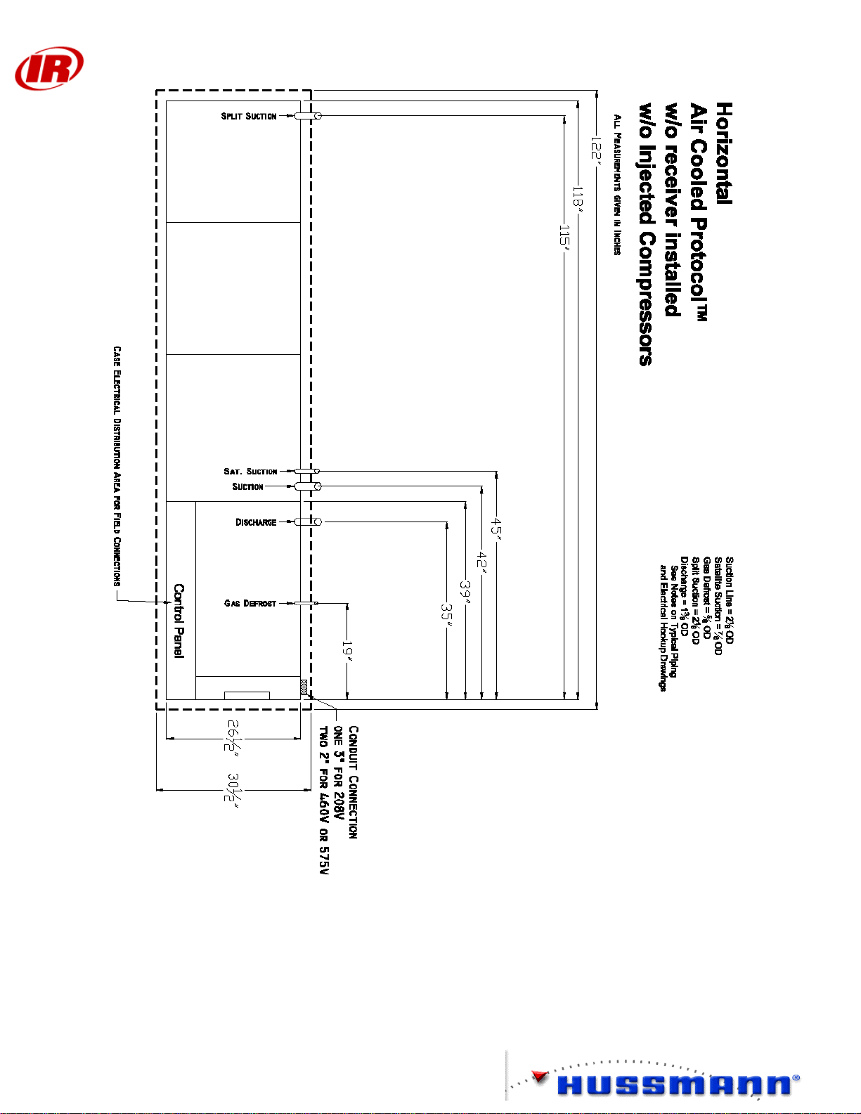
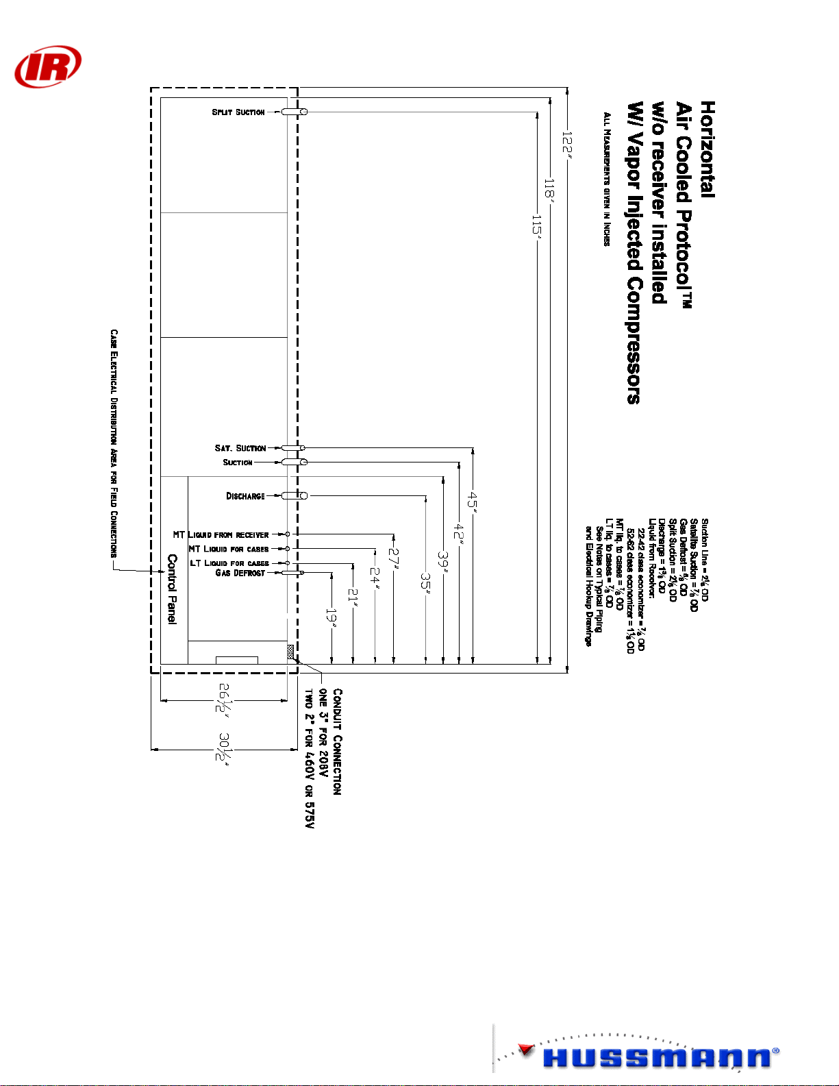
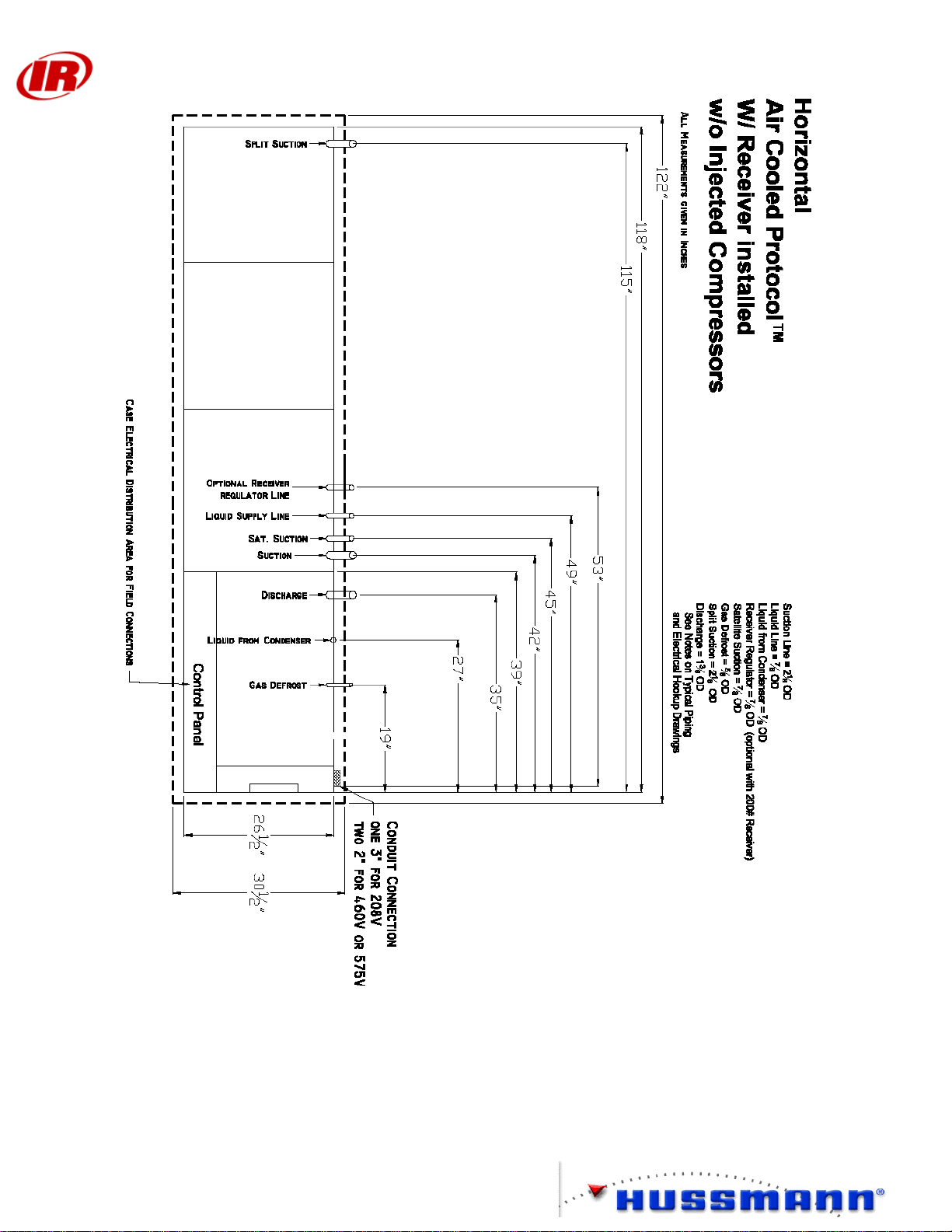
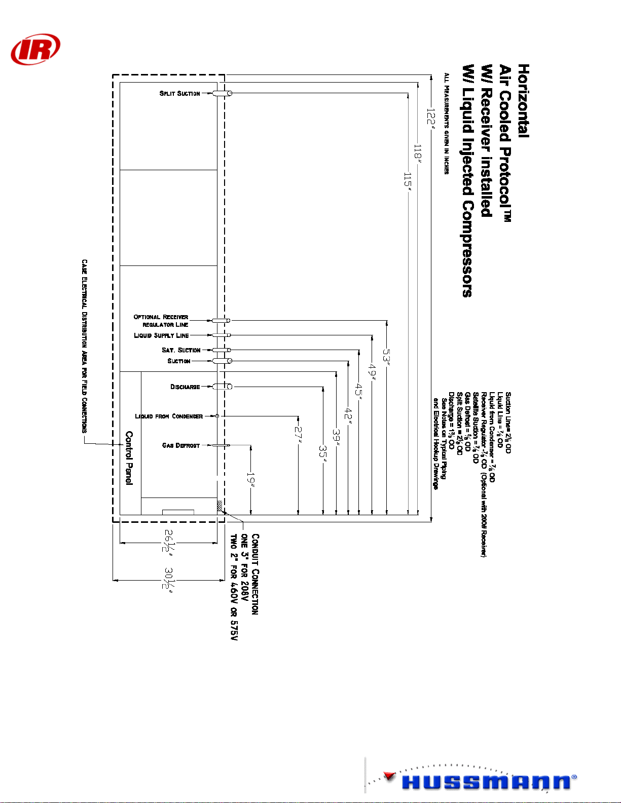
Horizontal Units............................................................................................................ 20
Proto_Aire Units........................................................................................................... 33
REFRIGERATION PIPING......................................................................... 40
Overview....................................................................................................................... 40
Refrigeration Line Piping ............................................................................................. 40
Refrigeration Cycle....................................................................................................... 41
Protocol™ with 3-Pipe Gas Defrost ............................................................................. 42
Protocol™ with Heat Reclaim...................................................................................... 43
Protocol™ with Split Suction....................................................................................... 44
Oil Cycle....................................................................................................................... 45
Liquid Injection............................................................................................................. 46
Vapor Injection ............................................................................................................. 47
Field Piping................................................................................................................... 48
Water Loop Piping........................................................................................ 49
Overview....................................................................................................................... 49
Water Loop Guidelines................................................................................................. 49
Pipe Connections ...................................................................................................... 49
Isolation Valves ........................................................................................................ 49
Strainers .................................................................................................................... 49
Air Vent Valves ........................................................................................................ 50
Tie-Ins to Supply Headers ........................................................................................ 50
Pipe Supports............................................................................................................ 50
Exposure to Direct Sunlight...................................................................................... 50
Leak Check ............................................................................................................... 50
Cleaning and Flushing .............................................................................................. 50
Filling........................................................................................................................ 50
Balance Valve Adjustment ....................................................................................... 51
Presetting The Flow Control (Balancing) Valve .......................................................... 51
Balancing the Water Loop........................................................................................ 52
Balancing the Water Loop for Direct Return Piping................................................ 52
Page 3

Protocol™ Installation and
Service Manual
Balancing the Water Flow for Each Protocol™....................................................... 53
Balancing the System for Piping Head Loss............................................................. 55
Presetting the Degree of Closure .............................................................................. 57
Electrical....................................................................................................... 59
Field Wiring.................................................................................................................. 59
Main Power Wiring....................................................................................................... 65
208V Two Wide Protocol™..................................................................................... 65
208V 5 or 6 Compressor Protocol™ ........................................................................ 66
460V Two Wide Protocol™..................................................................................... 67
460V 5 or 6 Compressor Protocol™ ........................................................................ 68
460V Two Wide Protocol with Factory installed transformer.................................. 69
460V Two Wide Protocol™ with Field supplied transformer.................................. 70
460V 5 or 6 Compressor Protocol™ with Field supplied transformer..................... 71
600V Two Wide Protocol™..................................................................................... 72
600V 5 or 6 Compressor Protocol™ ........................................................................ 73
600V Two Wide Protocol™ with Field supplied transformer.................................. 74
Terminal Connections................................................................................................... 75
120V Circuit Logic....................................................................................................... 75
24V Circuits.................................................................................................................. 75
Electronic Oil Level Control......................................................................................... 75
Satellite Short Cycle Control Relay.............................................................................. 76
Control and Compressor Wiring................................................................................... 77
PCS without Vapor Wiring....................................................................................... 77
PCS with Vapor Wiring............................................................................................ 78
CPC, Danfoss, Comtrol without Vapor Wiring........................................................ 79
CPC, Danfoss, Comtrol with Vapor Wiring............................................................. 80
Controller Wiring.......................................................................................................... 81
PCS ........................................................................................................................... 81
CPC........................................................................................................................... 82
CPC Einstein............................................................................................................. 83
Danfoss ..................................................................................................................... 84
Comtrol..................................................................................................................... 85
Liquid Injection............................................................................................................. 86
Vapor Injection ............................................................................................................. 86
Refrigeration Circuit Control.................................................................................... 88
Off time Sequence of Operation............................................................................... 88
Hot Gas ..................................................................................................................... 89
Electric Defrost......................................................................................................... 89
Special Case of Heat Reclaim with Hot Gas Defrost ............................................... 90
Lighting Control............................................................................................................ 91
Unit Cooler Fan Wiring................................................................................................ 92
Protocol™ Remote Condenser Fan Wiring.................................................................. 93
POWERLINK™ Operation.......................................................................................... 97
Wiring Optional Auto Dialer and In-Store Alarm........................................................ 98
Startup........................................................................................................... 99
Startup........................................................................................................................... 99
Electronic Oil Level Control....................................................................................... 103
Page 4

Protocol™ Installation and
Service Manual
Auxiliary Systems....................................................................................................... 104
3-Pipe Gas Defrost...................................................................................................... 105
Electric Defrost........................................................................................................... 105
Offtime Defrost........................................................................................................... 106
Sensor Applications.................................................................................................... 106
Suction Pressure Sensor.......................................................................................... 106
Suction Pressure Input ............................................................................................ 106
Temperature Input................................................................................................... 107
All Additional Pressure/Temperature Inputs.......................................................... 107
Programming the Optional In-store Alarm and Auto Dialer...................................... 107
Troubleshooting Guide............................................................................... 108
Electrical Questions.................................................................................................... 109
Trouble Shooting Alarms............................................................................................ 113
Service......................................................................................................................... 115
Recommended Maintenance....................................................................................... 116
Sample Protocol™ Checklist.................................................................................. 118
Page 5

Protocol™ Installation and
Service Manual
Installation
Overview
This section is limited to the information needed to set the Protocol™ Unit. Auxiliary
equipment information is found in the sections devoted to them or in the manuals
accompanying them.
Related information is contained in Protocol™ Planning Data and the Pumping Station
Planning Data.
Shipping Damage
All equipment should be thoroughly examined for shipping damage before and while
unloading.
This equipment has been carefully inspected at our factory, and the carrier has assumed
responsibility for safe arrival. If damaged, either apparent or concealed, the claim must be
made to the carrier.
Apparent Loss or Damage
If there is an obvious loss or damage, it must be noted on the freight bill or express receipt
and signed by the carrier’s agent; otherwise, carrier may refuse claim. The carrier will
supply the necessary claim forms.
Concealed Loss or Damage
When loss or damage is not apparent until after equipment is uncrated, a claim for
concealed damage is made. Upon discovering damage, make request in writing to carrier
for inspection within 15 days and retain all packing. The carrier will supply inspection
report and required claim forms.
On Site Damage Control
The Protocol™ is shipped on skids with panels installed. Remove panels to access lifting
points on frame. Do not attempt to move the unit from the skids without first removing the
panels.
1
Page 6
Protocol™ Installation and
Service Manual
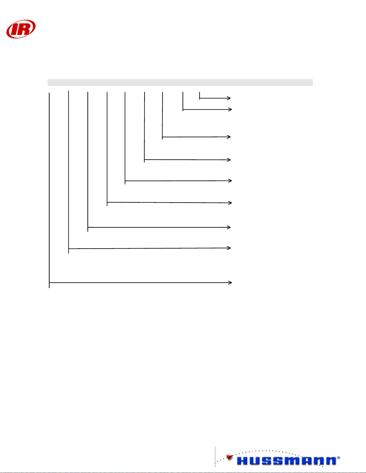
PROTOCOL UNIT NOMENCLATURE
The model numbers of PROTOCOL units are shown on the legend in modular form. The nomenclature is
interpreted as follows:
O P A V 1 3 P K - XX XX XX XX
COMPRESSOR CODES
VOLTAGE K=208/230;
M= 460/3/60; P= 575/3/60;
U= 380/3/50
REFRIGERANT J=134a;
P=R507; V=R22; S=404a
# OF PARALLEL
COMPRESSORS
# OF SATELLITE
COMPRESSORS
FRAME TYPE
V=Vertical
H=Horizontal
A= AIR COOLED
W= WATER COOLED
P=PROTOCOL
L=LOW PROFILE
H=HIGH EFFICIENCY
PROTOCOL
PROTO-AIRE DESIGNATION
The unit nomenclature is part of the UL code requirements and must be included on the legend as well as the
data plate for each unit
2
Page 7

Protocol™ Installation and
Service Manual
Dimensions and Weights
Vertical L H D Weight
Nomenclature (in.) (in.) (in.) (lb)
17FR 30.5 80 30.5 1200
18FR 43.5 80 30.5 1500
Horizontal L H D Weight
Nomenclature (in.) (in.) (in.) (lb)
20FR, 13FR, 29ZX 122 32 30.5 1700
32FX, 33FX, 34FX 122 32 30.5 1900
Proto-Aire™ L H D Weight
Nomenclature (in.) (in.) (in.) (lb)
3 & 4 fan 128 56.5 42 2800
6 fan (super) 185 56.5 42 3700
Note: Maximum weight includes sound coating and refrigerant.
Receiver Capacities are based on 80% liquid fill at 105 °F.
Vertical – 55 lb
Horizontal– 72 lb (Standard) 200# option
3 & 4 Fan Proto-Aire™ - 72 lb (Standard) 200# option
6 Fan Proto-Aire™ - 145 lb (Standard) 200# option
Field Supplied and Installed Water Components
The Protocol™ comes equipped with a flow control/shutoff valve for servicing the plate
heat exchanger. All other water loop components must be field supplied and installed. A
16-20 mesh strainer (1 mm) is required immediately upstream of each Protocol™.
Accessibility
All Standard Control Panel Doors require 40 inches clearance. Oversized Control Panel
Doors require 48 inches clearance. Vertical Protocol™ units must be serviceable from the
front and top of the unit. Access to either side is also recommended. Horizontal
Protocol™ units must be serviceable from three sides, the front and right side as well as the
top or back as viewed facing the removable panels. A minimum of 40 inches clearance is
recommended.
3
Page 8
Protocol™ Installation and
Service Manual
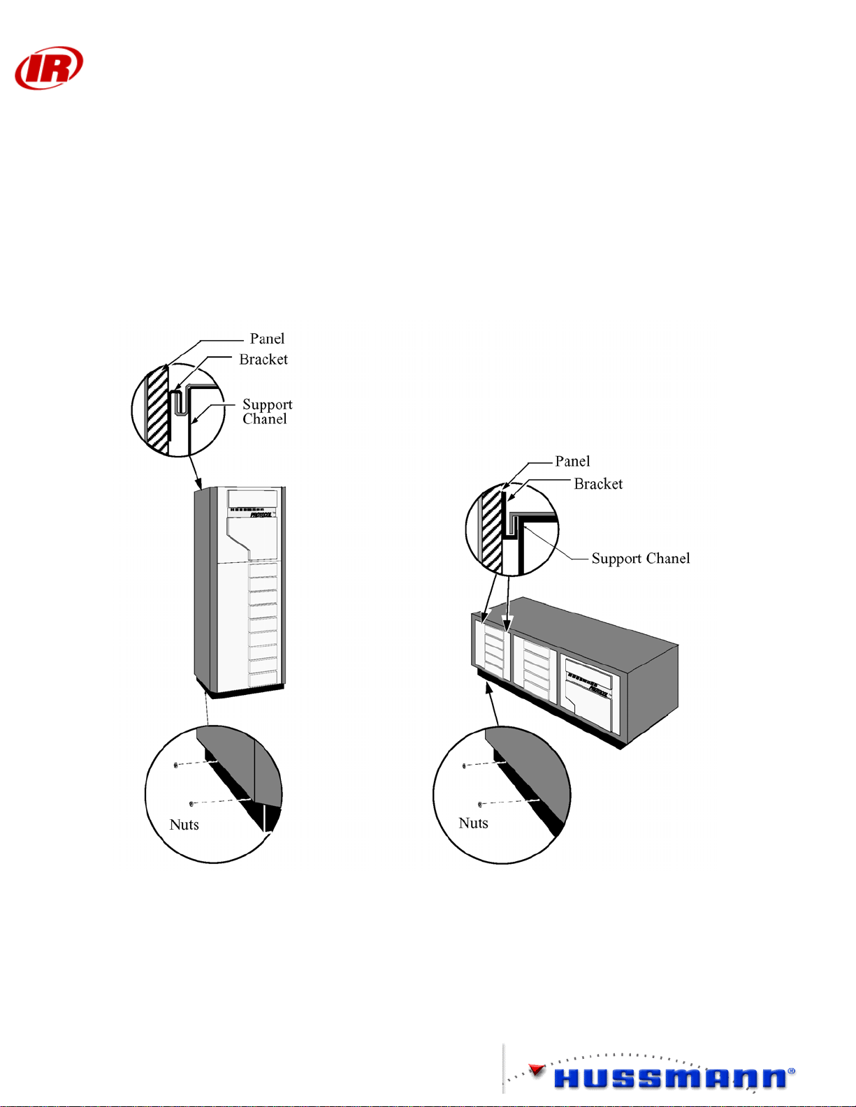
Panel Removal
Vertical Units
At the top, a bracket in a channel supports each panel. At the bottom, each panel is held in
place by two nuts. Remove the nuts at the bottom of the panel, then lift up and out.
Horizontal Units
At the top, a bracket in a channel supports each panel. At the bottom, each panel rests on
two studs and is held in place by nuts. Remove the nuts at the bottom of the panel, then
slide the panel out at the bottom and down.
4
Page 9
Protocol™ Installation and
Service Manual
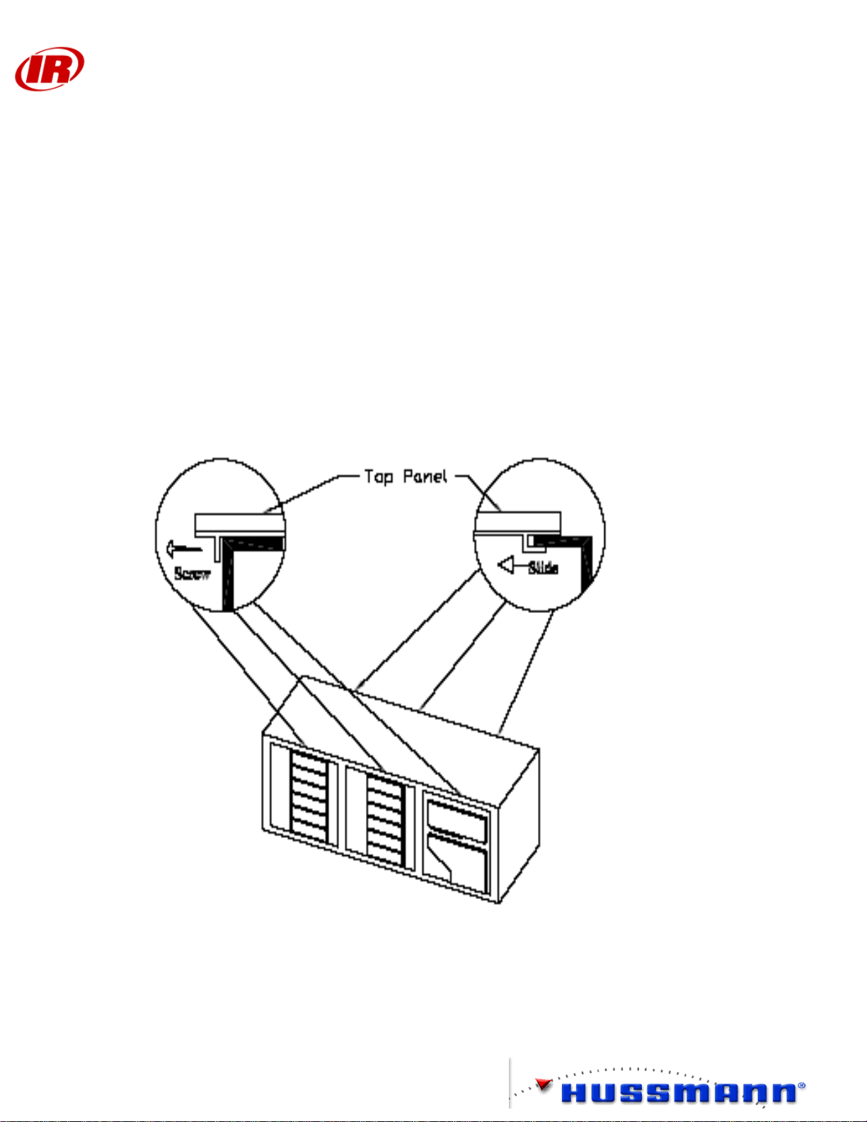
Horizontal Units – Top Removal
To remove the top assembly, first remove the front panels. Then remove the bracket screw
at top center of each panel opening and above the control panel. Slide the top assembly
forward until the back clips disengage. Lift the top off. Reverse procedure to install.
For some under-table applications, it may be desirable to remove the finished top panel to
reduce the Protocol™ unit’s height by two inches. To separate the top panel assembly,
remove it and take out the screws holding the finished top panel to the sub-panel. The subpanel MUST be installed, even when the finished top is not used.
5
Page 10

Protocol™ Installation and
Service Manual
Rigging and Hoisting
The installer is responsible for ensuring that the equipment used to move the Protocol™ is
operated within its limits. Under no circumstances should the top of the unit or the outer
panels be used for lifting or moving the unit. For strap rigging, run the straps under the top
level of compressor mounting channel.
Vibration Pads
Vibration Isolation Pads are supplied with each Protocol™ unit. To adjust for slightly
uneven floors, place 16 gauge galvanized steel shims between the vibration pads and the
floor (shims must be field supplied). One vibration pad is installed under each upright
channel. Vertical units use four pads. Horizontal units use 8 to 10 pads.
6
Page 11
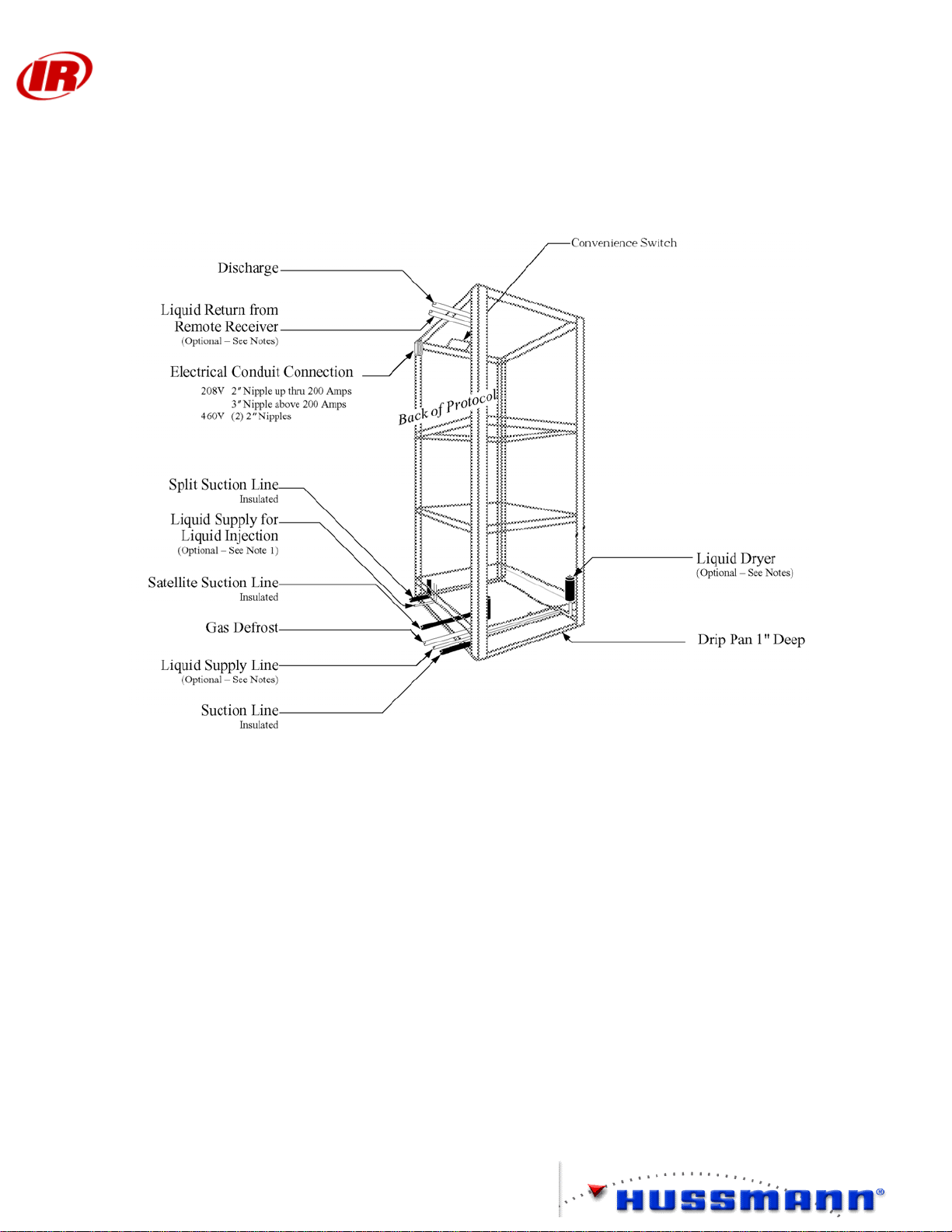
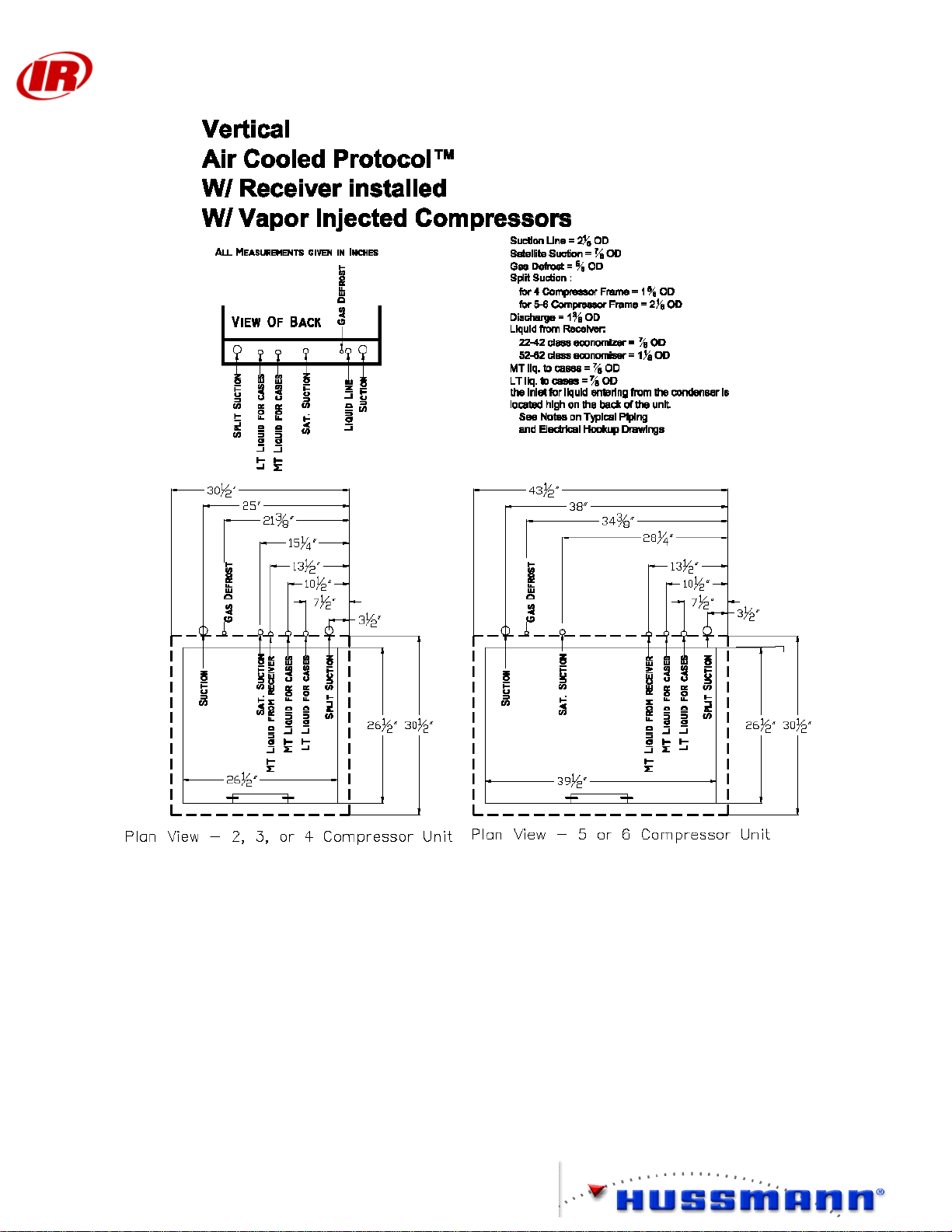
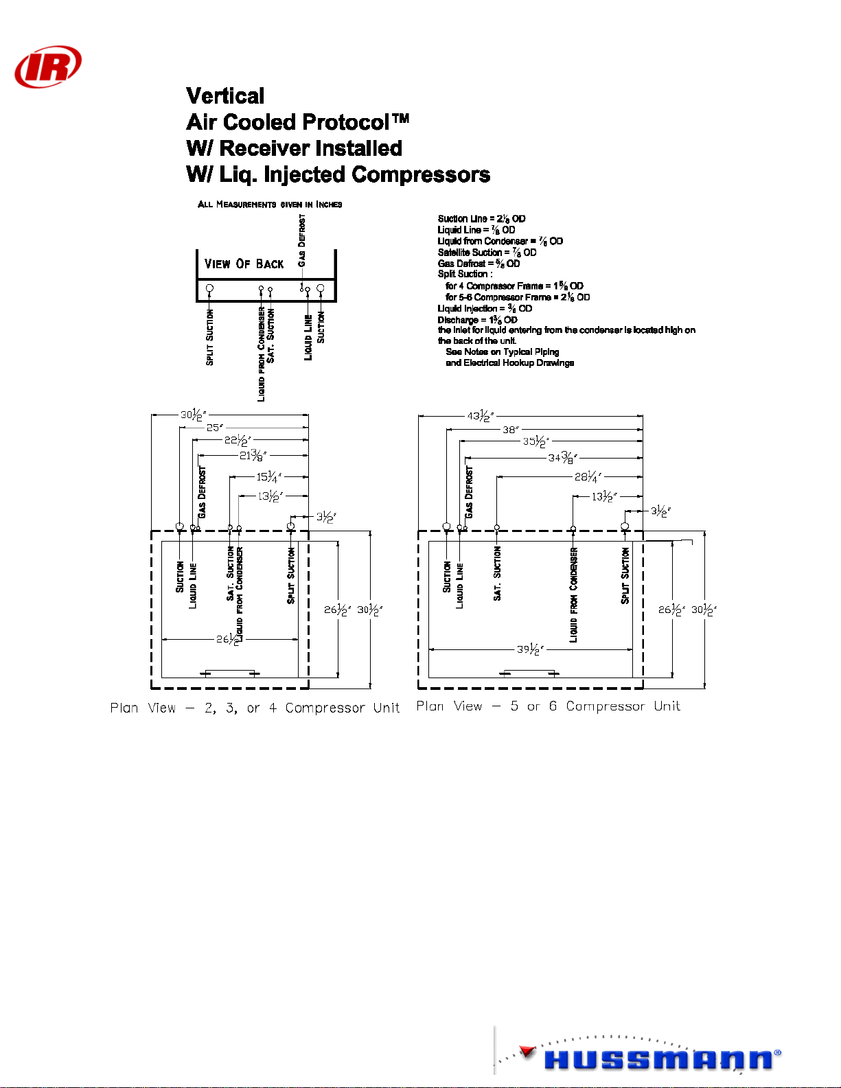
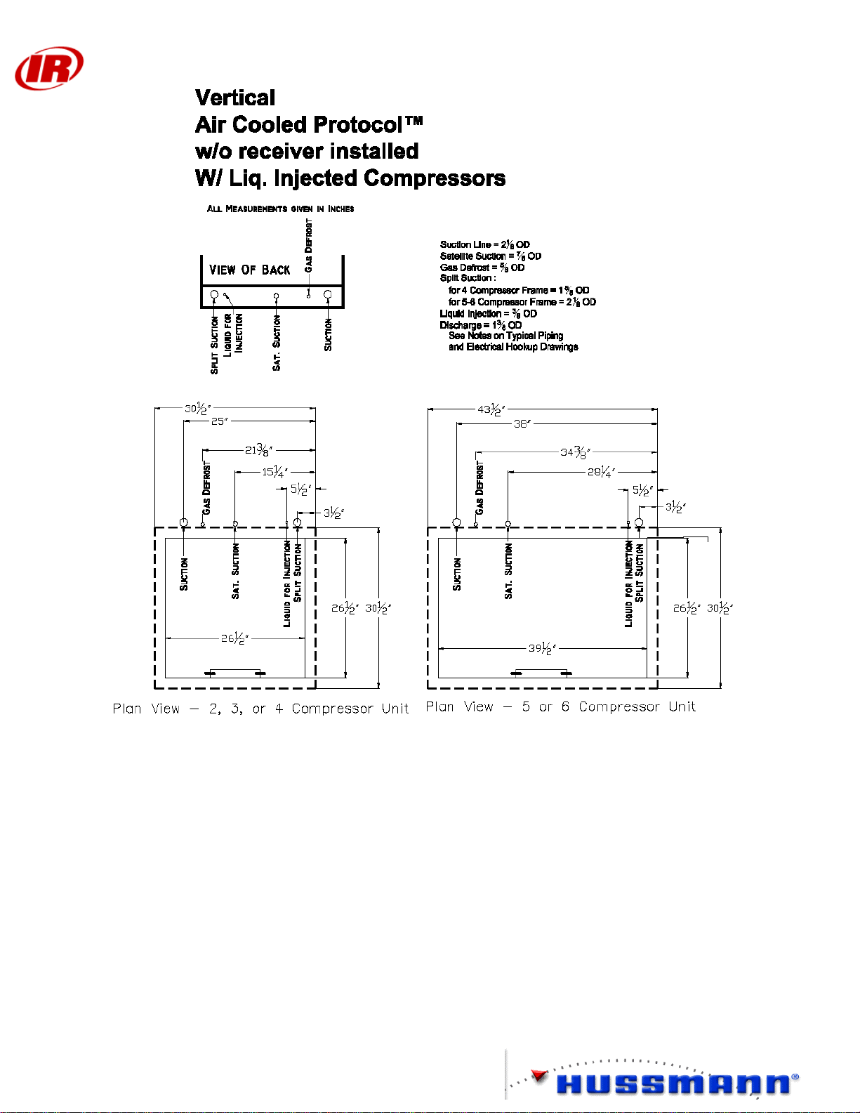
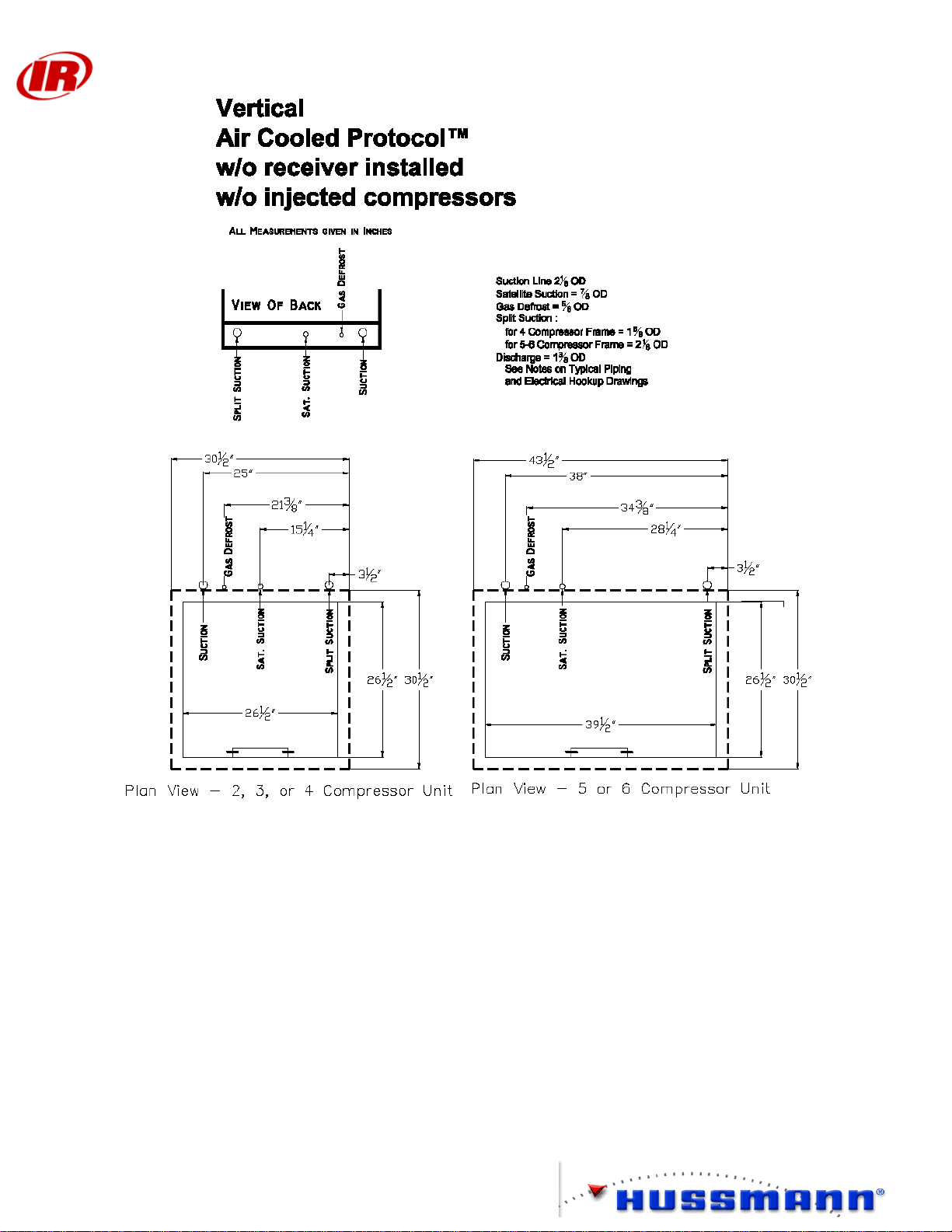
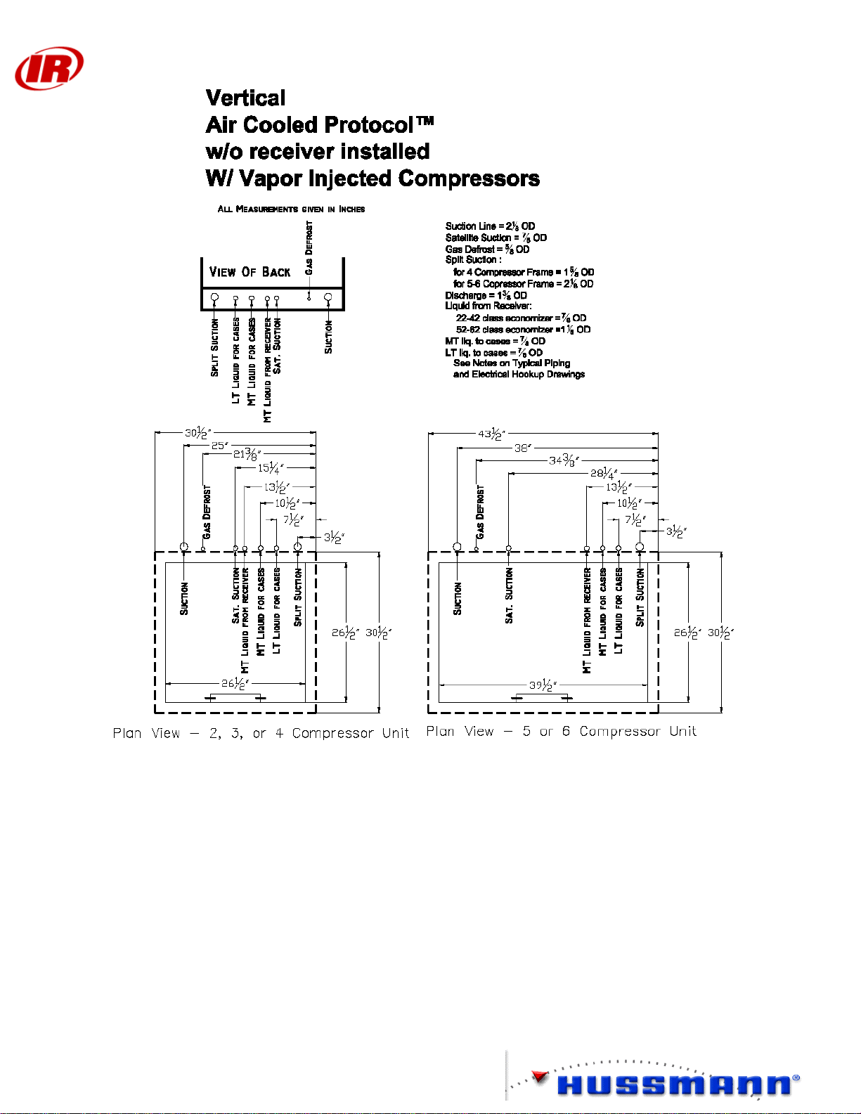
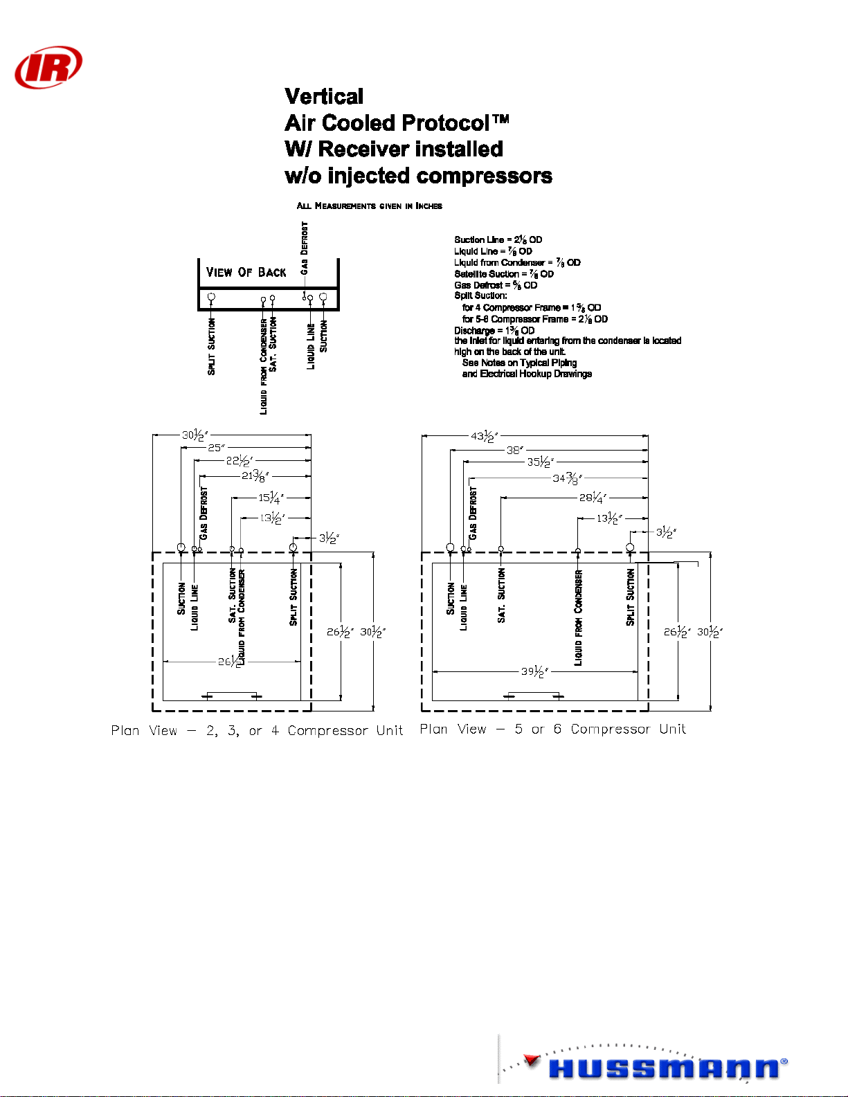
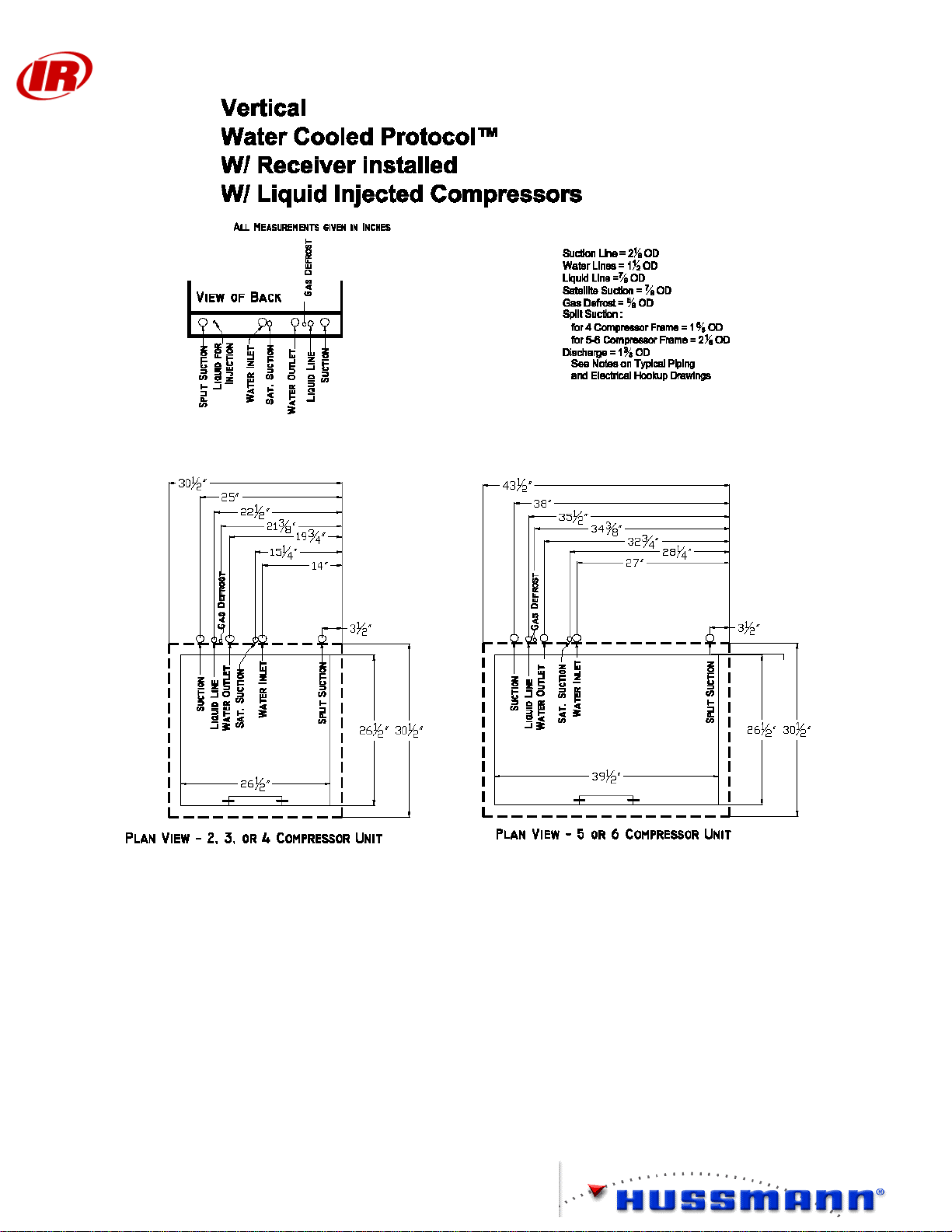
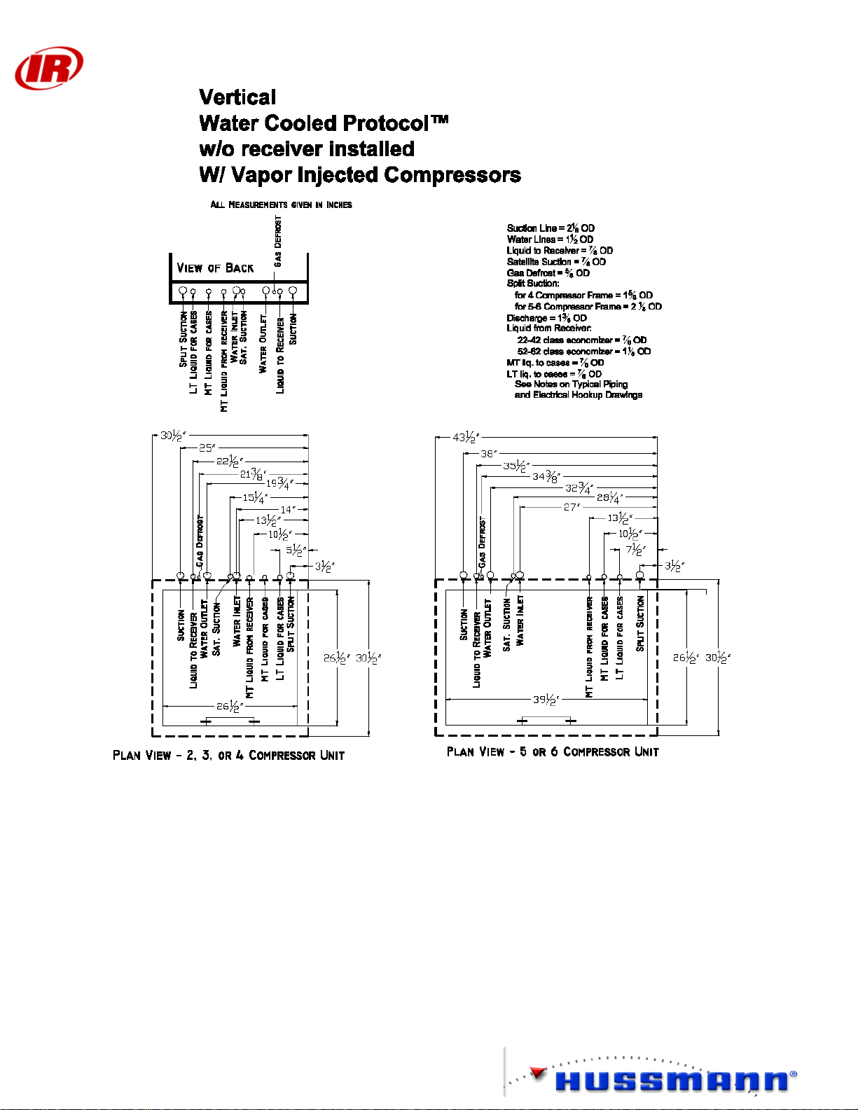
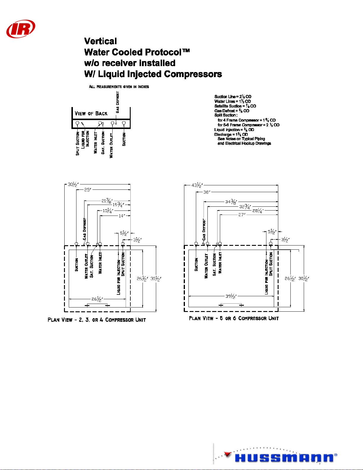
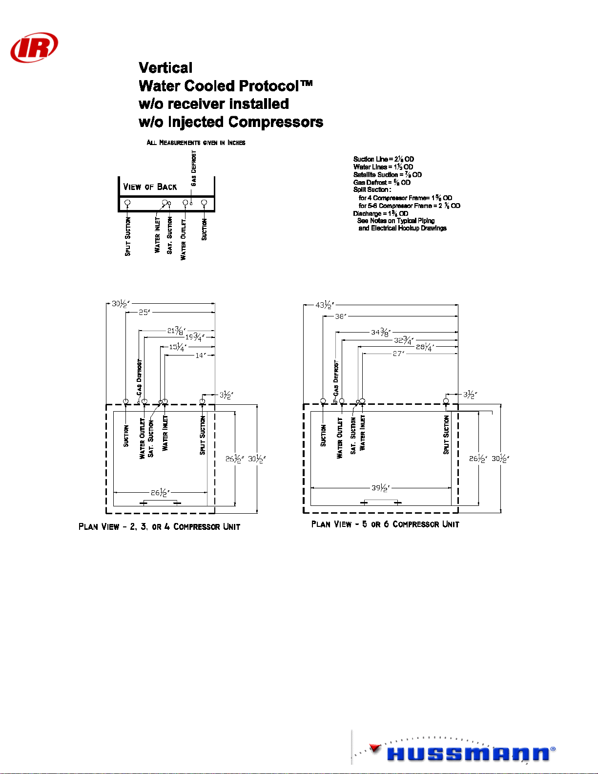
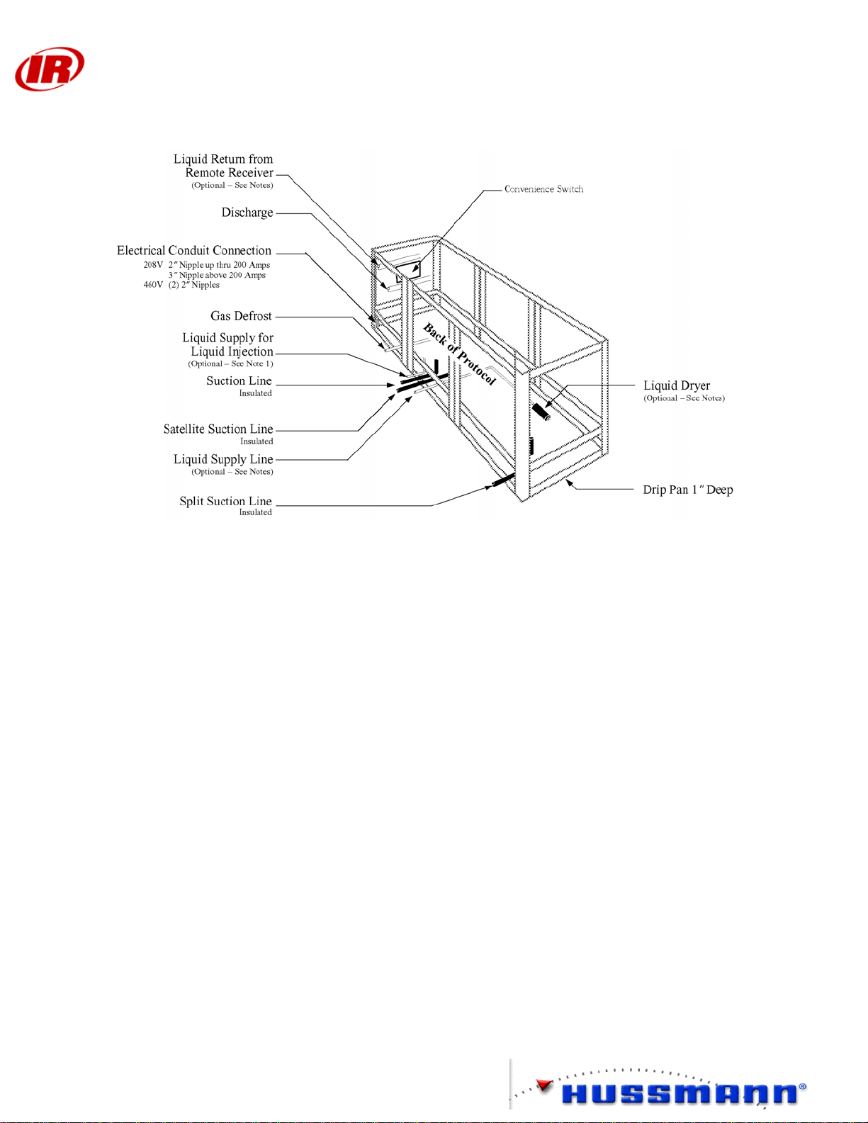
TYPICAL PIPING & ELECTRICAL HOOKUP
Vertical Units
Protocol™ Installation and
Service Manual
7
Page 12
Protocol™ Installation and
Service Manual
8
Page 13
Protocol™ Installation and
Service Manual
9
Page 14
Protocol™ Installation and
Service Manual
10
Page 15
Protocol™ Installation and
Service Manual
11
Page 16
Protocol™ Installation and
Service Manual
12
Page 17
Protocol™ Installation and
Service Manual
13
Page 18

Protocol™ Installation and
Service Manual
14
Page 19
Protocol™ Installation and
Service Manual
15
Page 20
Protocol™ Installation and
Service Manual
16
Page 21
Protocol™ Installation and
Service Manual
17
Page 22
Protocol™ Installation and
Service Manual
18
Page 23

Protocol™ Installation and
Service Manual
19
Page 24
Horizontal Units
Protocol™ Installation and
Service Manual
20
Page 25
Protocol™ Installation and
Service Manual
21
Page 26
Protocol™ Installation and
Service Manual
22
Page 27

Protocol™ Installation and
Service Manual
23
Page 28
Protocol™ Installation and
Service Manual
24
Page 29
Protocol™ Installation and
Service Manual
25
Page 30

Protocol™ Installation and
Service Manual
26
Page 31

Protocol™ Installation and
Service Manual
27
Page 32

Protocol™ Installation and
Service Manual
28
Page 33

Protocol™ Installation and
Service Manual
29
Page 34

Protocol™ Installation and
Service Manual
30
Page 35

Protocol™ Installation and
Service Manual
31
Page 36

Protocol™ Installation and
Service Manual
32
Page 37

Proto_Aire Units
Protocol™ Installation and
Service Manual
33
Page 38

Protocol™ Installation and
Service Manual
34
Page 39

Protocol™ Installation and
Service Manual
35
Page 40

Protocol™ Installation and
Service Manual
36
Page 41

Protocol™ Installation and
Service Manual
37
Page 42

Protocol™ Installation and
Service Manual
38
Page 43

Protocol™ Installation and
Service Manual
39
Page 44

Protocol™ Installation and
Service Manual
REFRIGERATION PIPING
Important: Since Hussmann has no direct control over the installation,
providing freeze-burst protection is the responsibility of the
installing contractor. Refer to Page 48
Always use a pressure regulator with a nitrogen tank. Do not exceed 2 pisg and
vent lines when brazing. Do not exceed 350 psig for leak testing high side. Do not
exceed 150 psig for leak testing low side.
Always recapture test charge in approved recovery vessel for recycling.
The Water Loop should be tested for leaks using pressurized water.
DO NOT exceed 75 psig at the lowest point in the piping.
Overview
This section details the major refrigeration components and their locations in each piping
system.
Refrigeration Line Piping
Use only clean, dehydrated, sealed refrigeration grade copper tubing. Use dry nitrogen in
the tubing during brazing to prevent the formation of copper oxide. All joints should be
made with silver alloy brazing material, and use 35% silver solder for dissimilar metals.
Liquid and suction lines must be free to expand and contract independently of each other.
Do not clamp or solder them together. Run supports must allow tubing to expand and
contract freely. Do not exceed 100 feet without a change of direction or an offset. Plan
proper pitching, expansion allowance, and P-traps at the base of all suction risers. Use long
radius elbows to reduce flow resistance and breakage. Avoid completely the use of 45°
elbows. Install service valves at several locations for ease of maintenance and reduction of
service costs. These must be UL approved for 450 psig minimum working pressure.
All Protocol™ units have one-inch drip pan at the bottom of the unit. DO NOT run piping
through the bottom of this pan.
Return Gas Superheat
Return gas superheat should be 10 to 30 °F on all units.
Suction Line
1. Install a downward slope in direction of flow. A P-trap is required for all vertical
risers.
2. Line may be reduced by one size after first third of case load and again after the
second third. Do not reduce below evaporator connection size.
3. Suction returns from evaporators must enter at the top of the line.
40
Page 45

Protocol™ Installation and
Service Manual
Liquid Line
1. Take-offs to evaporators must exit the bottom of the liquid line. Provide an
expansion loop for each evaporator take-off (minimum 3-inch diameter).
2. Offtime and Electric Defrost may be reduced by one size after one half the case
load. Do not reduce below evaporator connection size.
Refrigeration Cycle
Oil Return System Not shown
Beginning with Compressors, refrigerant vapor is compressed into the Discharge Header.
The Turba-Shed oil separator effectively divides the refrigerant from the lubricant in the
system. The lubricant is then returned to the compressors. The Condenser dissipates the
unwanted heat from the refrigerant into either a water/ glycol, or, air condenser depending
on the type used. The receiver acts as a vapor trap and supplies the Liquid Line with
quality liquid refrigerant. A Liquid Line Filter/Drier removes water and other
contaminants from the refrigerant. The liquid branch line supplies liquid refrigerant to the
Thermostatic Expansion Valve (TXV), which in turn feed refrigerant to the cases
(evaporator coils). These coils pick up heat from the product stored in the cases. A
Suction Filter removes system contaminants from return vapor, which is factory supplied
but field installed. It is also a good idea to install isolation valves for ease of service. The
oil return system is not shown in the following illustration.
Liquid Line
Case
Filter / Drier
Sight Glass
Receiver
Condenser
Case
Liquid Branch Line
Case
Case
Suction Line
Filter
Suction Branch Line
Discharge Header
Compressors
Suction Header
Turba-Shed
Oil Separator
41
Page 46

Protocol™ Installation and
Service Manual
Protocol™ with 3-Pipe Gas Defrost
Oil Return System Not shown
When 3-pipe gas defrost is used, hot gas is piped from the discharge line, after the oil
separator, to the cases. Solenoid valves are placed in both the suction and hot gas line so
that each system can be tuned on or off by the controller. Place a bypass line, with a check
valve ensuring that flow during defrost can bypass the TXV. A pressure differential
solenoid valve needs to be installed in the main liquid line to insure proper flow during
defrost. The pressure differential solenoid valve is factory installed in a vertical or
horizontal Protocol™. Ensure that during defrost no more than 45 lbs or 20% of the total
load is in defrost at any given time.
Liquid Line
Pressure
Differential
Solenoid Valve
Filter / Drier
Sight Glass
Receiver
Condenser
Liquid Branch Line
Case
Case
Case
Case
S
S
S
S
S
S
S
S
Suction Line
Filter
Hot Gas Line
Discharge Header
Compressors
Suction Header
Turba-Shed
Oil Separator
Check Valve
S
Solenoid Valve
42
Page 47

Protocol™ Installation and
Service Manual
Protocol™ with Heat Reclaim
Oil Return System Not shown
When heat reclaim (for water or air) is used with the Protocol™ a 3-Way Heat Reclaim
Valve should be installed after the oil separator. A bleed line should be installed from the
heat reclaim valve to the angle valve found in the suction header. A check valve is
installed in the heat reclaim return loop. This check valve ensures that back flow through
the heat reclaim coil is eliminated when heat reclaim is not used. Refer to specific
manufacturers guidelines for sizing reclaim coils. In the case of water heat reclaim, a 10#
check valve should be used to bypass the water tank in the case that the pressure drop
across the tank become excessive.
Liquid Line
Case
Filter / Drier
Sight Glass
Receiver
Condenser
Liquid Branch Line
Case
Case
Case
Suction
Filter
Suction Branch Line
Angle Valve
Heat
Reclaim
Coil
Discharge Header
Compressors
Suction Header
Check Valve
3-Way Heat Reclaim Valve
Turba-Shed
Oil Separator
Bleed Line
43
Page 48

Protocol™ Installation and
Service Manual
Protocol™ with Split Suction
Oil Return System Not shown
Split suction is used when two temperatures are required from the same Protocol™ unit. The use of split
suction allows for greater efficiency due to the fact that the compressors are operating closer to the desired
suction temperature.
Liquid Line
Filter / Drier
Receiver
Condenser
Liquid Branch Line
Case
Case
Case
Case
Suction
Filters
Suction Branch Line
Sight Glass
Discharge Header
Compressors
Turba-Shed
Oil Separator
Split Suction Headers
44
Page 49

Oil
Regulator
Protocol™ Installation and
Service Manual
Oil Cycle
Discharge refrigerant carries droplets of oil from the compressor’s outlet. The Turba-Shed
separates the oil from the refrigerant. The oil is stored in the Turba-shed until needed. The
oil returns to the system through the high-pressure line and oil filter.
The oil filter removes impurities from the oil. The high-pressure oil is distributed to the
electronic oil level control, which feeds oil into the compressor through a solenoid valve.
Electronic oil regulators monitor oil levels. The units are powered by a 24V power supply.
When the oil level in the compressor drops below ½ sightglass, the fill light comes on, and
the oil solenoid is energized. If after 90 seconds the oil level does not rise above ½
sightglass, the unit opens the compressor control circuit. If oil becomes available, the
electronic oil level control will automatically re-set and the compressor will resume
operation.
Discharge Header
Turba-Shed
Oil Separator
Oil Header
Suction Header
Oil
Filter
45
Page 50

Protocol™ Installation and
Service Manual
Liquid Injection
When operating at high compression ratios, injecting liquid partway through the
compression process is a method of cooling the scroll compressor. Hussmann applies
liquid injection on all units operating below 0 °F evaporating temperature, with the
exception of the Low-temp high efficiency Protocol™. Each compressor has its own
shutoff valve, injection solenoid valve, and supply hose. When the compressor is off, the
solenoid valve is de-energized via a current sensing relay mounted at the compressor
contactor.
Note: On units with remote air-cooled condensers, liquid refrigerant must be piped to the
liquid injection stub-out at the back of the Protocol™ unit.
Liquid Line
Filter / Drier
Receiver
Condenser
Liquid Branch Line
Case
Case
Case
Case
Suction Line
Filter
Sight Glass
Suction Branch Line
S
Liquid Injection
Header
S
Compressors
S
S
Turba-Shed
Oil Separator
Suction Header
46
Page 51

Protocol™ Installation and
Service Manual
Vapor Injection
Another method of cooling the scroll compressor is to use vapor injection. Vapor Injection
takes a small portion of liquid refrigerant from the main liquid line and runs it through a
thermostatic expansion valve and a heat exchanger, which helps to ensure vapor is sent to
the compressor as well as sub-cooling the main refrigerant before it goes to the TXV and
evaporator in the case.
Liquid Branch Line
Case
Case
Case
Case
Suction Line
Filter
Heat
Exchanger
Suction Branch Line
S
Liquid Line
F ilte r / Drie r
S Port
Sight Glass
V apor Injection
H eader
S
Receiver
S
S
Condenser
Tu rba-Shed
Compressors
Suction H eader
47
Oil Separator
Page 52

Protocol™ Installation and
Field Piping
Field Fabricated Headers are not required with Protocol™ Installations.
Example of Improper Field Piping
Protocol™
Produce Cases
Produce Islands
Produce Room
Service Manual
Produce Cases
Produce Islands
Example of Proper Field Piping
Protocol™
Produce Cases
Produce Room
Produce Islands
Produce Cases
Produce Islands
48
Page 53

Protocol™ Installation and
Service Manual
Water Loop Piping
Important: Since Hussmann has no direct control over the installation, providing
freeze-burst protection is the responsibility of the installing contractor. It is
mandatory that glycol be added to the water loop before startup to prevent
freezing. Use only non-ferrous metal or PVC for water loop piping.
The Water Loop should be tested for leaks using pressurized water.
DO NOT exceed 75 psig
Overview
This section details major water loop components, and their locations in the piping system.
Water Loop Guidelines
Pipe Connections
PVC Plastic pipe should be solvent welded (glued) together as described on the glue can.
Pipe Fittings must be clean and dry.
Cut Pipe with a guillotine type cutter to get a clean, square cut; remove any burrs.
Use Purple Primer on both pipe and fitting before gluing.
Apply glue to both pipe and fitting and join with a twisting motion.
Hold joint together for approximately 30 seconds to allow glue to set.
Allow to dry for 24 hours before putting in to service.
Where it is necessary to connect plastic and metal pipe. DO NOT USE A THREADED
CONNECTION. A compression type fitting should be used. For larger pipe sizes, a
flanged connection may be used.
Isolation Valves
Install isolation valves at inlet and outlet of each Protocol™ unit.
It is good practice to include isolation valves at several locations throughout the piping.
For example valves should be used where branches tie into main supply and return lines.
PVC plastic ball valves may be used.
Strainers
Use a 16-mesh strainer at inlet of each Protocol™ unit. Position isolation valves so that
this strainer can be opened for cleaning.
49
Page 54

Protocol™ Installation and
Service Manual
Air Vent Valves
Manual air vent valves are recommended. Air vent valves should be located at piping high
points where air will tend to collect. Momentarily open these vents and release trapped air
a few times during startup.
Tie-Ins to Supply Headers
Branch supply pipes SHOULD NOT tie into the bottom of main supply pipes. Always tie
into top of a main supply pipe; that is, the “T” fitting should point UP, NOT DOWN.
Pipe Supports
Pipe support should be provided as follows:
Nominal Pipe Size,
inches
1.0 4.5 3.5
1.5 5.0 3.5
2.0 5.0 4.0
3.0 6.0 4.5
4.0 6.5 5.0
6.0 7.5 6.0
Do not clamp supports tightly – this restricts axial movement of the pipe. Supports should
provide a smooth bearing surface that conforms to the bottom of the pipe, and should be a
minimum of 2 inches wide.
Exposure to Direct Sunlight
Piping that will be exposed to direct sunlight should be shaded or covered. A thin layer of
insulation is adequate for this.
Leak Check
Check for leaks in the piping before startup by filling with pressurized water at 50 psig.
Cleaning and Flushing
The pipe loop should be cleaned before the system is put into service. Fill the closed loop
with a solution of 1% trisodium phosphate and (99%) water, by weight.
Circulate the detergent/water solution for 24 hours.
Drain the loop and refill with fresh water. Circulate for at least 3 hours.
Drain and refill again. Repeat until all phosphate is gone.
Filling
The water loop MUST have adequate corrosion protection. In most situations, using fully
inhibited, industrial grade ethylene glycol or propylene glycol 30% by volume with water
Distance Between Supports,
feet
Schedule 40 Pipe @ 100 °F
Distance Between Supports,
feet
Schedule 80 Pipe @ 120 °F
50
Page 55

Protocol™ Installation and
Service Manual
can provide corrosion protection. For most installations, 30% glycol by volume will also
provide BURST protection to –20 °F.
If the store location has particularly hard water, with a total hardness greater than 100 ppm,
the water used to fill the loop should be softened or distilled. Local water treatment
vendors can provide information on local water quality.
If any Protocol™ unit has reverse cycle gas defrost, at least 30% glycol by volume MUST
be used to prevent condenser freezing.
Use only industrial grade, fully inhibited ethylene or propylene glycol such as Dow
Chemical’s Dowtherm SR-1 or Dowfrost. Consult local regulations as to which type –
ethylene or propylene – to use. Propylene glycol is generally considered non-toxic, while
ethylene glycol is somewhat toxic. DO NOT USE AUTOMOTIVE GRADE GLYCOL.
Use a refractometer to check the glycol concentration at least once a year.
The pumping station has a low fluid pressure switch set at roughly 10 to 20 psig, which
should be tied into an alarm. It is good practice to test the operation of this switch at least
once a year.
Balance Valve Adjustment
A flow balancing valve is located inside each Protocol™. These valves should be set at
startup using the following procedure.
Presetting The Flow Control (Balancing) Valve
(Bell & Grossett 1½ inch Circuit Setter)
51
Page 56

Protocol™ Installation and
Service Manual
Balancing the Water Loop
.
Balancing the Water Loop for Direct Return Piping
Several factors must be accounted for when balancing the water loop of a Protocol™
installation using direct return piping. Two major factors stand out:
1 – Balancing to attain the correct water flow for each Protocol™; and
2 – Balancing the system for Piping Head Loss.
Since these factors have nearly unlimited combinations, finding the appropriate setting for
each combination is unrealistic. However, if these factors are separated, their effect on the
system can easily be defined.
52
Page 57

Protocol™ Installation and
Service Manual
Balancing the Water Flow for Each Protocol™
If the store were designed so that each Protocol™ condenser was supplied from and
returned to a Very Large Box, and the piping to each condenser was identical; then flow
rate (GPM) would be proportional to the Degrees of Closure on each Circuit Setter.
53
Page 58

Very Large
Box
Protocol™ Installation and
Service Manual
Pump Station
Water Cooled Condenser
Very Large
Box
54
Page 59

Protocol™ Installation and
Service Manual
Balancing the System for Piping Head Loss
If the store were designed so that each Protocol™ condenser was identical; the flow rate
(GPM) for each condenser could be set from a simple table. Balancing Head Loss for
Length of Piping Run could be equated to Degrees of Closure on each Circuit Setter.
By accounting for Head Loss and Flow Rate (GPM) for each Protocol™ in a system, a
Preset Value for each Protocol™ unit’s Circuit Setter may be established.
Page 25 is a Preset Worksheet, which allows the installer to estimate the adjustments
required for the Circuit Setters. It is designed to provide a starting place. Since each
installation is unique, all Protocol™ units must be carefully monitored during store startup.
Once all Protocol™ units are running, the water loop must be checked, and final balancing
performed.
Table 1 shows a proportional Closure for the Circuit Setter based on Protocol™ GPM
requirements.
Table 1
GPM ° Closure GPM ° Closure GPM ° Closure
58 0 42 8 26 16
57 0 41 8 25 16
56 1 40 9 24 17
55 1 39 9 23 17
54 2 38 10 22 18
53 2 37 10 21 18
52 3 36 11 20 19
51 3 35 11 19 19
50 4 34 12 18 20
49 4 33 12 17 20
48 5 32 13 16 21
47 5 31 13 15 21
46 6 30 14 14 22
45 6 29 14 13 22
44 7 28 15 12 23
43 7 27 15
55
Page 60

Protocol™ Installation and
Service Manual
Table 2 shows a proportional Closure for the Circuit Setter based on Length of Piping Run.
Table 2
Length of Run ° Closure
1000 0
950 1
900 2
850 3
800 4
750 5
700 6
650 7
600 8
550 9
500 10
450 11
400 12
350 13
300 14
250 15
200 16
150 17
100 18
50 and below 19
56
Page 61

Protocol™ Installation and
Service Manual
Presetting the Degree of Closure
Look up flow rate (GPM) for each Protocol™. Find the closest GPM in Table 1. Log the
listed °Closure Value for each Protocol™ in the Table 1 Value row.
Establish Length of Run for each Protocol™. Find the closest Length of Run in Table 2.
Log the listed °Closure Value for each Protocol™ in the Table 2 value row.
Add the two values logged for each Protocol™.
Locate the lowest Total. Subtract it from each Protocol™ Unit’s Total, to get Presetting
°Closure.
Important Note: Length of Run includes both the supply and return piping.
Example
Protocol™ A B C D E F G H I
Table 1 Value
(+)
Table 2 Value 9 14 5 8 11 9 10 12 18
Total
(-)
Lowest Total
Presetting
°Closure
Protocol™
Table 1 Value
(+)
Table 2 Value
Total
(-)
Lowest Total
Presetting
°Closure
11 9 14 12 15 7 15 11 8
20 23 19 20 26
16 16 16 16 16 16 16 16 16
4 7 3 4 10 0 9 7 10
25 23 26
16
57
Page 62

Protocol™ Installation and
Service Manual
58
Page 63

Protocol™ Installation and
N
Service Manual
Electrical
Field Wiring
Maximum Field Wire Size
Based on the total load amperes, the largest connectable wire sizes for the terminals on the
convenience switch are listed below. (Wire size is based on the serial plate minimum
circuit ampacity.)
Total Connected
RLA
200 A (max) 3 /0 per Ø
400 A (max) 2 x (3 /0) per Ø
Refer to National Electric Code for temperature derating factors.
Sizing Wire and Overcurrent Protectors
Check the legend for Minimum Circuit Ampacity (MCA), Maximum Overcurrent
Protective Devices (MOPD), and total RLAs. Follow NEC guidelines.
ote: A convenience switch is provided as part of the unit. A Branch Circuit must
be built to the unit using information supplied on the unit data plate for Minimum
Current Ampacity (MCA) and Maximum Over Current Protective Device (MOPD).
Protocol™ components are wired as completely as possible at the factory with all work
completed in accordance with the National Electrical Code. All deviations required by
governing electrical codes will be the responsibility of the installer.
The lugs on the convenience switch in the convenience switch box are sized for copper
wire only, with 75 °C THW insulation. All wiring must be in compliance with governing
codes.
For 208-230/3/60 Compressor Units:
To each Protocol™ provide:
One 208-230/3/60 branch circuit
One 120/1/60 neutral
One ground wire to earth ground
For 380-460/3/60-50 Compressor Units with Remote Mounted Transformer:
To each Protocol™ provide
One 380-460/3/60-50 branch circuit
One ground wire to earth ground
To remote mounted transformer
One 380-460/1 or 3/60-50 branch circuit from Protocol™ Fuse Block
One ground wire to ground wire connection
From remote mounted transformer
Largest Connectable
Wire
59
Page 64

Protocol™ Installation and
Service Manual
One 240/1 or 3/60-50 connection to 240V convenience switch in panel
One derived neutral from transformer
For 380-460/3/60-50 Compressor Units without Remote Mounted Transformer:
To each Protocol™ provide
One 380-460/3/60-50 branch circuit
One ground wire to earth ground
One 208-240/1 or 3/60-50 branch circuit
One 120/1/60-50 neutral
For 575/3/60 Compressor units without Remote Mounted Transformer:
To each Protocol™ provide
One 575/3/60 branch circuit
One ground wire to earth ground
One 220/1/60 branch circuit
Consult factory for other voltages.
Alarm Wiring
Protocol™ provides one NO/NC pilot duty relay for remote alarm. The field connection
pins are located in the convenience switch panel.
Temperature Sensors and Defrost Termination Thermostats
Use shielded and grounded Belden Cable #8762, or equivalent, between control panel and
case sensors or thermostats.
Shielded cable must be used. The shield wire must be attached to the panel liner
on the control panel door.
Additional Circuits
Check the store legend for components requiring electrical circuits to the Control Panel and
Case Power Distribution Box. The Protocol™ can provide power for all case electrical
needs including:
Fan and Anti-sweat Heater Circuits
Satellite Control
Electrical Defrost Heaters
Case mounted refrigeration solenoid
Case Lighting
Unit Cooler Fan Power (electric defrost only)
Important
60
Page 65

Protocol™ Installation and
Service Manual
Evaporator Mounted Refrigeration Solenoid
Power for refrigeration solenoids at the evaporator comes from the Protocol™ case
electrical terminal pins located in the main control panel.
Cooler Door Switch Wiring
Check the store legend for door switch kits (M115 or M116). The switch is mounted to
the cooler doorframe, and controls the field installed liquid line solenoid and evaporator
fans. For Gas Defrost applications, M116 includes a check valve to bypass the liquid line
solenoid valve.
Panel Voltages
The Protocol™ Control Panels contain voltages:
24V PC Board, POWERLINK™
Control Circuits
Electronic oil level control
120V
208/230V
380V
460V or 575V Power Supply Circuits
Control Circuits
and
61
Page 66

Protocol™ Installation and
Service Manual
NOTE: The current draw required by an analog meter (Volt-Ohm Meters or VOMs)
can permanently damage electronic equipment. Never use a VOM to check computer
components or computer controlled systems. Use a Digital Multimeter (DMM) to measure
voltage, amperage, milliamperes, or ohms. If a range is exceeded the display will show OL
(overload).
Alarm LEDs
One exterior and one interior Alarm LED assist in preliminary troubleshooting.
Alarm Light on
Control Board
ON
OFF
OFF
ON
Alarm Relay
Light
ON
ON
OFF
ON
Exterior
Alarm Light
OFF
OFF
ON
ON
Condition
Okay
Monitoring
Alarm
Switchback
Compressor
Safeties Failed
62
Page 67

Protocol™ Installation and
Service Manual
Typical wiring diagram for Temperature Sensor and Klixon wiring.
Individual wiring may vary.
See page 102 for details on control types.
63
Page 68

Electrical Legend
Protocol™ Installation and
Service Manual
64
Page 69

Main Power Wiring
208V Two Wide Protocol™
Protocol™ Installation and
Service Manual
65
Page 70

208V 5 or 6 Compressor Protocol™
Protocol™ Installation and
Service Manual
66
Page 71

460V Two Wide Protocol™
Protocol™ Installation and
Service Manual
67
Page 72

460V 5 or 6 Compressor Protocol™
Protocol™ Installation and
Service Manual
68
Page 73

460V Two Wide Protocol with Factory installed transformer
Protocol™ Installation and
Service Manual
69
Page 74

460V Two Wide Protocol™ with Field supplied transformer
Protocol™ Installation and
Service Manual
70
Page 75

Protocol™ Installation and
460V 5 or 6 Compressor Protocol™ with Field supplied transformer
Service Manual
71
Page 76

600V Two Wide Protocol™
Protocol™ Installation and
Service Manual
72
Page 77

600V 5 or 6 Compressor Protocol™
Protocol™ Installation and
Service Manual
73
Page 78

600V Two Wide Protocol™ with Field supplied transformer
Protocol™ Installation and
Service Manual
74
Page 79

Protocol™ Installation and
Service Manual
Terminal Connections
Protocol™ units carrying 5 and 6 compressors, or an oversized Control Panel, do not use a
single-phase bussbar. Wire number assignments and corresponding terminal number
assignments in the Power Distribution Box differ from the smaller panel arrangement.
120V Circuit Logic
The Protocol™ includes as standard the following 120V components:
Service Receptacle (5 Amp Max)
Cabinet Exhaust Fan
120V by 24V Transformer
Compressor Contactor Coils
Valve Solenoids
External Alarm Light
24V Circuits
The printed circuit control boards with attached relay coils are 24V. The
POWERLINKS™ are powered by a 24V DC supply (used to control electric defrost
heaters). Each POWERLINK™ power supply will drive up to 5 POWERLINKS™ at
once, and require 2 seconds to recharge an internal DC capacitor between operations. If the
POWERLINK™ power supply fails, a transformer will NOT replace it.
Electronic Oil Level Control
A 24V transformer powers the electronic oil level control. All circuit logic including oil
solenoid control is 24 volt. Only the alarm contact is 120V. See next two pages for typical
wiring diagrams.
75
Page 80

Protocol™ Installation and
Service Manual
Satellite Short Cycle Control Relay
The Satellite short cycle control relay is intended to prevent rapid cycling when the
compressor goes into pumpdown mode. It is a single-shot time-delay relay. When the low
pressure control opens on a decrease in pressure, the short cycle control relay becomes
energized and starts timing. After 3 minutes (regardless of the action of the low pressure
control) this relay will close, thereby re-engaging the control circuit and allowing the
compressor to run again.
76
Page 81

Control and Compressor Wiring
PCS without Vapor Wiring
Protocol™ Installation and
Service Manual
77
Page 82

PCS with Vapor Wiring
Protocol™ Installation and
Service Manual
78
Page 83

CPC, Danfoss, Comtrol without Vapor Wiring
Protocol™ Installation and
Service Manual
79
Page 84

CPC, Danfoss, Comtrol with Vapor Wiring
Protocol™ Installation and
Service Manual
80
Page 85

Controller Wiring
PCS
Protocol™ Installation and
Service Manual
81
Page 86

CPC
Protocol™ Installation and
Service Manual
82
Page 87

CPC Einstein
Protocol™ Installation and
Service Manual
83
Page 88

Danfoss
Protocol™ Installation and
Service Manual
84
Page 89

Comtrol
Protocol™ Installation and
Service Manual
85
Page 90

Protocol™ Installation and
Service Manual
Liquid Injection
When operating at high compression ratios, injecting liquid partway through the
compression process is a method of cooling the scroll compressor. Hussmann applies
liquid injection on all units below 0 °F evaporating temperature. Each compressor has its
own Direct Thermal Control (DTC) valve, which is an all-in-one injection solenoid that
allows for a more energy efficient use of liquid.
Note: On units with remote air-cooled condensers, liquid refrigerant must be piped to the
liquid injection header inside the Protocol™ unit.
Vapor Injection
Another method of cooling compressors is to use vapor injection. The Protocol High
Efficiency (HE) series incorporates vapor injected (ZFKV) scroll compressors for low
temperature applications, and the ZBKCE series of scroll compressors for medium
temperature. The Protocol High Efficiency series systems are designed specifically for
R404A/R507 HFC refrigerants. When compared to the standard Protocol low temperature
unit at typical design conditions, the HE series has 40 % more capacity and has a 20%
improvement in EER. This is accomplished by the economizer cycle, which sub cools
liquid refrigerant through a heat exchanger and injects vapor via a port on the compressor
at a "mid-pocket" interstage pressure. The HE series is available in horizontal units and 3
wide vertical frame units with air or water cooled options. However when selecting
horizontal models, they MUST BE accessible from the Top. When sizing EVI Low Temp
compressors, DO NOT EXCEED 85% of capacity rating. Also Liquid Lines MUST BE
INSULATED.
Protocol HE horizontal units must be accessible from the top. The economizer system is
pre-installed on every Protocol HE unit. Factory settings for the EPR between the heat
exchanger and compressor injection ports in the system are the following:
R404A R507
77.0 psi 80 psi
However field adjustments of the EPR may be required at a later date, therefore horizontal
units must be accessible from the top.
The expansion valve in the economizer loop may also need to be adjusted once the system
is operating. Settings need to maintain approximately a 10 °F superheat after the heat
exchanger.
The subcooled liquid to the cases is designed to be approximately 50 °F leaving the heat
exchanger when vapor injection is activated. When liquid temperatures entering the
subcooler fall to 55 °F, the T-STAT control in the unit will open and will de-energize the
solenoid ahead of the expansion valve, thus disabling vapor injection. The T-STAT control
86
Page 91

Protocol™ Installation and
Service Manual
will re-energize the solenoid when the condensing temperature reaches 65 °F. Consult
Engineering representative if adjustment of the T-STAT control is required.
FIELD PIPING & TXV SIZING
Besides standard discharge lines, the liquid return line from the condenser must also be
piped back to the unit when remote air-cooled units are used with low temp cases.
If the unit has low and medium temp suction groups, the protocol unit will have TWO
liquid lines leaving the unit- one for medium temp cases and one for low temp cases.
Only the liquid to the low temp cases will be subcooled to 50 °F. The liquid to the
medium temp cases will be at the condensing temperature.
Units with low temp ZFKV compressors must insulate the liquid line to the low temp
cases/walk-ins coolers since the refrigerant is at a subcooled temperature. Also, suction
line sizing should take into account the lower liquid temperature.
When expansion valves are selected for the cases, they should be sized for a liquid
temperature of 50 °F due to subcooling.
SERVICE
There is a shut off valve before the TXV for service of solenoids, the TXV, or the EPR in
the Low Temp economizer loop. Shut off valves are also present at each compressor
injection port.
87
Page 92

Protocol™ Installation and
Service Manual
Defrost Schedule
Refrigeration Circuit Control
The following circuits show the electrical connections during the refrigeration cycle.
Power comes into the control board from X1A. The refrigeration solenoid valve and
thermostat (if needed) are wired to the terminal pin. The unit cooler circuit is the same as a
simple refrigeration circuit but it has an additional fan control circuit. The fan control
circuit ensures that the fans will not turn on during the defrost cycle. It should be noted
that off time defrost is achieved by turning the refrigeration valve off. For unit cooler fan
wiring see page 87.
Defrost Circuit Control
Off time Sequence of Operation
Control Board energizes the Defrost Board Relay Coil, which open the Main Liquid Line
Solenoid circuit.
Main Liquid Line Valve closes. As evaporators empty, the compressors cycle off on Low
Pressure.
Defrost my be time or temperature terminated.
88
Page 93

Protocol™ Installation and
Service Manual
Hot Gas
Control Board energizes the Aux Relay Coil, which de-energizes the Main Liquid Line
Pressure Differential Solenoid. The valve reduces liquid supply line pressure. The Control
Board also energizes the Defrost Relay coil, which open Hot Gas Solenoid valves and
closes the Suction Solenoid valves. Each case terminates defrost through individual defrost
termination thermostats, and goes into drip cycle until branch is timed off by the Control
Board.
Note: Only 20% of the cases may be defrosted at once because of the requirement to keep
a refrigeration load on the compressors to provide gas for defrost.
Electric Defrost
Control Board locks out certain compressors to cover heater Amp draw. Control Board
energizes two Defrost Board Relay Coils for each Defrost Circuit:
1) The first closes the POWERLINK™
2) The second opens the Electric Heaters are energized. Branch Liquid Line
Valve closes. Compressors not locked out maintain case refrigeration for
units not in defrost. Defrost is temperature terminated.
3) See POWERLINK™ operation diagram on Page 97. See Page 105 for
further information on defrost operation.
89
Page 94

Protocol™ Installation and
Service Manual
Special Case of Heat Reclaim with Hot Gas Defrost
When you have the special case of heat reclaim with hot gas it is necessary to interlock the
Main Liquid Line solenoid wiring with the heat reclaim valve wiring. This wiring will
ensure that heat reclaim does not take place while defrost is occurring.
90
Page 95

Protocol™ Installation and
Service Manual
Lighting Control
Control Board energizes one output relay for each lighting circuit (PCO control can have
up to two lighting circuits.) Each lighting circuit has a schedule which determines when
the output is turned on and when the output turns off.
91
Page 96

Protocol™ Installation and
Service Manual
Unit Cooler Fan Wiring
The following drawing shows the wiring to control the fans in a unit cooler.
Defrost termination by klixon may connect back to the controller relay board based on
individual customer specs. See job specific board layout sheets and wiring diagrams for
your individual installation.
92
Page 97

Protocol™ Installation and
Service Manual
Protocol™ Remote Condenser Fan Wiring
The installer must wire the condenser fan to the terminal pin that corresponds to the correct
board point in order to ensure proper control of the condenser fans. The following diagram
shows the wiring for a typical Protocol™ with a remote condenser.
In the event that the condenser is ordered with control boards attached, these boards must
be connected back to the controller with communication cable in a manner appropriate for
the individual controller. The board addressing and the controller program should be
checked to verify that the boards are addressed correctly and the controller is programmed
to recognize the boards and control the condenser through them.
93
Page 98

Protocol™ Installation and
Service Manual
Proto-Aire™ Fan Wiring
The following diagram shows the fan electrical wiring present in a Proto-Aire™. At the
bottom of the diagram the receiver and crankcase heaters are shown, which are common to
each type of Proto-Aire™.
94
Page 99

Protocol™ Installation and
Service Manual
95
Page 100

Protocol™ Installation and
Service Manual
96
 Loading...