

Page 1
Protocol Control System (PCS) Users Manual
Document No 0709304
Date: 5/17/2005
Page 2

1. Table of Contents
TABLE OF CONTENTS......................................2
1.
2. TABLE OF FIGURES..........................................4
3. DISCLAIMER.......................................................6
4. INTRODUCTION.................................................7
4.1 ORGANIZATION ................................................7
5. PCS HARDWARE................................................8
5.1 PCS CONTROLLER ...........................................8
5.1.1 Input Power.............................................8
5.1.2 Display Contrast Adjust ..........................8
5.1.3 Status LEDs.............................................8
5.1.4 DIP Switches ...........................................8
5.1.5 Mounting .................................................9
5.1.6 Fuse.........................................................9
5.1.7 Controller Wiring....................................9
5.2 PCS EXPANSION BOARD..................................9
5.2.1 Input Power...........................................10
5.2.2 Mounting ...............................................10
5.2.3 Fuse.......................................................10
5.2.4 Expansion Board Wiring.......................10
5.3 PRESSURE TRANSDUCER ................................10
5.4 TEMPERATURE SENSOR..................................11
5.5 FIELD WIRING.................................................11
6. PCS FEATURES.................................................12
6.1 OVERVIEW .....................................................12
6.1.1 Circuit Control......................................12
6.1.2 Suction Pressure Control.......................12
6.1.3 Lighting Control....................................12
6.1.4 Discharge Pressure Control..................12
6.1.5 Alarms ...................................................12
6.1.6 Maintenance/Diagnostics......................13
7. QUICK START...................................................14
7.1.1 Display and Keypad ..............................14
7.1.2 Login......................................................14
7.1.3 Main Status Screen................................15
7.1.4 Configuration Screens...........................15
7.1.5 Viewing/Changing Suction Pressure
Setpoint 15
7.1.6 Viewing Circuit Temperatures...............16
7.1.7 Viewing/Changing Circuit Temperature
Setpoint 16
7.1.8 Determining if a Circuit is in Defrost....16
7.1.9 Forcing a Defrost..................................17
7.1.10 Alarms ...................................................17
8. CONTROLLER OPERATION......................... 19
8.1 CIRCUIT CONTROL......................................... 19
8.1.1 Defrost.................................................. 19
8.2 PRESSURE CONTROL...................................... 19
8.2.1 Switchback............................................ 19
8.2.2 Pressure Control Algorithm.................. 19
8.3 CONDENSER CONTROL .................................. 20
8.4 MENU STRUCTURE ........................................ 20
8.4.1 Status Screens....................................... 20
8.4.2 Configuration Screens .......................... 20
8.4.3 Maintenance Screens............................ 20
8.4.4 Alarm Screen ........................................ 21
8.4.5 Screen Navigation................................. 21
8.5 SCREENS........................................................ 21
8.5.1 Status Screens....................................... 21
8.5.2 Configuration Screens .......................... 22
8.5.3 Alarms................................................... 32
8.5.4 Maintenance ......................................... 32
9. PUMP STATION................................................ 33
9.1 OVERVIEW..................................................... 33
9.2 HARDWARE ................................................... 33
9.3 OPERATION ................................................... 33
9.3.1 Pump Motor.......................................... 33
9.3.2 Fluid Cooler.......................................... 33
9.4 SCREENS........................................................ 34
9.4.1 Status Screens....................................... 34
9.4.2 Configuration Screens .......................... 34
9.5 ALARMS ........................................................ 37
9.5.1 Controller Reboot................................. 37
9.5.2 Spray Pump Fail................................... 37
9.5.3 Low Speed Fan ..................................... 37
9.5.4 High Speed Fan .................................... 37
9.5.5 Pump 1.................................................. 37
9.5.6 Pump 2.................................................. 37
9.5.7 High Discharge Pressure...................... 37
9.5.8 Low Discharge Pressure....................... 37
9.5.9 Pressure Sensor Fail............................. 37
9.5.10 Inlet Temp probe Fail........................... 37
9.5.11 Outlet Temp probe Fail......................... 37
9.5.12 Ambient Temp Fail ............................... 38
9.5.13 Alarm Winter Override......................... 38
10. SUPERVISORY SYSTEM............................ 39
10.1 OVERVIEW..................................................... 39
10.2 SUPERVISORY CONNECTION WIRING............. 39
10.3 REQUIREMENTS............................................. 39
10.4 SOFTWARE INSTALLATION ............................ 39
10.5 HARDWARE INSTALLATION........................... 40
10.5.1 RS485 Adapter...................................... 40
10.5.2 PlantVisor Software Key....................... 40
10.6 REMOTE ACCESS ........................................... 41
10.7 OPERATION ................................................... 41
10.7.1 Running the PCS Supervisor................. 41
10.7.2 Navigation ............................................ 42
Page 3

Protocol Control System Users Manual 2/12/01
10.7.3
Configuration ........................................42
10.8 RUNNING THE SYSTEM...................................46
10.8.1 Troubleshooting.....................................46
10.9 PCS SUPERVISORY SYSTEM SCREENS............46
10.9.1 General Information..............................46
10.9.2 PlantVisor Engine Screens....................46
10.9.3 Supervisory Main Screen.......................47
10.9.4 Unit Main Screen...................................47
10.9.5 System Setup..........................................48
10.9.6 Suction Group/Compressor Setup.........49
10.9.7 Aux Control and Temperature Monitor.49
10.9.8 Light Ckt................................................49
10.9.9 Info ........................................................50
10.9.10 Circuits..............................................50
10.9.11 Alarms ...............................................51
11. APPENDIX A- SUPERVISORY WIRING...53
12. APPENDIX B- TROUBLESHOOTING.......54
12.1 PCS TROUBLESHOOTING ...............................54
12.2 SUPERVISORY SYSTEM TROUBLESHOOTING...54
Page 3
Page 4

Protocol Control System Users Manual 2/12/01
Figure 53- Suction Configuration Screen 2.................. 29
2. Table of Figures
Figure 1- PCS Controller.................................................8
Figure 2- Controller Wiring ............................................9
Figure 3 - PCS Expansion Board...................................10
Figure 4- Expansion Board Wiring............................... 10
Figure 5- PCS Pressure Probe.......................................11
Figure 6- PCS Temperature Probe ................................11
Figure 7- Controller Display .........................................14
Figure 8- Password Screen............................................15
Figure 9- Main Status Screen........................................15
Figure 10- Suction Group Configuration Screen...........15
Figure 11- Circuit Configuration Screen.......................16
Figure 12- Temp Setpoint Configuration Screen...........16
Figure 13- Circuit Maintenance Screen.........................17
Figure 14- Alarm Log Screen........................................17
Figure 15- Alarm Maintenance Screen..........................17
Figure 16- Alarm Confirmation Screen.........................18
Figure 17-Equal Horsepower Example.........................19
Figure 18 - PCS Menu Tree ..........................................20
Figure 19- Main Status Screen......................................21
Figure 20- Lighting Status Screen.................................22
Figure 21- Lighting Status Fields..................................22
Figure 22- Aux Processing Status Screen......................22
Figure 23- System Status Screen...................................22
Figure 24- System Configuration Screen 1...................22
Figure 25- System Configuration Screen 2...................23
Figure 26- System Configuration Screen 3...................23
Figure 27- System Configuration Screen 4...................23
Figure 28- System Configuration Screen 5...................23
Figure 29- System Configuration Screen 6...................24
Figure 30- System Configuration Screen 7...................24
Figure 31- System Configuration Screen 8...................24
Figure 32- System Configuration Screen 9...................24
Figure 33- System Configuration Screen 10.................24
Figure 34- System Configuration Screen 11.................25
Figure 35 - System Configuration Screen 12................25
Figure 36- System Configuration Screen 13.................25
Figure 37- Circuit Configuration Screen 1....................25
Figure 38- Circuit Configuration Screen 2....................25
Figure 39- Circuit Configuration Screen 3....................26
Figure 40- Circuit Configuration Screen 5....................26
Figure 41- Circuit Configuration Screen 6....................26
Figure 42- Circuit Configuration Screen 7....................26
Figure 43- Circuit Configuration Screen 8....................27
Figure 44- Circuit Configuration Screen 9....................27
Figure 45- Circuit Configuration Screen 10..................27
Figure 46- Circuit Configuration Screen 11..................27
Figure 47- Circuit Configuration Screen 12..................27
Figure 48- Circuit Configuration Screen 13..................28
Figure 49- Circuit Configuration Screen 14..................28
Figure 50- Circuit Configuration Screen 15..................28
Figure 51- Copy Circuit Configuration Screen .............28
Figure 52- Suction Configuration Screen 1...................29
Figure 54- Suction Configuration Screen 3.................. 29
Figure 55- Suction Configuration Screen 5.................. 29
Figure 56- Suction Configuration Screen 6.................. 29
Figure 57- Suction Configuration Screen 7.................. 30
Figure 58- Discharge Configuration Screen................. 30
Figure 59- Lighting Configuration Screen 1................. 30
Figure 60- Lighting Configuration Screen 2................. 30
Figure 61- Lighting Configuration Screen 2A.............. 30
Figure 62- Lighting Configuration Screen 3................. 30
Figure 63- Lighting Configuration Screen 4................. 31
Figure 64- Aux Configuration Screen 1 ....................... 31
Figure 65- Aux Configuration Screen 2 ....................... 31
Figure 66- Aux Configuration Screen 3 ....................... 31
Figure 67- Aux Configuration Screen 4 ....................... 32
Figure 68- Release Configuration Screen..................... 32
Figure 69- Suction Group Maintenance Screen 1......... 32
Figure 70- Suction Group Maintenance Screen 2......... 32
Figure 71- PSC Main Status Screen ............................. 34
Figure 72- PSC Pump Status Screen.............................34
Figure 73- PSC Pump Date/Time Screen..................... 34
Figure 74- PSC Release Screen.................................... 34
Figure 75- PSC Password Screen................................. 35
Figure 76- PSC Configuration Screen 1....................... 35
Figure 77- PSC Configuration Screen 2....................... 35
Figure 78- PSC Configuration Screen 3....................... 35
Figure 79- PSC Configuration Screen 4....................... 35
Figure 80- PSC Configuration Screen 5....................... 35
Figure 81- PSC Configuration Screen 6....................... 36
Figure 82- PSC Configuration Screen 7....................... 36
Figure 83- PSC Configuration Screen 8....................... 36
Figure 84- PSC Configuration Screen 9....................... 36
Figure 85- PSC Configuration Screen 10..................... 37
Figure 86- PSC Configuration Screen 11..................... 37
Figure 87- PSC Alarm Screen ...................................... 38
Figure 88- Installation Screen....................................... 39
Figure 89- RS485 Adapter............................................ 40
Figure 90- PlantVisor Software Key ............................ 40
Figure 91- PlantVisor Engine Demo Mode.................. 41
Figure 92- Plantvisor Engine Screen............................ 41
Figure 93- Logon Screen.............................................. 41
Figure 94- Main Screen................................................ 42
Figure 95- Navigation Examples.................................. 42
Figure 96- Network Management Screen.....................42
Figure 97- Site Configuration Screen........................... 43
Figure 98- Serial Line Configuration Screen................ 43
Figure 99- Modem Setup Screen.................................. 43
Figure 100- User Configuration Screen........................ 44
Figure 101- Add New User Screen............................... 45
Figure 102- Scheduler Configuration Screen ............... 45
Figure 103- Alarm Priorities Screen............................. 45
Figure 104- Device Alarm Settings.............................. 46
Figure 105- PlantVisor Engine Screen ......................... 47
Figure 106- PlantVisor Engine Detail Screen............... 47
Figure 107- PlantVisor Engine Close Screen............... 47
Figure 108- Supervisory Main Screen.......................... 47
Page 4
Page 5

Protocol Control System Users Manual 2/12/01
Figure 109- Unit Main Screen- No Alarms...................48
Figure 110- Main Screen With Alarms.........................48
Figure 111- System Setup Screen..................................49
Figure 112- Suction Group/Compressor Setup Screen..49
Figure 113- Pressure Graph...........................................49
Figure 114- Supervisory Temperature Monitor and Aux
Control Screen.......................................................49
Figure 115- Lighting Circuit Screen..............................50
Figure 116- Information Screen....................................50
Figure 117- Circuit Setup Screen..................................50
Figure 118- Defrost Setup Screen .................................51
Figure 119- Circuit Temperature Graph........................51
Figure 120- Case Size Screen........................................51
Figure 121- Case Type Screen ......................................51
Figure 122- Supervisory Alarms Screen .......................52
Figure 123 - Supervisory Wiring...................................53
Page 5
Page 6

Protocol Control System Users Manual 2/12/01
3. Disclaimer
ALL RIGHTS RESERVED
The information contained in this manual has been
carefully checked and it believed to be accurate.
However, Computer Process Controls, Inc. assumes no
responsibility for any inaccuracies that may be contained
herein. In no event will Computer Process Controls, Inc.
be liable for any direct, indirect, special, incidental or
consequential damages resulting from any defect or
omission in this manual, even if advised of the
possibility of such damages. In the interested of
continued product development, Computer Process
Controls, Inc. Reserves the right to make improvements
to this manual, and the products described herein, at any
time without notice or obligation.
Page 6
Page 7

Protocol Control System Users Manual 2/12/01
4. Introduction
This document describes the Protocol Control System
(PCS). The PCS is an electronic control system designed
specifically to control all functions of the Protocol
Refrigeration System.
4.1 Organization
This document is organized into a number of sections.
The first section is an overview of the hardware. A
“quick start” section is included next to enable users to
quickly get a minimum amount of information needed to
start using the controller. A detailed section follows.
The last section describes the PCS supervisory system.
It is recommended that the user familiarize himself with
the PCS system by reading all sections of this manual
before operation.
Page 7
Page 8
Protocol Control System Users Manual 2/12/01
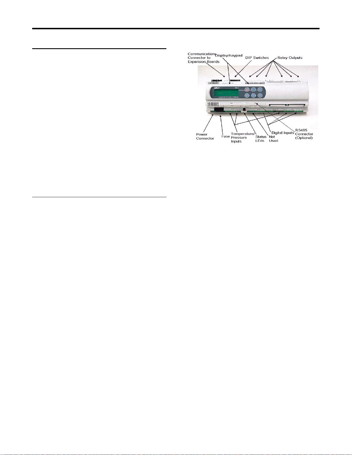
Figure 1- PCS Controller
5. PCS Hardware
The following are components of the PCS system.
1) PCS Controller
2) PCS Expansion Board
3) PCS Pressure Transducer
4) PCS Temperature Probes
This document describes the elements of the PCS
components. The schematics included with each
Protocol Refrigeration System detail the connections that
are made to the components. Refer to the schematics for
connection details.
WARNING: The Controller and Expansion board use
low voltage (24 VAC) power. However, both units have
high voltage loads connected to them. Extreme caution
should be used when servicing these units. Failure to
observe caution could lead to injury or death.
5.1.1 Input Power
The Controller uses 24 VAC (+/-15%, 50/60
Hz) (Class II) power at 50 VA.
5.1 PCS Controller
The PCS Controller is a microprocessor based system
that contains a built in display, keypad and I/O (relays
termperature inputs, pressure inputs and digital inputs).
It serves as the user interface and runs the algorithms that
control the protocol refrigeration system. Additional I/O
(relays, digital inputs and temperature inputs) can be
added using the PCS Expansion Board. The controller
contains all the I/O for all compressors in the Protocol
refrigeration system.
The temperature inputs must use the PCS temperature
sensors (described below) and the pressure inputs must
use the PCS pressure probes (described below).
Figure 1 shows a picture of the PCS Controller and
identifies the different parts of the Controller.
5.1.2 Display Contrast Adjust
The contrast of the display can be adjusted by
pressing and holding the ENTER and ESC keys
together and pressing the UP ARROW key to
increase the contrast or the DOWN ARROW
key to decrease the contrast. Refer to
paragraph 7.1.1 for an explanation of how to
identify the keys.
5.1.3 Status LEDs
There are two LED’s on the Controller that
indicate power status. If the Yellow LED is ON
this indicates that the unit is getting power. If it
is OFF, there is either no power to the unit or
the fuse is blown. The Red LED indicates the
status of the Pressure probe power output
(Connector J2 , terminals GND and +VDC). If
the Red LED is ON, there is a fault in the probe
supply. Most likely, the pressure probe is bad
or there is a short in the cable.
5.1.4 DIP Switches
Page 8
The DIP Switches on the controller should
always be in the down (OFF) position.
Page 9
Protocol Control System Users Manual 2/12/01
5.1.5 Mounting
The Controller is mounted via Din rail mount.
The Controller can be removed from the
mounting by carefully pulling on the 3 small
tabs on the bottom of the controller and rotating
the Controller up. All connectors should be
removed from the unit before removing the
Controller from the mounting.
5.1.6 Fuse
The Controller has an internal fuse. If the
Controller will not power up and you have
verified that the controller is getting input
power, you should replace the fuse. Always
replace with the same type of fuse.
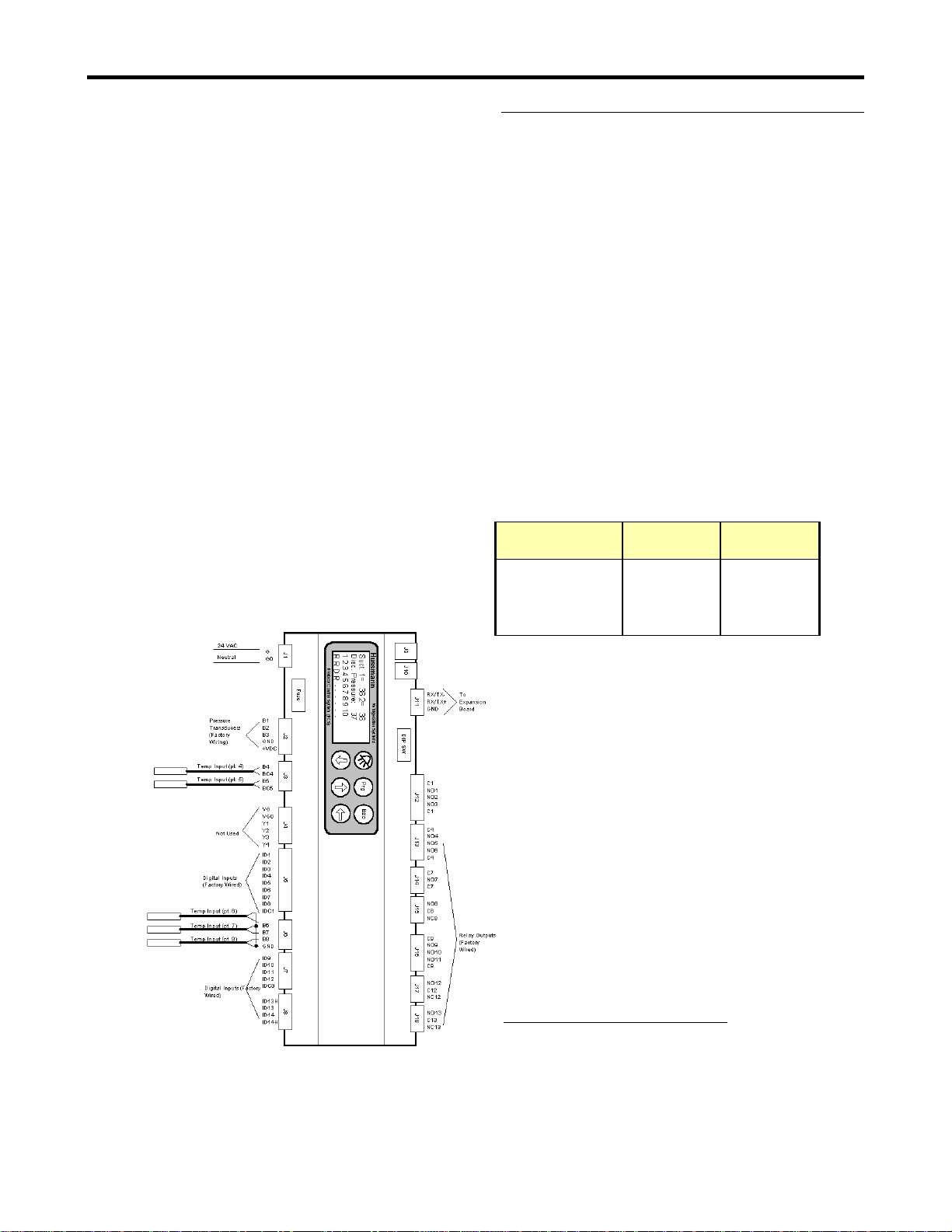
5.1.7 Controller Wiring
The field wiring for the expansion board is
shown in Figure 2. Field wiring for the
controller consists of temperature probes on
inputs 4 through 8.
Figure 2- Controller Wiring
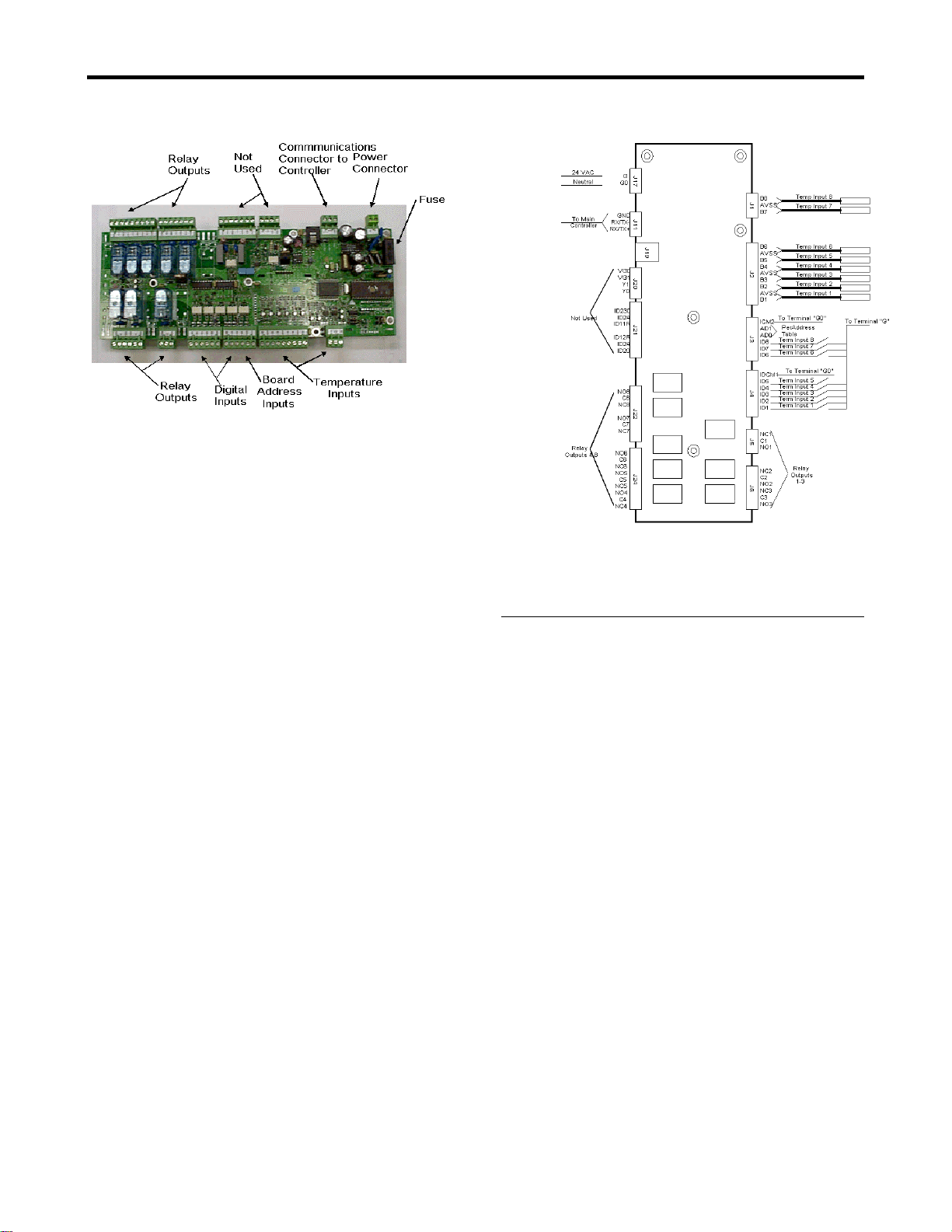
5.2 PCS Expansion Board
The PCS Expansion board is used to provide additional
I/O (relays, digital termination inputs and temperature
inputs) to the PCS Controller. Typically, the expansion
board will contain the I/O for circuits (refrigeration valve
relays, temperature inputs and defrost termination
inputs). The Expansion board contains 8 relay outputs
(Normally Open/Normally Closed outputs), 8
Temperature inputs and 8 Digital inputs.
The temperature inputs must use the PCS temperature
sensors (described below).
The Expansion board is connected to the PCS Controller
by a communications cable (Beldon 8641 or equivalent).
The PCS system supports up to 4 expansion boards. The
address of the expansion board is determined by the
wiring of inputs AD0 and AD1. Table 1 lists the
expansion board address.
Table 1- Expansion Board Addressing
Expansion
Board
Board 2
1
Board 3 OPEN
Board 4 24 VAC OPEN
Board 5 24 VAC 24 VAC
Figure 3 shows a picture of the PCS Expansion board
and identifies the different parts of the board.
AD1 AD0
OPEN OPEN
24 VAC
2
1
The first expansion board is referred to as board 2. The main
controller is referred to as board 1.
2
InTable 1, 24 VAC means tied to “G” terminal.
Page 9
Page 10
Protocol Control System Users Manual 2/12/01
Figure 3 - PCS Expansion Board
5.2.1 Input Power
The Controller uses 24 VAC (+10%/-15%,
50/60 Hz) (Class II) power at 15 VA. Note that
if using the same transformer to power the
controller and expansion board, care must be
taken to connect the G terminals on both boards
to the same side of the transformer and the G0
terminals on both boards to the same side of the
transformer.
5.2.2 Mounting
The Expansion board is mounted via standoffs.
5.2.3 Fuse
The Expansion board has an internal fuse. If the
Expansion board will not power up and you
have verified that the controller is getting input
power, you should replace the fuse. Always
replace with the same type of fuse.
Figure 4- Expansion Board Wiring
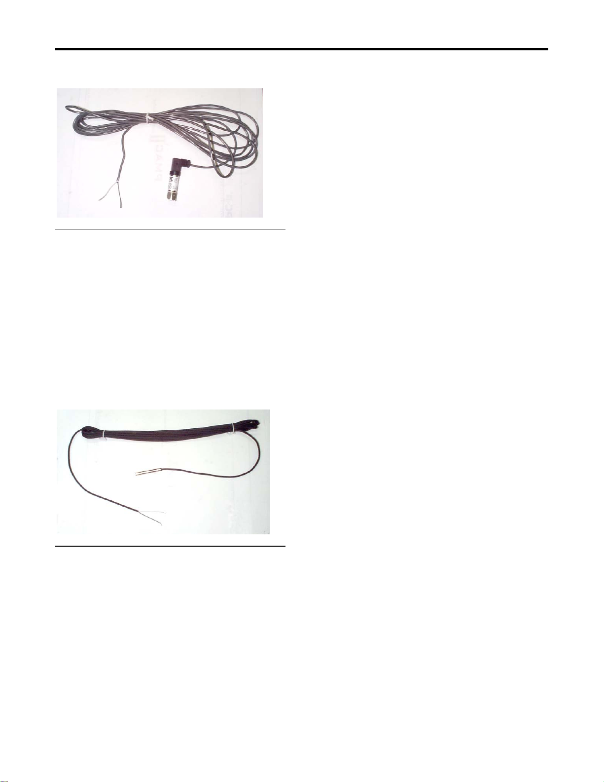
5.3 Pressure Transducer
The PCS system uses a 4/20 milliamp pressure
transducer. Inputs are provided for reading suction
pressure (optionally a second suction group pressure) and
discharge pressure. The same type of pressure
transducer is used for reading suction and discharge
pressure. The transducer is a 2 wire connection and is
polarity sensitive (refer to the Protocol schematics for
details). The system reads 0 to 362 PSI.
The wiring for the pressure transducer should not be
routed near cables carrying high voltage.
Figure 5 shows a picture of the pressure transducer.
5.2.4 Expansion Board Wiring
The field wiring for the expansion board
consists of the temperature probes and defrost
termination sensors. Refrigeration valve relays
are factory wired to terminal blocks. Figure 4
shows the connection points for the field wiring.
Page 10
Page 11
Protocol Control System Users Manual 2/12/01
Figure 5- PCS Pressure Probe
5.4 Temperature Sensor
The PCS system uses an NTC type temperature sensor to
read the temperature. The temperature sensor is not
polarity sensitive. Note that the wiring for the
temperature sensor should be routed in such a way that it
is not in close proximity to any power line cables. This
will prevent invalid readings from occurring.
The temperature sensor should be placed in the discharge
air stream to give a true indication of case temperature.
Figure 6 shows a picture of the temperature sensor.
allowing complete control of the units from the PC. For
this system each of the Controller must have a
communications card installed. The controllers must be
connected in a daisy chain fashion using Belden 8641,
24AWG, 2 conductor twisted shielded pair. This
wiring should be carefully routed away from power lines
or other high electrical noise environments
Field valve wiring should use 16/18 AWG cable
appropriate for the valve current requirements. This
wiring should not be run in close proximity to the
temperature, termination or communication wiring.
Figure 6- PCS Temperature Probe
5.5 Field wiring
All wire connections to the PCS system should be in
accordance with all applicable local and national codes.
Temperature sensors and defrost termination sensors
should be wired to the controller and expansion board
using Belden 8761, 22AWG, 2 conductor twisted
shielded pair or equivalent. This wiring should be
carefully routed away from power lines or other high
electrical noise environments.
The PCS system offers the option of using a supervisory
system where all units in the store are connected to a PC
Page 11
Page 12

Protocol Control System Users Manual 2/12/01
controller uses a PI algorithm to maintain
6. PCS Features
The PCS system has a number of features as defined in
the following paragraphs.
6.1 Overview
The PCS system has the following features:
smooth discharge pressure.
If the Protocol system uses a fluid cooler instead
of an air cooled condenser, a separate controller
will be used to control the Pump Station (refer
to the section on Pump Station Control).
The PCS controller will provide alarming on
the discharge pressure input, but will not
provide direct control in this case.
6.1.1 Circuit Control
The PCS system can control up to 10 circuits.
Control consists of controlling the defrost
schedule, controlling the circuit temperature (by
using a solenoid valve), and alarming.
The controller can schedule up to 6 defrosts per
day. The defrost can be either off cycle, electric
or hot gas. Defrost can be terminated by either
time, circuit temperature or digital (Klixon)
input.
6.1.2 Suction Pressure Control
The PCS system can control up to 6
compressors. Up to two suction groups are
supported.
Control of the pressure is by PI type algorithm
for precise pressure control. The reading from
the pressure transducer is compared to the
setpoint and the appropriate action (turning
compressors on and off) is taken to maintain the
suction pressure near the setpoint. Note that
minimum on and off times and startup delays
for the compressors can be programmed.
6.1.3 Lighting Control
Two circuits are provided for lighting control.
The lighting circuits can be turned on and off by
a 7 day schedule with one on and one off time
per day.
6.1.4 Discharge Pressure Control
The PCS system can be used to control
condensor fans. The fans are cycled in response
to the discharge pressure setpoint and the
current discharge pressure reading. The
6.1.5 Alarms
The PCS system keeps an alarm log with 16
entries. The alarm log displays the date and
time that the alarm occurred, the type of alarm
and whether the alarm is ACTIVE or has been
ACKNOWLEDGED. When an alarm occurs,
the alarm relay will activate, the ALARM key
will turn RED and the Alarm menu will
automatically be displayed. The alarm relay
will remain activated and the ALARM key will
remain RED until the alarm is
ACKNOWLEDGED.
Alarms are provided for the following
conditions:
6.1.5.1 High/Low Circuit Temperature
An alarm is signaled if the circuit temperature is
too high or too low (as determined by the alarm
setpoints).
6.1.5.2 Defrost Termination
An alarm is signaled if a defrost is set up to
terminate by temperature or digital termination,
but terminates by the maximum time instead.
This can indicate that there may be some type of
problem with the case (ice build up) or the
termination sensor.
6.1.5.3 High/Low Suction Pressure
If the suction pressure is above or below the
limits (as defined by the alarm setpoints) this
alarm will be signaled.
6.1.5.4 High Discharge Pressure
If the discharge pressure is above the limit (as
defined by the alarm setpoint) this alarm will be
signaled. Note that the discharge pressure alarm
will automatically clear (but will remain in the
Page 12
Page 13

Protocol Control System Users Manual 2/12/01
alarm log) if the discharge pressure falls below
the alarm limits.
6.1.5.5 Sensor Failures
If a temperature or pressure probe failure
occurs, this alarm will be signaled. The alarm
will provide details as to what sensor has failed.
6.1.5.6 Compressor Proof Failures
This alarm will be signaled if a compressor
proof fails. Note that proofing is optional in
the Protocol refrigeration system. Refer to the
Protocol schematics for details.
6.1.5.7 Compressor General Alarms
This alarm will be signaled if a general alarm
occurs for a compressor. A general alarm
occurs when the digital input associated with
the compressor is active. There is one digital
input for each compressor. The digital input
will be activated when the oil level sensor trips,
there is a high pressure cutout or the discharge
temperature is to high. See the Protocol
schematic for details.
will return to normal when the controller logoff
timeout occurs.
6.1.6.3 Compressor Run Time
The run time (in hours) for each compressor is
stored. The run time can be cleared if a
compressor is replaced.
6.1.5.8 Phase Loss
This alarm will be signaled if the controller
detects a phase loss.
6.1.5.9 Controller Reset
If the controller resets due to an interruption of
power, this alarm will be signaled when power
is restored
6.1.6 Maintenance/Diagnostics
The controller provides the following
capabilities for maintenance:
6.1.6.1 Force Defrost
A circuit can be forced to perform a defrost or
to cancel a defrost in progress. Note that if a
defrost is forced, the defrost will terminate
normally as defined by the circuit setpoints.
6.1.6.2 Force Compressors
A compressor can be forced on or off. Note that
the user must be logged in to force the
compressor on or off and the compressor state
Page 13
Page 14
Protocol Control System Users Manual 2/12/01
2) On other
7. Quick Start
This section of the manual provides a quick overview of
the operation of selected features of the controller. It is
intended to provide an overview of the most used
features. Refer to the Controller operation section for
more details.
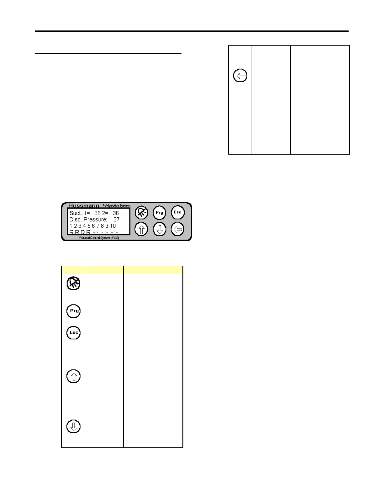
7.1.1 Display and Keypad
The controller’s user interface consist of a 4x20
LCD display with a 6 button keypad. The
display/keypad are used to see status
information on the controller and also to change
setpoints. Figure 7 shows the display and
keypad of the controller.
Figure 7- Controller Display
ENTER 1) On Main status
7.1.1.1 Cursor
Each screen can have one or more fields. The
active field will have a cursor on the first
character of the field. The cursor will alternate
between a block and the normal character for
the field.
screens- Used
to enter a value
screen- Enters
the
configuration
menus for a
given field
2) On other
screens- Used
to move
between fields
and to accept a
value.
Table 2- Controller Key Functions
Key Name Function
ALARM Enters the alarm
PROGRAM Enters maintenance
ESCAPE Return to Main
UP
ARROW
DOWN
ARROW
menu or returns to
original menu from
alarm menu
menu (depends on
current screen)
status screen (from
any screen) or move
to other status
screens (from Main
status screen)
1) On Main status
screen- Moves
between status
fields
2) On other
screens- Used
to enter a value
1) On Main status
screen- Moves
between status
fields
7.1.2 Login
Certain actions (changing setpoints, forcing
defrosts, etc.) require the user to log on to the
controller. This requires the user to enter a
password. When you must log in to perform the
action, a logon screen will pop up and you will
be prompted to enter the password. When this
happens, enter the numeric password (using the
UP or DOWN ARROW keys) then press the
ENTER key. If the password is correct the
login screen will disappear and you will be able
to perform the action. If the password is not
correct, you will not be allowed to perform the
action and the logon screen will appear again
after you press the ENTER key. Once you have
logged in, you will not have to enter the
password again unless the controller times out
and logs out. The time out will occur if you do
not press any of the keys for 5 minutes. At that
point, the controller will log you out and return
to the main status screen.
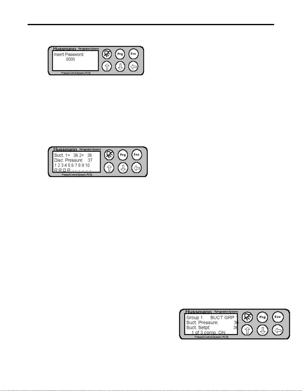
The factory default password is “0000” and it
can be changed by an authorized user.
Figure 8 shows the password screen.
Page 14
Page 15
Protocol Control System Users Manual 2/12/01
Figure 8- Password Screen
7.1.3 Main Status Screen
Figure 9 shows the main status screen. This
screen is displayed when the controller is first
powered on. This screen will also be displayed
if there are no keys pressed for a period of 5
minutes.
Figure 9- Main Status Screen
The first row on this screen shows the current
pressure reading for suction group 1 and (if
configured for two suction groups) suction
group 2. The second row shows the current
reading for the discharge pressure. The bottom
two rows show the circuit status. The numbers
1 to 10 on the third row represent circuit
numbers 1 to 10. On the last row there will be
either a “-“, “R”, “D” or “S” under each circuit
number. If a “-“ is present, this means that the
circuit has not been configured. If a “R” is
present, this means that the circuit is currently
in refrigeration mode. If a “D” if present, this
means that the circuit is in defrost. If an “S” is
present, it means that the circuit has temperature
control enabled and the circuit temperature is
currently satisfied.
To return to the main status screen from a
configuration or maintenance screen, press the
ESCAPE key once. To return to the main status
screen from another status screen, press the
ESCAPE key until the Main status screen is
displayed. Depending on which status screen
you are currently in, you might have to press the
ESCAPE key several times.
7.1.4 Configuration Screens
There are several configuration screens. In
general, these screens provide more detailed
status information and also contain setpoints.
Typically, there are several configuration
7.1.4.1 Active Fields
screens for a given function (circuit
configuration, for example). When a
configuration screen is first entered, the cursor
rests in the upper left hand corner of the screen.
If you press the UP or DOWN ARROW keys
with the cursor in the resting position, the next
or previous configuration screen will be
displayed.
Each configuration screen typically consists of a
number of fields. A field can be a setpoint or
any other area where a value can be changed.
Pressing the ENTER key with the cursor in the
resting position will advance the active field to
the first field on the screen. At this point, the
value of the field can be changed (using the
ARROW keys) or pressing the ENTER key
again will advance to the next field. If the value
of the field is changed, the ENTER key must be
pressed to accept the value and move to the next
field. Continue pressing the ENTER key until
the cursor returns to the upper left corner of the
screen.
7.1.5 Viewing/Changing Suction Pressure
Setpoint
To view or change the suction pressure setpoint,
you must enter the suction configuration screen.
To do this from the Main status screen, use the
ARROW keys to move the active field to either
Suction Group 1 or Suction Group 2. Now
press the ENTER key. The Suction Group
configuration menu will now be displayed.
Figure 10- Suction Group Configuration Screen
Page 15
Page 16
Protocol Control System Users Manual 2/12/01
The first row has the group number that you are
viewing. The name of the suction group is also
displayed on the top row. The next row has the
suction pressure reading (in PSI). The next row
has the suction setpoint (in PSI). The last row is
an indication of how many compressors (that
are assigned to this suction group) are currently
on. In this example, there are 3 compressors
assigned to the group and 1 is on.
If there are two suction groups, you can look at
the second suction group by pressing the
ENTER key to put the cursor on the group
number, then pressing the UP ARROW key to
change the value of the field to 2, then press the
ENTER key. The other active field on the
suction configuration screen is the suction
setpoint. Press the ENTER key to advance from
the suction group field to the setpoint field. The
value can now be changed by pressing the
UP/DOWN ARROW keys. After the new value
has been entered, press the ENTER key to
accept. Press the ENTER key once more to
return the cursor to the resting position. The
setpoint has now been changed.
Note that there can be up to three temperature
probes defined for a circuit and the number
displayed on this screen is the combination of
the three.
By pressing the ENTER key on this screen, you
will move the cursor to the first field which is
the circuit number. You can change the circuit
number you are currently viewing by using the
UP or DOWN ARROW keys to change the
circuit number. The temperature for the
selected circuit will automatically be displayed
(without the need to press the ENTER) key.
There may be a slight delay (up to 2 seconds)
for the display to update with the temperature
for the new circuit.
7.1.7 Viewing/Changing Circuit Temperature
Setpoint
To view or change the circuit temperature
setpoint you must enter the circuit configuration
screen. With the cursor in the resting position
(upper left hand corner), press the DOWN
ARROW key two times and a screen will be
displayed with the temperature setpoint.
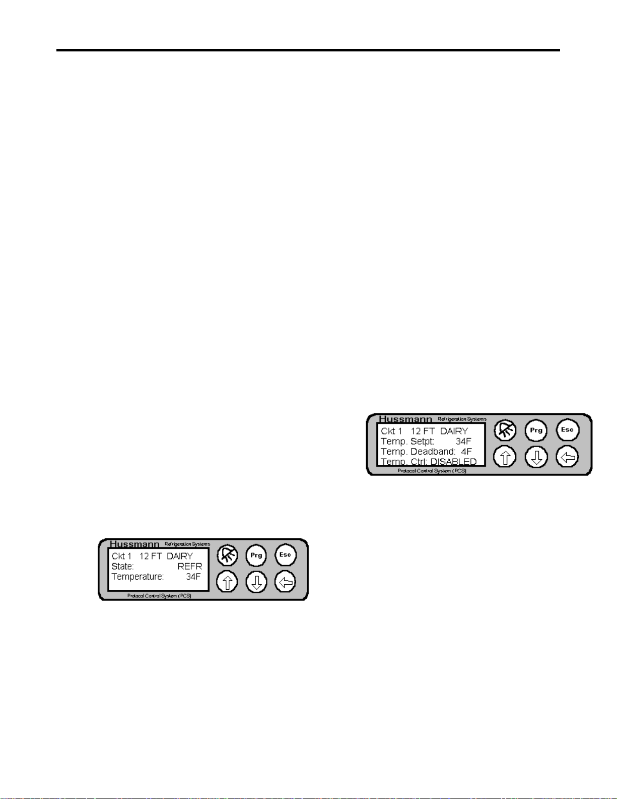
7.1.6 Viewing Circuit Temperatures
In order to view circuit temperatures, you must
enter the circuit configuration screen. To do
this from the Main status screen, press the
DOWN ARROW key until the cursor is on the
circuit number you would like to view. Then
press the ENTER key. The Circuit
configuration screen will now be displayed.
Figure 11- Circuit Configuration Screen
The first row displays the circuit number
(similar to the suction group number in the
suction group configuration screen) and the
name of the circuit. The next row displays the
current state of the circuit. “REFR” indicates
refrigeration. “DEFR” indicates defrost.
“SATISFIED” indicates that the circuit has
temperature control enabled and the circuit
temperature is currently satisfied. The third row
shows the current temperature for the circuit.
Figure 12- Temp Setpoint Configuration Screen
To change the circuit temperature, press the
ENTER key twice to make the Temp Setpt the
active field. Use the UP or DOWN ARROW
keys to change the value. Press the ENTER key
to accept the new value. Note that the active
field will automatically go to the Temp Ctrl
field. Press the ENTER key again to return the
cursor to the upper left corner (resting position).
7.1.8 Determining if a Circuit is in Defrost
To determine if a circuit is in defrost you can
look at the circuit’s status in the Main status
screen (“D”) or in the circuit configuration
screen (“DEFR”).
Page 16
Page 17
Protocol Control System Users Manual 2/12/01
7.1.9 Forcing a Defrost
To force a circuit into defrost, you must be in
any of the circuit configuration screens. From a
Circuit configuration screen, press the
PROGRAM key. The Circuit maintenance
screen will be displayed.
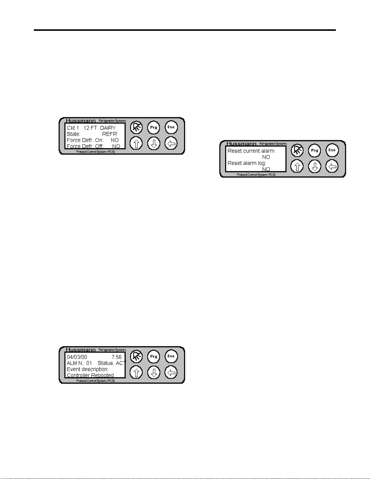
Figure 13- Circuit Maintenance Screen
The Circuit maintenance screen displays the
circuit number and name on the top row. The
current circuit state is displayed on the second
row. The third row contains a field called
“Force Defr. On:”. By moving the cursor to this
field (using the ENTER key) and pressing the
UP ARROW key the “NO” will be changed to a
“YES”. Press the ENTER key to accept the
change and a forced defrost will be started.
Note that the defrost will terminate in the
normal way (according to the circuit setpoints).
Likewise, you can cancel a defrost by moving
the cursor to the field that says “Force Defr.
Off:” and changing the “NO” to “YES” with the
ARROW key and pressing ENTER.
7.1.10 Alarms
If an alarm occurs, the controller will
automatically display the alarm log screen and
the ALARM key will turn RED. The alarm
screen can also be enter from any other screen
by pressing the ALARM key.
Figure 14- Alarm Log Screen
The Alarm screen displays the date and time
when the alarm occurred on the top row. The
next row shows the alarm number (1 to 16) and
the Status (either active (ACT) or acknowledged
(AKN). The last row gives a description of the
alarm.
To view other alarms use the UP or DOWN
ARROW keys to display other alarms that are in
the alarm log.
7.1.10.1 Acknowledging Alarms
To acknowledge an alarm you must be in the
Alarm maintenance screen. To enter the Alarm
maintenance screen, first enter the alarm screen,
then press the PROGRAM key. The Alarm
maintenance screen will be displayed.
Figure 15- Alarm Maintenance Screen
The alarm maintenance screen has two fields.
Press the ENTER key to move to the first field
that says “Reset current alarm”. Press the UP
ARROW key and the “NO” will change to
“YES”. Press the ENTER key to accept the
entry and the alarm current active alarm will be
acknowledged. The controller will
automatically return to the alarm screen.
Note that there may be more than one active
alarm. If you have cleared the alarm and the
ALARM key is still RED, use the ARROW
keys to determine if there are other alarms in the
alarm log that are active. If so, use the
ARROW keys to display the active alarm then
acknowledge the alarm as described in the
preceding paragraph.
7.1.10.2 Clearing the Alarm Log
To clear the alarm log, enter the alarm
maintenance screen as described in paragraph
7.1.10.1. Press ENTER twice to move the
cursor to the “Reset alarm log:” field. Use the
ARROW keys to change the “NO” to “YES”.
Immediately a confirmation screen will pop up
asking you to confirm that you would like to
clear the alarms. Pressing the ESCAPE key will
cancel the operation and return you to the alarm
screen. Pressing the ENTER key will result in
the alarm log being cleared.
Note: Use caution when clearing the alarm log.
Once cleared, alarm entries cannot be
retrieved.
Page 17
Page 18

Protocol Control System Users Manual 2/12/01
Figure 16- Alarm Confirmation Screen
Page 18
Page 19

Protocol Control System Users Manual 2/12/01
algorithm is used that equalizes run times
8. Controller Operation
The basic operation of the controller is described in the
following paragraphs. An overview of the menu
structure is given, the more detailed information for each
screen is presented. Where applicable, additional
information about the control algorithms, etc. are
provided.
8.1 Circuit Control
The PSC controller provides circuit control for up to 10
circuits. Each circuit can have up to 3 temperature
probes for temperature monitoring. A relay can be
assigned for temperature control. Each circuit also has a
defrost schedule that controls defrost.
8.1.1 Defrost
There are three types of defrost supported by the
controller, HOT GAS, ELECTRIC and OFF
CYCLE. Refer to the Protocol schematics for
details of the wiring for each type of defrost.
8.2.2.1 Equal Horsepower compressors
Figure 17-Equal Horsepower Example
between compressors. If there are different
horsepowers, a different algorithm is used. The
algorithms are described in the following
paragraphs.
If the compressors all have the same
horsepower, the controller uses the deadband
and setpoint to determine what compressors
should be on. “Bins” are created which
determine when a compressor is turned on and
off. One Bin is created for each compressor.
The size of the Bin is determined by the
deadband divided by the number of
compressors. An example is shown in Figure
17. In this example, the setpoint is 50 psi, the
deadband is 16 psi and there are four
compressors. As the pressure increases (going
toward the right side), more compressors are
turned on. As the pressure decreases (going
toward the left side) compressors are turned off.
8.2 Pressure Control
The PCS controller provides control of suction pressure
by cycling compressors on and off to meet the load
requirements. Up to 6 compressors are supported for a
suction group. The controller will support 1 or 2 suction
groups.
8.2.1 Switchback
Switchback is a mechanical backup mode of the
PCS. This occurs when a hard failure occurs in
the controller and it is unable to run. When this
occurs, the switchback relay (controller point 7)
will open (normally, this relay is held close).
This willcause the SBA relay to open and some
of the compressors will be powered through the
Normally Closed contacts of the SBA relay and
the Low Pressure Control. Refer to the Protocol
schematics for more detail.
8.2.2 Pressure Control Algorithm
There are two basic pressure control algorithms
used in the Controller. If all compressors have
the same horsepower, an equal horsepower
Note that there are other setpoints which affect
the minimum on and off times for the
compressors (See Figure 30 and Figure 31).
The above example shows the effect of the
Setpoint and Deadband in controlling the
suction pressure. This is basically
“Proportional” control. The controller
incorporates an additional parameter that is used
for PI (Proportional + Integral) control (See
Figure 25). This parameter is called
“Integration time” (See Figure 54). For PI
control, the controller will add (or subtract) a
Page 19
Page 20

Protocol Control System Users Manual 2/12/01
small amount to the actual pressure reading
before determining how many compressors to
turn on. The Integration time is the length of
time (in seconds) it takes for the controller to
add an error equal to the setpoint minus the
actual pressure reading.
Using the example shown is Figure 17, assume
that the actual pressure reading is 52 psi and the
integration time is 10 seconds. The error is (52
psi – 50 psi) 2 psi. In 10 seconds, 2 psi will be
added to the actual pressure and the controller
will calculate the compressors to turn on based
on a pressure of (52 psi + 2 psi) 54 psi. This is
at the bottom of Bin 3 so compressor 1,2 and 3
would be turned on at this point.
8.2.2.2 Unequal Horsepower compressors
If a controller has unequal compressors, the
algorithm is slightly different than the above
example. First the controller calculates the
number of steps it has available. For example,
if there are two compressors, the first being a 2
HP and the second being a 3 HP, there are 3
steps available (2 HP, 3 HP and 5 HP). The
controller then calculates a % capacity required
which is based on the error between the actual
reading and the setpoint. This error is divided
by the deadband and converted to a percentage
(0 to 100%). The percentage is applied to the
steps and the closest match is used. No runtime
equalization is performed for unequal
horsepower compressors.
Note that if PI control is used, an integration
error amount is added to the actual reading as
described above.
8.3 Condenser Control
The controller has the capability to control an air cooled
condenser (see Figure 32 and Figure 33). The condenser
control is very similar to the equal horsepower pressure
control with the number of compressors being the
number of fans. Note that the control of the fans is
Proportional control only.
8.4 Menu Structure
screens. Each screen type is discussed in the following
paragraphs.
Figure 18 - PCS Menu Tree
8.4.1 Status Screens
Status screens are display only screens. They
provide information about a particular function
of the controller (for example, Suction
pressure). They also serve as the entry into the
configuration screens. There are 5 status
screens. They are shown on the top row of
Figure 18. They are the Main Status, Lighting
Status, Aux Processing Status, System Status
and Release Info and Status. Each of the
screens will be described in detail later in this
document.
8.4.2 Configuration Screens
Configuration screens are screens that show
more detailed status and also have setpoints.
There are six basic types of configuration
screens: Circuit, Suction Group, Discharge,
Lighting, Aux Processing and System. These
screens are shown on row 2 in Figure 18. The
configuration screens also serve as an entry to
the maintenance screens.
Note that Figure 18 only shows one block for
each type of configuration screen. Each block
may represent many screens. For example,
there are six configuration screen for Suction
Group setup.
The screens on the controller consist of 4 basic types of
screens. They are Status screens, Configuration screens,
Maintenance screens and the Alarm screen. Figure 18
shows a menu tree that shows these different types of
8.4.3 Maintenance Screens
Maintenance screens are shown on the third row
of Figure 18. Maintenance screens allow you to
Page 20
Page 21

Protocol Control System Users Manual 2/12/01
perform a maintenance action (force a circuit
into defrost, force off a compressor, etc). Note
that there are maintenance screens for Circuits,
Suction Groups and Lighting functions.
8.4.4 Alarm Screen
The Alarm screen displays the alarm log. It can
be entered from any screen by pressing the
ALARM key.
8.4.5 Screen Navigation
8.4.5.1 Status Screens
Pressing the ESCAPE key from any
configuration or maintenance screen will always
return you to the Main Status screen. If you are
on the Main Status screen, pressing the
ESCAPE key will move you to the Lighting
Status screen. Each press of the ESCAPE key
will move to the next status screen as shown on
the top row of Figure 18.
8.4.5.3 Maintenance Screens
All maintenance screens are entered from a
corresponding configuration screen. For
example, if you wan to enter the Circuit
Maintenance (to force a defrost), you must first
enter the Circuit configuration screen. Once in
the Circuit configuration screen, press the
PROGRAM key and the Circuit maintenance
screen will be displayed. Maintenance screens
are available for Circuit, Suction Group,
Lighting and Alarms.
8.5 Screens
8.5.1 Status Screens
The status screens are shown on the top row of
Figure 18. They are described in detail in the
following paragraphs.
8.5.1.1 Main Status
Figure 19- Main Status Screen
8.4.5.2 Configuration Screens
All configuration screens are entered from a
status screen. System, Lighting and Auxillary
configurations screens are entered by pressing
the enter key when in the corresponding status
menu. Circuit, Suction Group and Discharge
configurations screens are all entered from the
Main Status screen. To enter the Suction Group
configuration screen from the Main Status
screen, move the cursor to either Suction Group
1 or Suction Group 2 pressure field, then press
the ENTER key. To enter the Discharge
configuration screen, move the cursor to the
Discharge pressure field , then press the ENTER
key. To enter the Circuit configuration screen,
move the cursor to the appropriate circuit
number (see Figure 9), then press the ENTER
key.
Once in the configuration screen, you can move
to the next configuration screen by pressing the
DOWN ARROW key (with the cursor in the
upper left hand corner). You can move back to
the previous configuration screen by pressing
the UP ARROW key. Note that at any time you
can press the ESCAPE key to return to the Main
Status screen.
Table 3- Main Status Fields
Field Explanation
Suct. 1 Suction Group 1
Pressure
Reading
Suct. 2 Suction Group 2
Pressure
Reading
Disc.
Pressure
Circuit Status Circuit 1 through
Discharge
Pressure
Reading
10 Status.
“-“- Not
configured
“R”-
Refrigeration
“D”- Defrost
“S”-
Temperature is
satisfied
Page 21
Page 22

Protocol Control System Users Manual 2/12/01
8.5.1.2 Lighting Status
Figure 20- Lighting Status Screen
Figure 21- Lighting Status Fields
Field Explanation
Lighting Ckt1 Status of lighting circuit 1
Lighting Ckt1 Status of lighting circuit 1
8.5.1.3 Aux Processing
Figure 22- Aux Processing Status Screen
Date The current date
Unit Address The address of the unit on
the supervisory
communications network.
8.5.1.5 Release Info
Field Explanation
Name The name of the controller
as set by the user
Release The version number of the
software release
Date The release date of the
software.
8.5.2 Configuration Screens
Table 4- Aux Processing Status Fields
Field Explanation
Aux State State of the auxiliary relay
Aux Temp Temperature reading of the
auxiliary input
8.5.1.4 System Status
Figure 23- System Status Screen
Table 5- System Status Fields
The configuration screens are shown on the
second row of Figure 18. Note that each
8.5.2.1 System Configuration
Figure 24- System Configuration Screen 1
configuration screen block shown in Figure 18
may have several configuration screens
associated with it. The following paragraphs
detail the configuration screens. Note that all
configuration screens for a particular function
are shown. To access the different
configuration screens, enter the first
configuration screen for the desired function,
then, with the cursor in the resting position
(upper left corner), press the DOWN ARROW
key until the desired screen is displayed.
The System Configuration screens are used to
provide “System” level setup information.
These fields should be set up first when
programming a controller.
Field Explanation
Time The current time (as kept
by the controller)
Page 22
Page 23

Protocol Control System Users Manual 2/12/01
Table 6- System Configuration Screen 1
Field Explanation
Time Used to set the time of the
controller
Date Used to set the date of the
controller
Day Used to set the Day of the
week
Unit Address Used to set the address of
the unit on the supervisory
communications network.
Figure 25- System Configuration Screen 2
Table 7- System Configuration Screen 2
Field Explanation
Unit Type Used to select between an
LP2000 and Protocol
application. Note that this
will define the maximum
number of circuits and
compressors that are
supported.
TWO GROUP Field that indicates two
suction groups (TWO
GROUP) or one suction
group (ONE GROUP), or
one suction group + a
single compressor satellite
(ONE GROUP + COMP.
SAT.).
Regulation
Type
Type of pressure control
algorithm to use either
“P”- Proportional only or
“P+I”- Proportional +
Integral. It is
recommended to use P+I
for smooth pressure
control.
Figure 26- System Configuration Screen 3
Table 8- System Configuration Screen 3
Field Explanation
Maximum
Power Load
Amps
The amount of Current
draw the Protocol unit is
rated for (used for
compressor shedding
during electric defrost)
Temperature
Display Mode
The display mode for
temperature (°F or °C)
Figure 27- System Configuration Screen 4
Table 9- System Configuration Screen 4
Field Explanation
Suct Displays the
minimum/maximum range
for the suction pressure
probe (both suction
groups). This should
always be 000/362 PSI.
Disc Displays the
minimum/maximum range
for the discharge pressure
probe (both suction
groups). This should
always be 000/362 PSI.
Figure 28- System Configuration Screen 5
Table 10- System Configuration Screen 5
Field Explanation
Comp 1 2 3 … Read only field that
displays the compressor
number.
Pt Displays the relay point
number assigned to the
compressor. Note that all
compressor relays are
located on the controller.
Grp Displays the Group
Page 23
Page 24

Protocol Control System Users Manual 2/12/01
number that the
compressor is associated
with.
Figure 29- System Configuration Screen 6
There will be one screen for each compressor
(1 – 6) that is identical to the above screen.
Table 11- System Configuration Screen 6
Field Explanation
Comp1 Amps The total amp draw of
compressor 1 (used for
compressor shedding
during electric defrost)
Comp1 HP The Horsepower of
compressor 1 (used during
capacity calculations for
the pressure control
algorithm)
Comp1 Proof Used to ENABLE or
DISABLE proofing for a
compressor. Note that the
compressor proof input
points are fixed for each
compressor (refer to the
Protocol schematics for
details)
Figure 30- System Configuration Screen 7
Figure 31- System Configuration Screen 8
Table 13- System Configuration Screen 8
Field Explanation
Compressor
Setup
IntrostageDelay
Displays the minimu m
time that will elaspe before
bringing on a different
compressor. This is useful
to prevent all compressors
from coming on all at one
time (such as after a power
fail)
Min time betw.
Same comp.
starts
Displays the minimu m
amount of time that must
elaspe (beginning with the
time the compressor is
turned on) before a
compressor can be turned
on after being turned off.
(Only with version
3.0B01)
Figure 32- System Configuration Screen 9
Table 14- System Configuration Screen 9
Table 12- System Configuration Screen 7
Field Explanation
Min On Displays the minimum on
time for the compressor
Min Off Displays the minimu m off
time for the compressor
Page 24
Field Explanation
Cond Fan 1Bd
Pt
Displays the Board
number and Point (relay)
number for the condenser
fans. Applicable only for
applications using
condenser control.
Figure 33- System Configuration Screen 10
Page 25

Protocol Control System Users Manual 2/12/01
Table 15- System Configuration Screen 10
Field Explanation
Setpoint Displays the condenser
pressure setpoint
(applicable only for
condenser control)
Deadband Displays the deadband to
use for condenser control
Figure 34- System Configuration Screen 11
This screen has no fields. It is a prompt to
change the password. If you’d like to change
the password, press the ENTER key. Note that
the default password for the controller is
“0000”.
Figure 35 - System Configuration Screen 12
This screen is displayed if you press the
ENTER key on the previous screen. Changing
the value displayed will result in the password
being changed.
Figure 36- System Configuration Screen 13
8.5.2.2 Circuit Configuration
The following are the circuit configuration
screens. Note that the top row of each screen
contains the circuit number and the name of the
circuit. The circuit number in the top row is an
active field in all screens. To view the
configuration information for a different circuit,
change the circuit number to the desired circuit
and the information for the new circuit will be
displayed.
Figure 37- Circuit Configuration Screen 1
Table 16- Circuit Configuration Screen 1
Field Explanation
State Read Only field that
displays the state of the
refrigeration circuit
(REFR- Refrigeration,
STAND BY- Temperature
is satisfied, DEFR-
Circuit)
Temperature Displays the calculated
temperature for the circuit.
Note that this may be a
combination of multiple
temperature probes
assigned to the circuit.
Figure 38- Circuit Configuration Screen 2
This screen is used to completely clear all
setpoints which are in the unit. Changing the
NO field to YES and pressing ENTER will
result in an “Are You Sure?” screen being
displayed.
Note that clearing all setpoints will results in
ALL configuration information (compressors,
circuits, suction group, etc.) being lost. Use
this with caution.
Page 25
Table 17- Circuit Configuration Screen 2
Field Explanation
State Read Only field that
displays the state of the
refrigeration circuit
(REFR- Refrigeration,
STAND BY- Temperature
is satisfied, DEFR-
Circuit)
Probe 1,2,3 Displays the actual reading
Page 26

Protocol Control System Users Manual 2/12/01
of the temperature probe.
Note that “---“ will be
displayed if a input
assignment (board/point)
has not been made for the
probe.
Figure 39- Circuit Configuration Screen 3
Table 18- Circuit Configuration Screen 4
Field Explanation
Alm Low Dlt The delta (difference)
below the setpoint that is
considered an alarm. For
example, if the
temperature setpoint is 30
and the delta is 5, the low
alarm will be at 25
degrees.
Alm High Dlt The delta (difference)
above the setpoint that is
considered an alarm. For
example, if the
temperature setpoint is 30
and the delta is 5, the high
alarm will be at 35
degrees.
Alm Displays the setting
(ENABLED or
DISABLED) for the alarm
Figure 40- Circuit Configuration Screen 5
Temp Ctrl Displays the temperature
control mode of the circuit
(ENABLED- temperature
control enabled,
DISABLED- temperature
control disabled). Note
that if the circuit is a hot
gas defrost, there is not an
option for temperature
control of the circuit.
Figure 41- Circuit Configuration Screen 6
Table 20- Circuit Configuration Screen 6
Field Explanation
Temperature
Alm Delay
Displays the amount of
delay time after the
temperature goes above or
below the alarm limits
before the temperature
alarm is logged
Show Temp Displays the mode for
calculation of the circuit
tempearture. This is only
applicable if there are
multiple probes defined for
the circuit. Note that this
field can be AVG (display
the average), MIN (display
the minimum), or MAX
(displays the maximum)
Figure 42- Circuit Configuration Screen 7
Table 19- Circuit Configuration Screen 5
Field Explanation
Temp Setpt Displays the temperature
setpoint for this circuit.
Temp
Deadband
Displays the deadband to
be applied to the setpoint if
the circuit is controlling
temperature
Table 21- Circuit Configuration Screen 7
Field Explanation
Defr Time 1 Displays the time of the
first defrost
Number Defr Displays the total number
of defrosts per day
Calculate If the user fills in the Defr
Page 26
Page 27

Protocol Control System Users Manual 2/12/01
Times Time 1 field and the
Number Defr field and sets
this field to YES, the
controller will
automatically calculate all
defrost times (evenly
spaced through out the
day)
Figure 43- Circuit Configuration Screen 8
Table 22- Circuit Configuration Screen 8
Field Explanation
Defr Length Displays the amount of
time for a defrost. If there
is no termination or there
the controller does not get
the termination signal, this
is the maximum length of
time that the defrost will
last.
Alarm Delay Displays the time delay for
an alarm if the controller is
in defrost.
Defr Min Time Displays the mi nimum
time that the controller will
run a defrost for. A defrost
will run for this minimum
amount of time, even if a
termination signal occurs
before this period of time.
Figure 45- Circuit Configuration Screen 10
Table 24- Circuit Configuration Screen 10
Field Explanation
Defr Time
4,5,6
Displays the time of the
defrost (24 hour format)
Figure 46- Circuit Configuration Screen 11
Table 25- Circuit Configuration Screen 11
Field Explanation
Defr Type Displays the type of
defrost (ELECTRIC, OFF
CYCLE or HOT GAS)
Defr Term
Type
Displays the type of
termination to use (TIME,
NONE, TEMPERATURE
or DIGITAL (Klixon))
Defr Term
Temp
Displays the termination
temperature for the circuit
Figure 47- Circuit Configuration Screen 12
Figure 44- Circuit Configuration Screen 9
Table 23- Circuit Configuration Screen 9
Field Explanation
Defr Time
1,2,3
Displays the time of the
defrost (24 hour format)
Page 27
Table 26- Circuit Configuration Screen 12
Field Explanation
Temp 1,2,3 Displays input Board and
Point for the temperature
probes for this circuit.
Note that the assignment
of the board/point defines
whether a circuit is active.
Page 28

Protocol Control System Users Manual 2/12/01
Figure 48- Circuit Configuration Screen 13
Table 27- Circuit Configuration Screen 13
Field Explanation
Probe 1,2,3
offset
Displays the offset
(degrees) that will be
applied to the probe
reading.
Figure 49- Circuit Configuration Screen 14
Table 28- Circuit Configuration Screen 14
Field Explanation
Defr Relay Displays the output point
assignment for the
refrigeration relay for this
circuit. Note that if this is
an electric defrost, the
controller automatically
takes the next relay point
on the board for this circuit
as well.
Digit. Term Displays the input point
assignment (Board/Point)
for the digital termination
for the circuit.
Electric Defr Displays the Amp draw of
the circuit’s electric defrost
heaters. Used for
compressor shedding
during electric defrost.
Figure 50- Circuit Configuration Screen 15
Table 29- Circuit Configuration Screen 15
Field Explanation
Case Type Displays the case type
defined for the circuit.
This allows a circuit to be
named to better identify it.
Scroll through all the
names by selecting the
field and pressing the UP
ARROW or DOWN
ARROW keys.
Case Size Displays the case size
defined for the circuit.
Select the size by selecting
the fields and pressing the
UP or DOWN ARROW
keys.
The above screen is the last screen for circuit
configuration.
8.5.2.3 Copying Circuit Configuration
A circuit configuration can be copied from an
existing circuit to save time during the setup
process. To copy a circuit configuration, first
setup one circuit. Next go to the first
configuration screen of the circuit that you wish
to copy into. Press the UP ARROW key and
the Circuit Copy Screen (see Figure 51) will be
displayed. Go to the Copy from Circuit field
and enter the number of the circuit that you
have already set up. The controller will then
copy all setpoints from the original circuit into
the new circuit. Note that after copying it will
be necessary to make the required changes to
the circuit (defrost schedule, board/points, etc.).
Figure 51- Copy Circuit Configuration Screen
8.5.2.4 Suction Group Configuration
The following are the suction group
configuration screens. Note that the top row of
each screen contains the group number and the
name of the group. The group number in the top
row is an active field in all screens. To view the
configuration information for a different group,
change the group number to the desired group
Page 28
Page 29

Protocol Control System Users Manual 2/12/01
and the information for the new group will be
displayed.
Figure 52- Suction Configuration Screen 1
Table 30- Suction Configuration Screen 1
Field Explanation
Suct. Pressure Read Only field that shows
the current suction
pressure reading.
Suct. Setpt Displays the suctio n
pressure setpoint
X of Y comp
ON
Read Only field that shows
how many compressors for
this suction group are on
Figure 53- Suction Configuration Screen 2
This screen shows the status of all compressors.
Figure 54- Suction Configuration Screen 3
(in seconds). The larger
this number, the slower the
controller will be to
respond to and try to
correct pressure changes.
Figure 55- Suction Configuration Screen 5
Table 32- Suction Configuration Screen 5
Field Explanation
Alm Low Dlt Displays the Low pressure
alarm delta (difference) in
PSI. Note that value will
be subtracted from the
setpoint and that will be
the value that will trigger a
low suction pressure alarm
(after the delay time)
Alm High Dlt Displays the High pressure
alarm delta (difference) in
PSI. Note that value will
be added to the setpoint
and that will be the value
that will trigger a high
suction pressure alarm
(after the delay time)
Suct. Alm
Delay
Displays the delay time
before signaling a high/low
pressure alarm
Table 31- Suction Configuration Screen 4
Field Explanation
Suct. Deadband Displays the Deadband for
the P+I algorithm. Note
this deadband is used for
both P and P+I. The larger
this field, the wider the
pressure swings that will
be allowed before
switching on/off
compressors.
Integration
Time
Displays the Integration
Time for the P+I algorithm
Figure 56- Suction Configuration Screen 6
Table 33- Suction Configuration Screen 6
Field Explanation
Pressure Offset Displays the offset (PSI)
that will be applied to the
pressure probe reading.
Page 29
Page 30

Protocol Control System Users Manual 2/12/01
Figure 57- Suction Configuration Screen 7
This is the last configuration screen for the
suction group. The suction group can be named
by selecting the name field and using the UP or
DOWN ARROW keys to select a letter, then
pressing the ENTER key to move to the next
letter.
8.5.2.5 Discharge Pressure Configuration
This screen shows the configuration screen for
the discharge pressure setup. Note that the
only field on this screen is the setting of the
Alarm setpoint (in PSI).
Figure 58- Discharge Configuration Screen
Figure 60- Lighting Configuration Screen 2
Table 35- Lighting Configuration Screen 2
Field Explanation
Type Control: Displays the control mode
for the lighting circuit.
Can be either SCHEDcontrolled from a schedule
or DIG- controller from a
digital input point (ON
when the input is high)
Figure 61- Lighting Configuration Screen 2A
8.5.2.6 Lighting Configuration
The following screens show the configuration
screens for lighting control.
Figure 59- Lighting Configuration Screen 1
Table 34- Lighting Configuration Screen 1
Field Explanation
State Read Only field that
displays whether the
circuit is ON or OFF
Output 1: Displays the output point
(board/point) assignment
for the output relay.
Note that Figure 61 shows the screen in Figure
60 if the Type Control field is set to DIGITAL.
Field Explanation
Type Control Displays the control mode
for the lighting circuit.
Can be either SCHEDcontrolled from a schedule
or DIG- controller from a
digital input point (ON
when the input is high)
Dig Input: Displays the input point
(board/point) assignment
for the input.
Figure 62- Lighting Configuration Screen 3
Page 30
Page 31

Protocol Control System Users Manual 2/12/01
Figure 63- Lighting Configuration Screen 4
Figure 62 and Figure 63 show the screens used
to configure the schedule for the lighting circuit.
An ON and OFF time can be entered (24 hour
format) for each day of the week.
8.5.2.7 Auxiliary Configuration
There are two auxiliary functions that can be
configured on the PSC. The first is the ability
to take a temperature input and turn a relay
output ON or OFF if the temperature is
above/below a setpoint. The second is the
ability to monitor two temperatures. Note that
there is no control function associated with the
temperature inputs, but alarms can be set for the
temperature inputs
Figure 64- Aux Configuration Screen 1
Figure 65- Aux Configuration Screen 2
Table 37- Aux Configuration Screen 2
Field Explanation
Temp Input
Bd/Pt
Displays the input point
assignment (board/point)
for the temperature input
Cntrl Out Displays the output point
(board/point) assignment
for the output relay.
Figure 66- Aux Configuration Screen 3
Table 38- Aux Configuration Screen 3
Table 36- Aux Configuration Screen 1
Field Explanation
Temp Setpt Displays the temperature
setpoint for the auxillary
temp control function
Temp
Deadband
Displays the deadband for
the temp control function
Control Displays the type of
control, either DIRECT
(relay closes on
temperature above setpoint
+ ½ deadband) or
REVERSE (relay opens on
temperature above setpoint
+ ½ deadband)
Field Explanation
Low Temp
Alm
Displays the low temp
alarm value. If the
Monitor temp input is
below this value for the
appropriate delay time, an
alarm will be signaled.
High Temp
Alm
Displays the high temp
alarm value. If the
Monitor temp input is
above this value for the
appropriate delay time, an
alarm will be signaled.
Delay Displays the delay time to
wait before signaling an
alarm (minutes)
Bd/Pt Displays the input point
(board/point) assignment
for the temperature input.
Page 31
Page 32

Protocol Control System Users Manual 2/12/01
Figure 67- Aux Configuration Screen 4
This screen is identical to Figure 63, but is for
the second monitor input.
8.5.2.8 Release Configuration Screen
Figure 68- Release Configuration Screen
The Release configuration screen allows the
unit to be named. Select the name field then use
the UP or DOWN ARROW keys to choose the
letters, pressing the ENTER key after each letter
is chosen.
8.5.3 Alarms
Refer to paragraph 7.1.10 for details on the
alarm screen.
Figure 69- Suction Group Maintenance Screen 1
Table 39- Suction Group Maintenance Screen 1
Field Explanation
Compressor 1 Read only field that shows
the current state of the
compressor
Force Mode Displays the control mode
of the compressor.
AUTOMATIC- the
pressure control algorithm
is controlling the state,
Warning: the Force Mode will always revert
back to AUTOMATIC when the controller logs
out so do not rely on the controller holding the
compressor off for an extended period of time.
Figure 70- Suction Group Maintenance Screen 2
ON- the state of the
compressor will be forced
on, OFF- the state of the
compressor will be forced
off.
8.5.4 Maintenance
8.5.4.1 Circuit
Refer to paragraph 7.1.9 for details of the
Circuit maintenance operation.
8.5.4.2 Suction Group
The Suction Group maintenance screens allow
you to force a compressor on or off and to see
the run times of a compressor. Note that the
following screens are repeated for each
compressor.
Table 40- Suction Group Maintenance Screen 2
Field Explanation
Compressor 1 Read only field that shows
the current state of the
compressor
Run Time Displays the run time in
hours for the compressor
Clear Run
Time
8.5.4.3 Alarm
Refer to paragraphs 7.1.10.1 and 7.1.10.2 for
details of the Alarm maintenance operation.
Setting this field to YES
will clear the run time
counter
Page 32
Page 33

Protocol Control System Users Manual 2/12/01
pump #1 will be switched on. When the output is
9. Pump Station
9.1 Overview
The Protocol Refrigeration system offers an optional
water chiller. If a water chiller is used, it will be
equipped with the Hussmann Pump Station Controller.
The Pump Station controller provides control of the
water pump and the fluid cooler (providing low and high
speed fan control and water spray control).
9.2 Hardware
The Hussmann Pump Control System (PCS) uses the
same hardware platform as the Protocol Controller. The
software load is different. The label is different to make
it easy to identify the Pump Station controller from the
Protocol Controller.
energized, pump #2 will be switched on.
The pump motors are monitored by the corresponding
proof inputs. If a pump motor is on, the corresponding
proof input should be active (contact closed). If the
proof input does not close within 5 seconds of switching
the pump motor on, the controller will switch to the other
pump and signal a proof alarm. The controller will stop
the timer until the user resets the proof failure by
entering the maintenance screen and reseting the proof
alarm. At this point the timer will start over at 0 and
normal operation will continue.
The controller will monitor the water pressure to insure
proper pressure at all times. If the water pressure is
outside of the low and high pressure setpoints for a
programmable amount of time, an alarm will be
indicated and the controller will be switched to the other
pump. The interval timer will not operate until the
condition is reset by the user.
9.3 Operation
9.3.1 Pump Motor
There are two motors on a pump station. The pump
motor algorithm will cycle the between the two motors
based on a user entered time interval (the default is 84
hours). The Pump (Relay 8) output will be used to
switch the pumps. When the output is deenergized,
9.3.2 Fluid Cooler
The fluid cooler algorithm attempts to maintain the
temperature of the glycol leaving the fluid cooler. This
is done by cycling on the spray water and low/high speed
fans. The control is a simple cut in/cut out algorithm.
The controller monitors the temperature of the glycol
leaving the fluid cooler and turns on the appropriate
outputs based on the cut in and cut out values for each.
Note that there will be a cut in and cut out parameter for
each output. When the glycol temperature is above the
cut in temperature for the each output, that output will be
turned energized. When the temperature goes below the
cut out temperature, the output will be deenergized.
Note that the outputs are independent and are controlled
only by the corresponding cut in/cut out parameters.
If a proof failure occurs for an output, an alarm will be
signaled. Other than signaling an alarm, the controller
will operate normally.
A mode will be provided that allows for winter operation
or low ambient conditions to lockout the Spray water
pump. A cut in and cut out setpoint will be provided that
locks out the water pump based on the ambient
temperature. If the ambient temperature is below the cut
in, the water pump output will be locked out and will not
be energized. If the temperature comes above the cut
out, the water pump output will be energized based on
the spray water cut in/cut out setpoints. There will also
be a glycol override temperature setpoint. When the
glycol temperature is above this setpoint the spray water
Page 33
Page 34

Protocol Control System Users Manual 2/12/01
pump output will operate normally based on the gylcol
temperature and the spray water cut in/cut out setpoints.
9.4 Screens
9.4.1 Status Screens
There are four status screens as shown in the following
paragraphs. Pressing the ESC key will move between
the status screens.
Figure 71- PSC Main Status Screen
Table 41- Main Status Fields
Field Explanation
IN Glycol In Temperature
OUT Glycol Out Temperature
AMB Ambient Temperature
PSI Pressure reading
PUMP Status of the PUMP (P1 or
P2)
SPRAY Status of the Spray Pump
LFAN Status of the Low Speed
Fan Output
HFAN Status of the High Speed
Fan Output
Figure 73- PSC Pump Date/Time Screen
Table 43- Date/Time Status Fields
Field Explanation
Time Current Time
Date Current Date and Day
Unit Address The address of the unit on
the supervisory
communications network
Figure 74- PSC Release Screen
Table 44- Release Fields
Field Explanation
Name Name of this controller as
set by the user
Release Version number of the
software release
Date Release date of the
software
Figure 72- PSC Pump Status Screen
Table 42- Pump Status Fields
Field Explanation
On Line Pump Which pump is on
P1 Run Time Total run time of pump 1
P2 Run Time Total run time of pump 2
Page 34
9.4.2 Configuration Screens
There are ten configuration screens for the PSC
controller. The configuration screens are
entered by starting at the Main Status screen and
pressing the ESC key until the Password Screen
(shown in Figure 75) is displayed. Enter the
password, then press the ENTER key and the
first configuration screen (shown in Figure 76)
will be displayed. Scroll to the next
configuration screen by pressing the DOWN
ARROW with the cursor in the upper left corner
of the screen.
Page 35

Protocol Control System Users Manual 2/12/01
Figure 75- PSC Password Screen
Figure 76- PSC Configuration Screen 1
Table 45- PSC Configuration Screen 1 Fields
Field Explanation
Force SP ON Set to YES to Force the
Spray Pump On. Note that
the force will revert to the
original value in 3 minutes.
Force LF ON Set to YES to Force the
Low Speed Fan On. Note
that the force will revert to
the original value in 3
minutes.
Force HF ON Set to YES to Force the
High Speed Fan On. Note
that the force will revert to
the original value in 3
minutes. Note that if the
High Speed is forced to
ON, the Low Speed Fan
will be turned OFF.
Switch Pump Set to YES to change the
pump. If the pump is
switched, it will remain on
until the pump timer
expires. Note that the
pump timer is reset when
the pumps are changed.
Table 46- PSC Configuration Screen 2 fields
Field Explanation
On Temp Temperature to turn the
Spray pump ON
3
Off Temp Temperature to turn the
Spray pump OFF
Figure 78- PSC Configuration Screen 3
Table 47- PSC Configuration Screen 3 fields
Field Explanation
On Temp Temperature to turn the
Low Speed Fan On
4
Off Temp Temperature to turn the
Low Speed Fan OFF
Figure 79- PSC Configuration Screen 4
Table 48- PSC Configuration Screen 4 Fields
Field Explanation
On Temp Temperature to turn the
High Speed Fan On
Off Temp Temperature to turn the
High Speed Fan OFF
Figure 80- PSC Configuration Screen 5
Figure 77- PSC Configuration Screen 2
Page 35
3
Note that operation of the Spray Pump will be affected by the
Winter Summer Mode as defined in Table 49.
4
Note that the Low Speed Fan will be turned off if the High
Speed Fan comes on.
Page 36

Protocol Control System Users Manual 2/12/01
Table 49- PSC Configuration Screen 5 Fields
Field Explanation
Winter On If the ambient temperature
is below this setpoint, the
spray pump will not be
turned on
Winter Off If the ambient temperature
is above this setpoint, the
spray pump can be turned
on
Override On If the outlet temperature is
above this setpoint, the
spray pump will be
enabled regardless of the
ambient temperature. Note
that if the outlet
temperature goes above
this setpoint, a High Temp
Alarm will be activated.
Override Off If the outlet temperature is
below this setpoint, the
spray pump will be
disabled if the ambient
temperature is below the
Winter On setpoint
Figure 81- PSC Configuration Screen 6
Figure 82- PSC Configuration Screen 7
Table 51- PSC Configuration Screen 7 Fields
Field Explanation
Max Range Maximum range of the
pressure probe. Should
always be 362 PSI.
Min Range Minimum range of the
pressure probe. Should
always be 0 PSI.
Offset Offset of the pressure
probe
Figure 83- PSC Configuration Screen 8
Table 52- PSC Configuration Screen 8 Fields
Table 50- PSC Configuration Screen 6 Fields
Field Explanation
Minimum PSI Low Pressure setpoint for
the water pressure. If the
pressure is below this
value for the delay time, an
alarm will be activated.
Maximum PSI High Pressure setpoint for
the water pressure. If the
pressure is above this
value for the delay time, an
alarm will be activated.
Alarm Delay Delay time before
activating pressure alarm
Field Explanation
Pump 1 Initial value for run time
value for Pump 1 (hours)
Pump 2 Initial value for run time
value for Pump 2 (hours)
Pump Interval Time interval to switch
between pumps (hours)
Figure 84- PSC Configuration Screen 9
Table 53- PSC Configuration Screen 9 Fields
Field Explanation
Time Used to set the time of the
controller
Date Used to set the date of the
controller
Day Used to set the day of the
controller
Page 36
Page 37

Protocol Control System Users Manual 2/12/01
Unit Address Used to set the address of
the unit on the supervisory
communications network
Figure 85- PSC Configuration Screen 10
Table 54- PSC Configuration Screen 10 Fields
Field Explanation
Name Used to set the name of the
controller
Password Used to set the password
of the controller
Temperature Used to set the temperature
display mode of the
controller
Figure 86- PSC Configuration Screen 11
9.5.2 Spray Pump Fail
The proof for the Spray Pump failed.
9.5.3 Low Speed Fan
The proof for the Low Speed Fan failed.
9.5.4 High Speed Fan
The proof for the High Speed Fan failed.
9.5.5 Pump 1
The proof for the Pump1 failed.
9.5.6 Pump 2
The proof for the Pump 2 failed.
9.5.7 High Discharge Pressure
Figure 86 shows the last configuration screen. When this
screen has been reached, the configuration for the
controller has been completed.
9.5 Alarms
The alarm management in the pump station is very
similar to the alarms in the Protocol controller. Press the
ALARM key to enter the alarm screen (shown in Figure
87 ). Press the PRG key to enter the maintenance menu.
There is a prompt to reset alarms in the maintenance
menu. Entering YES to this prompt will reset the current
alarm and clear the alarm menu.
The following Alarms are provided in the Pump Station
controller:
9.5.1 Controller Reboot
Power was applied to the controller.
The pressure was above the alarm setpoint for
greater than the alarm delay time.
9.5.8 Low Discharge Pressure
The pressure was below the alarm setpoint for
greater than the alarm delay time.
9.5.9 Pressure Sensor Fail
The pressure was above the alarm setpoint for
greater than the alarm delay time.
9.5.10 Inlet Temp probe Fail
The inlet temperature probe failed.
9.5.11 Outlet Temp probe Fail
The outlet temperature probe failed.
Page 37
Page 38

Protocol Control System Users Manual 2/12/01
9.5.12 Ambient Temp Fail
The ambient temperature probe failed.
9.5.13 Alarm Winter Override
The outlet temperature was higher than the
Winter Override setpoint.
Figure 87- PSC Alarm Screen
Page 38
Page 39

Protocol Control System Users Manual 2/12/01
b) RS485 Converter
10. Supervisory System
10.1 Overview
The PCS Supervisoy system provides a means to monitor
and supervise Protocol Controllers from a central point
within a store. The system runs a PC and communicates
with the controller via an RS485 network. The system
requires an RS485 converter and a software protection
key to be installed on the PC.
10.2 Supervisory Connection Wiring
The RS485 network wiring must be wired correctly in
order for the Supervisory system to function. Refer to
the drawing in
Appendix A for details.
10.3 Requirements
The following are the general requirements for the
computer which will run the supervisory system.
1. CPC P4 800 Mhz (or equivalent)
2. 512 MB Ram
3. 20 GB Hard Drive
4. 1024 x 768 Video
5. 2 serial ports (COM1/COM2) (for fax
dialout/Remote Access and RS232/RS485 Adpater)
6. CD-ROM Drive (Speed not critical)
7. US Robotics 56K Data/Fax Modem (Important:
Hardware modem, not software modem
8. PS2 Mouse and Keyboard
9. 15” SVGA Monitor
10. Windows 2000 SP4 or Windows XP SP1
11. Modem for Fax Dial out and remote access
12. Internet Explorer v6.0 or newer
Additional Information
1) PC must be dedicated to running the supervisory
system
2) UPS must be provided to insure no data loss (USB
type preferred for auto shutdown)
Other Accessories
1. Outside phone line or network access at PC (for fax
dial outs and remote access)
2. RS-485 cable type = Belden 8641 2 conductor
shielded
3. Supervisory Kit (shipped with Protocol’s to job site)
which consists of
a) Supervisor Software
c) Transformer
d) DB25 to DB9 RS232 cable
e) Connector for RS485 converter
f) Terminating Resistors
10.4 Software Installation
Note that the PCS Supervisory System runs on the
Windows platform. It is assumed that the user is familiar
with Windows and general windows commands. Consult
the Windows User Manual if you have questions.
The Supervisory software is called PlantVisor.
Use the following steps to install the PCS software.
1) Insure that you are logged on as a local user with
Administrator privileges.
2) Insert the CD into the CD Rom drive. If the
program does not start, run the install program by
clicking the start button, selecting run and typing
X:\setup, where X represents the drive letter for the
CD Rom.
The installation screens you will see are described in the
following paragraphs.
Figure 88- Installation Screen
On this screen select English as the language, Select
Local then press the Setup button. A dialog box will pop
up asking you to install Microsoft FAX software
(necessary to fax alarms). Select Yes to install the fax
software (note that you may need to have the original
Windows CD available for this step.
The installation program will then copy the necessary
files to the PC’s harddrive. A dialog box will then pop
up informing you that you will need to answer yes to the
next dialog box. Select OK and a new dialog box will
pop up informing you that a digital signature is not found
Page 39
Page 40

Protocol Control System Users Manual 2/12/01
y
and asking you if you want to continue the installation.
Select Yes and the installation will continue.
After the installation, a dialog box will be displayed
asking you to reboot the computer. Select Yes and the
PC will be rebooted.
10.5 Hardware Installation
There are two pieces of hardware that must be installed
on the PC for the PCS Supervisory system to operate.
The first is an adapter that converts the RS485 signals
from the PCS supervisory network into RS232 signals
that can be connected to the PC. The second is a software
Key that the must be installed. The following paragraphs
describe how to install each of these devices.
10.5.1 RS485 Adapter
The RS485 Adapter converts the RS485 signals from the
PCS Supervisory network to RS232 signals. The RS485
adapter comes with a transformer and a RS232 cable. To
install the adapter do the following:
1) Connect one end of the RS232 cable to the DB9
connector (left side of the adapter) on the Adapter
and connector the other end of the cable to the DB9
connector for COMM1 on the PC.
2) Connect the RS485 PCS Supervisory network cable
to the 3 pin RS485 connector. Depending on the
network wiring, a terminating resistor may also
need to be applied at this connector. See Appendix
A for details.
3) Connect the power supply (12 VAC) to the adapter.
Note that there is power LED that should light up
when power is applied.
The adapter has LED’s that light to represent serial
network traffic being sent and received (RX and TX
LED’s). Under normal operation these LED’s should
flash at an intermittent rate. TX represents the PC
attempting to communicate to the controller’s and RX
represents the controller’s answering. Note that if the
RX LED does not flash, this indicates a problem on the
Supervisory network (wiring, controller addressing).
Figure 89- RS485 Adapter
Power Supply
Connector
DB9 connector
(to PC RS232
serial Port)
Power Supply
RS232
Computer
12 VAC
PWR
RX
TX
RX-/TXRX+/TX+
GND
RS485
Network
RS 485 3
pin
connector
(to
Supervisor
network)
10.5.2 PlantVisor Software Key
The PCS Supervisory system requires that a software
Key (referred to as a SmartKey in the documentation) be
installed on the USB port for the software to operate.
See Figure 90 for a picture of the Key. If the Key is not
installed , the PlantVisor Engine will run in Demo mode
as indicated by the letters DEMO MODE at the top of
the PlantVisor Engine screen (See Figure 91 ).
Figure 90- PlantVisor Software Key
Note that if the SmartKey is not present or recognized
by PlantVisor the program will run in Demo Mode and
will terminate in approximately 3 hours- all logging,
alarming and other functions associated with
PlantVisor will stop when PlantVisor terminates.
Page 40
Page 41

Protocol Control System Users Manual 2/12/01
Figure 91- PlantVisor Engine Demo Mode
10.6 Remote Access
If Remote communications is desired from an off site PC
only one modem is required. Plantvisor will use the
same modem for inbound and outbound calls. There is
no need for PCAnywhere with PlantVisor. A typical
configuration for the PC is as follows:
a) COM1- for an external modem for fax/remote
access (can be eliminated if PC has an internal
modem)
b) COM2- RS232/RS485 converter
c) USB- For the PVKey
supervisory functions) after a short period of
time.
Figure 92- Plantvisor Engine Screen
Figure 93- Logon Screen
10.7 Operation
10.7.1 Running the PCS Supervisor
To run the supervisory software, click the start
button and select PlantVisor. The software will
then launch the PlantVisor engine as shown in
the PlantVisor software will run in Demo mode
(as described in paragraph 10.5.2 and will
terminate (stopping all logging, alarming and
other supervisory functions) after a short period
of time.
Figure 92. After the Engine starts and all
modules are running, a Internet Explorer
browser page will automatically be opened
displaying the PlantVisor logon screen (Figure
93). Note that if a KEY is not present, the
PlantVisor software will run in Demo mode (as
described in paragraph 10.5.2 and will terminate
(stopping all logging, alarming and other
Enter your login (default is Administrator or
Guest with no password) and click OK.
Note: it is recommended that after logging in
for the first time the passwords should be
changed to prevent unauthorized access.
The main screen will be displayed as shown in
Figure 94.
Page 41
Page 42

Protocol Control System Users Manual 2/12/01
Figure 94- Main Screen
10.7.2 Navigation
The PlantVisor system is web based and uses
the Internet Explorer to display the web pages.
Normal Internet Explorer commands (such as
the Back Arrow) can be used to navigate
through the web pages. There is also a left
menu tab or pane that is used to navigate.
Figure 95
items.
Figure 95- Navigation Examples
shows the location of these menu
Alarm/Events- Use the Alarms item to display
info about alarms. Note that a submenu is used
to see All Alarms, Only Active Alarms or
Events that have occurred.
Report- The Report menu item is used to create
various reports that detail operation of the
system.
Service- The Service menu item is used to
configure the system.
Logout- The Logout menu item is used to
logout of the PlantVisor system.
Help- The Help menu item brings up a Help
information for the system.
10.7.3 Configuration
When the supervisor is first started, you will
need to configure certain parameters to insure
correct operation. The follow paragraphs
describe these steps. Note that there are several
screens with configuration information that
must be completed. In general, after the
appropriate information has been entered on a
screen, the Save & Exit button must be pressed
to save the configuration information entered.
If Save & Exit is not pressed, the configuration
information will be lost.
10.7.3.1 Network
Select the Service menu item from the left side
of the Main Screen. The menu will expand and
show 4 additional choices (Network, Scheduler,
Backup, Users). Select the Network item from
the submenu. The screen will change to the
network setup menu.
In general you will use the left hand menu pane
to navigate through various levels of the system.
Note that depending on the menu item a
submenu could be displayed.
Devices- Select the Devices Menu Item to
display the devices connected to the PlantVisor.
In the example above the devices are shown in
the right hand pane as RACKA and RACKB
Figure 96- Network Management Screen
Page 42
Page 43

Protocol Control System Users Manual 2/12/01
Select the Site configuration item from the
Network Management Screen and the Site
Configuration Screen will be displayed.
Figure 97- Site Configuration Screen
Note that the Site Configuration Screen is
organized with Buttons along the top for
General, Line 1, Line 2, etc. Press the General
button to display the Site name and other
general information. In the Site Configuration
Screen, enter a name for the site and a Site ID
number. Note that the Site ID number must be
a unique number such as a modem telephone
number, etc. The Site Telephone # and
Password are optional.
Press the button labeled Line 1 to display the
serial line configuration screen. In this screen
you will enter information about what units are
connected to the RS485 converter.
Figure 98- Serial Line Configuration Screen
You must have a separate address for each PCS
controller that is connected to the RS485
Adapter. Refer to the PCS controller manual
for information on how to set the serial address
of the controller. For the Serial Configuration,
use the defaults for the Comm Port (unless the
RS485 Adapter is connected to a different
Comm Port), Baud Rate and Type (COM1,
19200, RS485). Below the “Serial
Configuration” section, is a section labeled
“Configuration Of Devices.” In this section you
must enter an address and type for each PCS
Controller connected to the RS485 Adapter.
In order to add and configure the units, You
must first select the address, then set the device
type in the drop down box, then rename the
units to a descriptive name. There are two ways
to set the address for each unit, individually or
as a group. To set the address individually, set
the “From” and “To” boxes to the serial address
of the unit, a new unit with the given address
will be added to the list of devices. To set the
address for a range of units, select the first
address in the “From” box and the last address
in the “To” box. After the address has been set,
set the device type to either Hussmann Protocol
Controller or Hussmann Pump Station
Controller (click on the check mark beside the
box and scroll the list of items until the correct
one is shown). New units with the appropriate
address or range of addresses will be added to
the list of devices. Once the units are added,
name the units with a descriptive name. Note
that the default name is unitX where X
represents the address. The name can be
changed by selecting the name in the Device
Description column and entering the new name.
When finished with the serial and site
configuration, press the Save & Exit button.
Note that the address selected for each unit
must match the address set in the appropriate
PCS controller in order for the PlantVisor
system to communicate with the PCS
controllers. Refer to paragraph 10.9.3 for
details on how to tell if controller is
communicating with the PlantVisor.
Return to the Site Configuration Screen Figure
97 and click the Modem Setup button to enter
the modem setup screen.
Figure 99- Modem Setup Screen
Page 43
Page 44

Protocol Control System Users Manual 2/12/01
the Fax machine after setting up the fax portion
of Plantvisor.
10.7.3.2 User Setup
The next step in the configuration is to set up the users.
Click the Users button on the left hand menu tab to enter
the User setup screen.
Figure 100- User Configuration Screen
In the modem setup screen enter the modem
from the drop down list under the TAPI field.
You will then see a message explaining that the
machine will be rebooted when Save is selected.
Click the OK button in the message box. The
Remote Site Telephone # is used if this PC will
be dialing into a PlantVisor remote (off site-
Not at the store) PC. The “Digit to exit phone
exchange” allows a character to be dialed in
certain circumstances where It is necessary to
dial some digit before getting an outside line.
The GSM Server and Code fields are not used.
If no remote PC will be utilized, leave the
telephone number blank. When the modem
setup is completed, press the Save & Exit
button. The PC will now reboot to configure
the modem. When the setup has been
completed, it may take several minutes for the
Plantvisor engine to shut down and reboot. Do
not force the reboot, let the PC complete the
process.
After the PC has rebooted, start the Plantvisor
application again and click the Scheduler link
under the Service Dropdown menu. You should
now be able to click the checkbox on the Fax To
selection. Type in the fax number exactly how
it needs to be dialed (i.e. with the appropriate
digit to access an outside line followed by a
comma, then the fax number (For example, if
the fax number is 123-456-7890 and you must
dial an 8 for an outside line, the Fax number
would be entered as 8, 1234567890). If you
insert an incorrect number, you must correct the
number then shut down and restart PlantVisor
There are 2 users configured by default, Administrator
and Guest. Additional users can be added by clicking the
Add New User button. Click the Edit Icon for each user
to customize the rights and password of each user. Note
that the User Configuration screen has both Service &
Manufacturing parameters. For the PCS PlantVisor
system, these are the same and should both be checked if
a user is allowed to change parameters of the PCS
controllers.
To add a new user, click the “Add New User” button.
The screen shown in Figure 101 will be displayed. Enter
the Username and password for the new user, then
configure the user rights by checking the appropriate
button to Allow or Deny each of the privileges listed.
Note that FTP access should be left unchecked for the
user. When finished with the configuration, press the
Save & Exit button to return to the User Configuration
screen.
for the change to take effect. Note that
PlantVisor does not follow the Windows dialing
property rules in the Windows modem setup
area.
Important: Always verify that the Fax works
properly and that a Fax is correctly received by
Page 44
Page 45

Protocol Control System Users Manual 2/12/01
Figure 101- Add New User Screen
10.7.3.3 Scheduler & Alarm Priorities
The scheduler allows the user to configure the
way various events are handled by the
supervisory system. Click the Scheduler button
on the left hand menu tab to enter the Scheduler
configuration screen shown in Figure 102.
Figure 102- Scheduler Configuration Screen
schedule. To configure the Scheduler to dial an
alarm, check to box labeled “Fax To”, then fill
in the telephone number (including any digits
needed to get an outside line) of the fax
machine that will be dialed if an alarm occurs.
The “Send SMS” box should not be checked.
Near the bottom of the page is a schedule
showing the days of the week and the hours in
the day. A check mark in the box signifies that
the schedule is active at that particular time.
This feature can be used to have different alarm
handling during the evening or on weekends. A
nd
2
Alarm schedule would be setup with the new
configuration information and the active times
selected for the 2
appropriate Fax information must be set for
nd
schedule. Note that the
each alarm schedule.
Note that you must press the Save button after
each schedule is configured.
After the schedules have been setup, the alarm
priorities can be set up. Click the “Alarm
Priority” button in the Scheduler Configuration
screen to access the Alarm Priority screen
(shown is Figure 103). There are 2 priorities,
LOW and HIGH and each can have it’s own
alarm delay time. Set the appropriate delay
times by entering the minutes to delay before
alarming and taking the action as defined in the
Scheduler Configuration screen.
In the scheduler configuration screen, there are
3 alarm handling schedules that can be setup as
well as alarm priority and configuration.
There are 3 alarm schedules. Each schedule an
action is defined (i.e. Fax the alarm, dial out to a
remote PlantVisor, Send email, Print etc.). Note
that Send SMS message is not supported. Set
the appropriate information for the alarm
Figure 103- Alarm Priorities Screen
After the delays have been set, you will need to
configure the individual alarms from the PCS
controller as High or Low priority. To do this
access the Hussmann Protocol Controller device
type which will be shown below the delay
Page 45
Page 46

Protocol Control System Users Manual 2/12/01
times. Scroll down the list until the appropriate
device is selected. Only the Hussman Protocol
Controller and Hussman Cooling Tower are
supported. To configure the priorities of these
devices, select the appropriate device, then press
the Edit Icon for the device.
All alarms in the device will be displayed, along
with a checkbox for LOW or HIGH priority
(See Figure 104). For each alarm select the
desired priority by checking the appropriate
box, then press the Save & Exit button at the
bottom of the screen.
Figure 104- Device Alarm Settings
Important: Always verify that the Fax works
properly and that a Fax is correctly received by
the Fax machine after setting up the Alarm &
Scheduler portion of Plantvisor.
Note that a report can be generated by Clicking
on the “Report” button. Numerous information
can be included in the report including:
1) Last time the supervisory started
2) Any faxes
3) Any units off line
A time period can be specified for a report
allow you to drill down into a specific date/time
range.
The configuration of the PlantVisor software is
now complete.
10.8 Running the System
10.8.1 Troubleshooting
See the troubleshooting guide in Appendix BTroubleshooting if there is a problem with the
supervisory software.
10.9 PCS Supervisory System Screens
The following section describes the screens of the PCS
supervisory system. The information on these screens
are generally the same as previously described under the
appropriate section of the PCS manual. For detailed
information about a status value or setpoint, refer to the
appropriate section of the PCS manual.
10.9.1 General Information
There are two basic types of information on the
Supervisory screens. Status information that is
for display only (for example, a circuit
temperature) and setpoints that can be changed
(for example, the circuit temperature setpoint).
Numeric setpoints are changed by selecting the
setpoint field by clicking on the field and
changing the value using the numeric keys on
the keyboard or the up/down arrows on the
numeric dialog box.
Note that in any screen where changes can be
made, a Submit Changes button is present. Any
changes made in the screen (i.e. setpoints) will
not be sent to the Protocol Controller until the
Submit Changes button is clicked. Failure to
click the Submit Changes button will result in
the loss of any changes made in the screen.
10.9.2 PlantVisor Engine Screens
When the PlantVisor system software is started,
the PlantVisor engine will startup first, followed
by the Supervisory System. The PlantVisor
Engine screen, shown in Figure 105 shows the
status of the PlantVisor system as it starts up.
Once the startup is complete, A browser
window will be automatically launched with the
Supervisory System Main Screen displayed. In
order to close the Plantvisor System, click the
Manage PlantVisor button in the Engine Screen.
A Detailed Status screen will be displayed as
Page 46
Page 47

Protocol Control System Users Manual 2/12/01
shown in Figure 106. Clicking the Close
PlantVisor button in this screen will display
prompt a request for a password. You must
enter the correct username and password (that
has been configured with appropriate rights to
close PlantVisor- see paragraph 10.7.3.2 ) to
close PlantVisor (Shown In Figure 107).
Figure 105- PlantVisor Engine Screen
Figure 106- PlantVisor Engine Detail Screen
10.9.3 Supervisory Main Screen
When the PlantVisor browser is started the main
screen will be displayed (See Figure 108). The
main screen displays the PCS units that are
connected to the PC via the RS485 converter
(shown as RackA for this example) and will
display active alarms (that have not been
acknowledged) for the units. If the PCS
Controller is communicating with the
PlantVisor appropriately there will be either a
green dot or red dot next to the Name. The
green dot indicates normal communications and
the PCS Controller is not in alarm. The red dot
indicates normal communications and the unit is
in alarm. A grey dot indicates no
communication with the PCS Controller. In
order to navigate to a particular unit, click on
the unit name. The main screen for that unit
will then be displayed.
In order for PlantVisor to perform logging,
alarming and other supervisory functions the
PCS controllers must be communicating with
the PlantVisor PC.
Figure 107- PlantVisor Engine Close Screen
Figure 108- Supervisory Main Screen
10.9.4 Unit Main Screen
Page 47
The Unit Main Supervisory Screen is shown in
Figure 109. This screen contains general status
of the functions associated with the protocol
Page 48

Protocol Control System Users Manual 2/12/01
unit and a means to display screens which allow
the user to change parameters or display
graph’s, etc. The following paragraphs describe
the specific items on the Main Screen.
Figure 109- Unit Main Screen- No Alarms
10.9.4.1 Misc Information
On Line is GREEN if the unit is communicating
with the PC (See Figure 111). If the unit has an
active alarm, an RED Alarm indication will be
displayed below the Online indicator (See
Figure 110). Note that clicking on the Alarm
button will send an Alarm acknowledgement to
the PCS Controller acknowledging the alarm.
See paragraph 10.9.11 for more information on
alarms.
Figure 110- Main Screen With Alarms
10.9.4.3 Suction/Discharge
This section of the screen shows the status and
setpoints for the suction groups and the
discharge pressure. Pressure is shown in the
first column. Other columns show the setpoints
and alarm information. Clicking on the button
labeled “Compressor Setup” will display the
Suction/Compressor Setup Screen, where the
setpoints can be changed.
10.9.4.4 Circuits
The circuit state (refrigeration or defrost), the
current temperature and the setpoint are shown
for all circuits. The user can view a graph of the
circuit temperature by clicking on the
appropriate button located beneath the circuit.
10.9.4.5 Compressor Information
10.9.4.6 Navigation to other screens
Clicking on the appropriate “Setup” bu tton will
enter the Circuit Setup Screen where additional
information is displayed and setpoints can be
changed.
The status of all compressor’s for the Protocol
unit are shown in the lower left portion of the
screen. For each compressor (1 through 6) the
state of the compressor is shown (ON or OFF)
as well as the suction group that it is assigned to
and the relay point (of the main controller) that
it is associated with.
There are six buttons located at the bottom of
the main screen. These buttons are used to
navigate to other screens for status information
or to change setpoints. Each of these screens
are described in the following paragraphs. Note
that in each screen, a “Back” button is provided.
Clicking on the “Back” button will return to the
Main Screen.
10.9.4.2 Date/Time
The Date and Time of the protocol unit are
shown in the upper right hand corner. Click on
either to display a dialog box that will allow the
Date and Time to be changed.
Page 48
10.9.5 System Setup
Pressing the “System Setup” button located on
the Main Screen will display the System Setup
screen. The System Setup screen is shown in
Figure 111.
Page 49

Protocol Control System Users Manual 2/12/01
Figure 111- System Setup Screen
This screen is used to set basic system
information about the Protocol units and
Condenser control information.
10.9.6 Suction Group/Compressor Setup
The Suction Group/Compressor Setup screen is
used to enter the setpoints associated with the
Suction Groups, the Discharge Pressure Alarm
and the Compressor information. The Suction
Group/Compressor Setup screen in shown in
Figure 112. A graph of the pressures can be
viewed by pressing the “Graph” button in this
screen.
Figure 113- Pressure Graph
10.9.7 Aux Control and Temperature Monitor
The Aux Control and Temperature Monitoring
Setup screen is used to 1) display the
temperature monitoring points, 2) change the
setpoints associated with the temperature
monitoring points, 3) see the status of the Aux
control output and 4) Change the setpoints of
the Aux Control output. The screen is shown in
Figure 114.
Figure 114- Supervisory Temperature Monitor
and Aux Control Screen
Figure 112- Suction Group/Compressor Setup
Screen
A graph of the suction and discharge pressures
can be obtained by clicking on the “Graph”
button. Figure 113 shows the pressure graph.
Page 49
10.9.8 Light Ckt
The Lighting Circuit screen is used to see the
status and enter the setpoints for a lighting
circuit. The screen for Lighting Circuit 1 is
shown in Figure 115.
Page 50

Protocol Control System Users Manual 2/12/01
Figure 115- Lighting Circuit Screen
10.9.9 Info
The Info screen displays the Software Version
of the Supervisory System (PlantVisor) and the
Protocol Controller. The Info Screen is shown
in Figure 116.
is synchronizing data with the Protocol unit, the
“Data Synchronized” light (upper left corner)
will be RED indicating that the data is not valid
yet. When the “Data Synchronized” light turns
GREEN this means that the data displayed is
valid. In addition, the circuit temperatures
displayed in this screen may not be updated.
Clicking the back button, then entering the
circuit screen will update the displayed
temperatures.
The Circuit Setup Screen is shown in Figure
117.
Figure 117- Circuit Setup Screen
Figure 116- Information Screen
10.9.10 Circuits
The Circuit Setup Screen provides more
detailed status information about a circuit and
allows all setpoints associated with a circuit to
be changed.
Note that as the user changes from one circuit to
another, the data must be synchronized between
the Protocol unit and the PC. This action can
take several seconds to complete. While the PC
There are two other screens that can be accessed
from the circuit setup screen, Defrost Setup and
Graph. To complete the Defrost setup for a
circuit, click the button labeled, Defrost Setup.
The Defrost Setup Screen, shown in Figure 118,
will be displayed. Note that after any changes
are made in the Defrost Setup Screen, you must
click on the Submit Changes button to save the
changes to the controller. If the button is not
clicked, the changes will be lost. A defrost can
also be manually started (Force Defrost On
button) from this screen or a defrost that is in
process can be canceled (Force Defrost Off
button).
Page 50
Page 51

Protocol Control System Users Manual 2/12/01
Figure 118- Defrost Setup Screen
There is also a “Graph” button in the Circuit
Setup Screen. Clicking the “Graph” button will
result in a graph of the circuit temperature being
displayed (see Figure 119).
Figure 119- Circuit Temperature Graph
Figure 120- Case Size Screen
10.9.10.2 Case Type
The “Case Type” button in the Circuit Setup
Screen is used to set the type of case the circuit
is associated with. By using the Case Size field
with the Case Type field, the case can be
completely described. Figure 121 shows the
Case Size Screen.
10.9.10.1 Case Size
The “Case Size” button in the Circuit Setup
Screen is used to display a list of case sizes to
identify a case. Note that the size can be
identified by a special type (CLR, FRZ, PRP), a
number of doors (DR) or by a length. The Size
can be used in conjunction with the Case Type
field to identify the type of case this circuit is
associated with. Figure 120 shows the Case
Size Screen.
Figure 121- Case Type Screen
10.9.11 Alarms
If a Protocol unit is in an alarm state, an indication will
be displayed in the main screen for the unit (See Figure
110). There will be a RED Alarm indication in the main
screen for the unit just under the unit online indicator.
Clicking on this indicator will acknowledge the alarm
(an acknowledgment will be sent to the Protocol
Controller). Display the alarm screen (Shown in Figure
122) by selecting the Alarms/Events Item in the left
menu pane and choosing either All Alarms (show all
Page 51
Page 52

Protocol Control System Users Manual 2/12/01
alarms, active or acknowledged), Active Alarms (show
only active alarms) or Events (show all events for the
unit).
Figure 122- Supervisory Alarms Screen
Page 52
Page 53

11. Appendix A- Supervisory Wiring
Figure 123 - Supervisory Wiring
12 Feb. 01
Protocol Unit Protocol Unit
Units connected in a daisy chain
Use Beldon 8641 (or equivalent)
Maximum Length of daisy chain 3200 Ft
Do not splice in middle of daisy chain
Do not run network cable near power
cables
UPS
485
Adapter
Install 120 ohm terminating
resistor (provided with
adapter). See Detail.
PC 485 Adapter can be in middle of daisy
chain. In this case the terminating resistor
should be placed at the Protocol unit that is
at the end of the daisy chain
Supervisory
PC
PC
To
Telephone
Line
Modem
For Remote
Access and
Dial Out Only
RS485 Adapter
Network
RS485
RX+/TX+
RX-/TX-
GND
White
Shield
Resistor
Install Terminating Resistor
betwen RX-/TX- and RX+/TX+
Last Protocol in Daisy
Chain- Connection Detial
Protocol Unit
Black
Connection Detail
Install 120 ohm
terminating resistor
RS485 Card installed on
Protocol Controller
1
3
2
White
Shield
RS485 Card installed on
Protocol Controller
3
2
1
Shield
Black
Resistor
White
Black
Hussmann Protocol Control System
Supervisory Wiring Diagram
Page 54

Protocol Control System Users Manual 2/12/01
12. Appendix B- Troubleshooting
12.1 PCS Troubleshooting
Below are some typical problems that may be encountered in the installation and use of the PCS.
Problem Cause Solution
Boot BIOS screen displayed on power
up or Board offline alarm
Defrosts are not happening Expansion board communications Check Expansion board addressing and
Termination problem Check the termination (either digital or
Temperature Probe bad Temperature probe reads –623F (or a
Temperature probe reads +687 (or a
Pressure probe bad Bad offset value Check to insure that there is no offset
Reads –90 lbs Probe is open
Reads 400 or 401 lbs Hardware failure
Problem with expansion board communi Check the wiring of the
communications between the
Controller and the expansion boards.
Also check the addressing of the
expansion boards.
communications (try forcing a defrost
and see if the appropriate relay on the
expansion board closes) also check for
board off line alarms.
temperature) to insure that the sensor is
not shorted causing the controller to
terminate a defrost early
Probe is open
very low value)
Probe is shorted
very high value)
entered for the probe
12.2 Supervisory System Troubleshooting
Below are some typical problems that may be encountered in the installation and use of the supervisory system.
Problem Cause Solution
Unable To Install PlantVisor Do not have Ad ministrator Privileges
on the PC
The following message appears
“SmartKey Not Found. Running
Demo”
No data to the supervisor The wrong serial port is being used Check the com port assigned for the
Addressing of the units is not correct Check that all units have a different
Wiring problem Check all wiring and insure that proper
The supervisor does not recognize the
supervisory key.
Page 54
Log on as an administrator of the PC
before installing
Reinstall the Key on the USB port of
the PC.
Reinstall the PlantVisor Software
supervisor
address
termination is installed
 Loading...