

Page 1
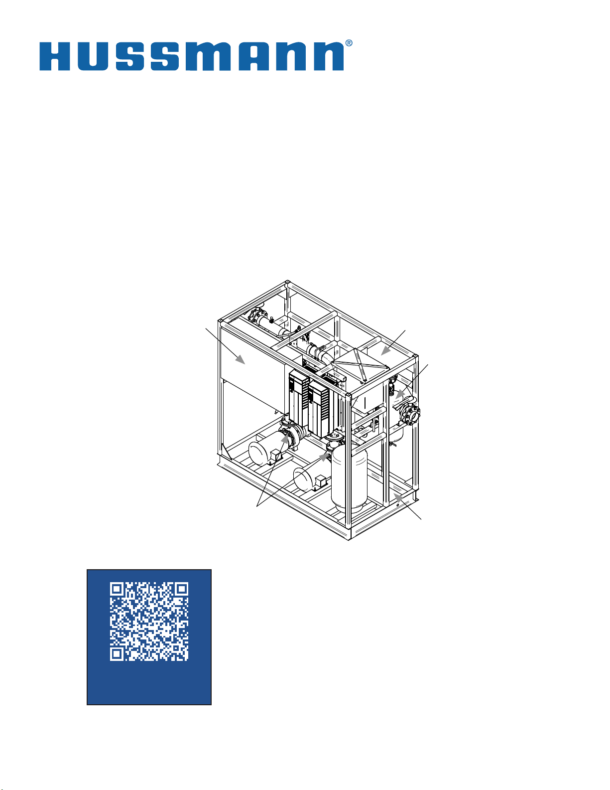
Glycol Pump Station
Medium Temperature
Secondary Glycol
Refrigeration Systems
Electrical
Control Panel
Fill Tank
Air Separator
Glycol Pumps
Drain Pan
Installation &
Operation Manual
SCAN CODE TO SEE
LATEST MANUAL
ONLINE
MANUAL- I/O PUMP STATION
1
P/N 1H24556001_E
August 2018
Page 2
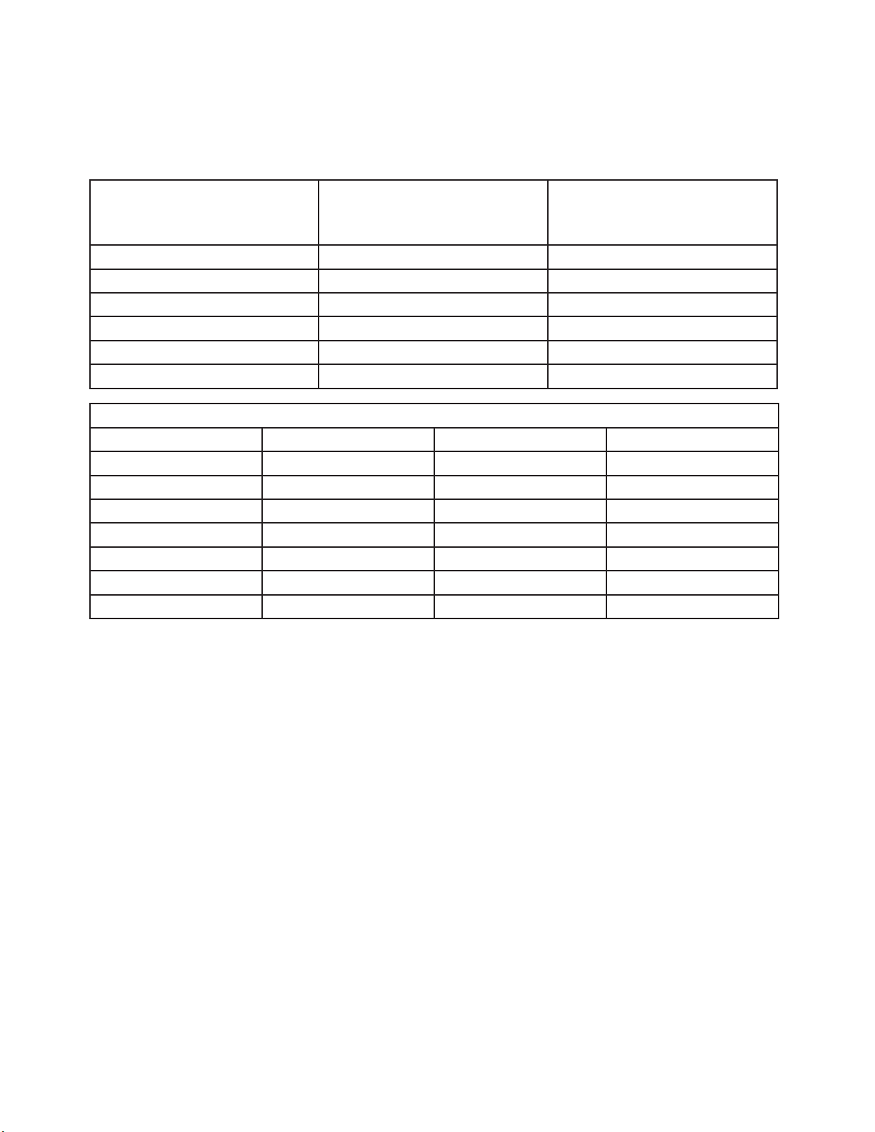
Model Reference and Flow Rates
The Pump Station model numbers, for reference:
N GS 450 K (may be followed by additional characters)
PUMP VOLTAGE
M=460/3/60
K=208-230/3/60
P=575/3/60
GLYCOL FLOW RATE (GPM)
150, 200, 250, 300, 350, 400, 450
GLYCOL SECONDARY
SYSTEM PREFIX
N=Pump Station
M=Previous Vintage
Pump Station Frame Dimensions and Weights
TABLE 1-0a: SYSTEM FRAME SIZES AND WEIGHT
August 31, 2018
This warning does not mean that Hussmann products
will cause cancer or reproductive harm, or is in
violation of any product-safety standards or
requirements. As clarified by the California State
government, Proposition 65 can be considered more of
a ‘right to know’ law than a pure product safety law.
When used as designed, Hussmann believes that our
products are not harmful. We provide the Proposition
65 warning to stay in compliance with California State
law. It is your responsibility to provide accurate
Proposition 65 warning labels to your customers when
necessary. For more information on Proposition 65,
please visit the California State government website.
2
Page 3

GLOSSARY
Refrigerant: A uid used to freeze or chill (as food) for preservation.
Primary Refrigerant: A uid such as R404A used in a vapor compression system to cool a
secondary coolant.
Secondary Coolant (Refrigerant): A uid such as Propylene Glycol used to remove
heat from cases and unit coolers and transfer the heat to the primary refrigerant through a
heat exchanger. Secondary coolants used with these systems are for medium temperature
applications only, meaning the working temperature should be above 0°F. A typical secondary
coolant supply temperature is 20°F.
Freezing Point: the temperature at which a solution begins to crystallize.
Refractometer: Device for measuring the freezing point of the secondary uid.
Triple Duty Valve: This works as a throttling valve for the secondary uid ow rate, a check
valve when the pump to which it is attached is not running and a positive shut off valve —
mounted to the pump discharge.
Pump: Device that circulates the secondary uid throughout the system.
Fill Tank: Tank used for storage of secondary uid. This tank catches overow from the pressure
relief valve and automatic air vent. Secondary uid can be added to the system using this tank
after the initial lling process has taken place.
Drain Valve: Valve to which a hose can be connected to add uid to or remove uid from the
system.
Balancing Valve: Valve used to measure and regulate the secondary coolant ow rate through
a particular section of the secondary system. Balancing valves should be multi-turn, y-pattern,
globe style valves with a positive shut off.
Air Separator: Device used to remove air from the secondary coolant.
Automatic Air Vent: Float-operated vent that allows air to escape to the atmosphere with a
minimal loss of secondary uid.
Warm Fluid Defrost: A defrost method used in lieu of an off cycle or electric defrost where
near room temperature secondary uid is circulated through the cases/unit coolers to remove ice
from the evaporator coils.
3
Page 4
SECTION 1: INSTALLATION
General Guidelines
This manual is written as a basic guideline for the installation and operation of pump stations for
both medium temperature secondary systems as well as for warm uid systems to reject heat from
water-cooled condensers. The primary refrigerant (ex. R404A) can vary depending on the customer’s
requirements. For detailed information regarding a specic component or application, contact your
Hussmann representative. Pump Stations may be installed without the use of vibration pads. The pump
station may also be anchored due to seismic concerns or if specied by the building engineer.
Additional documentation for the installation is to be provided by the customer. All components must
be installed according to manufacturer’s specications. All materials used must be compatible with the
secondary coolant. Installation must comply with ANSI/ASME B31.5 Refrigeration Piping and Heat
Transfer Components, ANSI/ASHRAE Standard 15 Safety Standard for Refrigeration Systems and local
building codes.
Inspect all components prior to installation to ensure that they are free from defects or foreign materials
and to conrm that they comply with all pressure and temperature ratings.
Shipping Damage
All equipment should be thoroughly examined for shipping damage before and while unloading.
This equipment has been carefully inspected at our factory, and the carrier has assumed responsibility for
safe arrival. If damaged, either apparent or concealed, the claim must be made to the carrier.
Apparent Loss or Damage
If there is an obvious loss or damage, it must be noted on the freight bill or express receipt and signed by
the carrier’s agent; otherwise, carrier may refuse claim. The carrier will supply the necessary claim forms.
Concealed Loss or Damage
When loss or damage is not apparent until after equipment is uncrated, a claim for concealed damage
is made. Upon discovering damage, make request in writing to carrier for inspection within 15 days and
retain all packing. The carrier will supply inspection report and required claim forms.
Pre-Installation System Cleaning
Use a 1-2% solution of trisodium phosphate (TSP), or
equivalent cleaner and distilled water to remove grease,
mill scale, or other residues from construction. Repeat
this process if necessary until the drained solution is
clear and free from visible debris. e system should
then be drained and ushed again using distilled water.
Hussmann recommends distilled water for system
ushing with 2% TSP. Dry nitrogen can be used for the
initial pressure test (60 to 75 psi) hold for three hours.
City water may be used for system cleaning if the water
meets the requirements in the table at right.
Do not let city water sit in the system. e
ushing process should be no more than 6
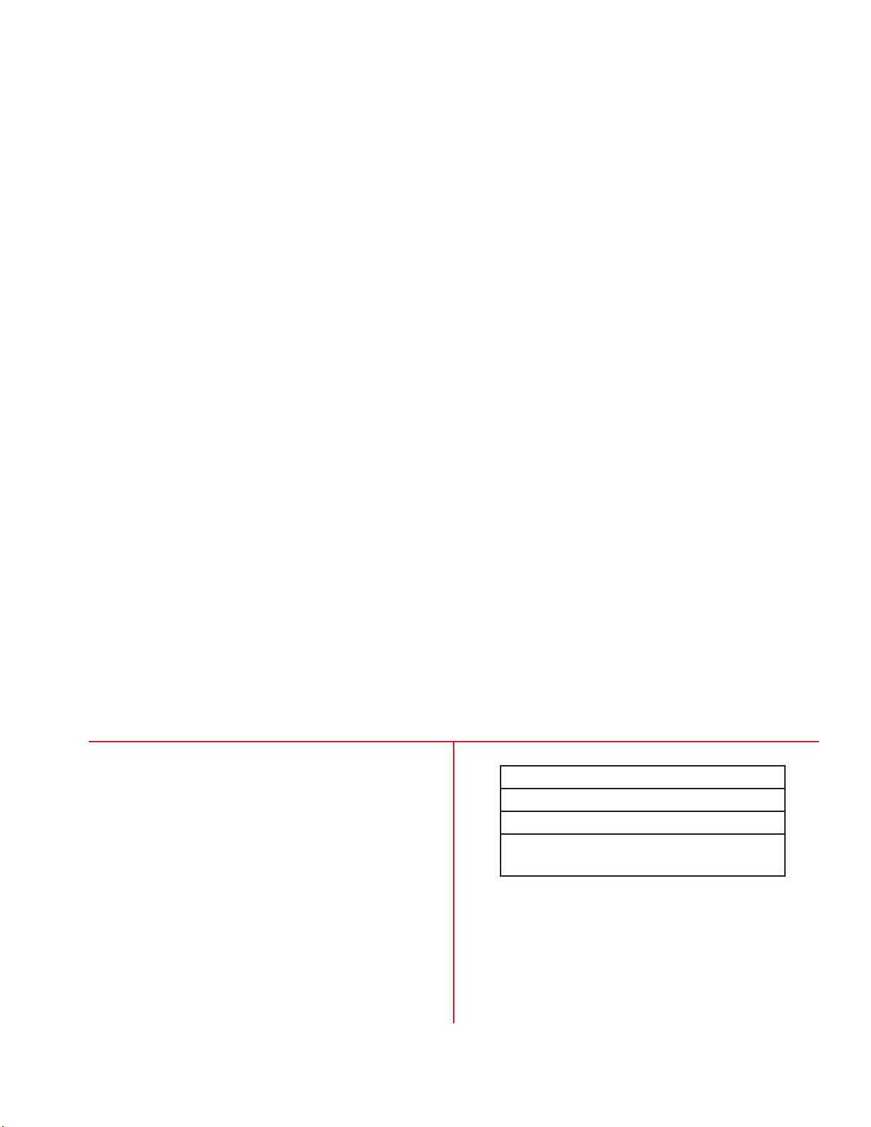
Water Quality Requirements
Impurity Level
Chlorides 25 ppm, max
Sulfates 25 ppm, max
Total Hardness,
as CaCO
Water above these levels should not be
3
introduced in the system.
to 8 hours.
80ppm
4
Page 5

SECTION 2: PIPING GUIDELINES
Piping Materials
Any piping material that meets all pressure and temperature ratings, material compatibility
requirements and state and local building codes may be used for medium temperature applications.
Connections to the rack and pump station are copper as a standard. If the other materials are used,
adapters would need to be ordered separately.
1. Plastic
a. ABS is recommended over other types for this application because of the operating
temperature.
b. ABS plastic pipe should be solvent welded (glued) together as described on the glue can.
c. Pipe ttings must be clean and dry. Cut pipe with a guillotine type cutter to get a clean, square
cut; remove any burrs. Use purple primer on both pipe and tting before gluing. Apply glue to
both pipe and tting and join with a twisting motion. Hold joint together for approximately 30
seconds to allow glue to set. Allow the joint to dry for 24 hours before putting into service.
2. Copper
a. M, K, or L may be used.
b. Copper-to-copper joints may be soft soldered or brazed so long as the braze/solder
material contains no zinc or zinc chloride. Soft solder must be used where the component
manufacturer’s installation instructions recommend.
c. Soft solder ux materials must contain no zinc and must also be water soluble.
3. Steel
a. Schedule 40 carbon steel pipe or stainless steel pipe (or tubing) are acceptable.
b. Must protect exterior from corrosion.
c. Additional system cleaning is required.
d. GALVANIZED STEEL IS NOT TO BE USED IN ANY SYSTEM CONTAINING INHIBITED
PROPYLENE GLYCOL.
Insulation
Insulation should be used in secondary system piping to reduce the heat transfer to ambient air. In
order to minimize the required insulation thickness, install pipe in air-conditioned space as much
as possible. Do not size insulation for condensation prevention only. Pipe should be insulated
according to local codes and customer specications.
When installing piping that has not been pre-insulated, there are several options for insulation.
Closed-cell elastomeric insulation is very popular in refrigeration applications. This type of
insulation can also be used in secondary system applications. For detailed information regarding
this type of insulation, visit the Armaex website at www.armaex.com.
Other types of insulation that can be used are TRYMER and Styrofoam insulation. These are
both made by Dow and are well suited for insulating pipe. Always follow the manufacturer’s
recommendations for insulation thickness and proper installation.
5
Page 6

Pipe Connections
Connecting Plastic With Metal Pipe
DO NOT THREAD PLASTIC PIPE. A compression type tting should be used. For larger pipe sizes, a
anged connection may be used.
Air Vent Valves
Manual air vent valves are recommended. Air vent valves should be located at piping high points where
air will tend to collect. Momentarily open these vents to release trapped air a few times during startup.
Provision should also be made for manual venting during the glycol loop ll. Vent valves should have a
threaded connection to facilitate connection to a pipe or hose. It is important that the automatic vents be
located in accessible locations for maintenance purposes, and that they be located where they can be
prevented from freezing. Vents will vary with materials and local codes. The lowest points of the piping
system must be purged of air, too, which typically involves heat exchanger coils.
DRAIN VALVES
Manual drain valves should be located at low points in the system or so that circuits can be drained of
most of the uid. This is used during maintenance or when changes to the system are made.
ISOLATION VALVES
Isolation valves should be used at a minimum on every circuit and as a standard on every coil. This will
allow access to each circuit without shutting down the entire system. Ball valves should be used on all line
sizes of 2” and less. Buttery valves should be used on all sizes over 2”.
FILL CONNECTIONS
Use the ll tank on the pump station to add any minor amounts of uid. Do not connect to city water.
Copper Pipe
Schrader valve air vent brazed into copper turn down. (See Figure P1.)
Plastic Pipe
After the joint is assembled, drill and tap for a threaded 1/2-ID ABS pipe to socket tting. Use ABS cement
on the threads and do not over-tighten. Install a plastic ball valve on the tting. (See Figure P2).
To provide an air trap and assure that pipe cuttings do not get into the closed loop, install the 1/2-inchthreaded-to-ABS tting in a TEE plug. Use a TEE at the turndown instead of an elbow. Install the plug and
ball valve assembly after the joint is complete. (See Figure P3.)
All
When a turndown is not going to be accessible, a remote ball valve may be used. (See Figure P4.)
Figure P1 Figure P2 Figure P3 Figure P4
6
Page 7
Pipe Supports
Suggested spacing for pipe supports is shown below. Verify state and local building codes for
required support. Piping should be supported in a manner that minimizes heat transfer to the
supports.
Nominal Pipe Size
(in)
Distance between supports
()
Schedule 40 pipe @ 100°F
Distance between supports
()
Schedule 80 pipe @ 100°F
1.0 4.5 3.5
1.5 5.0 3.5
2.0 5.0 4.0
3.0 6.0 4.5
4.0 6.5 5.0
6.0 7.5 6.0
Pipe Support Spacing, ABS-DWV, Ft.
Nominal Size 70°F 100°F 140°F
1-1/4 4-1/2 4-1/2 4
1-1/2 5 5 4-1/2
2 5 5 4-1/2
3 6 6 5-1/2
4 6-1/4 6-1/4 5-3/4
6 6-3/4 6-3/4 6
8 7 7 6-1/2
Water Loop Piping
The variations of effective water piping design and layout are numerous and a comprehensive
discussion is beyond the scope of this document. The local suppliers of pumps, pipe, valves,
cooling towers, chemicals and controls are familiar with what works best in your area.
Following are two basic design concepts applicable to water loop piping installations:
• Direct Return Piping
• Reverse Return Piping
Direct Return Piping
Direct return piping utilizes supply trunk lines. These supply lines decrease in size as branches
reduce the water ow requirements through the trunk. The return trunk lines increase in size as
branches join the trunk.
Advantages
• Initial cost of the pipe may be less than the reverse return system.
Disadvantages
• System balancing may be difficult since it must account for piping length, reductions in pipe
size, and ow requirements.
7
Page 8

Reverse Return Piping
Reverse return piping uses equal sized supply and return lines throughout the installation.
Because of the pipe layout, the head loss due to piping is nearly identical at any point
along the glycol loop.
Advantages
• This design reduces or eliminates the need for reduction ttings and allows use of
larger quantities of one size pipe.
• Little balancing of glycol ow is required. A reverse return piping system will be
essentially self-balancing.
• With proper prior planning, additional units may be added along the loop without the
need to change pipe sizes.
Disadvantages
• Initial cost of the pipe may be more than the direct return system.
Expansion Loops
Allowances for expansion and contraction in long straight runs of piping must be provided
by expansion loops.
Consult ASME B31.5 Refrigeration Piping Standard for specic design requirements. Use
horizontal expansion loops to eliminate air traps. If vertical expansion loops are required,
appropriate vent and drain valves must be installed.
Valves
1. Mount solenoid and check valves inside cases if space permits. Solenoid, check and
ball valves are to be installed upstream of the case/unit cooler heat exchangers.
2. Balancing valves are to be installed downstream of the case/unit cooler heat
exchangers. Always follow the manufacturer’s recommendations for installation. This
includes orientation, braze vs. solder, ow direction, etc. Balancing valves should
be multi-turn, y-pattern, globe style valves with a positive shut off. Adjust valves per
manufacturer’s recommendations.
NOTE: All valves are available from Hussmann.
Closed Loop Air Separator
Air separators are standard on all units. An automatic air vent is included and piped directly
out of the top of the air separator. In a circulating system, air tends to pocket where pipes
turn in a downward direction. As a result, a vent is needed at high points when lling the
closed system loop and at turn downs during start up.
See section Air Vent Valves above.
8
Page 9

SECTION 3: FIELD ELECTRICAL CONNECTIONS
Incoming Supply and Control Power
The control panel on this equipment includes disconnect switch and the standard conguration
includes a control circuit transformer with no separate 120v control power is required. Field
wiring must comply with the latest version of the NEC and state and local electrical codes.
Equipment Control Wiring
A chiller controller is integral with the secondary system controls. Individual analog and digital
inputs from the secondary system peripheral devices are required to be eld wired to the
controller board inputs of the parallel compressor rack system controller.
NOTE: The Chiller Controller and Chiller are included with the Primary Rack System.
The standard control for the pump station uses a standalone controller. This controller has
separate user documentation. This will take a dry run-enable contact. Provide a fault dry contact
to the rack controller to monitor the operation of the pump station.
Basics of Operation
When the secondary system control circuit is powered up (either 120 or 208 volts) the chiller
controller is powered. This must be programmed before starting the refrigeration system. Turn on
the main on/off switch to energize the pump. There is a time delay to allow the pump to start and
produce enough ow so that the system monitoring differential pressure does not produce an
alarm at start-up. The pump will now run continuously until the specied changeover time, when
Pump 1 will turn off and Pump 2 will turn on automatically (when in Auto Mode). There is a slight
delay at the time of this changeover to prevent slamming of the discharge check valves.
The glycol supply temperature is controlled with the rack suction pressure. The rack stages
compressors on and off based on suction pressure input. The glycol freeze thermostat
temperature and electronic expansion valve superheat settings are programmable by the user.
Warm Fluid Defrost is an optional feature specied by the customer in place of off cycle or
electric defrost (usually the latter). The temperature for the warm uid is controlled by a three
way mixing valve and temperature input in the defrost supply pipe. This temperature is controlled
between 65°F and 75°F . Refer to Johnson Controls A350P for instructions on setting the
temperature controller. A glycol solenoid receives a signal to open from the rack controller A/O
board, allowing coolant to ow through the heat exchanger. A refrigerant solenoid also receives
a signal to open, allowing refrigerant discharge gas to ow through the heat exchanger. A
differential regulator is installed in the refrigerant discharge line past the oil separator to make
sure some of the discharge gas goes through the heat exchanger.
System Faults
Pump Alarm: The system will monitor the secondary coolant ow. If the ow falls below
the setpoint (set at the factory), the pump switching function is bypassed and the controls
automatically switch from the currently active pump to the backup (when in Auto Mode). If
the backup pump is also not operating properly, the system will cause the primary refrigerant
solenoid to close and pump the rack down. The alarm must be reset manually at the control
panel after the defective pump is serviced.
9
Page 10

SECTION 4: FIELD PRESSURE TESTING
Open all ball valves, balance valves and solenoid valve
1. Close all drains and vents.
2. Isolate the expansion tank and pumps. If there are any other components within the system that are
not rated for the test pressure, isolate them as well.
3. Charge the system with dry nitrogen to 60 psig for 3 hours
4. Any leaks must be corrected. Once all leaks are stopped, system cleaning can begin.
Variable Speed Drive Programming
The VSD(s) will come factory programmed for voltage and amperage, but the pressure differential setpoint must be eld set. Record the pressure differential reading with all solenoid valves open, uid at
temperature, and ow at 100%. This is the pressure set-point for the VSD to maintain. As solenoid valves
close, the pump speed will be reduced to maintain the same pressure.
Troubleshooting for Chilled Fluid Systems:
Verify the following if it is not able to maintain the uid temperature:
• Chiller approach between 5F and 8F
• Compressors fully loaded (none operating unloaded)
• Chiller Expansion Valve superheat, not hunting and fed with solid liquid refrigerant
• Fluid solution concentration correct
• Chiller pressure drop less than 7 psi on uid side
Troubleshooting for Case Temperature Issues:
Verify the following if uid temperature is met but case temperatures are not maintained:
• Check for high loads, heavy shopping or high store temperature and humidity.
• Check for correct balance valve setting or increase setting to allow higher ow.
• Check for air trapped in coils (purge either by venting or increasing the ow
temporarily through the coil).
• Check for poor air ow through the coil.
10
Page 11

SECTION 5: PIPE SYSTEM CLEANING
With the secondary system piping installed and pressure tested with air, the piping system must
be ushed properly. Dow recommends that the new piping system should be cleaned using a 1-2%
solution of trisodium phosphate (TSP), or cleaner and water to remove grease, mill scale, or other
residues from construction. Repeat this process if necessary until the solution that is drained is
clear and free from visible debris. The system should then be drained and ushed again using
distilled water. System volume can be calculated during this stage by metering in the initial ll of the
system or by chemical analysis of cleaning chemicals after known quantities are introduced into the
system.
1. Verify that the pressure in the expansion tank is at the factory setting of 12 psig, then open all
valves, excluding drain valves.
2. Close the buttery valves at the bypass valve.
3. Connect a hose to the supply header to ll the
system with water.
4. Connect a hose to the drain valve closest to the
pump suction.
5. Fill the system and then with the ll water still
running, allow the water to drain until the drain water
becomes clear.
6. Close the drain valve and open the bypass buttery
valves.
7. Pressurize the system to approximately 30 psig (or
15 psig at highest system point.)
8. Vent the main loop lines.
9. Vent all system purge points from lowest to highest.
10. Turn off water.
11. Check to make sure the pumps are full of water.
12. Check the rotation of each pump by bumping the contactors, one at a
time.
13. Start each pump and check the amperage. This amperage should be
checked again once the triple duty valve has been adjusted. The nal
amperage may be lower than the initial reading.
14. Start one pump and allow it to run. Add water if necessary to maintain 20
psig return pressure.
15. Flush each case lineup by closing the solenoid on all other circuits for 1
minute.
16. Open all circuits and allow the system to run for at least 2 hours.
Pre-Installation System Cleaning
Use a 1-2% solution of trisodium phosphate
(TSP), or equivalent cleaner and distilled water to
remove grease, mill scale, or other residues from
construction. Repeat this process if necessary
until the drained solution is clear and free from
Total Hardness,
visible debris. The system should then be drained
and ushed again using distilled water. Hussmann
recommends distilled water for system ushing with
2% TSP. Dry nitrogen can be used for the initial
pressure test (60 to 75 psi) hold for three hours. City
water may be used for system cleaning if the water
meets the requirements as outlined in the table at
right.
11
Water Quality Requirements
Impurity Level
Chlorides 25 ppm, max
Sulfates 25 ppm, max
80ppm
as CaCO
Water above these levels should not be
Do not let city water sit in the system.
e ushing process should be
3
introduced in the system.
no more than 6 to 8 hours.
Page 12

SECTION 6: START-UP AND OPERATION
Drain the System
1. Turn off pumps.
2. Open all drain valves in the system. Purge remaining water with dry nitrogen.
3. If drain water is not clean, ush the system again.
4. Remove the cover of the suction guides and remove the start-up strainer from each. Reinstall
the run strainer before restarting.
Suction Guide
Start-up Strainer
Fill the System
1. Open all valves excluding vents and drains.
2. Check the freezing point of each container of secondary uid with a refractometer. For 35%
glycol, the freezing point should be 2°F.
3. Pump the pre-mixed uid into the system.
4. Use the same air purge process as previously described.
5. Place any purged secondary uid in the ll tank.
6. Make sure all air has been removed from the pumps.
7. Open the triple duty valves.
8. Restart one of the pumps.
9. Maintain 20 psig return pressure by adding secondary uid as necessary. When using the ll
tank, ll the tank up to the overow (but not above). Open the ball valve between the tank and
the pump suction. Allow the pump to pull the uid into the system, making sure not to allow in
any air. Close the valve when the pump no longer pulls in uid or the uid level nears the bottom
of the tank. If 20 psig is not attained, add more uid.
10. Fill each case line-up completely by closing the solenoid on all other circuits for 1 minute.
11. Check the freezing point of the system using a refractometer after the uid has been circulated.
12. Allow the system to circulate for 1 hour.
12
Page 13

System Fluids
Never mix uids from different manufacturers. Do not use
concentrated uid. Use only premixed (prediluted) uid.
A small amount of concentrate should be kept on hand to allow
for adjustment to the solution during startup. A refractometer,
calibrated for uids at room temperature, is used to measure
dilution. Hussmann recommends using distilled water. Do not
use city water.
Inhibited propylene glycol used in the system must be approved
for use by the FDA.
Hussmann recommends using Intercool P-323AA inhibited
propylene glycol, specically formulated for aluminum tubing.
Only use pre-diluted solutions (35% inhibited propylene glycol).
Dowfrost may be used, but pH must be maintained and / or
adjusted.
Interstate Chemical Company Inc.
2797 Freedland Rd.
Hermitage, PA 16148
1 (800) 422-2436
Requirements for system uid:
Pre-mixed 35% inhibited propylene glycol
pH of solution 7.0 to 8.0.
DO NOT INSTALL AUTOMATIC MAKEUP.
Set Balance Valves (Field Installed)
1. Once the system has been lled, turn on the primary refrigeration. Coolant may need to be
added, since the uid will contract.
2. Set each balance valve at the ow rate on the store legend.
3. Use the manufacturer’s recommendations for setting the valves.
Set End of Loop Balance Valve (Field Installed, typically only on cold uid systems)
After setting the triple duty valve and balance valves throughout the system, nd the pressure at
the supply header while all case line-ups and cooling units are in cooling mode. This will be the
“normal” system pressure. Set the end of loop balance valve for 20gpm while all case line-ups and
cooling units are in cooling mode.
Pump Maintenance
IMPORTANT: Follow the lubrication procedures recommended by the pump and pump motor
manufacturer. Check the lubrication instructions supplied with the pump and motor for the particular
frame size indicated on the motor nameplate.
13
Page 14

(GLYCOL SYSTEM PIPING GUIDELINES)
%PG Burst
°F °C °F °C °F
0 32 0 212 100
5 29.1 -1.6 212 100
10 26.1 -3.3 212 100 23
15 22.9 -5.1 212 100 17
20 19.2 -7.1 213 101 11
22 17.6 -8 213 101 7
24 15.6 -9.1 213 101 3
26 13.7 -10.2 214 101 -2
28 11.5 -11.4 215 102 -7
30 9.2 -12.7 216 102 -14
32 6.6 -14.1 216 102 -22
34 3.9 -15.6 216 102 -28
36 0.8 -17.3 217 103 -37
38 -2.4 -19.1 218 103 -37
40 -6 -21.1 219 104 -37
42 -9.8 -23.2 219 104
44 -13.9 -25.5 219 104
46 -18.3 -27.9 220 104
48 -23.1 -30.6 221 105
50 -28.3 -33.5 221 105
Freezing Point
Boiling Point
PROPYLENE GLYCOL PROPERTIES
Propylene glycol (PG): Very high viscosity at low temperatures; less toxic than ethylene
glycol; risk of environmental pollution; most commercial products for indirect heat pump
and refrigeration systems have good corrosion protection.
PG is a colorless, odorless liquid that is generally recognized as safe by the U.S. Food
and Drug Administration (FDA) in 21 CFR § 184.1666, for use as a direct food additive
under the conditions prescribed.
PG is used in cosmetics and in pharmaceuticals. PG has a wide range of practical
applications such as antifreezes, coolants and aircraft deicing uids; heat transfer
and hydraulic uids; solvents; food; avors and fragrances; personal care products;
plasticizers; and thermoset plastic formulations.
PG is not acutely toxic (single dose, high exposure). It is essentially non-irritating to the
skin and mildly irritating to the eyes. Numerous studies support that PG is not a skin
sensitizer or a carcinogen.
Typical freezing, boiling and burst points of propylene
glycol solutions
14
Page 15

Temp °F 20 25 30 35 40 45 50
10 65 65.3 65.6 65.85 66.11
15 64.95 65.25 65.54 65.79 66.04
20 64.23 64.56 64.9 65.19 65.48 65.73 65.97
25 64.18 64.51 64.85 65.13 65.41 65.65 65.89
30 64.14 64.47 64.79 65.07 65.35 65.58 65.82
Temp °F 20 25 30 35 40 45 50
10 0.898 0.8785 0.859 0.8365 0.814
15 0.9 0.88075 0.8615 0.83925 0.817
20 0.936 0.919 0.902 0.883 0.864 0.842 0.82
25 0.937 0.9205 0.904 0.885 0.866 0.84425 0.8225
30 0.938 0.922 0.906 0.887 0.868 0.8465 0.525
Temp °F 20 25 30 35 40 45 50
10 0.228 0.2165 0.205 0.194 0.183
15 0.23 0.21825 0.2065 0.1955 0.1845
20 0 0.116 0.232 0.22 0.208 0.197 0.186
25 0.132 0.18275 0.234 0.22175 0.2095 0.19825 0.187
30 0.263 0.2495 0.236 0.2235 0.211 0.1995 0.188
Temp °F 20 25 30 35 40 45 50
10 13.42 20.205 26.99 33.805 40.62
15 11.655 17.2 22.745 28.485 34.225
20 5.36 7.625 9.89 14.195 18.5 23.165 27.83
25 4.795 6.735 8.675 12.2425 15.81 19.775 23.745
30 4.23 5.845 7.46 10.29 13.19 16.39 19.66
% Propylene Glycol
Specific Heat (BTU/lb. °F)
% Propylene Glycol
Thermal Conductivity (BTU/(hr*ft2 )(°F/ft)
% Propylene Glycol
Viscosity (cps)
% Propylene Glycol
Density (lb./cu.ft)
It is recommended that a minimum of 30% by volume of fully inhibited, industrial grade propylene glycol
with water be used on the condensing side, while 35% by volume propylene glycol be used on the evaporator
side.
NOTE: Do not mix like or unlike uids from different manufacturers. Do not use automotive grade glycols
15
Page 16

System Fluids
Never mix uids from different manufacturers. Do not use concentrated uid. Use only premixed
(pre-diluted) uid. A small amount of concentrate should be kept on hand to allow for adjustment
to the solution during startup. A refractometer, calibrated for uids at room temperature, is used to
measure dilution. Hussmann recommends using distilled water. Do not use city water.
Inhibited propylene glycol used in the system must be approved for use by the FDA.
Hussmann recommends using Intercool P-323AA inhibited propylene glycol, specically formulated
for aluminum tubing. Only use pre-diluted solutions (35% inhibited propylene glycol). Dowfrost may
be used, but pH must be maintained and / or adjusted.
Interstate Chemical Company Inc.
2797 Freedland Rd.
Hermitage, PA 16148
1 (800) 422-2436
Requirements for system uid:
Pre-mixed 35% inhibited propylene glycol
pH of solution 7.0 to 8.0.
DO NOT INSTALL AUTOMATIC MAKEUP.
Set Balance Valves (Field Installed)
For cold uid systems, additional uid may need to be added after the chillers bring down the
temperature. Maintain approximately 15 psig at the highest point in the system. Record the
pressure and temperature at the pump station (in the store log book).
Case balance valves may be set at the ow rate shown on the store legend. Use the balance valve
setting charts to estimate the ow rate for each valve (measuring pressure across each valve).
After setting all valves and running the chilled uid at nal temperature, verify that solenoid valves
are not cycling too much or too little on any circuit. It is recommended to verify the circuit cycling
again after the store has been opened since ow rates are estimated based on standard conditions.
Record the actual valve settings of each circuit balance valve and record.
Set End of Loop Balance Valves (Field Installed, typically only on cold uid systems)
After setting the triple duty valve and balance valves throughout the system, nd the pressure at the
supply header while all case line-ups and cooling units are in cooling mode. This will be the normal
system pressure. Set the end of loop balance valve for 20gpm while all case lineups and cooling
units are in cooling mode.
Pump Maintenance
IMPORTANT: Follow the lubrication procedures recommended by the pump and pump motor
manufacturer. Check the lubrication instructions supplied with the pump and motor for the particular
frame sixe indicated on the motor name plate
16
Page 17

Balancing Valve — Secondary Fluid Ship Loose
Curve 1: Armstrong Balancing Valve - Flow Rates and Pressure Drop
17
Page 18

18
Page 19

19
Page 20

20
Page 21

Typical Pump Station Dimensions
91.00
REAR ACCESS REQUIRED
FOR STRAINER REMOVAL
46.25
ELECTRICAL
CONTROL PANEL
FILL TANK
DISCHARGE
CONNECTION
78.00
64.88
82.00
SINGLE
VSD, STANDARD
BACK-UP
VSD, OPTIONAL
SUCTION
CONNECTION
50.88
EXPANSION TANK
80.08
44.00
DRAIN PAN
SUCTION
CONNECTION
PUMP STATION GUIDE
WITH START-UP STRAINER
(MUST BE ACCESSIBLE)
21
Page 22

22
Page 23

23
Page 24

24
Page 25

25
Page 26

26
Page 27

27
Page 28

28
Page 29

29
Page 30

To obtain warranty information
or other support, contact your
Hussmann representative.
Please include the model and
serial number of the product.
Hussmann Corporation, Corporate Headquarters: Bridgeton, Missouri, U.S.A. 63044-2483 01 October 2012
 Loading...