

Page 1
NAV & NAVC
®
Medium Temperature
Service Deli Self Contained
Merchandisers
IMPORTANT
Keep in store
for future reference!
MANUAL- IO NAV/NAVC SC
Installation &
Operation Manual
P/N 2400204_G
July 2015
Spanish 0531301
French 0531302
Page 2

Page 3
P/N 2400204_G iii
Merchandiser must operate for 24 hours
before loading product!
Regularly check merchandiser temperatures.
Do not break the cold chain. Keep products in
cooler before loading into merchandiser.
These merchandisers are designed for
pre-chilled products only.
IMPORTANT
KEEP IN STORE FOR FUTURE REFERENCE
Quality that sets industry standards!
12999 St. Charles Rock Road • Bridgeton, MO 63044-2483
U.S. & Canada 1-800-922-1919 • Mexico 1-800-890-2900
www.hussmann.com
© 2015 Hussmann Corporation
Page 4

Page 5

TABLE OF CONTENTS v
ANSI DEFINITIONS ................. vi
INSTALLATION
Certification
Hussmann Product Control
Shipping Damage
Location
Self Contained (Location)
Model Description
Unloading
Exterior Loading
Shipping Skid
Merchandiser Leveling
Optional Legs
Serial Plate Location
........................ 1-1
........... 1-1
................... 1-1
........................... 1-1
............. 1-2
.................. 1-3
......................... 1-3
.................... 1-3
...................... 1-4
............... 1-4
...................... 1-4
................. 1-4
Light Switch . . . . . . . . . . . . . . . . . . . . . . . . 1-4
Refrigeration Unit Access
Sealing Merchandiser to Floor
Checklist
.......................... 1-5
............. 1-4
......... 1-4
MAINTENANCE
Care and Cleaning ................... 4-1
Do NOT Use:
Do:
............................... 4-1
Cleaning Stainless Steel Surfaces
Cleaning Pencil Thermometer
Cleaning the Bottom Deck
Cleaning Coils
Cleaning Evaporation Pan
Removing Scratches from Bumper
Maintaining Fluorescent Lamps
...................... 4-1
....... 4-2
......... 4-2
............ 4-2
...................... 4-3
............ 4-3
...... 4-5
........ 4-6
SERVICE
Replacing Fluorescent Lamps
Troubleshooting Guide
............... 5-1
Troubleshooting Light Guide
......... 5-1
.......... 5-2
APPENDIX
ELECTRICAL / REFRIGERATION
Merchandiser Electrical Data
Field Wiring
........................ 2-1
.......... 2-1
Electrical Connections . . . . . . . . . . . . . . . . 2-1
Power Input
Electrical Outlet
Refrigeration (Self Contained)
Waste Outlet
Electromechanical Controls
Defrost Time Clock
Setting Defrost Times
Temperature Control
........................ 2-1
..................... 2-1
......... 2-2
....................... 2-2
........... 2-3
.................. 2-3
................ 2-4
................ 2-4
START UP / OPERATION
Start-Up
Controls and Adjustments
Load Limits
Stocking
Shelf Maximum Weight Limits
Pencil Thermometer
........................... 3-1
............ 3-1
........................ 3-2
........................... 3-2
......... 3-3
................. 3-4
Part Numbers
Plan Views
Cross Sections and Refrigeration Data
Electrical Data
..................... A-1
........................ A-3
.. A-5
..................... A-6
Shipping Weights and Amps . . . . . . . . . . A-7
Wiring Diagrams
................... A-8
WARRANTY
HUSSMANN CORPORATION • BRIDGETON, MO 63044-2483 U.S.A.
Service Deli Merchandisers
Page 6
vi
REVISION HISTORY
REVISION G — Changed ambient temp in box; 1-1
iii — changed to pre-chilled; Added Section 2 Safe-NET;
3-1 Controls and Adjustments Table; 5-1 LED lamps;
A-5 Defrost Data; A-6 lamp data; Energy Consumption
A-7; New Wiring Diagram and Parts List
REVISION F — Added Checklists Page 1-7; Added
Warning Page 1-3; Cleaning Coils 4-3; Maintaining
Fluorescent Lights 4-4, Checklist Page, 4-6
REVISION E — JANUARY 2011
1. Added Location Drawing, Page 1-2
2. Added Light Switch, Refrigeration Unit Access,
Page 1-4
3. Added Appendix A, Technical Data
* * * * * * * * * * * * * * * * * * * * * * * * * *
ANSI Z535.5 DEFINITIONS
• DANGER – Indicate[s] a hazardous
situation which, if not avoided, will
result in death or serious injury.
• WARNING – Indicate[s] a hazardous
situation which, if not avoided, could
result in death or serious injury.
• CAUTION – Indicate[s] a hazardous
situation which, if not avoided, could
result in minor or moderate injury.
• NOTICE – Not related to personal injury –
Indicates[s] situations, which if not avoided,
could result in damage to equipment.
P/N 2400204_G U.S. & Canada 1-800-922-1919 • Mexico 1-800-890-2900 • www.hussmann.com
Page 7
P/N 2400204_G 1-1
INSTALLATION
CERTIFICATION
These merchandisers are manufactured to
meet ANSI / National Sanitation Foundation
®
(NSF
) Standard #7 requirements. Proper
installation is required to maintain certification.
Near the serial plate, each case carries a label
identifying the type of application for which
the case was certified.
ANSI/NSF-7 Type I - Display Refrigerator / Freezer
Intended for 75°F / 55% RH Ambient Application
ANSI/NSF-7 Type II - Display Refrigerator / Freezer
Intended for 80°F / 55% RH Ambient Application
ANSI/NSF-7 - Display Refrigerator
Intended for Bulk Produce
HUSSMANN PRODUCT CONTROL
The serial number and shipping date of all
equipment is recorded in Hussmann’s files
for warranty and replacement part purposes.
All correspondence pertaining to warranty or
parts ordering must include the serial number
of each piece of equipment involved. This is
to ensure the customer is provided with the
correct parts.
Apparent Loss or Damage
If there is an obvious loss or damage, it must
be noted on the freight bill or express receipt
and signed by the carrier’s agent; otherwise,
carrier may refuse claim.
Concealed Loss or Damage
When loss or damage is not apparent until
after equipment is uncrated, retain all packing
materials and submit a written response to the
carrier for inspection within 15 days.
LOCATION
These merchandisers are designed for
displaying products in air conditioned stores
where temperature is maintained at or below
the ANSI / NSF-7 specified level and relative
humidity is maintained at or below 55%.
Recommended operating ambient
temperature is between
65°F (18°C) and 75°F (23.9°C).
Maximum relative humidity is 55%.
SHIPPING DAMAGE
All equipment should be thoroughly
examined for shipping damage before and
during unloading. This equipment has been
carefully inspected at our factory. Any claim
for loss or damage must be made to the
carrier.
The carrier will provide any necessary
inspection reports and/or claim forms.
HUSSMANN CORPORATION • BRIDGETON, MO 63044-2483 U.S.A.
Placing refrigerated merchandisers in direct
sunlight, near hot tables or near other heat
sources could impair their efficiency. Like
other merchandisers, these merchandisers are
sensitive to air disturbances. Air currents
passing around merchandisers will seriously
impair their operation. Do NOT allow air
conditioning, electric fans, open doors or
windows, etc. to create air currents around
the merchandiser.
Service Deli Merchandisers
Page 8
1-2 InstallatIon
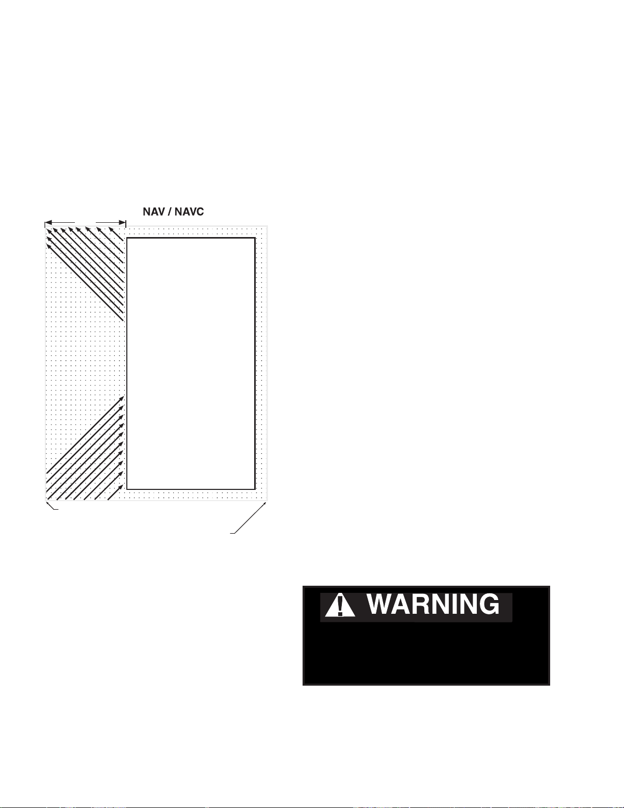
SELF CONTAINED (LOCATION)
NAV and NAVC merchandiser models have
front-facing condenser air intake and air
discharge. Maintain a minimum clearance
distance of 2 feet in front of the merchandiser
and 4 inches on each side, so that air discharge
and air intake are not obstructed.
24 in.
Air
Exhaust
Front
Air
Intake
R ear
MODEL DESCRIPTION
NAV/C service deli merchandisers offer
versatility in the display of medium
temperature (32º F to 41º F) products such
as dairy products, prepared salads, pizza and
fresh dinners that are pre-chilled in a cooler.
Carefully read and follow the instructions
before operating the merchandiser.
UNLOADING
Unloading from Trailer:
Lever Bar (also known as a Mule, Johnson
Bar, J-bar, Lever Dolly, or Pry Lever)
Move the merchandiser as close as possible to
its permanent location and remove all packaging.
Check for damage before discarding packaging.
Remove all separately packed accessories
such as kits and shelves. Improper handling
may cause damage to the merchandiser when
unloading. To avoid damage:
Maintain 24 in. Clearance
at Front
Maintain 4 in. Clearance
around Sides and R ear
1. Do not drag the merchandiser out of the
trailer. Use a Johnson Bar, J-bar, Lever
Dolly, or Pry Lever)
2. Use a forklift or dolly to remove the
merchandiser from the trailer.
Do NOT stand or walk on top of
merchandiser. Do not store items or
ammable materials atop the unit.
P/N 2400204_G U.S. & Canada 1-800-922-1919 • Mexico 1-800-890-2900 • www.hussmann.com
Page 9
P/N 2400204_G 1-3
EXTERIOR LOADING
Do NOT walk on top of merchandisers or
damage to the merchandisers and serious
personal injury could occur.
Do NOT remove shipping crate until
the merchandiser is positioned
merchandisers are not structurally
designed to support external loading
such as the weight of a person. Do not place
MERCHANDISER LEVELING
for installation.
heavy objects on the merchandiser.
Be sure to position merchandisers
properly. Level the merchandiser by all four
SHIPPING SKID
corners. Merchandiser(s) must be installed
level to ensure proper operation of the
Each merchandiser is shipped on a skid to
protect the merchandiser’s base, and to make
refrigeration system, and to ensure proper
drainage of defrost water.
positioning the case easier.
Do not remove the shipping skid until the
merchandiser is near its final location.
The skid provides protection for both the
merchandiser and the floor.
Remove the skid by raising one end of the
merchandiser approximately 6 inches. Block
the merchandiser securely, and remove the two
skid bolts from the raised end. Replace the
bolts with (provided) leg levelers. Repeat this
procedure at opposing end. Once the leg levelers
are secured in place, the merchandiser may be
slid off the skid and placed in its final location.
DO NOT TILT MERCHANDISER ON ITS
SIDE OR END WHEN REMOVING SKID.
Once the skid is removed, the merchandiser
must be lifted —NOT PUSHED— to reposition.
Check floor where merchandisers are to be set
to see if it is a level area. Determine the highest
part of the floor.
EVAPORATO R
COIL
CONDENSING
UNIT
OPTIONAL LEGS
®
NSF
approved legs replace the leg levelers if
required by local health codes. The legs raise
the case 6 inches for cleaning purposes. An
optional skirt kit can be provided to snap on
the legs.
HUSSMANN CORPORATION • BRIDGETON, MO 63044-2483 U.S.A.
Service Deli Merchandisers
Page 10
1-4 InstallatIon
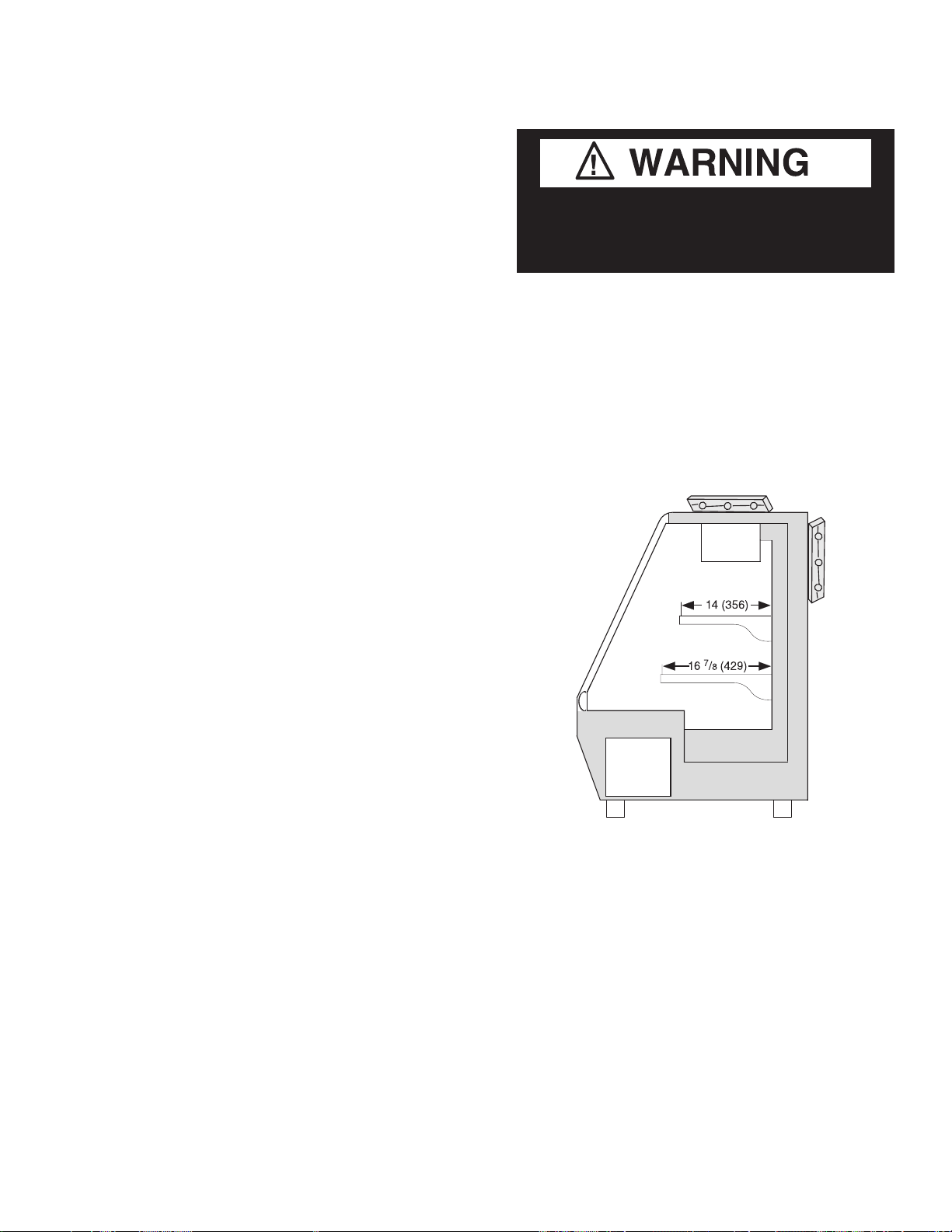
SERIAL PLATE LOCATION
The serial plate is located in the top interior at
the left side of the merchandiser. It contains all
pertinent information such as model, serial
number, amperage rating, refrigerant type
and charge. This information will be needed
to maintain, service or order parts for the
merchandiser.
Serial Plate
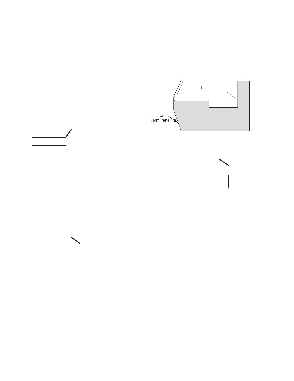
REFRIGERATION UNIT ACCESS
The lower front panel may be removed by
lifting the panel upward and over the tabs on
which it is hanging. The panel is replaced by
reversing the above procedure.
Then
LIGHT SWITCH
The light switch is located at the rear of the
merchandiser. Ensure it is switched ON to turn
on the display lights.
Light Switch
Lift up and
out to remove
access panel
First
SEALING MERCHANDISER TO FLOOR
If required by local sanitary codes, or if the
customer desires, merchandisers may be sealed
to the floor using a vinyl cove base trim. The
size needed will depend on how much variation
there is in the floor, from one end of the
merchandiser to the other. Sealing of the lower
front and rear panels on self contained models
may hamper their removal for servicing or
maintenance of the condensing unit.
NOTE: Do not allow trim to cover any intake
or discharge grilles located in the lower front
panel.
P/N 2400204_G U.S. & Canada 1-800-922-1919 • Mexico 1-800-890-2900 • www.hussmann.com
Page 11
P/N 2400204_G 1-5
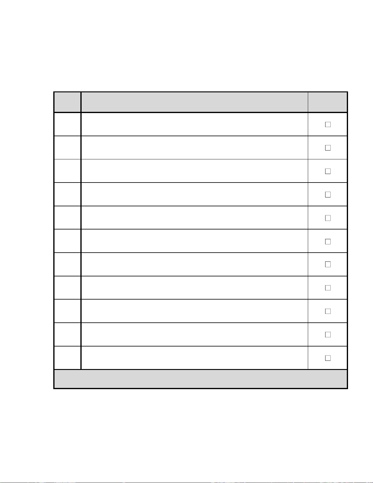
Hussmann Self-Contained Refrigeration Equi pment Sta rt Up Check List
***Please note that failure to follow this start-up document may void your factory warranty***
Form HSCW01 Rev. 30MAY12 P/N 0525209_B
Step Startup Activity Check
1
Locate, read and maintain install/operation manual in a safe place for
future reference.
2 Examine unit. Confirm there is NO damage or concealed damage.
3 Level the unit, side to side and front to rear.
4 Remove all shipping brackets/compressor straps/bolts etc.
5
Unit must be run on a dedicated electrical circuit without the use of
an extension cord.
6
Ensure that the proper electrical requirements for the equipment are
supplied.
7 Verify field electrical connections are tight.
8
Verify all electrical wiring is secured and clear of any sharp edges or
hot lines.
9 Verify the condensate drain line is properly trapped and pitched.
10 Verify all required clearances on the sides and back of unit.
11
Verify there are no air disturbances external to the unit. Heat and air
registers, fans, and doors etc.
Advise owner/operator that merchandiser must operate at temperature for 24 hrs prior to loading
with product.
LEGAL DISCLAIMER:
Hussmann shall not be liable for any repair or replacements made without the written consent of Hussmann, or w hen the productis installed or operated in a manner
contrary to the printed instructions covering installation and service which accompanied such product.
HUSSMANN CORPORATION • BRIDGETON, MO 63044-2483 U.S.A.
Service Deli Merchandisers
Page 12

1-6 InstallatIon
P/N 2400204_G U.S. & Canada 1-800-922-1919 • Mexico 1-800-890-2900 • www.hussmann.com
Page 13
P/N 2400204_G 2-1
ELECTRICAL / REFRIGERATION
MERCHANDISER ELECTRICAL DATA
Refer to Appendix A of this manual or the
merchandiser’s serial plate for electrical
information.
FIELD WIRING
Field wiring must be sized for component
amperes stamped on the serial plate. Actual
ampere draw may be less than specified.
ALWAYS CHECK THE SERIAL PLATE
FOR COMPONENT AMPERES
ELECTRICAL CONNECTIONS
All wiring must be in compliance with NEC
and local codes.
ELECTRICAL OUTLET:
Before the merchandiser is connected to any
wall circuit, use a voltmeter to check that the
outlet is at 100% of the rated voltage. The wall
circuit must be dedicated for the merchandiser. Failure to do so voids the warranty. Do
not use an extension cord. Never plug in more
than one merchandiser per electrical circuit.
• Always use a dedicated circuit with the
amperage stated on the unit.
• Plug into an outlet designed for the plug.
• Do not overload the circuit
• Do not use long or thin extension cords.
Never use adapters.
• If in doubt, call an electrician.
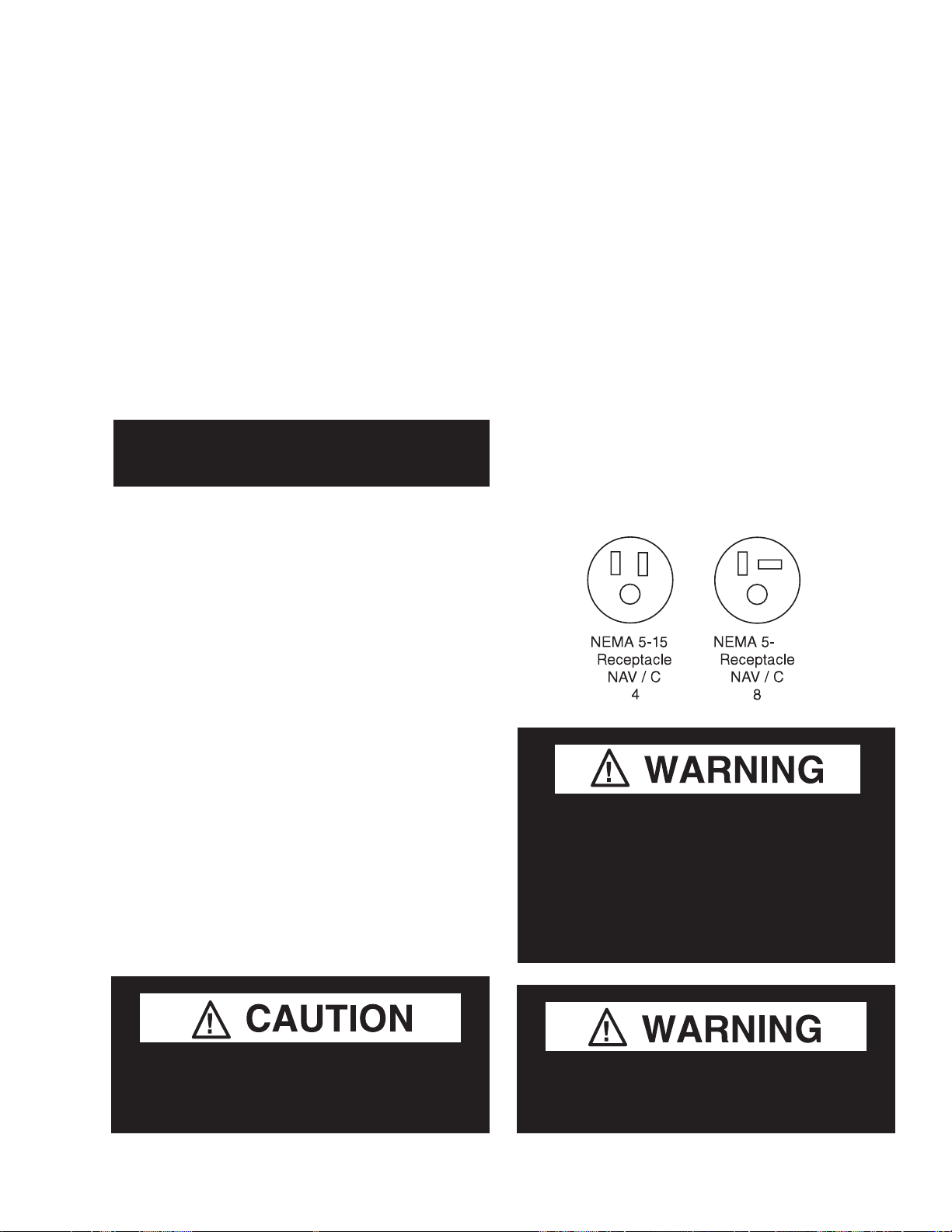
POWER INPUT
NAV / NAVC merchandisers are provided
with 3-Amp power receptacles. E
equipment connected to the receptacle
must not exceed 3 amps. The receptacle is in
lectrical
series with a GFCI safety device.
NAV / NAVC merchandisers do not have a
power switch. Once power cord is connected
to power, the merchandiser is energized.
The refrigeration thermostat has an OFF
position that disconnects power to the
condensing unit only.
Risk of Electric Shock. If cord or plug
becomes damaged, replace only with
a cord and plug of the same type.
R
6 &
20R
— LOCK OUT / TAG OUT —
To avoid serious injury or death from electrical shock, always disconnect the electrical
power at the main disconnect when servicing
or replacing any electrical component. This
includes, but is not limited to, such items as
doors, lights, fans, heaters, and thermostats.
Merchandiser must be grounded.
Do not remove the power supply cord ground.
HUSSMANN CORPORATION • BRIDGETON, MO 63044-2483 U.S.A.
Service Deli Merchandisers
Page 14

2-2 ELECTRICAL / REFRIGERATION
REFRIGERATION
(Self Contained Models)
Each self contained model is equipped with
its own condensing unit and control panel
located beneath the display area. The correct
type of refrigerant will be stamped on each
merchandiser’s serial plate. The merchandiser refrigeration piping is leak tested. The
unit is charged with refrigerant, and shipped
from the factory with all service valves open.
NAV/C models have a refrigeration system
that uses a hermetic compressor and a
capillary tube for refrigerant control. The
capillary tube is soldered to the suction line
pull-out coil for proper heat exchange. If the
capillary should become plugged or damaged, it
is best to replace the heat exchanger.
WASTE OUTLET
For self contained models like NAV / NAVC,
condensate waste from defrost, drains into a
condensate pan located beneath the merchandiser.
The condensate pan has a hot gas loop that
evaporates waste. Ensure the drain hose is
properly trapped, and the drain area is not
clogged. Ensure waste outlet cap is fitted
securely in place.
Refrigeration lines are under pressure.
Refrigerant must be recovered before
attempting any connection or repair.
When brazing pipes, be sure to use the
insulation blanket shipped with the
merchandiser to prevent damage to the
metal merchandiser bottom.
Product will be degraded and may spoil if
allowed to sit in a non-refrigerated area.
Waste Outlet
NOTE: All lower base panels must be in place
when the merchandiser is operating. If not, airflow from the condenser will be directed over the
evaporator pan and defrost waste in the pan may
overflow.
P/N 2400204_G U.S. & Canada 1-800-922-1919 • Mexico 1-800-890-2900 • www.hussmann.com
Page 15

P/N 2400204_G 2-3
OPERATING Safe-NET III CONTROLS
The temperatures can be adjusted by rotating
The Safe-NET III electronic temperature and
defrost controller is located in the cassette
compartment. The controller comes factory set
at position #5 and is ready to go.
the knob counter-clockwise for a warmer set-
point, or clockwise for a colder setpoint. The
display shows the setpoint for a few seconds
when changed, then reverts to showing the
sensed temperatures in the merchandiser.
The front grille must be removed in order to
access this control. When removing the grille
for this operation or for condenser cleaning,
care must be taken not to damage the display
interface cable. It may be unplugged during
this task.
The adjustment knob allows the user to select
a pre-configured cold setpoint, warm setpoint
or any setpoint within this range. The adjust-
ment knob is also configured with
off/on
functionality to power off the controller. The
off position shuts off the compressor only.
UNPLUG THE UNIT FOR SERVICE.
Position #5
Remove Plastic Screws
The top, or green, LED indicates the case is in
refrigeration mode. The center, or yellow, LED
indicates the case is in defrost mode. The bottom (red) LED indicates an alarm condition,
such as merchandiser warming up because the
door is not closed.
HUSSMANN CORPORATION • BRIDGETON, MO 63044-2483 U.S.A.
Compressor
Powered on
GREEN
Defrost Cycle
YELLOW
Alarm
RED
Off / On Position
Safe-NET III Indicators
Service Deli Merchandisers
Page 16

2-4 ELECTRICAL / REFRIGERATION
START-UP / OPERATION
The defrost cycle is initiated at power on. (This
cycle will quickly terminate on the initial startup of a warm merchandiser.) Another defrost
cycle will follow every 8 hours thereafter. The
defrost times will reset whenever power is interrupted. Therefore, the standard defrost times
can be reset by interrupting power (full stop,
then start) at the desired time. This will reset
the initial time and restart the 8-hour cycle.
During the compressor-on time (1 minute),
or compressor-off time (2 minutes), built-in
protection time will delay the defrost initiation.
Troubleshooting
If you force a defrost cycle during this time,
the feature will initiate but not start until the
compressor protection mode times out.
ALARMS AND CODES
Safe-NET III is available with an audible
alarm (located in the display module) that
sounds in the event a failure occurs.
flashing temperature or sensor alarm
led, e1 or e2
If the Temperature or Sensor Alarm LED (red)
on the controller and display is flashing, a
temperature sensor has failed (or sensor is
disconnected). The display shows E1 if the case
sensor has failed (or disconnected) or E2 if the
evaporator sensor has failed (it is disconnected).
If the merchandiser sensor fails, refrigeration
will run continuously. Turn off, or repeat a
duty cycle of a few minutes on and a few
minutes off.
Alarm
or Code Indicates Action
Red LED • Firmware • Call Service
remains ON corruption on immediately
after startup controller
• Controller is
not operating
Red LED turns • Case • Make sure the door
on during temperature is closed
operation is too warm • Make sure that cold
or too cool air is not being
blocked or deflected
• Check the
temperature using
the optional display
or a thermometer
• If the LED does not
turn off after on hour,
call Service
Red LED • Temperature • Check the optional
flashes sensor failure display for error code
• E1 indicates E1 or E2 and call
a case Service immediately
temperature
failure
• E2 indicates
an evaporator
temperature
sensor failure
P/N 2400204_G U.S. & Canada 1-800-922-1919 • Mexico 1-800-890-2900 • www.hussmann.com
Page 17

P/N 2400204_G 2-5
4
DEFROST TERMINATION SWITCH
Merchandisers may use a defrost termination
switch, instead of an evaporator sensor to
terminate a defrost cycle. The defrost
termination switch is temperature activated
and senses the completion of defrost.
Compressor
Off Time If
Sensor Failed
On
Compressor or
Refrigeration
Status
Off
Off
MANUAL DEFROST
Note:
This procedure initiates
a manual or forced
defrost.
Compressor
On Time If
Sensor Failed
On
Off
5
3
2
1
I
Warm
1.
Warm
Rotate knob fully
2.
counterclockw ise
until it stops (full
Warm
3.
After 10 seconds, but
before 20 seconds,
rotate knob fully
clockw ise until it
stops (full cold position)
Cold
Note location of
knob setting
4
5
3
2
1
I
Cold
4
5
3
2
1
I
Cold
On
Time
6
7
I
6
7
I
6
7
I
IMPORTANT:
Return the control knob to its original setting
(Step 1) once the manual defrost has been initiated.
HUSSMANN CORPORATION • BRIDGETON, MO 63044-2483 U.S.A.
Service Deli Merchandisers
Page 18

2-6 ELECTRICAL / REFRIGERATION
4
5
3
2
1
6
7
COLDWARM
Display - at Full Cold
Model LTH
"OFF" Position
Safe-NET III Control
# 1 Position
Safe-NET III Control
Set at Full Cold Position
4
5
3
2
1
6
7
COLDWARM
TEMPERATURE ADJUSTMENT
1. Rotate the adjustment knob counter clock-
wise for a warmer setpoint or clockwise for
a colder setpoint.
2. While adjusting the temperature, the display
shows the setpoint (cut out value). A few
seconds after the temperature is set, the
controller reverts to the sensed temperature
in the merchandiser.
Display - at #1 Position
Model LTH
The control has protective settings to prevent
short cycling of the compressor.
A. The compressor may run for up to 60 sec.
after Step 2 is completed. Start the 10 sec.
count down for Step 3, once the display is
blank.
B. The defrost initiation may be delayed for
up to 120 sec. after Step 3 is completed.
3. To verify merchandiser settings, turn the
dial to warm and cold as shown above.
Output readings should be within one
degree of the temperatures shown above.
P/N 2400204_G U.S. & Canada 1-800-922-1919 • Mexico 1-800-890-2900 • www.hussmann.com
Page 19

P/N 2400204_G 2-7
Sequence of Operation — LTH Merchandisers
1 NOTE: The 65°C Version Controller includes a Parameter Code Number. This number indicates what program has been
loaded into the controller. When the Controller is first powered up or is turned off and then back on a 2 digit Parameter
Code Number will display for 3 seconds. Then the Self Check will Start.
1a. The Safe-NET Parameter Code is for NAV cases is 57.
If the case is warm at initial start-up, the defrost will be initiated and will terminate almost immediately. (Display will lock in
current temperature when defrost is initiated.)
1b. If the case is cold (as if it is turned off and then back on), the defrost cycle will continue until the termination
temperature is reached or the fail-safe time has expired.
2 The compressor will start 10 seconds after the power is applied.
3 The compressor will run for 10 minutes. Then, defrost will be initiated.
4 During defrost, the display will show the temperature before defrost, and it will continue to show this
temperature for 1 hour. Compressor will turn back on once coil is defrosted.
5 The compressor will continue to run until it reaches its cut-out temperature (pull down).
6 The refrigeration cycle will continue until the next scheduled (8 hours) or demand defrost.
7 3 and 4 will repeat until power is interrupted.
NOTE: If power is interrupted, sequence will start at 4. Defrost will be initiated and the time to subsequent
defrost will reset.
HUSSMANN CORPORATION • BRIDGETON, MO 63044-2483 U.S.A.
Service Deli Merchandisers
Page 20

2-8 ELECTRICAL / REFRIGERATION
SAFE-NET SENSOR LOCATION
Yellow Defrost Sensor is centered between the
wall and evaporator with adhesive patch and
plastic belt.
Yellow Defrost Sensor
The Black Ambient Sensor is inside the PVC
tube between the evaporator and the roof
drain assembly.
Black Ambient Sensor
Detail A
P/N 2400204_G U.S. & Canada 1-800-922-1919 • Mexico 1-800-890-2900 • www.hussmann.com
Page 21

P/N 2400204_G 3-1
START UP / OPERATION
START UP
Follow the start up procedures as detailed in
Section 2 of this manual.
Each self contained merchandiser has its own
evaporator coil. NAV/C models have capillary
tubes as expansion devices.
a. Check the interior cabinet thoroughly for
loose nuts, bolts and electrical
connections.
b. Inspect the refrigeration lines for visible
damage or chafing.
c. Replace electrical box cover and access
panel if previously removed.
d. Turn on the electrical power, power switch
and start the merchandiser. The merchan
diser must pull down in temperature.
Allow merchandiser 24 hours to operate
before loading product.
1. The Safe-NET III Controller controls
refrigeration temperature. This is factory
installed in the control panel. Adjust this
control knob to maintain the discharge air
temperature shown. Measure discharge air
temperatures at the center of the discharge air
opening.
Defrosts are time initiated and temperature
terminated for self contained. The defrost
setting is factory set as shown above.
To ensure a thorough defrost, defrost must be
terminated by the temperature termination
setting — not by time.
HUSSMANN CORPORATION • BRIDGETON, MO 63044-2483 U.S.A.
1
60
Service Deli Merchandisers
Page 22

3-2 Start up / OperatiOn
LOAD LIMITS
Each merchandiser has a load limit decal. Shelf
life of perishables will be short if load limit is
violated.
At no time should merchAndisers be
stocked beyond the loAd limits indicAted.
Do not load
product past
loadline decals
do not block Air louvers.
Air openings must remAin open And free of
obstruction At All times to provide proper
refrigeration and air curtain performance.
Do not allow product, packages, signs, etc.
to block these grilles.
Do not use non-approved shelving, baskets,
display racks, or any accessory that could
hamper air curtain performance.
Do not allow product to be placed outside of
the designated loadline in the illustration at
left. Air flows through the back wall, over the
product on the shelves, across the face of the
product (air curtain), and into the return air
grille.
STOCKING
Product should NOT be placed inside the
merchandisers until merchandisers are at
proper operating temperature.
Allow merchandiser 24 hours to operate before
loading product.
Proper rotation of product during stocking
is necessary to prevent product loss. Always
bring the oldest product to the front and set
the newest to the back.
P/N 2400204_G U.S. & Canada 1-800-922-1919 • Mexico 1-800-890-2900 • www.hussmann.com
Page 23

P/N 2400204_G 3-3
SHELF MAXIMUM WEIGHT LIMITS
Hussmann merchandiser shelves are designed
to support the maximum weight load limits as
indicated in the table below.
Exceeding these maximum weight load limits
may cause damage to the shelf or shelves,
damage to the merchandiser, damage to store
products, and potentially create a hazardous
condition for customers and staff. Exceeding
the indicated maximum weight load limits
constitutes misuse as described in the
Hussmann Limited Warranty.
NAV/C models have two standard shelves.
The top shelves are 13 inches wide and the
bottom shelves are 16 inches wide.
250lb(113.4kg)
250lb(113.4kg)
250lb(113.4kg)
125lb(56.7kg)
1
HUSSMANN CORPORATION • BRIDGETON, MO 63044-2483 U.S.A.
Service Deli Merchandisers
Page 24

3-4 Start up / OperatiOn
PENCIL THERMOMETER
NAV/C models have pencil thermometers.
The thermometer is located at the top, front
center of the merchandiser’s cabinet interior
(seen through front glass).
Temperature is displayed in Fahrenheit and
Celsius degrees as a standard option. The
thermometer may be replaced if it becomes
damaged.
Pencil Thermometer
P/N 2400204_G U.S. & Canada 1-800-922-1919 • Mexico 1-800-890-2900 • www.hussmann.com
Page 25

P/N 2400204_G 4-1
MAINTENANCE
CARE AND CLEANING
Long life and satisfactory performance of
any equipment is dependent upon the care it
receives. To ensure long life, proper sanitation
and minimum maintenance costs, these
merchandisers should be thoroughly cleaned,
all debris removed and the interiors washed
down, weekly.
Exterior Surfaces
The exterior surfaces must be cleaned with a
mild detergent and warm water to protect and
maintain their attractive finish.
abrasive cleaNsers or scouriNg pads.
Interior Surfaces
The interior surfaces may be cleaned with most
domestic detergents, ammonia based cleaners
and sanitizing solutions with no harm to the
surface. Self contained models empty into a
limited capacity evaporation pan, which will
overflow if excess water is used in cleaning.
Never use
Do:
•Disconnect electrical power before cleaning.
•Remove the product and all loose debris to
avoid clogging the waste outlet.
•Store product in a refrigerated area such as a
cooler. Remove only as much product as can
be taken to the cooler in a timely manner.
•Thoroughly clean all surfaces with soap and
hot water.
pressure hoses to wash the iNterior.
These will desTroy The merchandisers’
sealing causing leaks and poor performance.
do Not use steam or high water
Do NOT allow cleaning agent or
cloth to contact food product.
Do NOT Use:
•Abrasive cleansers and scouring pads, as
these will mar the finish.
•Coarse paper towels on coated glass.
•Ammonia-based cleaners on acrylic parts.
•Solvent, oil or acidic based cleaners on any
interior surfaces.
•Do not use high pressure water hoses.
Product will be degraded and may spoil if
allowed to sit in a non-refrigerated area.
•Do NOT flood merchandiser with water.
Never iNtroduce water faster thaN the
waste outlet caN remove it.
Nav/c merchandisers have a bottom drain.
The bottom drain is accessible from the rear of
the merchandiser. Connect the drain to a waste
line or drain the water in a bucket during
cleaning.
•Allow merchandisers to dry before resuming
operation.
•After cleaning is completed, turn on power to
the merchandiser.
HUSSMANN CORPORATION • BRIDGETON, MO 63044-2483 U.S.A.
Service Deli Merchandisers
Page 26

4-2 Maintenance
CAUTION
!
!
CLEANING STAINLESS STEEL SURFACES
Use non-abrasive cleaning materials, and
always polish with grain of the steel. Use warm
water or add a mild detergent to the water and
apply with a cloth. Always wipe
rails dry after wetting.
Use alkaline chlorinated or non-chlorine
containing cleaners such as window cleaners
and mild detergents. Do not use cleaners
containing salts as this may cause pitting and
rusting of the stainless steel finish. Do not
use bleach.
DO NOT FLOOD!
Use only enough water necessary to clean
surface. Water must not drip down the case!
Never use ammonia based cleansers, abrasive
cleansers, or scouring pads.
CLEANING PENCIL THERMOMETER
NAV/C models have pencil thermometers.
The thermometer is located at the top, front
center of the merchandiser’s cabinet interior.
To clean the thermometer:
1. Remove the two screws securing the
thermometer to its mounting bracket.
2. Remove the plastic ends from the
thermometer. Then, slide out the glass
tube.
2. Use non-abrasive cleaning materials and
a mild detergent to clean glass tube and
thermometer cover.
3. Replace thermometer.
Do NOT use HOT water on Cold glass Surfaces.
This can cause the glass to shatter and could
result in personal injury. Allow glass fronts, to
warm before applying hot water.
Pencil Thermometer
WARNING
— LOCK OUT / TAG OUT —
To avoid serious injury or death from electrical shock, always disconnect the electrical
power at the main disconnect when servicing
or replacing any electrical component. This
includes, but is not limited to, such items as
doors, lights, fans, heaters, and thermostats.
P/N 2400204_G U.S. & Canada 1-800-922-1919 • Mexico 1-800-890-2900 • www.hussmann.com
Page 27

P/N 2400204_G 4-3
CLEANING THE BOTTOM DECK
Remove the bottom wire racks and painted
metal bottom racks. Clean the interior surfaces
as described on page 4-1. The merchandiser
has a 1-inch floor drain that directs the water
outside of the merchandiser.
Use a bucket or connect the drain to a hose to
remove excess water. After cleaning the inside
of the merchandiser, replace the drain caps in
order to avoid air leaks and water dripping on
the floor.
CLEANING COILS
Condenser coils should be cleaned at least
once per month. Additional cleaning may be
needed depending on the operational environment. A dirty condenser blocks normal airflow
through the coils.
Airflow blockage increases energy consumption and reduces the merchandiser’s ability to
maintain operating temperature.
Unplug merchandiser before servicing. Always
wear gloves and protective eye wear when cleaning
evaporation pan.
Drain Cap
SHUT FANS OFF DURING
CLEANING PROCESS.
To clean the coils, use a vacuum cleaner with
a wand attachment and a soft (non-metallic)
brush to remove dirt and debris. Do not bend
coil fins. Always wear gloves and protective
eye wear when cleaning near sharp coil fins
and dust particles.
Condenser Coils
HUSSMANN CORPORATION • BRIDGETON, MO 63044-2483 U.S.A.
Service Deli Merchandisers
Page 28

4-4 Maintenance
NEVER USE SHARP OBJECTS AROUND
COILS. Use a soft brush or vacuum brush to
clean debris from coils. Do not puncture coils!
Do not bend fins. Contact an authorized
service technician if a coil is punctured,
cracked, or otherwise damaged.
ICE in or on the coil indicates the refrigeration
and defrost cycle is not operating properly.
Contact an authorized service technician to
determine the cause of icing, and to make
adjustments as necessary. To maintain product
integrity, move all product to a cooler until
the unit has returned to normal operating
temperatures.
REMOVING SCRATCHES FROM
BUMPER
Most scratches and dings can be removed
using the following procedure.
1. Use steel wool to smooth out the surface
area of the bumper.
CLEANING EVAPORATION PAN
The condensate water outlet for self
contained models empties into a limited
capacity evaporation pan.
Debris or dirt accumulation inside the
condensate evaporation pan will reduce the
pan’s evaporation capacity. The evaporation
pan waste water will overflow and spill onto the
floor if the pan capacity is reduced.
Unplug merchandiser before servicing. Always
wear gloves and protective eye wear when cleaning
evaporation pan. Remove accumulated debris
from the evaporation pan. Be sure to remove
any dirt, debris or liquids from the pan.
Evaporation Pan is Hot!
and poses risk of bodily injury – Always Wear gloves
and protective eye wear when servicing. Turn off
evaporation pan heater, and allow pan to cool.
2. Clean area.
3. Apply vinyl or car wax and polish surface
for a smooth glossy finish.
4. Make sure proper cleaning procedures are
followed. Lights and fans MUST be turned off
when a case is cleaned and MUST be allowed to
dry before turning power back on.
5. Do not use a pressure nozzle to clean inside
of case.
PRECAUTION
CLEANING PRECAUTIONS
When Cleaning:
Do not use high pressure water hoses
Do not introduce water faster than waste outlet can drain
NEVER INTRODUCE WATER ON SELF CONTAINED
UNIT WITH AN EVAPORATION PAN
NEVER USE A CLEANING OR SANITIZING SOLUTION
THAT HAS OIL BASE (these will dissolve the butyl
sealants) or and AMMONIA BASE (this will corrode the
copper components of the merchandiser)
TO PRESERVE THE ATTRACTIVE FINISH:
Use a water and a mild detergent for the exterior only
Do NOT use a chlorinated cleaner on any surface
Do NOT use abrasives or steel wool scouring pads
(these will mar the finish)
P/N 2400204_G U.S. & Canada 1-800-922-1919 • Mexico 1-800-890-2900 • www.hussmann.com
Page 29

P/N 2400204_G 4-5
Record starting date
Store Name and Number
Store Address
Unit Model Number
Unit Serial Number
Contractor/Technician
Check in with store manager, record any complaints or issues
x
Lookunitover for anydamage, vibrationsorabnormalnoise.
x
Verify unit is level side to side and front to rear.
x
or rubbing other lines, wires or frame work.
x
Verify fan motors and motor mounts are tight.
x
Confirm fan blade/s are tight and not rubbing or hitting.
x
x
x
x
Check all electrical wiring make sure it is secured and not on
any sharp edges or hot lines.
x
Check for ai r disturbances externall to the unit. Heat and air
registers,fans, and doors etc.
x
Check for water leaks.
x
base cleaner. Rinse off any cleaner residue.
x
Clean discharge air honey com b s or grilles. Do not use an acid
base cleaner. Rinse off any cleaner residue.
x
Clean condenser coil/s and fan blade/s. Do not use an acid base
Cleaner. Rinse off any cleaner residue.
x
Clean condensate drain pan and drain line.
x
Verify condensate drain lines are clear and functioning.
x
x
x
x
x
x
x
x
x
Record defrost heater voltage and am p dr aw.
x
x
x
x
x
x
x
Manual for proper controller operation.
x
Confirm door switches function.
x
x
x
Self-Contained Refrigeration EquipmentMaintenance Check List
* * * * * Warranty does not cover issues caused by improper installation or lack of basic preventative maintenance. * * * * *
Technician
PMdate
PMactivity-For visual inspection items, denote"okor
complete" inthe column to right when PM has been
performed. For measured data requested, recorddata
requested in the appropriate column to the right)
they have with unit.
Confirm refrigerant lines properly are secured and not touching
Make sure all electrical connections, factory and field, are tight.
Verify ele ctrica lconnections at lamps are they secure and dry.
Check for and replace any frayed or chaffed wiring.
Clean evaporator coil/s and fan blade/ s. Do not use an acid
Record voltage reading at unit with unit off?
Verify condenser and evaporator fans are working.
Record condenser air inlet temperature
Record condenser air outlet temperature
Is condenser air inlet or air exhaust restricted or recirculating?
Verify t here are no visual oil or refrigerant leaks.
Record voltage reading with unit running.
Record compressor amp draw.
Quarterly
Semi-
Annually
Ql
Q2
Q3 Q4
Ql
Q2
Q3 Q4
Record anti-sweat heater voltage and amp draw.
Record case product temperature.
Record unit discharge air temperature.
Record unit return air temperature.
Record ambient conditions around unit (wet Bulb temperature
and dry bulb temperature).
Check product loading, do not load beyond the units load limits.
Verify clearances on sides/back of u nit .
Check unit controller for proper operation. See controller or 1/0
Verify unit doors and lids work and are sealed correctly.
Verify that all the panels, shields and covers are in place.
Technician Notes:
Form HSCW03 Rev-29 OCTOBER13
HUSSMANN CORPORATION • BRIDGETON, MO 63044-2483 U.S.A.
x
P/N 0525210_C
Service Deli Merchandisers
Page 30

4-6 Maintenance
Notes:
P/N 2400204_G U.S. & Canada 1-800-922-1919 • Mexico 1-800-890-2900 • www.hussmann.com
Page 31

P/N 2400204_G 5-1
SERVICE
REPLACING DISPLAY LAMPS
Remove the plastic shield to replace LED
lamps. The switch on the back side of the
merchandiser controls the lights.
To avoid serious injury or death from electrical shock, always disconnect the electrical
power at the main disconnect when servicing
or replacing any electrical component. This
includes, but is not limited to, such items as
doors, lights, fans, heaters, and thermostats.
Product will be degraded and may spoil if
allowed to sit in a non-refrigerated area.
— LOCK OUT / TAG OUT —
PROBLEM
Compressor will not
start (no noise)
Compressor will not start;
cuts out on overload
TROUBLESHOOTING GUIDE
PROBABLE CAUSE
1. Power disconnected
2. Blown fuse or breaker
3. Defective or broken wiring
4. Defective overload
5. Defective temperature
control
1. Low voltage
2. Defective compressor
3. Defective relay
4. Restriction (pinched cap tube)
5. Restriction (moisture)
6. Condenser blocked with
dust and dirt
7. Defective condenser fan
motor
1. Check service cord or
wiring connection
2. Replace fuse or reset
breaker
3. Repair or replace
4. Replace
5. Replace
1. Cabinet voltage must not
be more than 5% below rating
2. Replace
3. Replace
4. Repair or replace
5. Leak check, replace drier
evacuate and recharge
6. Clean condenser
7. Replace
SOLUTION
HUSSMANN CORPORATION • BRIDGETON, MO 63044-2483 U.S.A.
Service Deli Merchandisers
Page 32

5-2 Service
PROBLEM
Warm storage temperature
Compressor runs
continuously; product
too warm
Compressor runs
continuously;
product too cold
PROBABLE CAUSE
1. Temperature control not
set properly
2. Short or refrigerant
3. Cabinet location too
warm
4. Refrigerant over-charge
5. Low voltage, compressor
cycling on overload
1. Short of refrigerant
2. Warm ambient temperature
3. Product past loadline
1. Defective control
2. Control sensing element
not in positive contact
3. Short on refrigerant
SOLUTION
1. Reset control
2. Leak check, replace drier
evacuate and recharge
3. Move to cooler location or
correct excessive heat source
4. Purge system, evacuate
and recharge
5. Compressor voltage must not
be more than 5% below rating
1. Leak check, replace drier,
evacuate and recharge
2. Decrease ambient temperature
3. Product past load line
1. Replace
2. Assure proper contact
3. Leak check, replace drier
evacuate and recharge
PROBLEM
Lights won’t start
Lights flicker
TROUBLESHOOTING LIGHT GUIDE
1. Check light switch
2. Check continuity to ballast
3. Check to see if bulbs are inserted properly
in sockets
4. Check voltage
1. Allow lamps to warm up
2. Check lamp sleeve for cracks
3. Check sockets for moisture and proper
contact
4. Bulb replacement may be necessary
5. Check voltage
6. New bulbs tend to flicker until used
SOLUTION
P/N 2400204_G U.S. & Canada 1-800-922-1919 • Mexico 1-800-890-2900 • www.hussmann.com
Page 33

Appendix A — TechnicAl dATA A-1
Models
Standard Parts
Description Part Number
Air Sensor (Black) 4000MM 0510533 X X X
Defrost Sensor (Yellow) 4000MM 0510532 X X X
Safe-Net III Controller 65C 0524125 X X X
Safe-Net III Display (F°) 65C 1H59052001 X X X
Safe-Net III Display Interface Cable 1H16704003 X X X
Safe-Net III Control Harness 0513058 X X X
Compressor Relay (T92P7A22-120) 0459304 X X X
Power Switch 03S422 X X X
Horizontal Thermometer 1700559 X X X
Power Cord 0521094 X
Power Cord 19S63612 X X
GFCI Duplex Receptacle 0309655 X X X
Fuse 3A 1801455 X X X
Fuse Holder 1801456 X X X
Wire Shelf White 16 X 47 1201558 X X X
Wire Shelf Grey 16 X 47 7406929 X X X
Wire Shelf White 13 X 47 1201559 X X X
Wire Shelf Grey 13 X 47 7406928 X X X
Wire Shelf White 16 X 23.5 1201560 X
Wire Shelf Grey 16 X 23.5 7406931 X
Wire Shelf White 13 X 23.5 1201561 X
Wire Shelf Grey 13 X 23.5 7406930 X
Drain Cover 0301266002 X X X
Bumper (Black) 1006128 X X
Bumper (Black) 1006129 X
Bumper (Black) 1006130 X
Light Switch 1801241 X X X
Caster 1900771 X X X
LED Lights
LED Lamp (E1N5K-4100K-C3-S3) 0515964 X
LED Lamp (E1N5K-4100K-C3-S4) 0515965 X X
Lamp Holder 1803435 X X X
LED Power Supply 0547639 X X X
LED Light Clip 0518906 X X X
P/N 2400204_G 5-3
Parts List
NAV/C-4 NAV/C-6 NAV/C-8
HUSSMANN CORPORATION • BRIDGETON, MO 63044-2483 U.S.A.
Service Deli Merchandisers
Page 34

A-2 Appendix A — TechnicAl dATA
Refrigeration
Compressor 1/3Hp AEA2413YXA 2000092 X X
Compressor 1/2HP AJA2419YXA 2100093 X
Drier (243 VAL-22 DAI) 1700481 X X X
Condenser 2100033 X
Condenser 2100043 X
Condenser 2100051 X
Condenser Fan Guard (wire) 1200178 X X
Condenser Fan Guard (wire) 1200184 X
Cap Tube Assembly 7600076 X X X
Condenser Fan Motor (115v,16W SPB
1700502 X X
Condenser Fan Motor (115v,12W SSC
1804579 X
Condenser Fan Blade (AC8CW50UB) 1700085 X X X
Evaporator Coil 2200174 X
Evaporator Coil 2200175 X
Evaporator Coil 2200176 X
Accumulator 1602503 X X X
Rear Doors
Solid Rear Door Exterior 7101316 X X
Solid Rear Door Interior LH 7101317 X X X
Solid Rear Door Interior RH 7101318 X
Solid Rear Door Exterior Center 7101319 X
Glass Rear Door Interior 7101326 X X X
Glass Rear Door Exterior LH 7101327 X X
Glass Rear Door Interior RH 7101328 X
Glass Rear Door Exterior Center 7101329 X
Sheel Metal Replacement Parts
Front Louvered Access Panel 7408305 X
Front Louvered Access Panel 7408306 X
Front Louvered Access Panel 7408307 X
Base end Cover LH 0517231 X X X
Base end Cover RH 0517232 X X X
Bottom Interior Grates 0517233 X X X
Bottom Interior Grates 0517244 X
Bottom Interior Grate Center 0517258 X
Evaporator Drain Pan Assy W/ Horiz. T
7408474 X
Evaporator Drain Pan Assy W/ Horiz. T
7408475 X
Evaporator Drain Pan Assy W/ Horiz. T
7408476 X
Condensate Pan Assy 7408477 X X X
5-4 Service
Parts List
P/N 2400204_G U.S. & Canada 1-800-922-1919 • Mexico 1-800-890-2900 • www.hussmann.com
Page 35

Appendix A — TechnicAl dATA A-3
P/N 2400204_G 5-5
NAV/C-4 — Plan View
Dimensions shown as inches and (mm).
NAV/C-6 — Plan View
HUSSMANN CORPORATION • BRIDGETON, MO 63044-2483 U.S.A.
Service Deli Merchandisers
Page 36

5-6 Service
A-4 Appendix A —TechnicAl dATA
NAV/C-8 — Plan View
Dimensions shown as inches and (mm).
P/N 2400204_G U.S. & Canada 1-800-922-1919 • Mexico 1-800-890-2900 • www.hussmann.com
Page 37

P/N 2400204_G 5-7
Appendix A — TechnicAl dATA A-5
Dimensions shown as inches and (mm).
REFRIGERATION DATA
NAV/C
NAV
Thermostat
EVAPORATOR
COIL
Setting Cut In /Cut Out (°F)
Position # 5 28 / 35
Compressor (hp)
NAV/C-4
NAV/C-6
NAV/C-8
1
/3 hp
1
/3 hp
1
/2 hp
Condensing Unit
CONDENSING
UNIT
Capacity
NAV/C-4 2829
NAV/C-6 2829
NAV/C-8 3764
(@ 10º F evap. and 110º F cond.
temperature)
NAVC
EVAPORATOR
COIL
CONDENSING
UNIT
Note: This data is based on store temperature
and humidity that does not exceed 80°F and
55% R.H. unless otherwise stated. Schedule
defrost at night while lights are off.
DEFROST DATA
Frequency (hr)
NAV/C-4/6 24
NAV/C-8 24
Offtime
Failsafe (minutes)
NAV/C-4 60
NAV/C-6 60
Defrost Termination
Time Terminated
PHYSICAL DATA
Refrigerant Charge
14.5 oz 0.411 kg
20 oz 0.567 kg
23 oz 0.653 kg
HUSSMANN CORPORATION • BRIDGETON, MO 63044-2483 U.S.A.
Service Deli Merchandisers
Page 38

A-6 Appendix A —TechnicAl dATA
5-8 Service
Electrical Data
Note: These are rated values for individual components and should not be added together to
determine total merchandiser electrical load.
L
amps
Provided Lamps Watts Total Watts
NAV/C-4 2 14.49 28.98
NAV/C-6 2 19.32 38.64
NAV/C-8 2 19.32 38.64
Condensing Unit (115V, 1Ph, 60Hz) Standard
NAV/C-4/6
Compressor LRA 40
Compressor RLA 5.9
NAV/C-8
Compressor LRA 68
Compressor RLA 6.8
Product Data
NAV/C-4
Refrigerator interior volume (Cu Ft/Case) 22.78 ft
NAV/C-6
Refrigerator interior volume (Cu Ft/Case) 37.30 ft
NAV/C-8
Refrigerator interior volume (Cu Ft/Case) 50.22 ft
3
/case (654.34 liters /case)
3
/case (1056.22 liters /case)
3
/case (1422.07 liters /case)
P/N 2400204_G U.S. & Canada 1-800-922-1919 • Mexico 1-800-890-2900 • www.hussmann.com
Page 39

Appendix A — TechnicAl dATA A-7
P/N 2400204_G 5-9
* Height includes leveling pods
Wiring Diagram Shown on Next Page
Color Code Shown Below
20P
P
20
P
5.77
6.67
8.90
HUSSMANN CORPORATION • BRIDGETON, MO 63044-2483 U.S.A.
Service Deli Merchandisers
Page 40

A-8 Appendix A — Wiring diAgrAm
5-10 Service
0521228_C
P/N 2400204_G U.S. & Canada 1-800-922-1919 • Mexico 1-800-890-2900 • www.hussmann.com
Page 41

To obtain warranty information
or other support, contact your
Hussmann representative.
Please include the model and
serial number of the product.
Hussmann Corporation, Corporate Headquarters: Bridgeton, Missouri, U.S.A. 63044-2483 01 October 2012
Page 42

Hussmann Corporation
12999 St. Charles Rock Road
Bridgeton, MO 63044-2483
www.hussmann.com
 Loading...