

Page 1
MD
®
Medium Temperature
Self Contained Open Vertical
Merchandisers
MD-10
IMPORTANT
Keep in store for
future reference!
MANUAL - I/O SELF CONTAINED MD
MD-14
Installation &
Operation Manual
P/N 2402646_H
June 2018
Spanish 0531297
French 0531298
Page 2

Page 3
P/N 2402646_H iii
Merchandiser must operate for 24 hours
before loading product!
Regularly check merchandiser temperatures.
Do not break the cold chain. Keep products in cooler before
loading into merchandiser.
These merchandisers are designed for pre-chilled products
only.
IMPORTANT
KEEP IN STORE FOR FUTURE REFERENCE
Quality that sets industry standards!
12999 St. Charles Rock Road • Bridgeton, MO 63044-2483
U.S. & Canada 1-800-922-1919 • Mexico 01 800-890-2900
www.hussmann.com
© 2018 Hussmann Corporation
Page 4

Page 5

TABLE OF CONTENTS v
ANSI DEFINITIONS ................. vi
INSTALLATION
UL Listing ......................... 1-1
Federal & State Regulation ........... 1-1
Hussmann Product Control ........... 1-1
Shipping Damage ................... 1-1
Location ........................... 1-1
Self Contained (Location) ............. 1-2
Model Description .................. 1-3
Unloading ......................... 1-3
Exterior Loading .................... 1-3
Shipping Skid ...................... 1-3
Merchandiser Leveling ............... 1-4
Serial Plate Location ................. 1-4
Refrigeration Unit Access ............. 1-4
Sealing Merchandiser to Floor ......... 1-4
ELECTRICAL / REFRIGERATION
Merchandiser Electrical Data .......... 2-1
Field Wiring ........................ 2-1
Electrical Connections . . . . . . . . . . . . . . . . 2-1
Electrical Outlet ..................... 2-1
Power Switch ....................... 2-1
Refrigeration (Self Contained Models) .. 2-2
Water Outlet and Water Seal .......... 2-2
Stocking .......................... 3-11
Thermometer ...................... 3-12
Lighting .......................... 3-12
Night Cover ....................... 3-12
MAINTENANCE
Care and Cleaning ................... 4-1
Do NOT Use: ...................... 4-1
Do: ............................... 4-1
Cleaning Under Fan Plenum .......... 4-2
Cleaning Stainless Steel Surfaces ....... 4-2
Cleaning Coils ...................... 4-3
Cleaning Evaporation Pan ............ 4-4
Removing Scratches from Bumper ...... 4-4
SERVICE
Replacing Fan Motors and Blades ...... 5-1
Replacing Electronic Ballasts/LED Power
Supplies ........................... 5-2
Replacing Fluorescent Lamps ......... 5-2
Replacing LED Fixture ............... 5-2
START UP / OPERATION MD-10 & MD-14
Controller Operation ................. 3-1
Connections ........................ 3-4
LED .............................. 3-5
KDEPlus Buttons ................... 3-6
Setpoint: Setting and Edit Lock ........ 3-7
Display Probes Value ................. 3-7
Key-Activated Functions .............. 3-7
Typical Sensor to Control Configurations 3-8
Controls and Adjustments ........... 3-10
Shelves ........................... 3-11
Load Limits ....................... 3-11
HUSSMANN CORPORATION • BRIDGETON, MO 63044-2483 U.S.A.
TECHNICAL DATA
Part Numbers ...................... A-1
Plan View - MD ................... A-3
Cross Section ...................... A-4
Refrigeration/Defrost/Physical Data .....A-4
Electrical/Product Data ...............A-5
MD-10 Wiring Diagram ............. A-6
MD-14 Wiring Diagram ............. A-7
WARRANTY
MD Open Vertical Merchandisers
Page 6
vi
REVISION HISTORY
REVISION H —
1. Page 3-8 & 3-9 Removed marker colors
REVISION G —
1. Page 1-4-Replaced controller display picture
-Replace Safenet display & cable picture
2. Page 3-1 to 3-5-Removed Safenet III information
3. Page 3-6-Change sensor colors Yellow to
Orange and Black to Green
-Replaced Sensors to control connections picture
4. Page 3-7-Changes sensor color Yellow to Orange
-Replaced Sensors to control connections picture
5. Page 3-8-Replaced SafeNet III-Remove selected
picture
6. Page A-1-Removed selected parts from table
and parts
7. Page A-6 & A-7-Replace diagrams with new
revisions attached
ORIGINAL ISSUE — AUGUST 2005
* * * * * * * * * * * * * * * * * * * * * * * * * *
ANSI Z535.5 DEFINITIONS
• DANGER – Indicate[s] a hazardous
situation which, if not avoided, will
result in death or serious injury.
• WARNING – Indicate[s] a hazardous
situation which, if not avoided, could
result in death or serious injury.
• CAUTION – Indicate[s] a hazardous
situation which, if not avoided, could
result in minor or moderate injury.
• NOTICE – Not related to personal injury –
Indicates[s] situations, which if not avoided,
could result in damage to equipment.
P/N 2402646_H U.S. & Canada 1-800-922-1919 • Mexico 01 800-890-2900 • www.hussmann.com
Page 7
P/N 2402646_H 1-1
INSTALLATION
UL LISTING
These merchandisers are manufactured to meet
ANSI/ UL 471 standard requirements for safety. Proper installation is required to maintain
the listing.
FEDERAL / STATE REGULATION
These merchandisers at the time they are manufactured, meet all federal and state/ provincial
regulations. Proper installation is required to
ensure these standards are maintained. Near
the serial plate, each merchandiser carries a
label identifying the environment for which the
merchandiser was designed for use. A Type II
fan speed control kit is required for each merchandiser to operate at Type II conditions.
ANSI/NSF-7 Type I – Display Refrigerator /
Freezer
Intended for 75°F (24°C) / 55%RH Ambient Application
inspected at our factory. Any claim for loss or
damage must be made to the carrier. The
carrier will provide any necessary inspection
reports and/or claim forms.
Apparent Loss or Damage
If there is an obvious loss or damage, it must
be noted on the freight bill or express receipt
and signed by the carrier’s agent; otherwise,
carrier may refuse claim.
Concealed Loss or Damage
When loss or damage is not apparent until
after equipment is uncrated, retain all packing
materials and submit a written response to the
carrier for inspection within 15 days.
ANSI/NSF-7 Type II – Display Refrigerator / Freezer
Intended for 80°F / 55%RH Ambient Application
ANSI/NSF-7 – Display Refrigerator
Intended for Bulk Produce
HUSSMANN PRODUCT CONTROL
The serial number and shipping date of all
equipment is recorded in Hussmann’s files
for warranty and replacement part purposes.
All correspondence pertaining to warranty or
parts ordering must include the serial number
of each piece of equipment involved. This is
to ensure the customer is provided with the
correct parts.
SHIPPING DAMAGE
All equipment should be thoroughly examined for shipping damage before and during
unloading. This equipment has been carefully
Recommended operating ambient
temperature is between
65°F (18°C) to 75°F (23.9°C).
Maximum relative humidity is 55%.
LOCATION
These merchandisers are designed for
displaying products in air conditioned stores
where temperature is maintained at or below
the ANSI / NSF-7 specified level and relative humidity is maintained at or below 55%.
Placing refrigerated merchandisers in direct
sunlight, near hot tables or near other heat
sources could impair their efficiency. Like
other merchandisers, these merchandisers are
sensitive to air disturbances. Air currents
passing around merchandisers will seriously
impair their operation. Do NOT allow air
conditioning, electric fans, open doors or
windows, etc. to create air currents around
the merchandiser.
HUSSMANN CORPORATION • BRIDGETON, MO 63044-2483 U.S.A.
MD Open Vertical Merchandisers
Page 8
1-2 InstallatIon
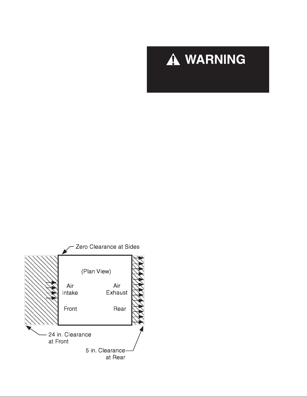
SELF CONTAINED (LOCATION)
Product should always be maintained at proper
temperature. This means that from the time
the product is received, through storage, preparation and display, the temperature of the product must be controlled to maximize the life of the
product.
Be sure to position self contained
merchandisers properly.
SELF CONTAINED models have vented base
panels to allow air circulation through the
condensing unit.
Allow for a minimum 5 in. clearance from
walls, merchandisers, and any other large
objects near the merchandiser’s vented base
panels (for self contained models). Blocking
or restricting air flow will adversely affect performance and may damage the refrigeration
system.
For California Businesses:
This product may contain chemicals known
to the State of California to cause cancer,
birth defects, or other reproductive harm.
This warning is the result of the California State
law known as the California Safe Drinking Water
and Toxic Enforcement Act of 1986, which is
commonly referred to as “Proposition 65.”
This warning does not mean that Hussmann
products will cause cancer or reproductive
harm, or is in violation of any product-safety
standards or requirements. As claried by the
California State government, Proposition 65
can be considered more of a ‘right to know’ law
than a pure product safety law. When used as
designed, Hussmann believes that our products
are not harmful. We provide the Proposition 65
warning to stay in compliance with California
State law. It is your responsibility to provide
accurate Proposition 65 warning labels to your
customers when necessary. For more information
on Proposition 65, please visit the California
State government website.
P/N 2402646_H U.S. & Canada 1-800-922-1919 • Mexico 01 800-890-2900 • www.hussmann.com
Page 9

P/N 2402646_H 1-3
MODEL DESCRIPTION
The MD models are open, vertical, medium
temperature display merchandisers. They are
self contained merchandisers with their own
condensing unit. Each self contained model
has a condensing unit that is factory installed
beneath the display area of the case. The unit
is ready for operation when electrical service is
connected.
Do not store items or ammable materials
atop the unit.
UNLOADING
Unloading from Trailer:
Lever Bar (also known as a Mule, Johnson
Bar, J-bar, Lever Dolly, or Pry Lever)
Move the merchandiser as close as possible to
its permanent location and remove all packaging.
Check for damage before discarding packaging.
Remove all separately packed accessories such
as kits and shelves.
Improper handling may cause damage to the
merchandiser when unloading. To avoid damage:
EXTERIOR LOADING
Do NOT walk on top of merchandisers or
damage to the merchandisers and serious
personal injury could occur.
merchandisers are not structurally
designed to support excessive external
loading such as the weight of a person. Do
not place heavy objects on the merchandiser.
SHIPPING SKID
Each merchandiser is shipped on a skid to
protect the merchandiser’s base, and to make
positioning the case easier.
Remove the top of the crate and detach walls
from each other. Lift crate from the skid.
Unscrew the case from the skid. The fixture
can now be lifted off the crate skid. Lift only at
base of skid! Remove any braces and/or skids
attached (blanket wrapped merchandiser may
have skids).
DO NOT TILT MERCHANDISER ON ITS
SIDE OR END WHEN REMOVING SKID.
Once the skid is removed, the merchandiser
must be lifted —NOT PUSHED— to reposition.
To remove the skid, remove screws attaching
skid to the merchandiser.
1. Do not drag the merchandiser out of the
trailer. Use a Johnson bar (mule).
2. Use a forklift or dolly to remove the
merchandiser from the trailer.
HUSSMANN CORPORATION • BRIDGETON, MO 63044-2483 U.S.A.
Check floor where cases are to be set to see if
it is a level area. Determine the highest part of
the floor.
Do NOT remove shipping crate until the
merchandiser is positioned
for installation.
MD Open Vertical Merchandisers
Page 10
1-4 InstallatIon
MERCHANDISER LEVELING
Be sure to position merchandisers proper-
ly. Level the merchandiser by all four corners.
Merchandiser(s) must be installed level to
ensure proper operation of the refrigeration
system, and to ensure proper drainage of
defrost water.
SERIAL PLATE LOCATION
The serial plate is located at the interior top
left end. It contains all pertinent information
such as model, serial number, amperage rating,
refrigerant type and charge.
Serial Plate
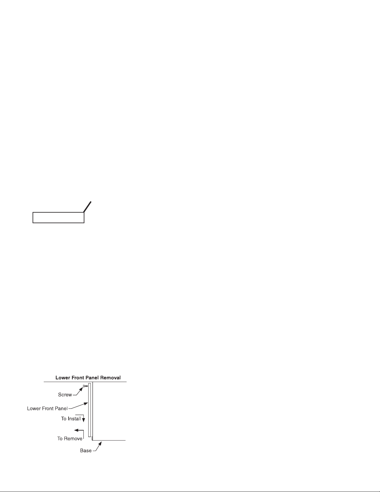
REFRIGERATION UNIT ACCESS
The lower front panel may be removed by
lifting the panel straight upward and over
the tabs on which it is hanging. In a self contained merchandiser, two screws will have to
be removed from either end of the panel. The
panel is installed by reversing the above procedure. Ensure lower front panel is flat against
the floor when installed to prevent air circulation problems on self contained merchandisers.
Lift up and
out to remove
Display
access panel
Be careful not to detach
cable from display when
removing access panel.
Controller (Rear)
SEALING MERCHANDISER TO FLOOR
If required by local sanitary codes, or if the
customer desires, merchandisers may be sealed
to the floor using a vinyl cove base trim. The
size needed will depend on how much variation there is in the floor, from one end of the
merchandiser to the other. Sealing of the lower
front and rear panels on self contained models may hamper their removal for servicing or
maintenance of the condensing unit.
NOTE: Do not allow trim to cover any intake
or discharge grilles located in the lower front
panel.
P/N 2402646_H U.S. & Canada 1-800-922-1919 • Mexico 01 800-890-2900 • www.hussmann.com
Page 11
P/N 2402646_H 2-1
ELECTRICAL / REFRIGERATION
MERCHANDISER ELECTRICAL DATA
Refer to merchandiser serial plate for electrical
information.
FIELD WIRING
Field wiring must be sized for component
amperes stamped on the serial plate. Actual
ampere draw may be less than specified.
To avoid serious injury or death from electrical
shock, always disconnect the electrical power
at the main disconnect when servicing or
replacing any electrical component. This
includes, but is not limited to, such items as
doors, lights, fans, heaters, and thermostats.
— LOCK OUT / TAG OUT —
ALWAYS CHECK THE SERIAL PLATE FOR
COMPONENT AMPERES
ELECTRICAL CONNECTIONS
All wiring must be in compliance with NEC
and local codes. Self contained models are
electrical cord connected at the electrical box.
ELECTRICAL OUTLET:
Before the merchandiser is connected to any
wall circuit, use a voltmeter to check that the
outlet is at 100% of the rated voltage. The wall
circuit must be dedicated for the merchandiser.
Failure to do so voids the warranty. Do not use
an extension cord. Never plug in more than one
merchandiser per electrical circuit.
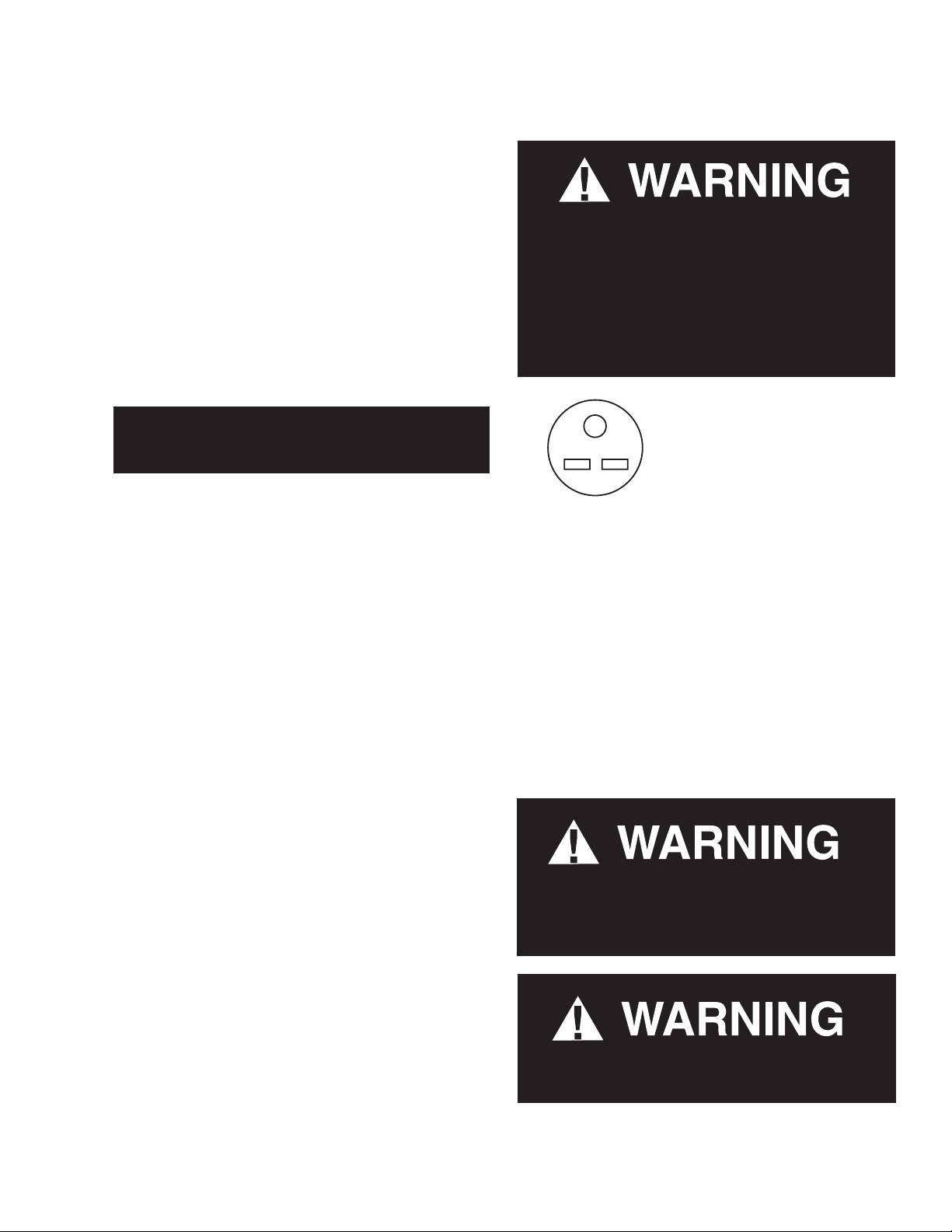
Self-contained models have
factory-installed power cords
attached at the electrical box.
NEMA 6-15P
Receptacle
MD
POWER SWITCH
The main power switch is located in the
electrical box. This switch controls all power
to the case. This switch must be in the OFF
position, and the electrical cord must be
unplugged before starting any cleaning or
service work.
• Always use a dedicated circuit with the
amperage stated on the unit.
• Plug into an outlet designed for the plug.
• Do not overload the circuit
• Do not use long or thin extension cords.
Never use adapters.
• If in doubt, call an electrician.
HUSSMANN CORPORATION • BRIDGETON, MO 63044-2483 U.S.A.
Risk of Electric Shock. If cord or plug becomes
damaged, replace only with a cord and plug of
the same type.
Merchandiser must be grounded.
Do not remove the power supply cord ground.
MD Open Vertical Merchandisers
Page 12
2-2 ElEctrIcal / rEfrIgEratIon
REFRIGERATION
(Self Contained Models)
Each self contained model is equipped
with its own condensing unit and control
panel located beneath the display area. The
correct type of refrigerant will be stamped
on each merchandiser’s serial plate. The
merchandiser refrigeration piping is leak
tested. The unit is charged with refrigerant,
and shipped from the factory with all service
valves open.
Refrigeration lines are under pressure.
Refrigerant must be recovered before
attempting any connection or repair.
WATER OUTLET AND WATER SEAL
The condensate water outlet is located at the
front corners of the evaporator coil area. The
outlet has a factory installed, external water
seal.
For self contained models, this water seal
drains into the condensate evaporator pan
located beneath the merchandiser.
NOTE: All lower base panels must be in place
when the refrigerator is operating. If not,
airflow from the condenser will be directed
over the evaporator pan and defrost water in
the pan may overflow.
When brazing pipes, be sure to use the
insulation blanket shipped with the
merchandiser to prevent damage to the
metal merchandiser bottom.
Product will be degraded and may spoil if
allowed to sit in a non-refrigerated area.
P/N 2402646_H U.S. & Canada 1-800-922-1919 • Mexico 01 800-890-2900 • www.hussmann.com
Page 13

P/N 2402646_H 3-1
START UP / OPERATION MD-10 & MD-14
CONTROLLER OPERATION
The electronic controller is located in the
cassette compartment. The controller comes
factory set, and is ready for use. The front grille
must be removed in order to access this control.
When removing the grille for this operation or
for condenser cleaning, care must be taken not
to damage the display interface cable. It may be
unplugged during this task.
1. Plug the merchandiser plug into its receptacle.
a. The controller display will illuminate.
b. The interior light will illuminate.
2. After the control preprogrammed time
delay of up to 6 minutes, the compressor and
evaporator fan(s) will start if the control is
calling for cooling.
3. The control will cycle the compressor but
may also cycle evaporator fan(s) on and off
determined by the Set-Point and Differential
temperatures.
This cabinet temperature may reect the
refrigeration cycle of the Set-Point and it’s
Differential. The most accurate temperature
on a cabinets operation is to verify the product
temperature.
Taking as an example a VRL case, freezer, If
the Set-Point is -12°F and the Differential is
9°F. (Set-Point) -12°F + 9 (Differential) = -3°F.
The compressor and evaporator fan(s) will cycle
off -12°F and back on at -3°F.
Main Features:
• Panel-mounted
• Energy saving algorithms and optimised
defrost control
• 8 preloaded applications
• Defrost at single / double evaporator
• Frame Heater
• Local network auto-conguration
a. The Set-Point is the adjustable preprogrammed temperature.
b. The Differential is the non-adjustable preprogrammed temperature.
c. The Control is designed to read and
display a cabinet temperature not a product
temperature.
KDEPLUS BUTTONS
The KDEPlus keyboard has 4 keys, as shown in the illustration:
UP
1
DOWN SET
HUSSMANN CORPORATION • BRIDGETON, MO 63044-2483 U.S.A.
2
• Direct load connection (up to 2 HP)
• Supply voltage control LVD
• Presence of an open collector output
STANDBY or ESC
3
4
MD Open Vertical Merchandisers
Page 14

3-2 startup / opEratIon
2 - SPECIFICATIONS
TECHNICAL DATA
Key Functions:
• 2 ON/OFF regulators for HOT/COLD
• Single defrost and double evaporator (heatings,
modulated heaters, reverse cycle, hot gas)
• Evaporator fans and condenser fans
• Frame Heater
• AUX
• Light
• Door switch
• ON /OFF
• Deep cooling cycle
• Day / Night
• Diagnostics
• “Easy Map” programming
• Programmable inputs/outputs
• LINK2 local area network
• RS485 communication protocol: Modbus
• Compatible with Device Manager (DM)
• Compatible with Unicard and Multi-function key
Classification: electronic automatic control (not safety) device for incorporation
Mounting: panel mounting
Type of action: 1.B
Pollution class: 2
Material class: IIIa
Overvoltage category: II
Nominal pulse voltage: 2500V
Temperature: Use: –5 … +55°C - Storage: -30 … +85°C
Power supply: SMPS 100-240Va ±10% 50/60 Hz
Power consumption: 5.5W max
Fire resistance category: D
Software class: A
RTC battery life: In absence of external power, the clock battery will last 3 years.
P/N 2402646_H U.S. & Canada 1-800-922-1919 • Mexico 01 800-890-2900 • www.hussmann.com
Page 15

P/N 2402646_H 3-3
2 - SPECIFICATIONS
TECHNICAL DATA
Classification: electronic automatic control (not safety) device for incorporation
Mounting: panel mounting
Type of action: 1.B
Pollution class: 2
Material class: IIIa
Overvoltage category: II
Nominal pulse voltage: 2500V
Temperature: Use: –5 … +55°C - Storage: -30 … +85°C
Power supply: SMPS 100-240Va ±10% 50/60 Hz
Power consumption: 5.5W max
Fire resistance category: D
Software class: A
RTC battery life: In absence of external power, the clock battery will last 3 years.
: The technical specifications stated in this document regarding measurement (range, accuracy, resolution, etc.) refer to
FURTHER INFORMATION
INPUT CHARACTERISTICS
Measurement range: NTC: -50.0°C ... +110°C; PTC: -55.0°C ... +150°C; PT1000: -60.0°C ... +150°C
(on 3-digit display with +/- sign)
Accuracy: ±1.0° for temperatures below -30°C
±0.5° for temperatures between -30°C and +25°C
±1.0° for temperatures above +25°C
Resolution: 1 or 0.1°C
Buzzer: NO
Analogue/Digital Inputs: 5 configurable NTC/PTC/PT1000/DI inputs
1 multi-function, voltage-free digital input (D.I.)
OUTPUT CHARACTERISTICS
Digital Outputs: OUT1: 1 SPST relay: 2HP
OUT2: 1 SPDT relay: 1HP
OUT3: 1 SPDT relay: 8(4)A
OUT4: 1 SPST relay: 8(4)A
OC (Open Collector) Output: OC: 1 multifunctional output:
max 240V
max 250V
max 250V
max 250V
c 20mA
12V
MECHANICAL CHARACTERISTICS
Dimensions: 121x92 mm
Terminals: faston and screw for wires with cross-section of 2.5mm
Connectors:
Humidity:
TTL for Unicard / Device Manager connection (via DMI)
Usage / Storage: 10...90% RH (non-condensing)
a
a
a
a
2
REGULATIONS
Electromagnetic compatibility: The device complies with Directive 2004/108/EC
Safety: The device complies with Directive 2006/95/EC
Food Safety: The device complies with standard EN13485 as follows:
• Suitable for storage.
• Application: air.
• Climate range A
• measurement class 1 in the range from -25°C to 15°C (*)
(* with Eliwell probes only)
NOTE
the instrument alone and not to any accessories provided, such as the probes.
This means, for example, that the error introduced by the probe must be added to the error of the instrument.
HUSSMANN CORPORATION • BRIDGETON, MO 63044-2483 U.S.A.
MD Open Vertical Merchandisers
Page 16

3-4 startup / opEratIon
CONNECTIONS
TERMINALS
1
2
3
4
5
6
7
8
9
10
11
12
13
14
OUT2 (1HP)
OUT3 (8A)
OUT1 (2HP)
OUT4 (8A)
A
15 16 17
RS485
OPTIONAL
33
32
31
30
29
28
27
26
25
24
23
22
21
20
19
18
12V
OC
D
GND
D
GND
LINK
{
2
GND D
12V
{
KEYB
* N.B.: analogue inputs PB1...PB5 can also be configured as Digital Inputs DI.
TERMINALS
1-2 NEUTRAL.
3 LINE. These are power supply terminals. 19-18 PB1 probe connection.
4 OUT2 Shared Terminal 21-20 PB2 probe connection.
5 N.O. OUT2 23-22 PB3 probe connection.
6 N.C. OUT2 23-24 PB4 probe connection.
7 OUT3 Shared Terminal 23-25 PB5 probe connection.
8 N.C. OUT3 27-26 Digital input (DI).
9 N.O. OUT3 28-29 LINK
10 OUT1 Shared Terminal 30-31 LINK
11 N.O. OUT1 32-33 Open Collector Output (OC).
12 Not Used A TTL Unicard/DMI/Multi Function Key connection
13 OUT4 Shared Terminal 34-35-36 RS485. Connection 1 - Supervision Gateway.
14 N.O. OUT4 37-38-39 RS485. Connection 2 - Supervision Gateway.
These are power supply terminals. 15-16-17
34 35 36 37 38 39
Connection to KDEPlus or KDWPlus external
keyboard or ECPlus echo module.
2
. Connection 1 - local area network.
2
. Connection 2 - local area network.
ELIWELL
ELIWELL
P/N 2402646_H U.S. & Canada 1-800-922-1919 • Mexico 01 800-890-2900 • www.hussmann.com
Page 17

P/N 2402646_H 3-5
LED
RTN400 family controllers will also function even if a keyboard has not been connected.
With KDEPlus or KDWPlus keyboards (which are the same and guarantee the same functions), the display will be as follows:
1
2
3
4
Meaning of LEDs:
No Icon LED Operation Meaning
Permanently on compressor on
1
2
3
Compressor
Defrost
Fans
Blinking Delay, protection or start-up blocked
OFF otherwise
Permanently on Defrost active
Blinking Activated manually or from Digital Input
OFF otherwise
Permanently on Fans active
OFF otherwise
5
6
7
8
Permanently on Energy Saving active
4
5
6
7
8
N.B.: When the instrument is powered on it performs a lamp test, during which time the display and LEDs will
Reduced SET / Economy
Alarm
°F readout
AUX
°C readout
flash for several seconds to check that they all function correctly.
Blinking Reduced setpoint active
OFF otherwise
Permanently on alarm active
Blinking Alarm acknowledged
OFF otherwise
Permanently on °F setting (dro =1)
OFF otherwise
Permanently on Aux output active and/or light on
Blinking Deep cooling on
OFF otherwise
Permanently on °C setting (dro = 0)
OFF otherwise
HUSSMANN CORPORATION • BRIDGETON, MO 63044-2483 U.S.A.
MD Open Vertical Merchandisers
Page 18

3-6 startup / opEratIon
KDEPLUS BUTTONS
The KDEPlus keyboard has 4 keys, as shown in the illustration:
UP
1
DOWN SET
Each key has a different function depending on whether it is:
• Pressed and released
• Pressed for at least 5 seconds
• Pressed and held at start-up
• Pressed in combination with another key.
KEYS
The following table summarizes the function of each key:
No Key
1
2
• Scrolls through menu items
• Decreases values
• Scrolls through menu items
• Decreases values
2
Pressed and released Press for at least 5 secs Start-up
Activates the Manual Defrost function
(from outside menus).
Function can be configured by the user
(from outside menus).
(see parameter H32)
Action
STANDBY or ESC
3
4
---
---
• Returns to the previous menu
3
4
set
level
• Confirms parameter value
• Displays any alarms
(if active)
• Opens Machine Status menu
• Confirms commands
Activates the Stand-by function
(from outside menus).
Opens the Programming Menu
(User and Installer parameters)
---
When pressed during
start-up it enables
the user to select the
application to be loaded.
P/N 2402646_H U.S. & Canada 1-800-922-1919 • Mexico 01 800-890-2900 • www.hussmann.com
Page 19

P/N 2402646_H 3-7
SETPOINT: SETTING AND EDIT LOCK
To display the Setpoint value, press the
set
key to enter the “Machine Status” menu, then press the
set
key again when the “SEt”
label is displayed.
The Setpoint value appears on the display. To change the Setpoint value, press the and keys within 15 seconds.
Press
set
to confirm the modification.
set
set
set
It is possible to disable the keypad on this device.
The keypad can be locked by programming the “LOC” parameter appropriately.
With the keypad locked, you can still access the “Machine Status” menu by pressing
set
to display the Setpoint, but you cannot edit
it. To disable the keypad lock, repeat the locking procedure.
DISPLAY PROBES VALUE
To display the value read by probes connected to the device, press the
set
key and enter the “Machine Status” menu, then press
the key again when one of the probe-related labels “Pb1...Pb5” press the
set
key again. The value measured by the associated
probe will appear on the display.
NOTE: The displayed value is read-only and cannot be modified.
SETPOINT: SETTING AND EDIT LOCK
To display the Setpoint value, press the
label is displayed.
The Setpoint value appears on the display. To change the Setpoint value, press the and keys within 15 seconds.
Press
to confirm the modification.
set
set
set
key to enter the “Machine Status” menu, then press the
set
set
It is possible to disable the keypad on this device.
The keypad can be locked by programming the “LOC” parameter appropriately.
With the keypad locked, you can still access the “Machine Status” menu by pressing
it. To disable the keypad lock, repeat the locking procedure.
set
to display the Setpoint, but you cannot edit
DISPLAY PROBES VALUE
To display the value read by probes connected to the device, press the
the key again when one of the probe-related labels “Pb1...Pb5” press the
probe will appear on the display.
NOTE: The displayed value is read-only and cannot be modified.
KDEPLUS BUTTONS
The KDEPlus keyboard has 4 keys, as shown in the illustration:
set
key and enter the “Machine Status” menu, then press
set
key again. The value measured by the associated
set
key again when the “SEt”
UP
1
DOWN SET
2
KEY-ACTIVATED FUNCTIONS
All models have the UP key set to enable the “Manual Defrost” function.
The DOWN and ESC keys can also be set to activate any other function required by the user.
The parameters for configuring the two keys are:
• H11 = DOWN key configuration
• H33 = ESC key configuration
The values that can be set apply to both keys and the functions that can be activated are:
H32/H33 value Function to enable
0 disabled
1 defrost
2 reduced set
3 Light
4 Energy saving
5 AUX
6 Stand-by
7 Deep cooling cycle
8 Start/end defrost
STANDBY or ESC
3
4
HUSSMANN CORPORATION • BRIDGETON, MO 63044-2483 U.S.A.
MD Open Vertical Merchandisers
Page 20

3-8 startup / opEratIon
MD-10
Evaporator Sensor
Orange
Defrost Termination
Sensor Location
1 23
NEUTRO
NEUTRO
LINE
4
OUT2
56
789
OUT3
10
OUT1
11 12
13
OUT4
14
Orange
Evaporator Sensor
Defrost Termination
Sensor Location
OUT3
OUT1
OUT4
OUT2
MAX.
GND
15 cm.
KEYB
RTN400 SM
TTL
12V
D
RS-485
MODULE
OPTIONAL
12V
GND
GND
33
32
OC
D
D
262728293031
25
222324
21
1 92 0
18
PB2
PB1
SENSOR TE MP
DEF ROST
ORANG E
SENSO R TEMP
GRE EN
AIR
Green
Control
Air Sensor
P/N 2402646_H U.S. & Canada 1-800-922-1919 • Mexico 01 800-890-2900 • www.hussmann.com
Page 21

P/N 2402646_H 3-9
MD-14
4
56
789
10
11 12
13
14
NEUTRO
NEUTRO
LINE
OUT2
OUT3
OUT1
OUT4
OUT3
OUT1
OUT4
OUT2
MAX.
GND
15 cm.
RTN400 SM
TTL
12V
D
RS-485
MODULE
OPTIONAL
12V
GND
GND
33
32
OC
D
D
262728293031
25
222324
21
1 92 0
18
1 23
KEYB
ISOMETRIC
Orange
Evaporator Sensor
Defrost Termination
Sensor Location
PB2
PB1
SENSOR TE MP
DEF ROST
ORANG E
SENSOR TE MP
GRE EN
AIR
9.437
DETAIL B
18.000
DETAIL C
C
B
D
SECTION A-A
DETAIL D
B
AA
SECTION B-B
HUSSMANN CORPORATION • BRIDGETON, MO 63044-2483 U.S.A.
0522934 B
B
MD Open Vertical Merchandisers
Page 22

3-10 startup / opEratIon
1. The controller controls refrigeration
temperature. This is factory installed in the
control panel mounted on the merchandiser’s
fascia. Measure discharge air temperatures at
the center of the louvers.
...ATTENTION
INSTALLER
It is the contractor’s responsibility to
install merchandiser(s) in accordance with
all local building and health codes.
Defrosts are time initiated and temperature
terminated for self contained models. The
defrost setting is factory set as shown above.
— LOCK OUT / TAG OUT —
To avoid serious injury or death from electrical shock, always disconnect the electrical
power at the main disconnect when servicing
or replacing any electrical component. This
includes, but is not limited to, such items as
doors, lights, fans, heaters, and thermostats.
Rear of Controller
P/N 2402646_H U.S. & Canada 1-800-922-1919 • Mexico 01 800-890-2900 • www.hussmann.com
Page 23

P/N 2402646_H 3-11
SHELVES
MD models are equipped with four shelves.
Heights are adjustable in one-inch increments.
Product shelves should be loaded so that the
product does not extend over the front edge
of the shelf. Product loaded over the edge will
interfere with air circulation in the cabinet. It
is also desirable to leave a small space between
the rear interior wall and the product on the
shelves, to allow air to enter the cabinet interior
through the perforations in the rear wall. The
shelves are rated for 130 pounds each load
capacity.
Install the shelf support brackets first to the
desired height before installing each shelf.
Place the rear of the bracket in the desired
slot. Raise the front of the brackets towards
the rear of the cabinet. Once the ends are in
the slot, rotate the bracket forward, locking
it in place. Place the shelf on the bracket. The
shelves are not to be slanted. They must remain
in the horizontal position.
STOCKING
Product should NOT be placed inside the
merchandisers until merchandisers are at
proper operating temperature.
Allow merchandiser 24 hours to operate before
loading product.
Proper rotation of product during stocking is
necessary to prevent product loss. Always
bring the oldest product to the front and set
the newest to the back.
Air dischArge And return flues must
remAin open And free of obstruction At
All times to provide proper refrigeration and
air curtain performance. Do not allow product,
packages, signs, etc. to block these grilles. Do
not use non-approved shelving, baskets,
display racks, or any accessory that could
hamper air curtain performance.
LOAD LIMITS
Each merchandiser has a load limit decal. Shelf
life of perishables will be short if load limit is
violated.
LOAD LIMIT
At no time should merchAndisers be
stocked beyond the loAd limits indicAted.
do not block dischArge Air
louvers.
HUSSMANN CORPORATION • BRIDGETON, MO 63044-2483 U.S.A.
MD Open Vertical Merchandisers
Page 24

3-12 startup / opEratIon
THERMOMETER
The thermometer is located next to the
discharge in the middle of the merchandiser.
The reading is in Cº / Fº.
LIGHTING
Interior lighting is provided by a cool, white
fluorescent bulb. The bulb is sleeved to
maintain proper heat around the bulb for
maximum light intensity and to protect the
product in case of breakage. The bulb can be
replaced without removing shelves or product.
To replace the bulb, twist the bulb and slide
the prongs clear of the lamp holder. Remove
the protective shield from the old bulb, and
put it on the new bulb. Make sure the prongs
on the bulb twist and lock into place when
placing the bulb back in the holders.
NIGHT COVER
All MD models come equipped with a night
cover as a standard feature. The handle for the
cover is located near the lamp, grasp the handle
and pull downward until enough of the cover
has been exposed, allowing the handle to be
placed over the retainer located on the lower
panel. If a night cover must be replaced, follow
these steps: disconnect power to the cabinet.
On the top exterior of the cabinet, there is a
perforated metal cover. Lower the lamp fixture
as if you were replacing the ballast. Lift the left
retainer. Pull the night cover towards you, and
slide to left. Install the new cover in reverse
order.
Optional LED lighting is offered for MD
merchandisers. LEDs are held in place with
clips. The protective light shield is a single
piece.
Product will be degraded and may spoil if
allowed to sit in a non-refrigerated area.
Fluorescent lamps contain mercury vapor.
Mercury exposure at high levels can harm
the brain, heart, kidneys, lungs, and immune
system of people of all ages. Do not break
or puncture fluorescent lamps. Dispose of,
or store, all fluorescent lamps in accordance
with Federal (40 CFR 273), State, and local
hazardous waste requirements. Refer to
http://www.epa.gov/mercury/about.htm
P/N 2402646_H U.S. & Canada 1-800-922-1919 • Mexico 01 800-890-2900 • www.hussmann.com
Page 25

P/N 2402646_H 4-1
MAINTENANCE
CARE AND CLEANING
Long life and satisfactory performance of
any equipment is dependent upon the care it
receives. To ensure long life, proper sanitation
and minimum maintenance costs, these
merchandisers should be thoroughly cleaned,
all debris removed and the interiors washed
down, weekly.
Exterior Surfaces
The exterior surfaces must be cleaned with a
mild detergent and warm water to protect and
maintain their attractive finish.
AbrAsive cleAnsers or scouring pAds.
never use
Interior Surfaces
The interior surfaces may be cleaned with most
domestic detergents, ammonia based cleaners
and sanitizing solutions with no harm to the
surface. Self contained models empty into a
limited capacity evaporation pan, which will
overflow if excess water is used in cleaning.
Do:
•Remove the product and all loose debris to
avoid clogging the waste outlet.
•Store product in a refrigerated area such as a
cooler. Remove only as much product as can
be taken to the cooler in a timely manner.
•Disconnect electrical power before cleaning.
•Thoroughly clean all surfaces with soap and
hot water.
pressure hoses to wAsh the interior.
these will destroy the merchandisers’
sealing causing leaks and poor
performance.
•Take care to minimize direct contact between
fan motors and cleaning or rinse water.
•Do NOT flood merchandiser with water.
never introduce wAter fAster thAn the
wAste outlet cAn remove it.
do not use steAm or high wAter
Do NOT Use:
•Abrasive cleansers and scouring pads, as these
will mar the finish.
•Coarse paper towels on coated glass.
•Ammonia-based cleaners on acrylic parts.
•Solvent, oil or acidic based cleaners on any
interior surfaces.
•Do not use high pressure water hoses.
Product will be degraded and may spoil if allowed to sit
in a non-refrigerated area.
HUSSMANN CORPORATION • BRIDGETON, MO 63044-2483 U.S.A.
Do NOT allow cleaning agent or
cloth to contact food product.
self contAined models empty into A
condensAte evAporAtion pAn thAt will
overflow if too much wAter is introduced
during cleAning.
•Allow merchandisers to dry before resuming
operation.
•After cleaning is completed, turn on power to
the merchandiser.
MD Open Vertical Merchandisers
Page 26

4-2 MaIntEnancE
Do NOT use HOT water on Cold glass Surfaces.
This can cause the glass to shatter and could
result in personal injury. Allow glass fronts, to
warm before applying hot water.
CLEANING UNDER FAN PLENUM
To facilitate cleaning, the fan plenum is hinged.
After cleaning be sure the plenum is properly
lowered into position
result due to improper refrigeration.
or product loss will
CLEANING STAINLESS STEEL SURFACES
Use non-abrasive cleaning materials, and
always polish with grain of the steel. Use warm
water or add a mild detergent to the water and
apply with a cloth. Always wipe rails dry after
wetting.
Use alkaline chlorinated or non-chlorine
containing cleaners such as window cleaners
and mild detergents. Do not use cleaners
containing salts as this may cause pitting and
rusting of the stainless steel finish. Do not use
bleach.
SHUT FANS OFF DURING
CLEANING PROCESS.
DO NOT FLOOD!
Use only enough water necessary to clean
surface. Water must not drip down the case!
Never use ammonia based cleansers, abrasive
cleansers, or scouring pads.
— LOCK OUT / TAG OUT —
To avoid serious injury or death from electrical shock, always disconnect the electrical
power at the main disconnect when servicing
or replacing any electrical component. This
includes, but is not limited to, such items as
doors, lights, fans, heaters, and thermostats.
P/N 2402646_H U.S. & Canada 1-800-922-1919 • Mexico 01 800-890-2900 • www.hussmann.com
Page 27

P/N 2402646_H 4-3
CLEANING COILS
Condenser coils should be cleaned at least once
per month. Additional cleaning may be needed
depending on the operational environment. A
dirty condenser blocks normal airflow through
the coils.
Airflow blockage increases energy consumption
and reduces the merchandiser’s ability to
maintain operating temperature.
To clean the coils, use a vacuum cleaner with
a wand attachment and a soft (non-metallic)
brush to remove dirt and debris. Do not bend
coil fins. Always wear gloves and protective
eye wear when cleaning near sharp coil fins
and dust particles.
HUSSMANN CORPORATION • BRIDGETON, MO 63044-2483 U.S.A.
MD Open Vertical Merchandisers
Page 28

4-4 MaIntEnancE
4-4 MaIntEnancE
CLEANING EVAPORATION PAN
(SELF CONTAINED ONLY)
The condensate water outlet for self
contained models empties into a limited
capacity evaporation pan.
Debris or dirt accumulation inside the condensate
evaporation pan or on the heater coil will
reduce the pan’s evaporation capacity and
cause premature heater failure. The evaporation
pan waste water will overflow and spill onto the
floor if the heater is not properly operating.
Remove accumulated debris from the
evaporation pan. Wipe down heater coil with a
cloth and warm water. Be sure to remove any
dirt, debris or liquids from the heater coil.
Evaporation Pan is Hot!
and poses risk of bodily injury – Always Wear gloves
and protective eye wear when servicing. Turn off
evaporation pan heater, and allow pan to cool.
Water introduced during cleaning will cause
the evaporation pan to overflow.
REMOVING SCRATCHES FROM
BUMPER
Most scratches and dings can be removed
using the following procedure.
1. Use steel wool to smooth out the surface
area of the bumper.
2. Clean area.
3. Apply vinyl or car wax and polish surface
for a smooth glossy finish.
P/N 2402646_H U.S. & Canada 1-800-922-1919 • Mexico 01 800-890-2900 • www.hussmann.com
P/N 2402646_G U.S. & Canada 1-800-922-1919 • Mexico 1-800-890-2900 • www.hussmann.com
Page 29

P/N 2402646_H 5-1
SERVICE
REPLACING FAN MOTORS AND
BLADES
Should it ever be necessary to service or
replace the fan motors or blades be certain
that the fan blades are reinstalled correctly.
the blAdes must be instAlled with rAised
embossing (pArt number on plAstic
blAdes) positioned As indicAted on the
pArts list.
For access to these fans:
1. Remove product and place in a refrigerated
area. Turn off power to the merchandiser.
2. Remove bottom display pans.
3. Disconnect fan from wiring harness.
4. Remove fan blade.
To avoid serious injury or death from electrical shock, always disconnect the electrical
power at the main disconnect when servicing
or replacing any electrical component. This
includes, but is not limited to, such items as
doors, lights, fans, heaters, and thermostats.
11. Close air gaps under fan plenum. Warmer
air moving into refrigerated air reduces
effective cooling. If the plenum does not
rest against the case bottom without gaps,
apply foam tape to the bottom of the fan
plenum to reduce improper air movement.
Use silicone sealant to close other gaps.
— LOCK OUT / TAG OUT —
5. Lift fan plenum and remove screws
holding bottom of motor to fan basket.
6. Replace fan motor and blade.
7. Lower fan plenum.
8. Reconnect fan to wiring harness.
9. Turn on power.
10. Verify that motor is working and blade is
turning in the correct direction.
12. Reinstall display pans. Bring merchandiser
to operating temperature before restocking.
Product will be degraded and may spoil if
allowed to sit in a non-refrigerated area.
HUSSMANN CORPORATION • BRIDGETON, MO 63044-2483 U.S.A.
Note: Plenum length
and number of fans will
vary with model.
MD Open Vertical Merchandisers
Page 30

5-2 sErvIcE
REPLACING ELECTRONIC BALLASTS /
LED POWER SUPPLIES
MD Merchandisers may be equipped with
fluorescent or LED lights. Fluorescent lights
are powered by electronic ballasts. LED lights
are powered by power supplies. The procedure
to replace these parts is similar.
Canopy Ballast or Power Supply
The canopy ballast or power supply is located
in the electrical box on top of the MD case.
To gain access:
1. disconnect the electricAl power to the
merchAndiser.
2. Remove screws attaching the raceway cover,
then remove cover.
3. Service or replace ballast/power supply
as required. Reassemble items as they were
originally installed.
4. Reconnect the electrical power.
REPLACING FLUORESCENT LAMPS
Fluorescent lamps have a plastic shield. When
the lamp is replaced, keep the lamp shield to
install over the new lamp.
The switch under the display lamp cover
operates the display lamp.
REPLACING LED FIXTURES
The switch under the display lamp cover
operates the display lamp. For LEDs, this
protective shield is incorporated as part of the
LED fixture. Rotate the LED fixture to release
it from the lamp harness.
Fluorescent lamps contain mercury vapor.
— LOCK OUT / TAG OUT —
To avoid serious injury or death from electrical shock, always disconnect the electrical
power at the main disconnect when servicing
or replacing any electrical component. This
includes, but is not limited to, such items as
doors, lights, fans, heaters, and thermostats.
Remove Plastic Pins Attaching Display Lamp
Mercury exposure at high levels can harm
the brain, heart, kidneys, lungs, and immune
system of people of all ages. Do not break
or puncture fluorescent lamps. Dispose of,
or store, all fluorescent lamps in accordance
with Federal (40 CFR 273), State, and local
hazardous waste requirements. Refer to
http://www.epa.gov/mercury/about.htm
P/N 2402646_H U.S. & Canada 1-800-922-1919 • Mexico 01 800-890-2900 • www.hussmann.com
Page 31

P/N 2402646_H A-1
appEndIx a — tEchnIcal data
Models
MD-10UL MD-14UL
Standard Parts
Descripon Part Number
LH End (Beige) less glass 130721 X X
RH End (Beige) less glass 130722 X X
LH End (Black) less glass 0530442 X X
RH End (Black) less glass 0530443 X X
Plexi glass end insert 1006104 X X
Clip end glass (Beige) 0522940 X X
Clip end glass (Black) 0530681 X X
Front Bumper (RED) 37.75” 1006227 X
Front Bumper (RED) 51.5” 1006223 X
Evaporator Fan Motor (Motor 12W,basket,less blade) 0461804000 X
Evaporator Fan Motor (Motor 5W,basket& blade) 0505079 X
Evaporator Fan Blade 0142780002 X
Evap Fan Harness 0523592 X
Evap Fan Harness 1804163 X
Sensor NTC 4 mts Green 3023554 X X
Sensor NTC 4 mts Orange 3031571 X X
Control Eliwell RTN400 3023537 X X
Control Display KDE 3023552 X X
Display cable 5 meter 3023553 X X
Condensate pan heater relay SPDT NC 208V 0342599002 X X
Compressor Relay (T92P7A22-240) 1804241 X X
Power Switch 03S422 X X
Thermometer (horizontal) 1700559000 X X
Front Plexiglass 0520750 X
Front Plexiglass 0520751 X
Night Curtain 35S0841 X
Night Curtain 35S0842 X
Honeycomb 0520740 X
Honeycomb 0520500 X
Power Cord NEMA 6-15P 0508528 X X
Flourscent light (Canopy) F18T8 06S149 X
Flourscent light (Canopy) F032/841 32W 1803337 X
Ballast 06S187 X X
Lamp Holder 06S188 X X
Safety Sleeve 06S07417 X
Safety Sleeve 06S07414 X
Light Switch 1801241000 X X
LED Light 3’ 0515963 X
LED light 4’ 0515965 X
LED Power Supply 0518898 X X
LED lamp Holders 1803376 X X
Light Clips (LED) 0518906 X X
HUSSMANN CORPORATION • BRIDGETON, MO 63044-2483 U.S.A.
MD Open Vertical Merchandisers
Page 32

A-2 appEndIx a — tEchnIcal data
Models
Refrigeraon
Condensing Unit Assy (134a) Complete w/ condensate pan 0521330 X
Compressor (NJ6226Z) 208/230/60 2000555 X X
Condensing Unit Assy (134a) Complete w/ condensate pan 0521156
Condenser Coil E108812001 X
Condenser Coil E108814001
Drier (C052-S) 1700481000 X X
Condenser Fan Motor 21S071 X
Condenser Fan Blade 0500354 X X
Condenser Fan Motor 0521460
Assembly Evaporator Coil (Complete) 130421000 X
Assembly Evaporator Coil (Complete) 130422000
Evaporator coil E108813001 X
Evaporator coil E108815001
Models
Condensate Pan
Electric Condensate Pan Assy (w/heater & oat switch) 1H11037001 X X
Condensate Pan Heater (750w) 1H07734 X X
Float Switch 1804342 X X
MD-10UL MD-14UL
MD-10UL MD-14UL
X
X
X
X
X
Models
Sheel Metal Replacement Parts Painted
Front Access Panel 0539989 X
Front Access Panel 0539990
LH End Panel -Base 0539537 X X
RH End Panel -Base 0539538 X X
Rear Base Panel- not to be painted 0210158 X
Rear Base Panel- not to be painted 0210159
Shelf Assembly (includes shelf,brackets and PTM) 130761 X
Shelf Assembly (includes shelf,brackets and PTM) 130762
Shelf Bracket 13062 X X
Shelf 130451 X
Shelf 130452
PTM 30S8151 X
PTM 30S8152
Boom Back Shelf 130221 X
Boom Back Shelf 130222
Boom Front Shelf 0210214 X
Boom Front Shelf 0210215
All these part numbers are painted assemblies
MD-10UL MD-14UL
X
X
X
X
X
X
X
P/N 2402646_H U.S. & Canada 1-800-922-1919 • Mexico 01 800-890-2900 • www.hussmann.com
Page 33

P/N 2402646_H A-3
MD — Plan View
Dimensions shown as inches and (mm).
8 3/8
(213)
4 1/4
(108)
REFRIGERATION
OUTLET
ELECTRICAL
OUTLET
17 1/8
(435)
7 3/4
(197)
4 (102) 3 7/8 (98)
DRAIN
Front of Merchandiser
Model Length
MD-10 39"
MD-14 52"
HUSSMANN CORPORATION • BRIDGETON, MO 63044-2483 U.S.A.
L
MD Open Vertical Merchandisers
Page 34

A-4 appEndIx a — tEchnIcal data
MD — Cross Section
REFRIGERATION DATA
Note: This data is based on store temperature
and humidity that does not exceed 75°F and
55% R.H. unless otherwise stated. Schedule
defrost at night while lights are off.
MD
Condensing Unit (hp)
MD-10 1
MD-14 1
Condensing Unit
Capacity
MD-10 7376
MD-14 7376
(Btu/hr at std. rating conditions)
DEFROST DATA
Frequency (hr)
Offtime
Failsafe (minutes) 10
Defrost Termination 50°F
Temperature
Refrigerant Charge
MD-10 (R134a) 22.928 oz 0.65 kg
MD-14 (R134a) 36.261 oz 1.028 kg
1
PHYSICAL DATA
P/N 2402646_H U.S. & Canada 1-800-922-1919 • Mexico 01 800-890-2900 • www.hussmann.com
Page 35

P/N 2402646_H A-5
Electrical Data
Note: These are rated values for individual components and should not be added together to
determine total merchandiser electrical load.
MD-14 MD-10
Number of Fans – 5W 2 1
Amperes Watts Amperes Watts
Evaporator Fans
208-230V 60Hz Standard 0.6 10 0.7 12
Condensate Pan Heaters (230V) 3.6 750 3.6 750
Condensing Unit (208/230V, 1Ph, 60Hz) Standard
MD-10 MD-14
Compressor LRA 41 41
Compressor RLA 9.5 9.5
Product Data
MD-10
AHRI Total Display Area
1
(Sq Ft/Case) 11.7 ft
2
/case ( 3.57 m
2
MD-14
AHRI Total Display Area
1
(Sq Ft/Case) 15.79 ft
2
/case ( 4.81 m
2
1 Computed using AHRI 1200 standard methodology:
Total Display Area, ft2 [m2] / Unit of Length, ft [m]
/case)
/case)
HUSSMANN CORPORATION • BRIDGETON, MO 63044-2483 U.S.A.
MD Open Vertical Merchandisers
Page 36

A-6 appEndIx a — tEchnIcal data
ELECTRIC SPECS
MD-10
MODEL MD10UL
VOLTAGE 208-230 V
FRECUENCY 60 HZ
COMPRESSOR NJ6226Z EMBRACO
D
OC
12V
RTN400 SM
LINE
NEUTRO
NEUTRO
OUT2
123456
BK
BK
W
SENSOR T EMP
DEFRO ST
D
GND
GND
OUT2
OUT3
OUT3
7 8 9 10 11 12 13
BK
ORANGE
BK
RS-485
OUT1
MODULE
TTL
PB2
21222324252627282930313233
OPTIONAL
OUT1
BK
12V
GND
OUT4
1920
D
14
SENSOR T EMP
AIR
GREEN
PB1
18
15 cm.
MAX.
OUT4
KEYB
W
W
ELECTRIC BOX
W
RE LAY
BK
WARNING
UNPLUG THE EQUIPMENT BEFORE TO MAKE ANY
REPARATION TO AVOID ANY DAMAGE
ADVERTENCIA:
DESCONECTAR EL EQUIPO ANTES DE HACER
CUALQUIER REPARACIÓN, PARA EVITAR ALGUN DAÑO.
W
1
LA MP
2
5
3
4
OPTIONAL KIT
BL
BL
W
C
S
R
BK
BK
CO NDENSE R
W
648
1
0
2
FAN
SHE LF LED
SHE LF LED
SHE LF LED
EVAPORATOR
FAN
SHE LF LED
BK
R
BALLAST
W
SWIT CH
S1
R
S2
BALLAST
2
14
COMPRESOR
W
LEVEL
SWIT C H
RE LAY
T STAT
LIMIT
CO NDENSE R
HEATER
BK
S3
MAIN
SWIT C H
BK
S1
S2S4
R
BK
NE MA
6-15 P
230 V
60HZ
W
0521458_F
1HP
P/N 2402646_H U.S. & Canada 1-800-922-1919 • Mexico 01 800-890-2900 • www.hussmann.com
Page 37

P/N 2402646_H A-7
ELECTRIC SPECS
MD-14
MODEL MD14UL
VOLTAGE 208-230 V
FRECUENCY 60 HZ
COMPRESSOR NJ6226Z EMBRACO
D
OC
12V
RTN400 SM
LINE
NEUTRO
NEUTRO
OUT2
123456
BK
W
BK
W
SENSOR T EMP
DEFRO ST
D
GND
GND
OUT2
OUT3
OUT3
7 8 9 10 11 1213
BK
ORANGE
BK
RS-485
OUT1
MODULE
TTL
PB2
21222324252627282930313233
OUT1
BK
SENSOR T EMP
AIR
GREEN
PB1
18
1920
OPTIONAL
12V
GND
OUT4
14
D
OUT4
15 cm.
MAX.
KEYB
W
RE LAY
WARNING
UNPLUG THE EQUIPMENT BEFORE TO MAKE ANY
REPARATION TO AVOID ANY DAMAGE
ADVERTENCIA:
DESCONECTAR EL EQUIPO ANTES DE HACER
CUALQUIER REPARACIÓN, PARA EVITAR ALGUN DAÑO.
W
1
W
C
S
R
BK
BK
CO NDENSE R
W
648
1
0
2
FAN
EVAPORATOR
FAN
BK
2
5
3
4
2
14
COMPRESOR
ELECTRIC BOX
W
LEVEL
SWIT C H
W
RE LAY
W
T STAT
LIMIT
CO NDENSE R
HEATER
BK
BK
S3
MAIN
SWIT C H
W
LA MP
SWIT CH
S1
BK
S1
S2S4
R
S2
BALLAST
W
BL
0521458_E
R
230 V
60HZ
1HP
BK
NE MA
6-15 P
HUSSMANN CORPORATION • BRIDGETON, MO 63044-2483 U.S.A.
MD Open Vertical Merchandisers
Page 38

To obtain warranty information
or other support, contact your
Hussmann representative.
Please include the model and
serial number of the product.
Hussmann Corporation, Corporate Headquarters: Bridgeton, Missouri, U.S.A. 63044-2483 01 October 2012
 Loading...