

Page 1
2402646
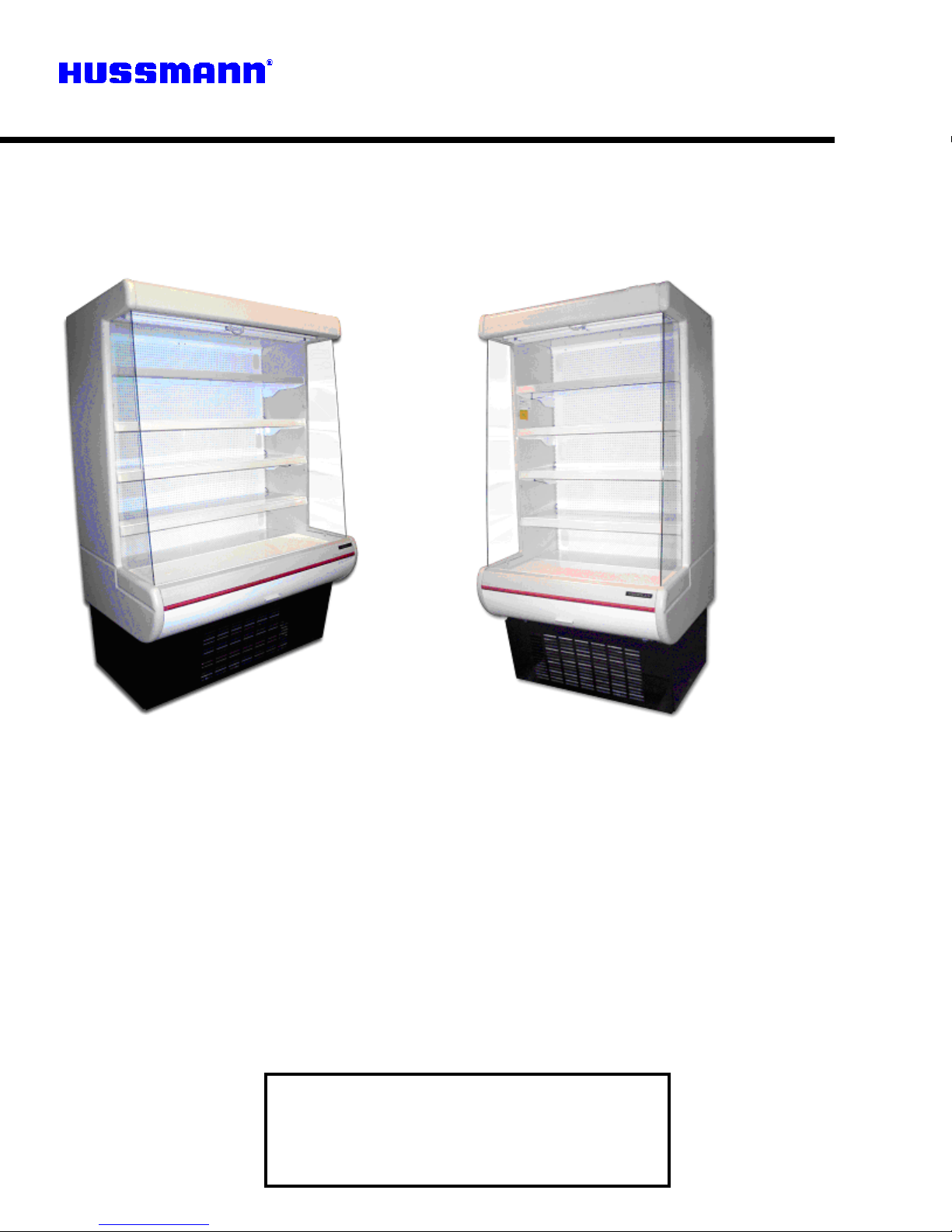
SERIES MD’s
Medium Temperature
Merchandisers
PLEASE READ THIS MANUAL BEFORE USING THE PRODUCT
Installation &
Operation Manual
P/N 2402646A
MD-10, MD-14
Agust 2005
HUSSMANN - CORPORATION
1331 Seamist Drive
Houston TX 77008
Phone (713) 861-9171
Page 2

2402646
TABLE OF CONTENTS PAGE
INTRODUCTION, INSPECTION, LOCATION and CLEARANCE
SKID, LEVELING and SEALING
DRAINS
SERIAL PLATE
AIR DISTRIBUTION and PRODUCT LOADING
POWER REQUIREMENTS
ELECTRICAL BOX, POWER SWITCH, TIME CLOCK
CONNECTIONS
SPECIFICATIONS, DIMENSIONS, BTU CAPACITY
SHELVING, TEMPERATURE CONTROL,
CONDENSING UNIT
THERMOMETER
LIGHTING, LAMP SWITCH, BALLAST
NIGHT COVER, CLEANING EXTERIOR
3
3
3
3
3
3
4
4
4
4
5
5
5
5
CLEANING INTERIOR
REFRIGERATION
LEAK TESTING AND EVACUATION
TROUBLE SHOOTING CHARTS
LIGHTING TROUBLESHOOTING
5
6
6
7
8
REPLACEMENT PARTS INFORMATION 8
WARRANTY. 9
2
Page 3

2402646
INTRODUCTION, INSPECTION, LOCA TION and
CLEARANCE SKID, LEVELING and SEALING and
DRAINS
Hussmann MD model cabinets offer maximum
versatility in the display of medium temperature
prechillded products such as prepared salads,
pizzas, fresh entrees, and dairy products.
INSPECTION
-
Upon receipt of the cabinet, carefully inspect the
crating and equipment for damage. If damage is found,
note on the delivery receipt where and how extensive
the damage before signing.
After removal of the crating, again inspect
the cabinet
for damage. If damage is found, contact the delivering
carrier and request for an inspection and inspection
report be made for the purpose of filing a claim. Save
as much as the crating as possible and move the
cabinet as little as possible until after the inspection.
Once the cabinet has been installed and properly
leveled,
it
should be sealed to the floor as shown in the
following drawing, utilizing a NSF approved material
such as General Electric RTV -102 silicone sealant or
equivalent.
DRAINS
-
Remote draining is not required on self -contained
models. The condensate water from the evaporator
drains out through the bottom of the cabinet, through a
hose trap located to the underside of the condensing
unit area, into an electrically heated condensate pan.
Until the trap gets filled with water; there may be a small
frost accumulation in the evaporator coil area. This frost
should disappear after the trap gets filled with water;
usually after the first defrost. The drains for the
condensate water are located in the front corners of the
evaporator coil area. These drains must be kept clear to
ensure proper drainage of the condensate water.
THIS IS YOUR RESPONSABILITY
LOCATION and CLEARANCE
-
It is very important that careful consideration be given to
the cabinet location in the store where direct sunlight
would shine into the cabinet, and locations where drafts
from air conditioning, open doors, and fans would blow
directly into the cabinet should be avoided.
The MD cabinets have front air intake and rear air
discharge for proper airflow over the condensing unit. A
minimum distance of two feet must be left open in front
of the cabinet so that air intake to the condensing unit is
not obstructed.
In addition, a minimum of five inches clearance behind
the case and eighteen inches above the case is
required to allow for proper discharge air flowing over
the condensing unit.
SKID-
The shipping skid should be left on the cabinet until it is
near its selected location in the store. The skid provides
protection for both the cabinet and floor. The skid can be
removed by backing out the screws that are run through
the front and rear base rails into the skid. Once these
screws are removed, the cabinet may be slid carefully
off the skid.
LEVELING
-
The cabinet must be properly leveled to ensure full
drainage of the water produced during the off and
defrost cycles. Level the cabinet from front to rear and
end-to-end.
SEALING
-
SERIAL PLATE-
The serial plate is located on the interior left hand end. It
contains all pertinent information such as model, cabinet
serial number, refrigerant type and amount etc. The
information on this plate is very helpful when servicing or
ordering replacement parts. This plate should never be
altered or removed for any reason
AIR DISTRIBUTION and PRODUCT LOADING
This cabinet has a forced-air circulation system. Air flows
through the perforations in the back wall over the
product on the shelves, as well as out the baffles located
above the product, across the face of the product and
into the return air grill.
WHEN LOADING THE PRODUCT DO NOT
PLACE IT SO THAT IT EXTENDS OVER THE
SHELF EDGES OR OVER THE RETURN AIR
GRILL. IT IS ALSO IMPORTANT NOT TO
PLACE THE PRODUCT TIGHT AGAINST THE
BACK PANEL. THIS WILL RESTRICT AIR
FROM FLOWING OUT OF THE
PERFORATIONS AND OVER THE PRODUCT.
POWER REQUIREMENTS
-
The MD-10 and MD-14 Comes equipped with a 15A
power cord, Under no circumstances should the
grounding prong on the cords be removed.
It is very important for the safety of both you and your
customer to have each circuit properly grounded. A
qualified electrician should perform all wiring in
accordance with the National Electrical Code and/or all
3
Page 4

2402646
local codes. Separate circuits are recommended for
MODEL Length Width Height
each cabinet in order to prevent product loss due circuit
overloading of malfunction of other equipment, which
may be on the same circuit. For proper operation of the
equipment, voltage measured at the compressor must
not vary more that 5 % from the cabinet serial plate
rating.
If either high or low voltage condition exists, contact your
electrician or local power company. If service or
maintenance is being performed on the cabinet, make
MD-10 39" 33" 5/8 77"
MD-14 52" 33" 5/8 77"
ELECTRICAL
MODEL Refrg. Run Fuse
MD-10 R-134A 10.3 15
25.50oz.
sure the power supply to the cabinet is off before
proceeding.
MD-14 R-134A 9.5 15
30.25 oz.
ELECTRICAL BOX
-
The electrical box is located behind the front access
MODEL BTU/HR EVAP COND AMB
BTU CAPACITY
panel. Access to this box is gained by removing this
panel.
The box contains the power switch and contactor.
Power to the cabinet should be disconnected before any
service is performed on this box.
MD-10 4635 20 130 75-80
MD-14
6430
20
130
75-80
SHELVING-
The MD models come equipped with four shelves. They
POWER SWITCH
are adjustable on one inch increments. When loading
the shelves with product, they should be loaded so that
The main power switch is located in the electrical box.
This switch controls all power to the case. This switch
must be in the off position before starting any cleaning or
service work on the equipment.
CONNECTIONS
-
Check all electrical and refrigeration connections
thoroughly for tightness. Make sure the refrigeration
tubing is not rubbing or chafing against itself or other
components. Electrical connections should be tight.
Condenser fan motor blades should spin freely without
hitting anything. Install all protective covers, start the
cabinet and allow to pull down to temperature before
loading.
SPECIFICA TIONS - DIMENSIONS
the product does not extend over the front edge of the
shelf. Product loaded over the edge will interfere with air
circulation in the cabinet. It is also desirable to leave a
small space between the rear interior wall and the
product on the shelves to allow air to enter the cabinet
interior through the perforations in the rear wall.
The shelves are rated for 130 pounds each load
capacity. When installing the shelves, first install the
shelf support bracket at the sired height. Place the rear
of the bracket in the desired slot. Raise the front of the
bracket towards the rear of the cabinet. Once the ends
are in the slot, rotate the bracket forward locking it in
place. Place the shelf on the bracket. Load the product.
The shelves are not to be slanted. They must remain in
a horizontal position.
TEMPERATURE CONTROL
-
4
Page 5

2402646
Safe Net
bulb located under the top header. The bulb is sleeved
to maintain proper heat around the bulb for maximum
light intensity and to protect the product in case of
breakage. The bulb can be replaced without removing
shelves or product .To replace the bulb, twist the bulb
and slide the prongs clear of the lamp holder. Remove
the shield from the old bulb and put it on the new bulb.
When placing the bulb back in the holders, make sure
the prongs on the bulb twist and lock into place.
LAMP WITCH -
The lamp switch is located on the right hand end of the
upper header near the lamp. This switch controls the
lamp only. Before replacing a bulb or ballast, make sure
power to the cabinet is disconnected.
BALLAST -
The ballast is located on the top interior of the cabinet
near the center of the cabinet. Access to the ballast is
gained by removing the two screws, (one on each end)
of the lamp fixture. Rotate the fixture down towards the
bottom of the cabinet.
CONDENSING UNIT-
A regular program should be established for cleaning
the fin and tube condenser. Normally this cleaning is
required every 1-2 months, but individual store
conditions may dictate otherwise. A clean condenser
increases cabinet efficiency and extends compressor
life.
NIGHT COVER-
All MD models come equipped with a night cover as a
standard feature .The handle for the cover is located
near the lamp, grasp the handle and pull downward until
enough of the cover has been exposed allowing the
handle to be placed over the retainer located on the
lower panel. In the event a night cover has to be
replaced, follow these steps: disconnect power to the
cabinet. On the top exterior of the cabinet, there is a
perforated metal cover. Remove the cover. Lower the
lamp fixture as if you were replacing the ballast. Lift the
left retainer Pull the night cover toward you and slid to
left. Install the new cover in reverse order. Torn power
back on.
Access to the condenser is gained by removing the
front access panel. Power should be disconnected to
the cabinet before removing this panel. Slide the
condensing unit forward. Clean the surface of the fins
with a vacuum or soft brush. Do not use hard or sharp
objects as damage to the fins and tubing may occur.
Compressed air maybe used. However, proper safety
precautions should be observed. After cleaning,
carefully push the condensing unit back in making slure
not to kink or pinch any tubing or wires. Also make sure
the tubing and wires are not rubbing on any other
components. Make sure all drain hoses are back in the
proper places before replacing front access cover.
THERMOMETER –
The thermometer reading is in C°/ F°, is located next to
discharge in the middle of the case
LIGHTING -
Interior lighting is provided by a cool white fluorescent
CLEANING EXTERIOR When cleaning the exterior of the cabinet, use a soft
cloth or sponge with water and a mild detergent. Do
not use any thing abrasive, as this will mar the finish.
Clean the glass with a glass cleaner of your choice.
CLEANING INTERIOR-
Disconned fue power and remove all product. Allow the
cabinet to warm to room temperature. Remove the front
access panel and monitor the amount of water going
into the condensate pan. It may be necessary to
remove some water so the pan does not overflow. Use
soft cloth or sponge with a mild detergent to clean the
interior. Check the drain to ensure no debris has
become lodged in it during cleaning. Make sure the
drain hose(s) are into the condensate pan, set timer for
correct time of day, install removed covers. Wipe
interior dry and restart cabinet. Allow cabinet to achieve
5
Page 6

2402646
proper operating temperature before reloading product.
REFRIGERATION -
The MD models employ a refrigeration system using a
hermetic compressor, with refrigerant flow being
controlled through the use of a capillary tube. In the
event the capillary tube may become partially or fully
restricted, replace the entire tube. Do not attempt to cut
and/or splice the tube. Capillary tube sizes are:
MD-10 .064 I.D. x 115 inches.
MD-14 .076 I.D. x 118.50 inches.
LEAK TESTING-
The test gas cylinder must be equipped with a pressure
gauge and regulator so that system test pressures do
not exceed maximum allowable limits. Do not ever use
anything other than a R-22/Nitrogen mixture for leak
testing.
Attach a refrigerant test gas cylinder to your service
manifold and connect the manifold to the charging port
on the liquid line valve.
Charge an R-22/Nitrogen mixture into the system,
raising the pressure to the unit's nameplate for the low
side and high side pressures. Using an electronic
detector, carefully check the entire system for leaks.
Take special care to inspect all brazed and flare
connections.
EVACUATION –
After the system is proven leak tight, thoroughly
evacuate the system according to the following
procedure:
Discharge the refrigerant-nitrogen mixture, allowing it to
blow from the system as rapidly as possible, into any
empty cylinder. Be sure that all service valves are open
to allow all of the mixture to be discharged.
Connect a deep-drain vacuum pump to both the high
and low side of the system. Pull a vacuum on the
system to at least 1500 microns.
Break the vacuum by adding refrigerant into the system
until the pressure is above 0 psig. Always charge the
refrigerant line into the system through a new drier in the
charging manifold line. A 16 cubic inch drier is sufficient
for this purpose.
Repeat steps 2 and 3 two more times, the third time
evacuating the system to 500 microns.
6
Page 7

2402646
TROUBLE SHOOTING CHARTS
TROUBLE
PROBABLE CAUSE SOLUTION
Compressor will not start no
noise
Compressor will not start, cuts
out on overload
Warm storage temperature
1. Power disconnected 1. Check service cord or
2. Blown fuse or breaker 2. Replace fuse or reset
3. Defective or broken wiring 3. Repair or replace
4. Defective overload 4. Replace
5. Defective temperature
control
1. Low voltage 1. Check voltages at cabinet,
2. Defective compressor 2. Replace
3. Defective relay 3. Replace
4. Restriction (pinched cap
tube)
5. Restriction (moisture) 5. Leak check, replace drier
6. Condenser blocked with
dust and dirt
7. Defective condenser fan
motor
wiring connection.
breaker
5. Replace
should not be more than 5%
below rating.
4. Repair or replace
evacuate and recharge
6. Clean condenser
7. Replace
Compressor runs
continuously. Product too
warm
Compressor runs
continuously. Product too cold
1. Short of refrigerant 1. Leak check, replace drier
evacuate and recharge
2. Cabinet location too warm 2. Move to cooler location or
correct excessive heat source.
3. Refrigerant overcharge 3. Purge system, evacuate and
recharge.
4. Low voltage, compressor
cycling on overload
1. Short of refrigerant 1. Leak check, replace drier,
2. Inefficient compressor 2. Replace
1. Defective control 1. Replace
2. Short on refrigerant 2. Leak check, replace drier,
4. Check voltage at
compressor should not be
more than 5% below rating
evacuate and recharge
evacuate and recharge.
7
Page 8

2402646
TROUBLE SHOOTING LIGHT CHART
PROBLEM SOLUTION
Lights won’t start 1. Check light switch
2. Check continuity to ballast
3. Check to see if bulbs inserted properly in
sockets
4. Check voltage
Lights flicker 1. Allow lamps to warm up
2. Check lamp sleeve for cracks
3. Check sockets for moisture and proper contact
4. Bulb replacement may be necessary
5. Check voltage
6. New bulbs tend to flicker until used
Ballast Hums 1. Check voltage
REPLACEMENT PARTS INFORMATION
2. Replace ballast
IMPORTANT - Please read carefully to assure prompt and accurate service.
ORDERING PARTS REPLACEMENT-
Contact your nearest Hussmann Distributor.
Always specify model and serial number of cabinet.
If correct part number is not know, give a clear description of part itself and its function in the cabinet or remote
unit
Same as first three items in Ordering Replacement Parts Procedure.
Give original installation date of cabinet and, if possible, forward a copy of the original invoice or delivery receipt.
All shipments of in warranty replacement parts will be invoiced from the factory until such time as the defective
part is returned and proved to be defective by our Quality Control Department.
Contact your Hussmann Distributor for instructions on returning in-warranty parts.
Warranty parts must be returned to the factory within 30 days of date of failure to assure proper disposition.
Lack of any of the above information may result in the shipment of the wrong part, or a relay in shipment.
8
Page 9

2402646
SERIES MD’S
LIMITED WARRANTY
This warranty is made to the original purchaser-user and is NOT TRANSFERABLE.
WARRANTIES:
FIRST YEAR:
Hussmann Corporation warrants new Hussmann equipment and all parts there of to be free from defects in material and workmanship at the time of
purchase.
Hussmann's obligation under this warranty shall be limited to repairing or exchanging, at its option, any part or parts, without change F.O.B. factory or nearest authorized
parts depot, which may prove defective within one year from date of original installation (not to exceed fifteen (15) months from date of shipment from the factory), and which
is proven to the satisfaction of Hussmann to be thus defective.
ADITIONAL FOUR YEARS:
Hussmann agrees to repair or replace at its option, Hussmann equipment determined through its inspection to have an inherent foam insulation failure
or refrigerant leak within such insulation area for period of live (5) years from date of factory shipment. In addition, Hussmann agrees to repair or
exchange, at its option, the original Motor Compressor Unit only with a compressor of like or of similar design and capacity if it is shown to the
satisfaction of Hussmann that the Motor Compressor is inoperative due defects in factory workmanship or material under normal use and service as
outlined in Hussmann's "Installation Instructions" which are shipped inside new Hussmann equipment. Hussmann's sole obligation under this warranty
shall be limited to a period not to exceed five (5) years from date of factory shipment. The term "Motor Compressor Unit" does not include electric
controls; such as relays, capacitors, pressure controls, or fan motor assembly, condenser, receiver, etc. The warranty does not include any equipment
to which the Motor Compressor Unit is connected such as cooling coils, temperature controls, refrigerant metering devices, etc.
The warranties to repair or replace above recited, are the only warranties, expressed, implied, or statutory, made by Hussmann with respect to
Hussmann equipment. Hussmann makes no express or implied warranties as to merchantability or fitness for a particular purpose or use.
Hussmann neither assumes, not authorizes any person to assume for it, any other obligation or liability on connection with the sale of said equipment or
any part thereof.
EXCLUSIONS_
1. There is NO warranty against breakage of glass.
2. THIS WARRANTY SHALL NOT APPLY TO LOSS OF FOOD OR CONTENTS OF THIS EQUIPMENT DUE TO FAILURE FOR ANY REASON. 3.
Hussmann Corporation SHALL NOT BE LIABLE:
A) For any repairs or replacements made by buyer without the written consent of Hussmann or when equipment is installed or operated in a manner contrary to the printed
instructions covering installation and service which accompanied.
B) For any damage, delays, or losses, direct or consequential, caused by defects, nor for damage caused by shortages or reduced supply of material, fire, flood, strikes, acts
of God, or circumstances beyond its control.
C) When the failure or defect of the equipment or of any part or parts is incident to ordinary wear, accident (including accident occurring in transit), abuse or misuse; or when
the serial number of the equipment has been removed, defaced, altered, or tampered with.
D) When this equipment is operated on low or improper voltage, or is put to a use other than normally recommended by Hussmann, such as remoting self-contained
equipment.
E) Toward payment of any removal or installation charges of warranted parts and equipment or for transportation charges in connection therewith.
December,1997.
Hussmann Corporation
HUSSMANN-CORPORATION
1331 Seamist Drive
Houston TX 77008
Phone (713)861-9171
9
 Loading...