

Page 1
B
D
C
E
D
A
E
HUSSMANN CORPORATION, Bridgeton, MO 63044-2483 U.S.A.
P/N 0378417C
®
Note: Changed items have been underlined.
Item Part # Description Wiring Item #
F
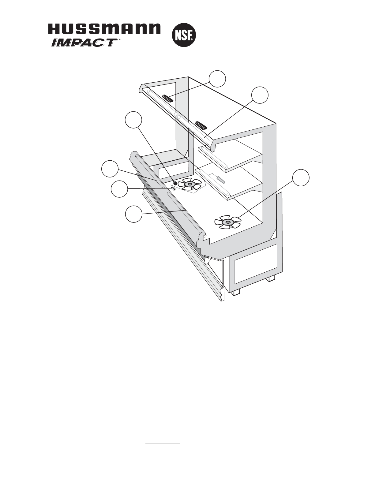
AN ASSEMBLIES AND THERMOSTATS
A. 9W Fan Assembly (1)
0047000 Fan Motor, Evaporator
0315470 Fan Blade
embossing toward motor
B. 0411744 Standard Non-adjustable (2)
Defrost Thermostat
C. 0137880 Optional Adjustable (3)
Refrigeration Thermostat
Item Part # Description Wiring Item #
L
AMPS AND BALLASTS
D. 0428648 Ballast, Electronic
2 lamps (4)
D. 0428649 Ballast, Electronic
3 lamps (4)
E. Fluorescent Lamp (5)
Replace with like fixtures
M3
Data Sheet Set
P/N 0378417C
NSF
®
Certified
June 2004
Merchandisers
Page 2
8 ft 12 ft
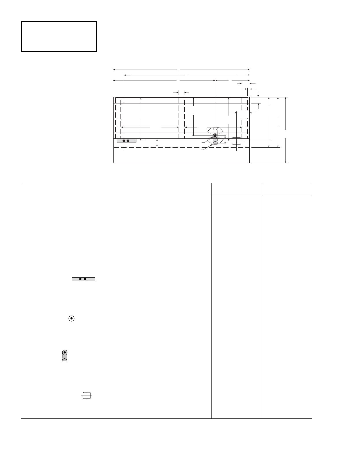
General
(A) Case Length (without ends or partitions) 96
3
/8 (2448) 144 1/2 (3670)
Maximum outside dimension of case back to front
(includes bumper) 46
1
/
2 (1180) 46
1
/
2 (1180)
Back of case to front of splash guard 35
1
/
4 (897) 35
1
/
4 (897)
Back of case to outside edge of front skid rail 29
1
/
2 (747) 29
1
/
2 (747)
Width of skid rail 4
1
/
2 (114) 4
1
/
2 (114)
Right hand end of case to inside edge of external support 5 1/2 (140) 5 1/2 (140)
Distance between edges of external support and center support 40
5
/8 (1032) 40 5/8 (1032)
Distance between edges of center supports NA 44 (1118)
Stub-up area between front skid rail and splash guard 4 (102) 4 (102)
Electrical Service (Electrical Field Wiring connection point)
(B) Right hand end of case to center of farthest knockout 88
3
/8 (2245) 136 1/2 (3467)
Back outside of case to center of knockout 30
1
/2 (775) 30 1/2 (775)
Length of electrical raceway 34
1
/2 (778) 34 1/2 (778)
Waste Outlet
(C) Left hand end of case to the center of waste outlet 72
1
/
4 (1835) 72
1
/
4 (1835)
(D) Right hand end of case to the center of waste outlet 24
1
/8 (613) 72 1/4 (1835)
Back outside of case to center of waste outlet 27
1
/2 (699) 27 1/2 (699)
Water Seal
Edge of water seal to center of waste outlet 4 (102) 4 (102)
Outside diameter of the drip pipe 1
1
/2 (38) 1 1/2 (38)
*Note: Water seal outlet must clear front skid rail.
Refrigeration Outlet
Back of case to center of refrigeration outlet 30
5
/8 (778) 30 5/8 (778)
Right-hand end of case to center of refrigeration outlet 9 (230) 9 (230)
2 of 7
Engineering
Dimensions shown as inches and (mm).
M3 Data Sheet
HUSSMANN CORPORATION, Bridgeton, MO 63044-2483 U.S.A.
Meat and Produce
09-2003
A
B
C
Electrical
30
(775)
1
/2
5
/8
40
(1032)
4 (102)
1
4
/8 (105)
1
27
/2
(699)
(1032)
Waste Outlet
Water Seal
(See Note*)
Front
40
5
/8
D
5
/8
30
(778)
4 (102)
Refrigeration
9
(230)
4
5
3
1
1
/2 (114)
1
/2 (140)
/8 (35)
29 1/2
(749)
35
(891)
1
/8
1
46
/4
1174)
(
Page 3
3 of 7
P/N 0378417C
HUSSMANN CORPORATION, Bridgeton, MO 63044-2483 U.S.A.
C
O
I
L
FAN
38 1/8
(969)
7
1
/2
(152)
4
(102)
30 3/8
(773)
3
1
/8
(079)
6 5/8 (171)
4
1
/
2
(114)
4 (102)
39 3/8
(1001)
42 1/2
(1079)
73 7/8
(1877)
40 3/4
(1035)
16 3/4
(425)
27
1
/2 (699)
29 1/2 (749)
35
1
/4 (897)
46
1
/2 (1180)
30 3/8
(771)
25 5/8
(650)
17 3/8
(441)
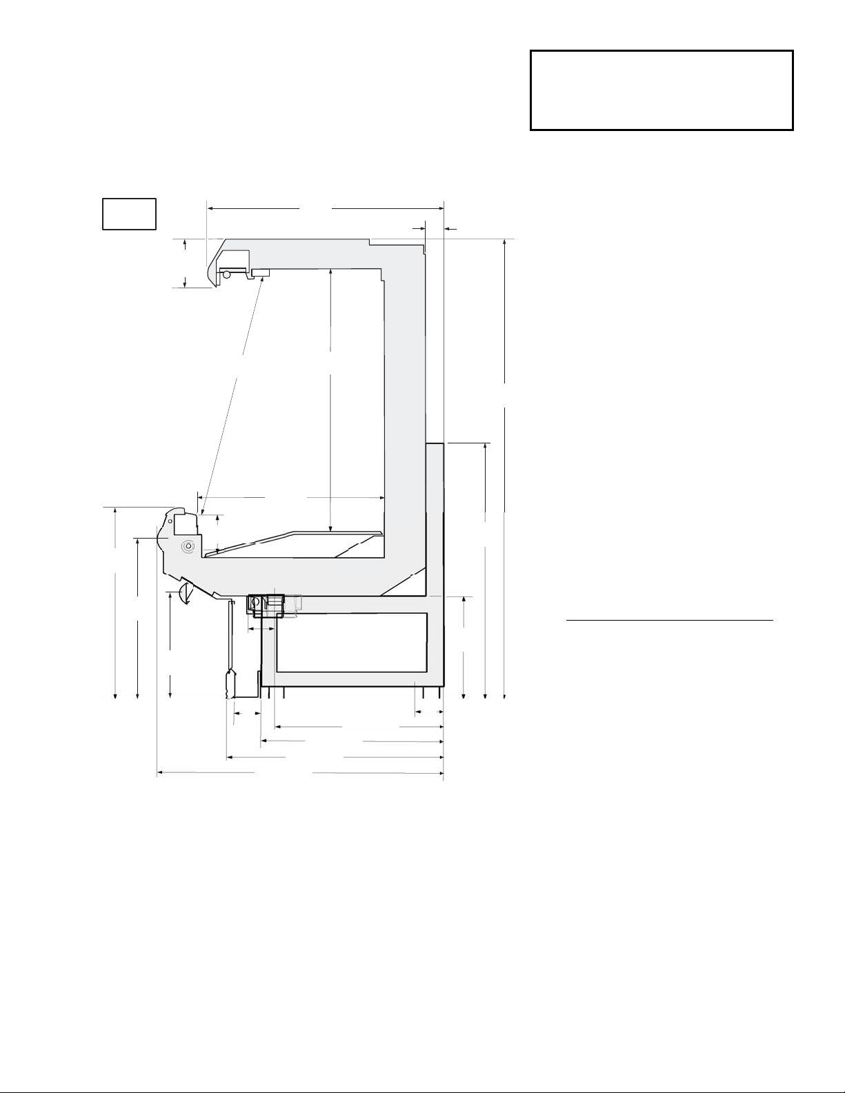
M3
Dimensions shown as inches and (mm).
Multi-deck, 3 Display Levels
NSF Certification
These merchandisers are manufactured to meet ANSI /National
Sanitation Foundation (NSF®) Standard #7 requirements.
Impact M3
Meat, Delicatessen
Pre-cut and Packaged Produce
REFRIGERATION DATA
Note: This data is based on store temperature
and humidity that does not exceed 75°F and
55% R.H.
M3 M3E
Discharge Air (°F) 28 28
Evaporator (°F) 18 21
Unit Sizing (°F) 16 19
Btu/hr/ft* M3 M3E
Parallel 1120 1055
Conventional 1205 1155
*For all refrigeration equipment other than
Hussmann, use conventional Btu values.
DEFROST DATA
M3 M3E
Frequency (hr) 66
Defrost Water (lb/ft/day) 77
(± 15% based on case configuration and
product loading).
OFFTIME M3 M3E
Temp Term (°F) 48°F48°F
Failsafe (minutes) 30 35
E
LECTRIC OR G
AS
Not Recommended
Standard Defrost Thermostat
Close on rise: close 48°F — open 33°F
CONVENTIONAL CONTROLS
Low Pressure Backup Control
M3 M3E
CI/CO** 12°F / 2°F 14°F / 4° F
Indoor Unit Only, Pressure Defrost
Termination** 48°F
**Use a Temperature Pressure Chart to
determine PSIG conversions.
PHYSICAL DATA
Merchandiser Drip Pipe (in.) 1 1/
2
Merchandiser Liquid Line (in.)
3
/8
Merchandiser Suction Line (in.)
7
/8
Estimated Charge (lb)*** M3 M3E
8 ft 2.3 2.7
12 ft 3.3 3.9
***This is an average for all refrigerant types.
Actual refrigerant charge may vary by
approximately half a pound.
Length (in.) added to Lineup by Each
End or Insulated Partition 1
1
/2
Page 4

Electrical Data
8 ft 12 ft
Number of Fans – 9W 2 3
Amperes Watts
Merchandiser 8 ft 12 ft 8 ft 12 ft
Fans (Refrigeration)
Standard (120V 60Hz) 1.40 2.10 105 160
Energy Efficient (120V 60Hz) 0.76 1.14 50 75
Export (230V 50Hz) 0.76 1.14 114 171
Cycling Anti-sweat Heaters NA NA NA NA
Minimum Circuit Ampacity
With Standard Fans (120V 60Hz) 1.60 2.30
With Energy Efficient Fans (120V 60Hz) 0.96 1.34
With Export Fans (230V 50Hz) 0.96 1.34
Maximum Over Current Protection 120V 20 20
Maximum Over Current Protection 230V 15 15
Standard Lighting 8 ft 12 ft 8 ft 12 ft
1 Row Canopy 0.51 0.77 59 85
Optional Lighting
1 Row Canopy and 1 Row Rail 1.02 1.54 118 170
2 Row Canopy 1.02 1.54 118 170
2 Row Canopy and 1 Row Rail 1.53 2.31 177 255
Optional Shelf Lighting
1 Row of Shelves 0.51 0.77 59 85
2 Rows of Shelves 1.02 1.54 118 170
4 of 7 M3 Data Sheet
HUSSMANN CORPORATION, Bridgeton, MO 63044-2483 U.S.A.
Impact M3
Meat and Delicatessen
Precut and Packaged Produce
Page 5

5 of 7P/N 0378417C
HUSSMANN CORPORATION, Bridgeton, MO 63044-2483 U.S.A.
2 & 3 Fans
120V POWER
ROWN BAND
B
Fans
Fan Wiring
Offtime Defrost
120V NEUTRAL
B
1
ROWN BAND
Optional Shelf Harness and Light Circuits for
One Row of Shelves
Shelf Harness
Connector
W
B
120 V
Power
Connector
G
B
W
4
BL
R
BL
BL
Shelf Light Circuits
W
G
G
G
R
BL
Connector
Connector
G
BL
Defrost
Termination
Thermostat
Dark Blue
2
Refrigeration
Thermostat
Light Blue
3
To
Condensing
Unit
}
Shelf Lighting
B
G
BL
R
R
5
Connector
G
BL
R
BL G
R
Connector
Connector
G G
BL
R
5
BL
G
R
BL
Connector
Connector
R
5
WARNING
All components must have mechanical ground, and the merchandiser must be grounded.
CIRCLED NUMBERS = PARTS LIST ITEM NUMBERS
Grayed components in 12 foot models only.
R = Red Y = Yellow G = Green BL = Blue B = Black W = White
= 120V POWER = 120V NEUTRAL = Field GROUND
= Case GROUND
Page 6

6 of 7 M3 Data Sheet
HUSSMANN CORPORATION, Bridgeton, MO 63044-2483 U.S.A.
Light Circuits
Lighting 1 Row Canopy (Standard on Multideck)
120V NEUTRAL
ORANGE OR TAN BAND
120V POWER
ORANGE OR TAN
BAND
Light
Switch
W
B
Optional Lighting 2 Row Canopy
120V NEUTRAL
ORANGE OR TAN BAND
120V POWER
ORANGE OR TAN
BAND
Light
Switch
W
B
W
B
4
R
BL
4
BL
4
BL
BL
R
R
BL
BL
BL
R
BL
R
BL
R
R
5
R
5
R
5
Optional Lighting 1 Row Rail
120V NEUTRAL
ORANGE OR TAN BAND
120V POWER
All components must have mechanical ground, and the merchandiser must be grounded.
ORANGE OR TAN
BAND
Light
Switch
B
W
4
R
BL
BL
BL
R
WARNING
CIRCLED NUMBERS = PARTS LIST ITEM NUMBERS
Grayed components in 12 foot models only.
R = Red Y = Yellow G = Green BL = Blue B = Black W = White
= 120V P
OWER = 120V NEUTRAL
R
5
Page 7

7 of 7P/N 0378417C
HUSSMANN CORPORATION, Bridgeton, MO 63044-2483 U.S.A.
18 in.
0°
16 in.
0°
The shelf configuration of this merchandiser is critical!
2-Shelf Configuration for M3 & M3E
Top shelf must be 16 inches wide and
placed at a 0° angle.
Second shelf may be either 16 or 18 inches
wide and it must be positioned at a 0° angle.
These shelf positions apply to all product applications.
 Loading...