

Page 1
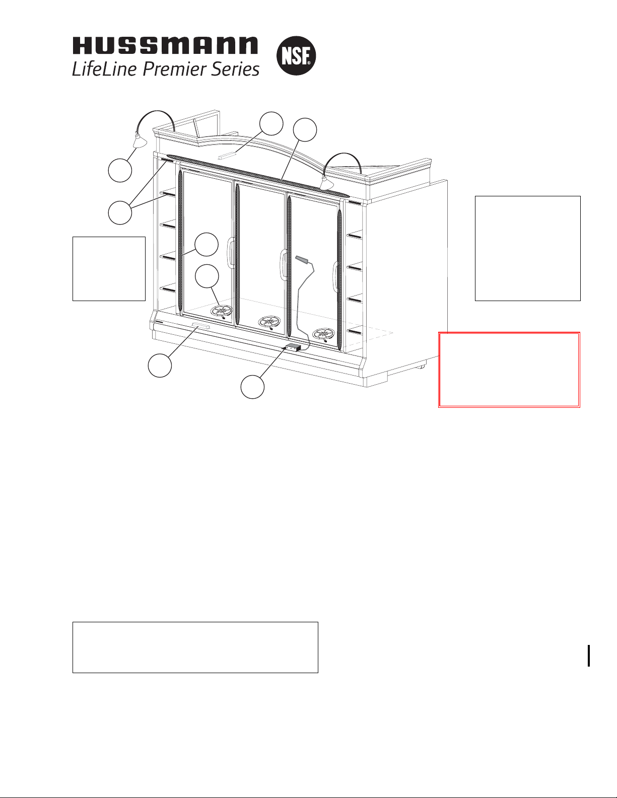
Item Part # Description Wiring Item #
FAN ASSEMBLIES, AND THERMOSTATS
A. 12W Standard Fan Assembly (1)
MO.4410103 Fan Motor, Evaporator
FB.4780446 Fan Blade
12W Optional Energy Efficient Fan Assembly (1)
MO.4410546 Fan Motor, Evaporator
FB.4780446 Fan Blade
B. Optional Adjustable Refrigeration Thermostat (2)
Item Part # Description Wiring Item #
LED FIXTURES AND POWER SUPPLY
C. EP.4481861 Power Supply (3)
D. Door Lamp, LED
BU.4440875 3500K Center (4)
BU.4440877 4100K Center (4)
BU.4440876 3500K End (5)
BU.4440878 4100K End (5)
E. Facade Lamp, LED (6)
BU.4441411 2900K 29.5 In. Length
BU.4441412 2900K 30.5 In. Length
F. BU.4441413 Gooseneck Lamp (7)
G. BU.4441414 Dry Goods Lamp, LED 3500K (8)
(NOTE: Gooseneck Lamp and Dry Goods Lamp
cannot be applied to same merchandiser.)
SH.4991645 KLU9600
Dry Goods Shelf, Lighted, Pearwood
F
B
C
E
A
D
C
G
LifeLine Premier
RMN
with
INNOVATOR
Doors
Technical Data Sheet
P/N 0510311_B
NSF
®
Certified
May 2010
We reserve the right to change
or revise specifications and
product design in connection
with any feature of our
products. Such changes
do not entitle the buyer to
corresponding changes,
improvements, additions or
replacements for equipment
previously sold or shipped.
OPTIONS SHOWN:
• Lighted Facades
• Facade Arch
• Gooseneck Lamps
• Dry Goods Storage
• Bump Out Partitions
Warning:
Terminal block NOT for
case-to-case
wire connection!
P/N0510311B
©2010 HUSSMANN CORPORATION • BRIDGETON, MO 63044-2483 U.S.A.
U.S. & CANADA 1-800-922-1919 • MEXICO 1-800-522-1900 • WWW.HUSSMANN.COM
Refer to I
NNOVATOR REACH-IN GLASS DOOR
I
NSTALLATION AND SERVICE
manual, P/N 0425683,
for Innovator and Innovator II door and frame
replacement parts.
NOTE: Revision B adds Btu note on page 5, updates stocking level on page 4, updates item numbers on pages 8-11, and updates pages
1, 2, 3, 5-8, 10 & 11. Changes are underlined, circled or marked with a vertical line in the margin.
®
Page 2
LifeLine Premier
RMN with Innovator Doors
Technical Data Sheet
2 of 11
U.S. & Canada 1-800-922-1919 • Mexico 1-800-522-1900
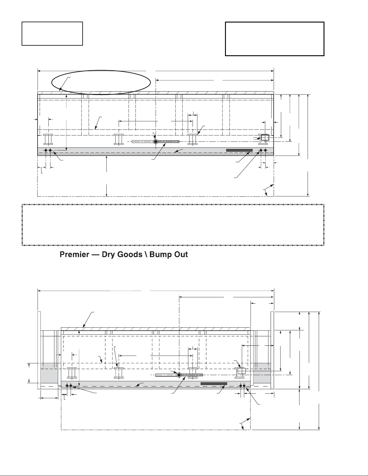
Reach-In
2, 3, 4 & 5 Door
Engineering
Plan Views
PHYSICAL DATA
Merchandiser Drip Pipe (in.) 1 1/4
Merchandiser Liquid Line (in.)
3
/8
Merchandiser Suction Line (in.)
7
/8
LifeLine Premier
RLN - RMN
Plan View
05-2010
Base narrow footprint 5-door merchandiser is shown above, without Bump Out, Dry Goods, Partitions or Ends.
Illustrated below is a 4-door merchandiser with Dry Goods cabinets and Bump Out end partitions.
Refer to chart on Page 3 for detailed dimensional information on options.
Dimensions shown as inches and (mm).
Dimensions shown as inches and (mm).
4 in. (102 mm ) Required Air Gap
from Merchandiser Insulated Panel
to Wall or Flat Surface
A
C
7
(178)
(102)
6
(152)
Bottom
Front
Support
37
(956)
5
/8
Skid/
External
Base
48
(1219)
Waste Outlet
Refrigeration Outlet
Electrical Wireway
(see note *)
13/4
(44)
4
26
(673)
1
/2
Water Seal
(see note **)
Front
5-Door Shown
Splashguard
Relay & Terminal
Block Location
(see note *)
13/4
(44)
Door Swing
Clearance
D
B
28
(711)
30
(778)
5
/8
39
(1010)
3
/4
66
(1683)
1
/4
LifeLine
Narrow Footprint Plan View
2, 3 & 4 Door
12 7/8
(327)
10 3/4
(273)
Shelf
Area
A
4 in. (102 mm ) Minimum Air Gap
from Merchandiser Insulated Panel
to Wall or Flat Surface
7
(178)
37 5/8
(956)
External
Skid/
Base
Bottom
Front
Support
Electrical Wireway
3
4
(102)
1
(44)
/4
(see note *)
48
(1219)
Waste Outlet
Splashguard
Water Seal
(see note **)
Front
4-Door Shown
6
(152)
Refrigeration
Relay & Terminal
Block Location
C
Outlet
1 3/4
(44)
Door Swing
Clearance
1
15
/4
(387)
12
(305)
28
39 3/4
(711)
D
Shelf
(1010)
30 5/8
(778)
3
51
(1314)
/4
Area
B
(see note *)
26
from Bumper
1
(674)
78
(1988)
/2
1
/4
Page 3
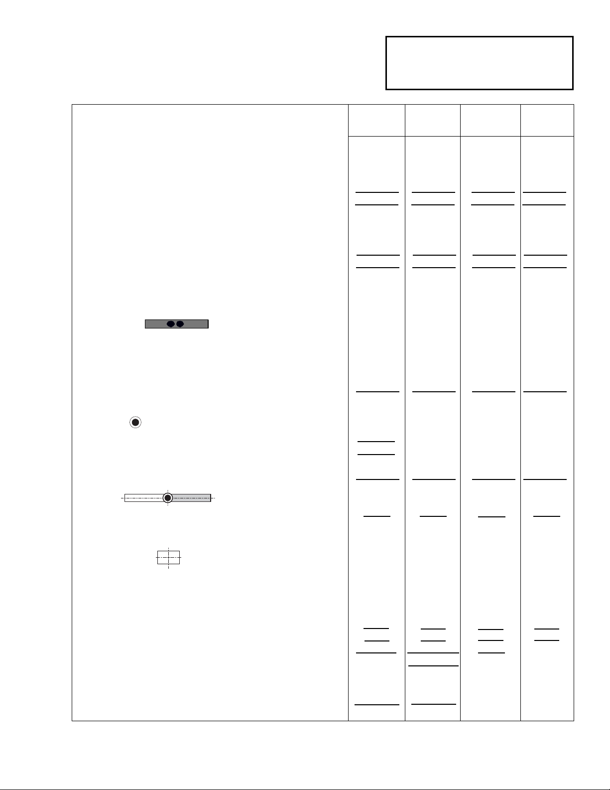
3 of 11P/N 0510311_B
HUSSMANN CORPORATION • BRIDGETON, MO 63044-2483 U.S.A. • WWW.HUSSMANN.COM
LifeLine Premier
RMN
With INNOVATOR Doors
Medium Temperature
Plan View Dimensions for
LifeLine Premier
Options
Abbreviations: DG = Dry Goods section BO = Bump Out
2 Dr 3 Dr 4 Dr 5 Dr
General
(A) Merchandiser Length 62 (1575) 92
1
/
2 (2350) 122
7
/
8 (3121) 153
3
/
8 (3896)
(A) Merchandiser Length BO includes 2 bump-out ends 66 (1676) 96
1
/
2 (2451) 126
7
/
8 (3222) 157
3
/
8 (3997)
(A) Merchandiser Length DG includes 4 ends and dry goods cabinets 92
1
/
2 (2350) 123 (3124) 153
3
/
8 (3896) NA
Maximum O/S dimension of merchandiser back to front *** 39
3
/
4 (1010) 39
3
/
4 (1010) 39
3
/
4 (1010) 39
3
/
4 (1010)
Maximum O/S dimension of merchandiser back to front BO *** 51
3
/
4 (1314) 51
3
/
4 (1314) 51
3
/
4 (1314) 51
3
/
4 (1314)
***
Includes bumper. Add 26 1/
2 in. (673 mm) for door swing.
Interior width of dry goods cabinet 10 3/
4 (273) 10
3
/
4 (273) 10
3
/
4 (273) NA
Interior depth of dry goods cabinet 12
7
/
8 (327) 12
7
/
8 (327) 12
7
/
8 (327) NA
Back of merchandiser to rear of splashguard 35
7
/
8 (911) 35
7
/
8 (911) 35
7
/
8 (911) 35
7
/
8 (911)
Back of merchandiser to rear of splashguard BO 47
7
/8 (1216) 47 7/8 (1216) 47 7/8 (1216) 47 7/8 (1216)
Width of Skid rail 3 3/4 (95) 3 3/4 (95) 3 3/4 (95) 3 3/4 (95)
Width of Bottom Front Support 6 (152) 6 (152) 6 (152) 6 (152)
Stub-up area between front support and splashguard 3 1/
8 (79) 3
1
/
8 (79) 3
1
/
8 (79) 3
1
/
8 (79)
Electrical Service
(B) RH end of merchandiser to the center of nearest knockout 4 (102) 4 (102) 4 (102) 4 (102)
(B) RH end of merchandiser to the center of nearest knockout BO 6 (152) 6 (152) 6 (152) 6 (152)
(B) RH end of merchandiser to the center of nearest knockout DG 19
1
/4 (489) 19 1/4 (489) 19 1/4 (489) NA
RH end of merchandiser to the center of LH knockout 58 (1473) 88 1/
2 (2248) 118
7
/
8 (3019) 149
3
/
8 (3794)
Back O/S of merchandiser with bump-out to center of knockout 49
5
/8 (1260) 49 5/8 (1260) 49 5/8 (1260) 49 5/8 (1260)
* NOTE: Electrical Field Wiring Connection Point is at terminal.
Waste Outlet
(C) Right end of merchandiser to center of waste outlet 23 7/
8 (606) 54
1
/
4 (1378) 46
1
/
4 (1175) 76
5
/
8 (1946)
(C) Right end of merchandiser to center of waste outlet BO 25
7
/8 (657) 56 1/4 (1429) 48 1/4 (1226) 78 5/8 (1997)
(C) Right end of merchandiser to center of waste outlet DG 39 (991) 69 1/2 (1765) 61 1/2 (1562) NA
Back O/S of merchandiser with bump-out to center of waste outlet 42 5/
8 (1083) 42
5
/
8 (1083) 42
5
/
8 (1083) 42
5
/
8 (1083)
Water Seal
Edge of water seal to center of waste outlet 13 (330) 13 (330) 13(330) 13 (330)
Schedule 40 PVC drip pipe 1
1
/
4 (32) 1
1
/
4 (32) 1
1
/
4 (32) 1
1
/
4 (32)
** NOTE: Field installed water seal outlets, tees, and connectors are shipped with merchandiser.
Refrigeration Outlet
(D) RH end of merchandiser to center of RH refrigeration outlet 5 3/8 (136) 5 3/8 (136) 5 3/8 (136) 5 3/8 (136)
(D) RH end of merchandiser to center of RH refrigeration outlet BO 7 3/8 (187) 7 3/8 (187) 7 3/8 (187) 7 3/8 (187)
(D) RH end of merchandiser to center of RH refrigeration outlet DG 20 5/
8 (524) 20
5
/
8 (524) 20
5
/
8 (524) NA
Back O/S of merchandiser with bump-out to center of refrigeration outlet 44 (1118) 44 (1118) 44 (1118) 44 (1118)
Outside bottom front supports from end of merchandiser 7 (178) 7 (178) 7 (178) 7 (178)
Outside bottom front supports from end of merchandiser BO 9 (229) 9 (229) 9 (229) 9 (229)
Outside bottom front supports from end of merchandiser DG 26
1
/
2 (673) 26
3
/
4 (679) RH 24 (610) 24 (610)
37
1
/2 (952) LH
Center bottom front support from Centerline 24 (610) 24 (610) 24 (610) 24 (610)
Center bottom front support from Centerline BO 24 (610) 24 (610) 24 (610) 24 (610)
Center bottom front support from Centerline DG 6 3/4 (171) LH 8 3/4 (222) RH 24 (610) NA
Distance between Center and Outside supports will vary
Page 4
LifeLine Premier
RMN with Innovator Doors
Technical Data Sheet
4 of 11
U.S. & Canada 1-800-922-1919 • Mexico 1-800-522-1900
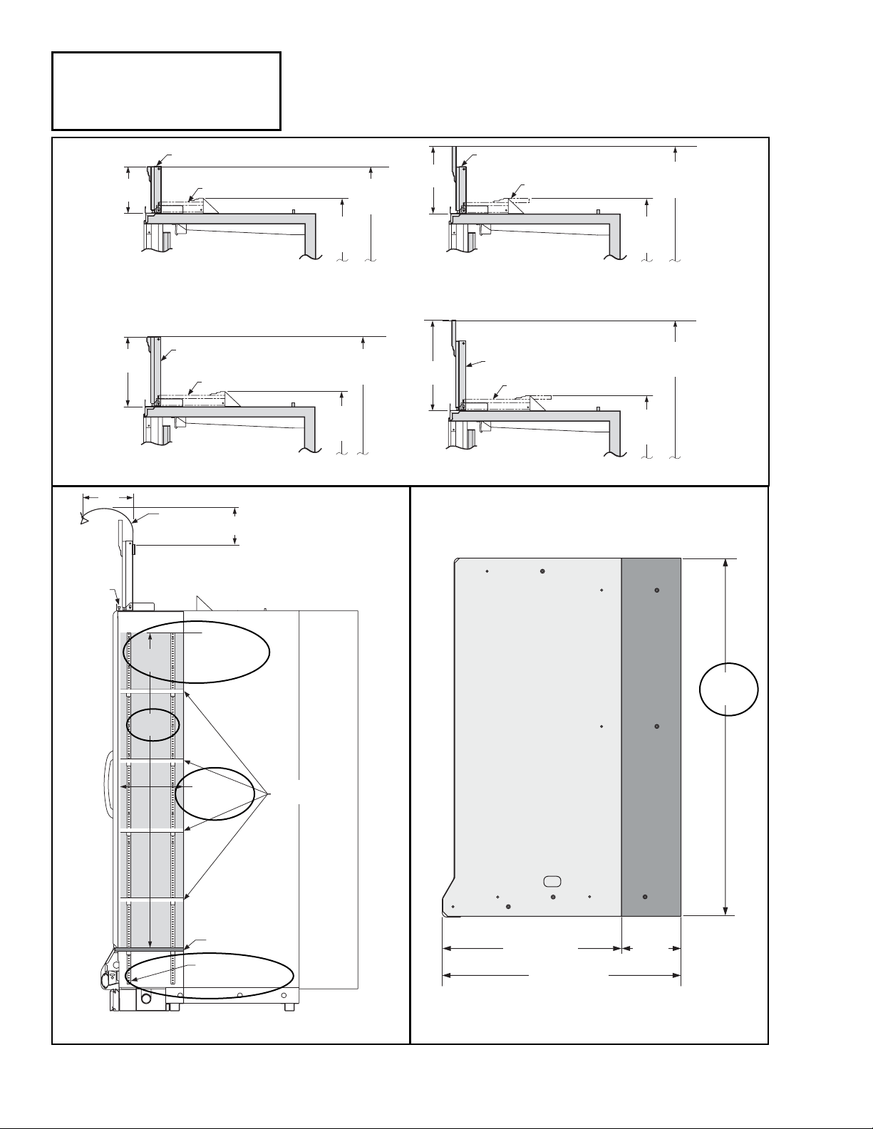
LifeLine Premier
RMN
With INNOVATOR Doors
Medium Temperature
Facade Options in Cross Section
Partition and End ProfilesDry Goods Cross-Section
11
(279)
Facade (Installed Position)
12 1/8
(308)
Facade (Shipping Position)
12 in. Straight Facade
18 1/8
(460)
Facade (Installed Position)
Facade (Shipping Position)
18 in. Straight Facade
Gooseneck
Lamp
(203)
Facade (Installed Position)
87 1/2
(2222)
Shipped
94 1/2
(2401)
Installed
17 1/2
(445)
Facade (Shipping Position)
87 1/2
(2222)
Shipped
99 7/8
(2537)
Installed
12 in. Arch Facade
100 1/2
(2553)
Installed
87 1/2
(2222)
Shipped
23 1/2
(597)
Facade (Installed Position)
Facade (Shipping Position)
18 in. Arch Facade
8
105 7/8
Installed
87 1/2
(2222)
Shipped
(2689)
Facade
Lamp
64 1/2
(1638)
Usable
Height
Maximum
Stocking Height
7
/8 (327)
12
Usable Depth
Fixed Shelf
Electrical Connection
for Shelf Lamps
Adjustable
Shelves
39 3/4 (1010)
51 3/4 (1314)
Bump Out
12
(305)
77 5/8
(1972)
Page 5

REFRIGERATION DATA
Note: This data is based on store temperature and
humidity levels that do not exceed NSF guidelines.
MEDIUM TEMP
Discharge Air °F 32
Evaporator °F 27
Unit Sizing °F 25
NSF NSF
BTU/HR/DOOR* TYPE ITYPE II
Temp (°F) /R.H. 75°/ 55% 80°/ 55%
Parallel 750 790
Conventional 790 830
*Optional Energy Efficient Fan motors
reduce refrigeration load by 109 Btu/hr/Door
DEFROST DATA
Frequency (hr) 24
Defrost Water (lb/Dr/day) 0.36
(± 15% based on case configuration and
product loading.)
ELECTRIC NA
Temp Term (°F) NA
Failsafe (minutes) NA
G
AS Not Recommended
O
FFTIME
60 minutes
CONVENTIONAL CONTROLS
Low Pressure Backup Control
CI/CO (Temp °F)* +20°/ +10°
Indoor Unit Only, Pressure Defrost
Termination (Temp °F)**
Not Recommended
**Use a Temperature Pressure Chart to
determine PSIG conversions.
Estimated Charge ***
2Dr 1.8lb 29 oz 0.8 kg
3Dr 2.7lb 43 oz 1.2 kg
4Dr 3.6lb 58 oz 1.6 kg
5Dr 4.6lb 74 oz 2.1 kg
***This is an average for all refrigerant types.
Actual refrigerant charge may vary by approx-
imately
0.5 lb (8 oz / 0.2 kg).
LifeLine Premier
RMN
With INNOVATOR Doors
Medium Temperature
51 3/4 (1314)
12
(305)
Bump Out
3 7/8
(97)
Electrical
Field Wiring
Connection
is at
Terminal
6 1/4
(159)
Facade (Installed Position)
Facade (Shipping Position)
23 1/2
(597)
Fan
Coil
62 1/2
(1588)
4
3
/4
(121)
22 Shelf
(559)
23
5
/8 (600)
Refrigeration Outlet
30 5/8 (778)
28 (711)
37 5/8 (956)
35 7/8 (911)
Electrical Stub-up Area
39 3/4 (1010)
37 (940)
36 1/4 (924)
83
(2108)
105 7/8
(2689)
Installed
18 in. Arch Facade
Shown
87 1/2
(2222)
Shipped
2 1/8
(54)
13 1/8
(333)
67
(1702)
Frame
65 1/2
(1664)
Door
82 1/4
(2089)
2 5/8
(67)
4 in. (102 mm)
Required Air Gap
Dimensions shown as inches and (mm).
LifeLine Premier
Narrow Footprint Reach-in
2, 3, 4 and 5 Door Models
5 of 11P/N 0510311_B
HUSSMANN CORPORATION • BRIDGETON, MO 63044-2483 U.S.A. • WWW.HUSSMANN.COM
NSF Certification
This merchandiser model is manufactured to meet ANSI/NSF
(National Sanitation Foundation) Standard #7 requirements for
construction, materials & cleanability.
LifeLine
Premier
RLN - RMN
See Page 4
for alternate
facade heights.
Page 6

Electrical Data
2Dr 3Dr 4Dr 5Dr
Number of Fans—12W 2 3 4 5
Amperes Watts
Merchandiser 2Dr 3Dr 4Dr 5Dr 2Dr 3Dr 4Dr 5Dr
Evaporator Fan
120V 60Hz Standard 1.30 1.95 2.60 3.25 100 150 200 250
120V 50Hz Standard 1.50 2.25 3.00 3.75 114 171 228 285
220V 60Hz Export 0.66 0.99 1.32 1.65 100 150 200 250
220V 50Hz Export 0.76 1.14 1.52 1.90 114 171 228 285
120V 60Hz Energy Efficient 0.60 0.90 1.20 1.50 36 54 72 90
220V 60Hz Energy Efficient 0.30 0.45 0.60 0.75 36 54 72 90
Door Anti-sweat Heaters (on fan circuit) NA
Frame Anti-sweat Heaters (on fan circuit)
120V 50/60Hz Standard 0.89 1.34 1.79 2.24 107 161 215 269
220V 50/60Hz Export 0.49 0.73 0.98 1.22 107 161 215 269
Minimum Circuit Ampacity
120V 60Hz Standard 2.39 3.49 4.59 5.69
120V 50Hz Standard 2.59 3.79 4.99 6.19
220V 60Hz Export 1.35 1.92 2.50 3.07
220V 50Hz Export 1.45 2.07 2.70 3.32
120V 60Hz Energy Efficient 1.69 2.44 3.19 3.94
220V 60Hz Energy Efficient 0.99 1.38 1.78 2.17
Maximum Over Current Protection 120V 20 20 20 20
Maximum Over Current Protection 220V 15 15 15 15
Defrost NA
Standard Vertical Lighting* 2Dr 3Dr 4Dr 5Dr 2Dr 3Dr 4Dr 5Dr
Hussmann EcoShine™ (24VDC) 0.45 0.68 0.90 1.13 54 81 108 135
Optional LED Lighting (24VDC)
Facade Lamps 0.79 1.17
1.54 1.92 19 28 37 46
Gooseneck Lamps (2 per merchandiser) 4.17 4.17 4.17 NA** 100 100 100 NA**
Dry Goods Lamps (both sides, 10 per side) 1.50 1.50 1.50 NA** 36 36 36 NA**
* Innovator or Innovator II.
** Dry Goods sections are not available on 5-Door models.
LifeLine Premier
RMN with Innovator Doors
Technical Data Sheet
6 of 11
U.S. & Canada 1-800-922-1919 • Mexico 1-800-522-1900
LifeLine Premier
RMN
With
INNOVATOR Doors
Medium Temperature
Hussmann recommends against frame heater cycling with
Innovator
doors to prevent door seals from freezing to the
frames and tearing.
Page 7

7 of 11P/N 0510311_B
HUSSMANN CORPORATION • BRIDGETON, MO 63044-2483 U.S.A. • WWW.HUSSMANN.COM
LifeLine Premier
RMN
With INNOVATOR Doors
Medium Temperature
Product Data
Recommended Usable Cube 1(Cu Ft/Dr) 22.80 ft3 /Dr (0.65 m3 /Dr)
AHRI Total Display Area 2(Sq Ft/Dr) 13.31 ft2/Dr (1.24 m2 /Dr)
Shelf Area 3(Sq Ft/Dr) 28.50 ft2/Dr (2.65 m2 /Dr)
1
AHRI Refrigerated Volume less shelving and other unusable space: Refrigerated Volume/Unit of Length, ft3/ft [m3/m]
2
Computed using AHRI 1200 standard methodology: Total Display Area, ft2[m2]/Unit of Length, ft [m]
3
Shelf surface area is composed of bottom deck plus standard shelf complement, as shown in the Hussmann
Product Reference Guide. The standard shelf complement for this model is (5) rows of 22-inch shelves.
Product Data (Dry Goods Area Only)
TOTAL Gross Usable Cube (Volume for 2 DG per merchandiser) 10.33 ft3/ (0.29 m3 )
ESTIMATED SHIPPING WEIGHT
4
2 Dr 3 Dr 4 Dr 5 Dr Solid End (each)
Standard LifeLine Premier Merchandiser (12-Inch Facade, no Arch)
lb (kg) 925 (420) 1167 (529) 1578 (716) 1945 (882) 65 (29)
Standard LifeLine Premier Merchandiser (18-Inch Facade, no Arch)
lb (kg) 935 (424) 1182 (536) 1598 (725) 1970 (894) 74 (34)
LifeLine Premier Merchandiser with Two (2) Bump Out Partitions (12-Inch Facade, no Arch)
lb (kg) 1093 (496) 1335 (606) 1746 (792) 2113 (958) N/A
LifeLine Premier Merchandiser with Two (2) Bump Out Partitions (18-Inch Facade, no Arch)
lb (kg) 1115 (506) 1362 (618) 1778 (806) 2150 (975) N/A
LifeLine Premier Merchandiser with Two (2) Dry Goods Sections, Four (4) Partitions (12-Inch Facade, no Arch)
lb (kg) 1382 (627) 1624 (737) 2035 (923) NA N/A
LifeLine Premier Merchandiser with Two (2) Dry Goods Sections, Four (4) Partitions (18-Inch Facade, no Arch)
lb (kg) 1411 (640) 1658 (752) 2074 (941) NA N/A
LifeLine Premier Merchandiser with
Two (2) Bump Out Partitions, Two (2) Dry Goods Sections, Two (2) Partitions (12-Inch Facade, no Arch)
lb (kg) 1421 (645) 1663 (754) 2074 (941) NA N/A
LifeLine Premier Merchandiser with
Two (2) Bump Out Partitions, Two (2) Dry Goods Sections, Two (2) Partitions (18-Inch Facade, no Arch)
lb (kg) 1452 (659) 1699 (771) 2115 (959) NA N/A
Add 10 lb (5 kg) for Arch
4
Actual weights will vary according to optional kits included.
Page 8

Refer to Innovator Reach-In
Glass Door, Installation and
Service manual, P/N 0425683,
for Innovator door and frame
replacement parts.
1
120V POWER
120V NEUTRAL
2P
Evaporator
Fans
26
2P
Frame Heaters
14
21
Offtime Defrost (standard)
Medium Temperature
BR
12
15 23
Terminal Blocks in Wireway
20
21
22
26
17
11 14
LIGHTS
(120V)
Refrigeration
Thermostat
(Optional)
Pink
2
}
To
Condensing
Unit
12
FANS & A.S.
(120V)
LIGHTS
(Neutral)
FANS & A.S.
(Neutral)
PBRORPOR
Removable External
Jumpers
120V POWER
NEUTRAL
Medium Temperature with
Offtime Defrost
20
OR
17
BR
OR
BR
11 22
Switch
CIRCLED NUMBERS = PARTS LIST ITEM NUMBERS
THESE ARE MARKER COLORS (WIRE MAY VARY.)
R = Red P = Purple 2P = Purple (2 Bands) DB = Dark Blue BK = Black
LB = Light Blue Pink = Pink BR =Brown Y =Yellow OR = Orange W = White
LifeLine Premier
RMN with Innovator Doors
Technical Data Sheet
8 of 11
U.S. & Canada 1-800-922-1919 • Mexico 1-800-522-1900
All components must have mechanical ground, and the merchandiser must be grounded.
= 120VPOWER
WARNING
= 120V NEUTRAL = FIELD GROUND
= CASE GROUND
Page 9

SWITCH
Optional
Lighting
LED
Fixtures
Hussmann
EcoShine
™
9 of 11P/N 0510311_B
HUSSMANN CORPORATION • BRIDGETON, MO 63044-2483 U.S.A. • WWW.HUSSMANN.COM
LIGHT
5
54
OUTPUT
WIREWAY
RED
BLACK
BLACK
WHITE
RED
BLACK
INPUT
3
2 DOOR LED LIGHT WIRING DIAGRAM
SWITCH
LIGHT
BLACK
INPUT
WHITE
RED
5
BLACK
RED
OUTPUT
BLUE
RED
4
RED
BLACK
3
BLUE
BLACK
RED
RED
BLACK
BLACK
RED
BLACK
TERMINAL BLOCK
20
RED
17
WHITE
BLACK
4
RED
BLACK
BLACK
5
RED
TERMINAL BLOCK
17
20
WHITE
BLACK
WIREWAY
BLACK
BLACK
3 DOOR LED LIGHT WIRING DIAGRAM
SWITCH
LIGHT
BLACK
RED
5
BLACK
WHITE
BLACK
INPUT
RED
4
RED
BLACK
BLACK
RED
BLUE
OUTPUT
RED
4
RED
BLACK
BLACK
3
RED
4
RED
BLACK
BLACK
5
RED
TERMINAL BLOCK
17
20
WHITE
BLACK
BLACK
WIREWAY
4 DOOR LED LIGHT WIRING DIAGRAM
SWITCH
LIGHT
RED
5
BLACK
WHITE
4
RED
RED
BLACK
BLACK
RED
OUTPUT
3
RED
4
RED
BLACK
BLACK
BLACK
INPUT
WHITE
4
RED
RED
BLACK
INPUT
BLACK
BLACK
RED
BLUE
OUTPUT
RED
4
RED
BLACK
BLACK
3
BLUE
TERMINAL BLOCK
5
RED
BLACK
WIREWAY
17 20
BLACK
BLACK
BLACK
5 DOOR LED LIGHT WIRING DIAGRAM
WARNING
All components must have mechanical ground, and the merchandiser must be grounded.
CIRCLED NUMBERS = PARTS LIST ITEM NUMBERS
R = Red Y = Yellow G = Green BL = Blue BK = Black W = White
= 120VP
OWER = 120V NEUTRAL = FIELD GROUND = CASE GROUND
Page 10

LifeLine Premier
RMN with Innovator Doors
Technical Data Sheet
10 of 11
U.S. & Canada 1-800-922-1919 • Mexico 1-800-522-1900
Optional Lighting Circuits
LifeLine Premier
RMN
With INNOVATOR Doors
Medium Temperature
CIRCLED NUMBERS = PARTS LIST ITEM NUMBERS
R = Red P = Purple 2P = Purple (2 Bands)
DB = Dark Blue BK = Black BL = Blue
BR =Brown Y =Yellow OR = Orange W = White
THESE ARE MARKER COLORS (WIRE MAY VARY.)
Optional External Facade LED Wiring
120V AC
from Wireway
W
BK
W
BK
Light
Switch
BK
W
3
Power Supply
24V DC
17 20
OR
OR
Terminal Block
Facade Light
Assembly
66666
BL
R
Optional External Gooseneck LED Wiring
120V AC
from Wireway
W
BK
W
BK
OR
OR
Terminal Block
Switch
17 20
Light
BK
W
3
Power Supply
24V DC
R
BL
R
BL
BL
R
BL
R
BL
BL
R
BL
R
7
R
BL
R
Gooseneck
Light
Gooseneck
Light
Enclosure
or Wireway
R
BL
WARNING
All components must have mechanical ground, and the merchandiser must be grounded.
= 120VPOWER
= 120V NEUTRAL = FIELD GROUND
= CASE GROUND
Page 11

11 of 11P/N 0510311_B
HUSSMANN CORPORATION • BRIDGETON, MO 63044-2483 U.S.A. • WWW.HUSSMANN.COM
LifeLine Premier
RMN
With INNOVATOR Doors
Medium Temperature
Optional Lighting Circuits
CIRCLED NUMBERS = PARTS LIST ITEM NUMBERS
R = Red P = Purple 2P = Purple (2 Bands)
DB = Dark Blue BK = Black BL = Blue
BR =Brown Y =Yellow OR = Orange W = White
THESE ARE MARKER COLORS (WIRE MAY VARY.)
Optional External Dry Goods LED Wiring
120 VAC
from Wireway
BK
W
W
BK
W
BK
OR
OR
Terminal Block
17 20
Light Switch
BL
BL
BL
BK
W
8
3
Input
Power Supply
R
RBL
R
RBL
RBL
RBL
R
Output
BL
R
BL
BL
8
BL
R
R
RBL
R
RBL
RBL
RBL
BL
Pilaster / Shelf Standard
BL
BL
BL
8
Enclosure
or Wireway
BL
Pilaster / Shelf Standard
BL
BL
BL
8
R
Pilaster / Shelf Standard
R
RBL
R
R
Shelf Lamps (up to 10 per end)
WARNING
All components must have mechanical ground, and the merchandiser must be grounded.
= 120VPOWER
= 120V NEUTRAL = FIELD GROUND
= CASE GROUND
R
Pilaster / Shelf Standard
R
RBL
R
R
 Loading...