

Page 1
Item Part # Description Wiring Item #
F
AN ASSEMBLIES, AND THERMOSTATS
A. 25W Standard Energy Efficient Fan Assembly (1)
MO.4410549 Fan Motor, Evaporator
FB.0315470 Fan Blade
B. CT.4440256 Standard Non-adjustable Defrost (2)
Thermostat
C. Optional Adjustable Refrigeration Thermostat (3)
D. CT.4481089 Defrost Limit Thermostat (4)
E. CT.4440353 Relay Control Thermostat or (5)
Fan and Anti-sweat Heater
Thermostat
RELAYS
F. RL.4480238 Anti-Sweat Control Relay (120V) (6)
G. RL.4480237 Fan Control Relay (208V) (7)
H
EATERS
H. Electric Defrost Heaters (208V) (8)
HE.4850354 (1) 2 Door Models
HE.4850355 (1) 3 Door Models
HE.4850356 (1) 4 Door Models
HE.4850357 (1) 5 Door Models
I. Drain Pan Heater – Electric & Koolgas (120V) (9)
HE.4851029 (1) 2 Door Models
HE.4851030 (1) 3 Door Models
HE.4850987 (1) 4 Door Models
HE.4850988 (1) 5 Door Models
J. Koolgas Supplemental Heater – Plenum (120V) (10)
HE.4850576 (1) 2 Door Models
HE.4850577 (1) 3 Door Models
HE.4850510 (1) 4 Door Models
HE.4850578 (1) 5 Door Models
Item Part # (Qty) Description Wiring Item #
HEATERS (CONTINUED)
K. Koolgas Supplemental Drain Pan Heater – Bottom (120V) (11)
HE.4850350 (2) 2 Door Models
HE.4850506 (2) 3 Door Models
HE.4850661 (2) 4 Door Models
HE.4850507 (2) 5 Door Models
LED F
IXTURES AND POWER SUPPLY
L. EP.4481668 Power Supply (12)
M. Door Lamp, LED
ECOSHINE
BU.4441565 3500K Wide Angle 67-in. Center (13)
BU.4441567 4100K Wide Angle 67-in. Center (13)
BU.4441566 3500K Wide Angle 67-in. End (14)
BU.4441568 4100K Wide Angle 67-in. End (14)
ECOSHINE EP (ENERGY PLUS)
BU.4441656 3500K Wide Angle 67-in. Center (13)
BU.4441658 4100K Wide Angle 67-in. Center (13)
BU.4441657 3500K Wide Angle 67-in. End (14)
BU.4441659 4100K Wide Angle 67-in. End (14)
N. Facade Lamp, LED (15)
BU.4441411 2900K 29.5 In. Length
BU.4441412 2900K 30.5 In. Length
O. BU.4441413 Gooseneck Lamp (16)
P. Dry Goods Lamp, LED
BU.4441414 3500K (17)
(NOTE: Gooseneck Lamp and Dry Goods Lamp
cannot be applied to same merchandiser.)
SH.4991645 KLU9600
Shelf, Lighted, Pearwood
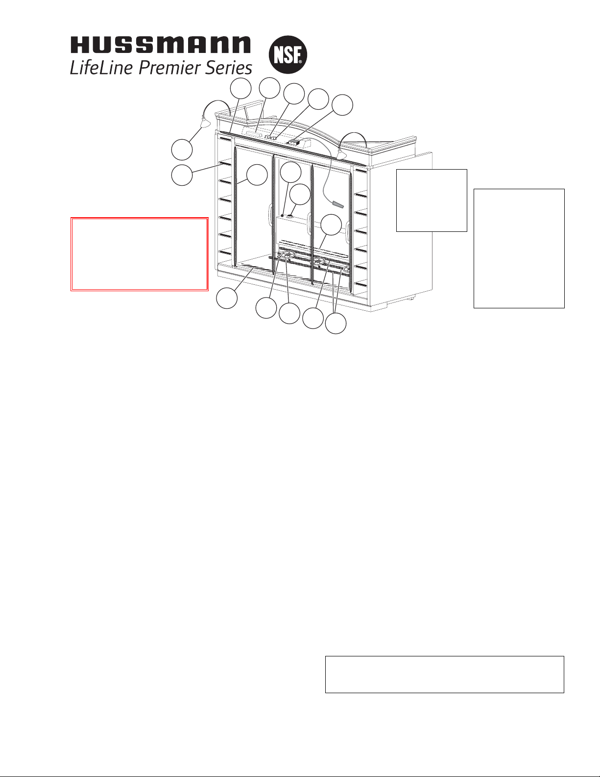
®
LifeLine Premier
RLT
with
INNOVATOR
Doors
Technical Data Sheet
P/N 0510313_A
NSF
®
Certified
April 2010
We reserve the right to
change or revise specifications and product design
in connection with any
feature of our products.
Such changes do not
entitle the buyer to
corresponding changes,
improvements, additions
or replacements for
equipment previously sold
or shipped.
OPTIONS SHOWN:
• Lighted Facades
• Arch Facade
• Gooseneck Lamps
• Dry Goods Storage
• Bump Out Partitions
Warning:
Terminal block NOT for
case-to-case
wire connection!
P/N0510313A
©2010 HUSSMANN CORPORATION • BRIDGETON, MO 63044-2483 U.S.A.
U.S. & CANADA 1-800-922-1919 • MEXICO 1-800-522-1900 • WWW.HUSSMANN.COM
Refer to INNOVATOR REACH-IN GLASS DOOR
INSTALLATION AND SERVICE MANUAL, P/N 0425683,
for Innovator door and frame replacement parts.
NOTE: Revision A is original issue.
N
L
G
O
P
M
B
D
I
E
A
F
C
H
J
K
Page 2
LifeLine Premier
RLT with Innovator Doors
Technical Data Sheet
2 of 12
U.S. & CANADA 1-800-922-1919 • MEXICO 1-800-522-1900
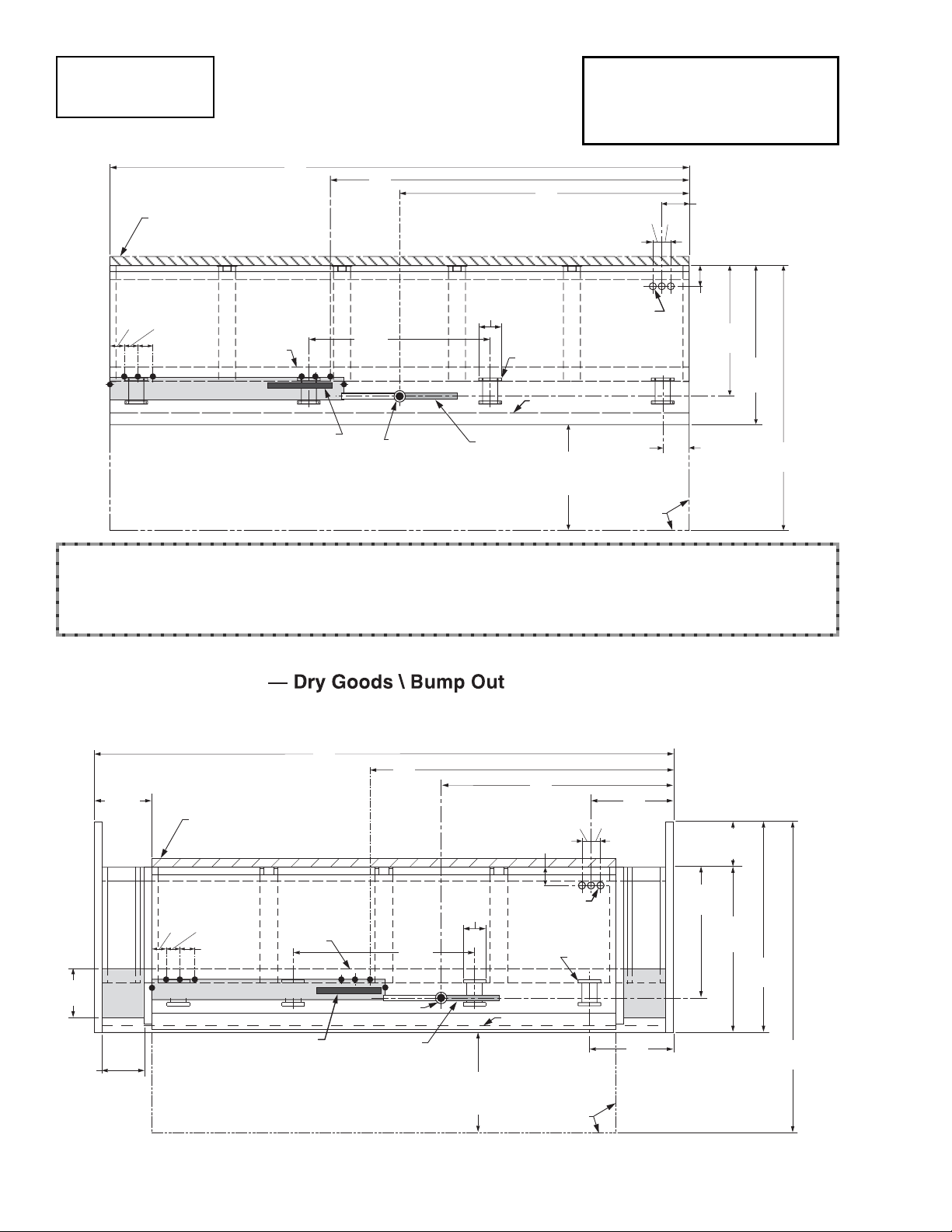
Tall Reach-In
2, 3, 4 & 5 Door
Engineering
Plan Views
Base 5-door merchandiser is shown above, without Bump Out, Dry Goods sections, Partitions or Ends.
Illustrated below is a 4-door merchandiser with Dry Goods cabinets and Bump Out end partitions.
Refer to chart on Page 3 for detailed dimensional information on options.
Dimensions shown as inches & (mm).
Dimensions shown as inches and (mm).
LifeLine Premier
RLT
Plan View
02-2010
PHYSICAL DATA
Merchandiser Drip Pipe (in.) 1 1/4
Merchandiser Liquid Line (in.)
3
/8
Merchandiser Suction Line (in.)
7
/8
4 in. (102 mm) Minimum Air Gap
from Merchandiser Insulated Panel
to Wall or Flat Surface
23/4
21/2
(70)
(64)
21/2
(64)
Electrical Wireway (on top)
Skid/
External
Base
A
B
48
(1219)
6
(152)
C
Bottom
Front
Support
Splashguard
D
3
2
23/8
Refrigeration
Outlets
(on top)
(60)
(60)
/8
1
5
(140)
/2
34
(879)
5
/8
42
(1070)
1
/8
Relay & Terminal
Block Location
Waste
Outlet
Front
5-Door Shown
Water Seal
(see note ***)
28
(711)
from Bumper
E
Door Swing
Clearance
LifeLine Premier RLT
Plan View
2, 3 & 4 Door
1
15
/4
(387)
A
4 in. (102 mm) Minimum Air Gap
from Merchandiser Insulated Panel
to Wall or Flat Surface
B
C
23/8
1
5
/2
(140)
D
23/8
(60)
(60)
12
(305)
1
70
(1782)
/8
12 7/8
(327)
10 3/4
(273)
Shelf
Area
Usable
Width
23/4
(70)
21/2
(64)
21/2
(64)
Skid/
External
Base
48
(1219)
Electrical Wireway (on top)
Waste Outlet
Relay & Terminal
Block Location
Water Seal
(see note ***)
Front
4-Door Shown
6
(152)
28
(711)
from Bumper
Refrigeration
Outlets
(on top)
Splashguard
Door Swing
Clearance
Bottom
Front
Support
5
34
/8
(879)
1
42
/8
(1070)
Shelf
Area
E
1
54
(1375)
/8
82
(2086)
1
/8
Page 3
3 of 12P/N 0510313_A
HUSSMANN CORPORATION • BRIDGETON, MO 63044-2483 U.S.A. • WWW.HUSSMANN.COM
LifeLine Premier
RLT
With INNOVATOR Doors
Frozen Food & Ice Cream
Plan View Dimensions for
LifeLine Premier
Options
Abbreviations: DG = Dry Goods section BO = Bump Out
General 2 Dr 3 Dr 4 Dr 5 Dr
(A) Merchandiser Length 62 (1575) 92
1
/2 (2350) 122 7/8 (3121) 153 3/8 (3896)
(A) Merchandiser Length BO includes 2 bump-out ends 66 (1676) 96 1/2 (2451) 126 7/8 (3222) 157 3/8 (3997)
(A) Merchandiser Length DG includes 4 ends and dry goods cabinets 92 1/
2 (2350) 123 (3124) 153
3
/
8 (3896) NA
Maximum O/S dimension of merchandiser back to front * 42
1
/8 (1070) 42 1/8 (1070) 42 1/8 (1070) 42 1/8 (1070)
Maximum O/S dimension of merchandiser back to front BO * † 54 1/
8 (1375) 54
1
/
8 (1375) 54
1
/
8 (1375) 54
1
/
8 (1375)
*
Includes bumper. Add 26 1/
2 in. (673 mm) for door swing.
† Merchandiser dimension plus 12 inch bump out
Interior width of dry goods cabinet 10 3/
4 (273) 10
3
/
4 (273) 10
3
/
4 (273) NA
Interior depth of dry goods cabinet 12
7
/
8 (327) 12
7
/
8 (327) 12
7
/
8 (327) NA
Back of merchandiser to front of splashguard 39 (991) 39 (991) 39 (991) 39 (991)
Back of merchandiser to front of splashguard BO 51 (1295) 51 (1295) 51 (1295) 51 (1295)
Width of Skid rail 3
3
/4 (95) 3 3/4 (95) 3 3/4 (95) 3 3/4 (95)
Width of Bottom Front Support 6 (152) 6 (152) 6 (152) 6 (152)
Stub-up area between front support and splashguard 7 1/
8 (181) 7
1
/
8 (181) 7
1
/
8 (181) 7
1
/
8 (181)
Electrical Service
(B) RH end of merchandiser to the center of nearest knockout 2
3
/
4 (70) 33
1
/
4 (845) 63
5
/
8 (1616) 94
1
/
8 (2391)
(B) RH end of merchandiser to the center of nearest knockout BO 4
3
/4 (121) 35 1/4 (895) 65 5/8 (1667) 96 1/8 (2442)
(B) RH end of merchandiser to the center of nearest knockout DG 18 (457) 48 1/
2 (1232) 78
7
/
8 (2003) NA
RH end of merchandiser to the center of LH knockout 59
1
/
4 (1505) 89
3
/
4 (2280) 120
1
/
8 (3051) 150
5
/
8 (3826)
Back O/S of merchandiser to center of knockout 31
5
/8 (803) 31 5/8 (803) 31 5/8 (803) 31 5/8 (803)
Back O/S of merchandiser to center of knockout BO † 43 5/
8 (1108) 43
5
/
8 (1108) 43
5
/
8 (1108) 43
5
/
8 (1108)
Wireway Length 62 (1575) 62 (1575) 62 (1575) 62 (1575)
** NOTE: Electrical Field Wiring Connection Point is at terminal.
Waste Outlet
(C) Right end of merchandiser to center of waste outlet 23 7/8 (606) 54 1/4 (1378) 46 1/4 (1175) 76 5/8 (1946)
(C) Right end of merchandiser to center of waste outlet BO 25 7/
8 (657) 56
1
/
4 (1429) 48
1
/
4 (1226) 78
5
/
8 (1997)
(C) Right end of merchandiser to center of waste outlet DG 39
1
/8 (994) 69 1/2 (1765) 61 1/2 (1562) NA
Back O/S of merchandiser to center of waste outlet 34 5/8 (879) 34 5/8 (879) 34 5/8 (879) 34 5/8 (879)
Back O/S of merchandiser to center of waste outlet BO † 46 5/8 (1184) 46 5/8 (1184) 46 5/8 (1184) 46 5/8 (1184)
Water Seal
Edge of water seal to center of waste outlet 13 (330) 13 (330) 13 (330) 13(330)
Schedule 40 PVC drip pipe 1
1
/
4 (32) 1
1
/
4 (32) 1
1
/
4 (32) 1
1
/
4 (32)
*** NOTE: Field installed water seal outlets, tees, and connectors are shipped with merchandiser.
Refrigeration Outlet
(D) RH end of merchandiser to center of middle RH refrigeration outlet 7 1/4 (184) 7 1/4 (184) 7 1/4 (184) 7 1/4 (184)
(D) RH end of merchandiser to center of middle RH refrigeration outlet BO 9 1/4 (235) 9 1/4 (235) 9 1/4 (235) 9 1/4 (235)
(D) RH end of merchandiser to center of middle RH refrigeration outlet DG 22 1/2 (572) 22 1/2 (572) 22 1/2 (572) NA
Back O/S of merchandiser to center of refrigeration outlets 5 1/2 (140) 5 1/2 (140) 5 1/2 (140) 5 1/2 (140)
Back O/S of merchandiser to center of refrigeration outlets BO † 17 1/2 (445) 17 1/2 (445) 17 1/2 (445) 17 1/2 (445)
(E) Outside bottom front supports from end of merchandiser 7 (178) 7 (178) 7 (178) 7 (178)
(E) Outside bottom front supports from end of merchandiser BO 9 (229) 9 (229) 9 (229) 9 (229)
(E) Outside bottom front supports from end of merchandiser DG †† 26 1/2 (673) 26 3/4 (679) RH 26 1/4 (667) NA
37 1/2 (952) LH
Center bottom front support from Centerline 24 (610) 24 (610) 24 (610) 24 (610)
Center bottom front support from Centerline BO 24 (610) 24 (610) 24 (610) 24 (610)
Center bottom front support from Centerline DG †† 6 3/4 (171) LH 8 3/4 (222) RH 24 (610) NA
††Distance between Center and Outside supports will vary
Page 4
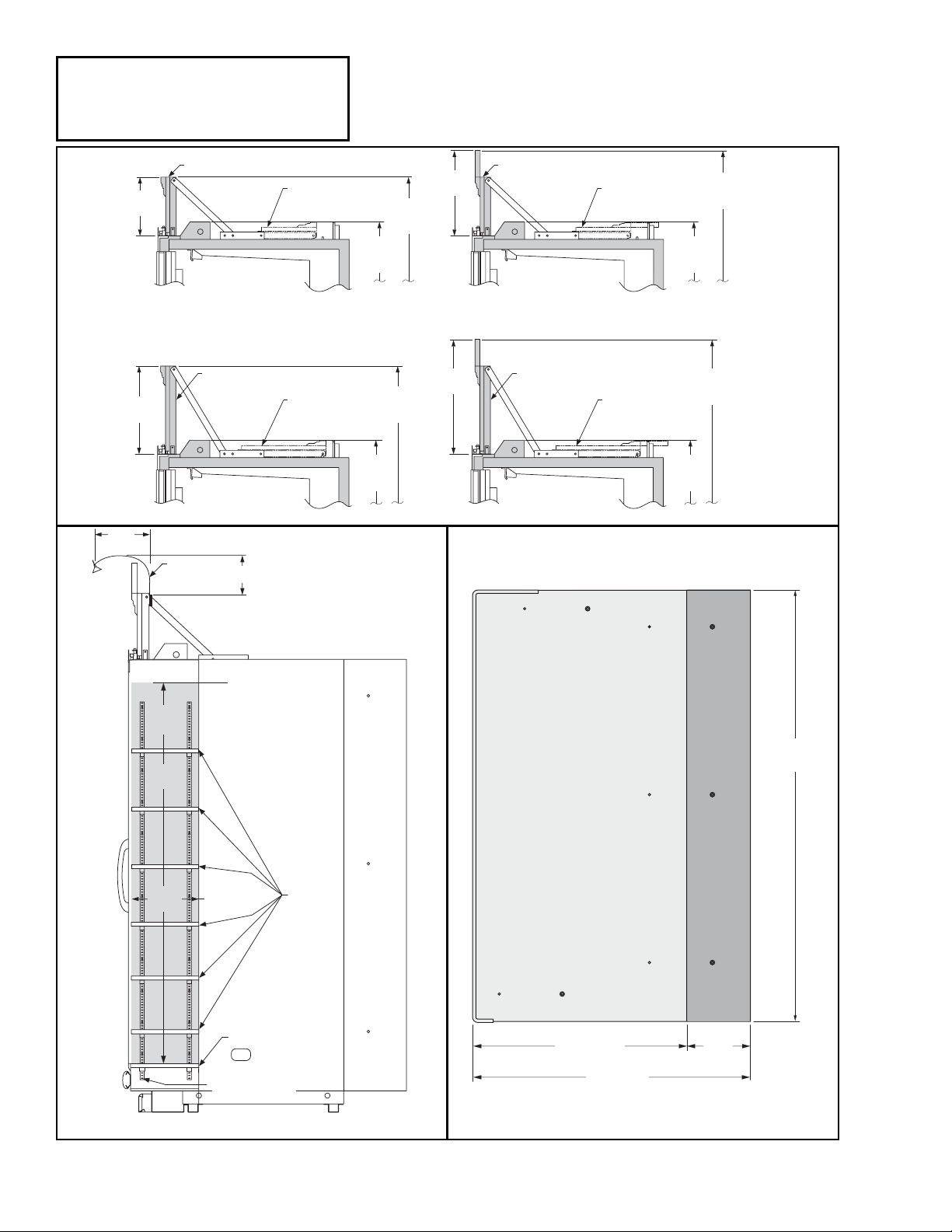
Facade Options in Cross Section
LifeLine Premier
RLT with Innovator Doors
Technical Data Sheet
4 of 12
U.S. & CANADA 1-800-922-1919 • MEXICO 1-800-522-1900
LifeLine Premier
RLT
With INNOVATOR Doors
Frozen Food & Ice Cream
Std End and Bump Out End Profiles
Dry Goods Cross-Section
11
(279)
Facade (Installed Position)
12 1/8
(308)
12 in Straight Facade
Facade (Installed Position)
18 1/8
(460)
18 in Straight Facade
Gooseneck
Lamp
8 (203)
Facade (Installed Position)
Facade
(Shipped Position)
89
(2261)
Shipped
98 1/8
(2492)
Installed
17 1/2
(445)
12 in Arch Facade
Facade (Installed Position)
18 in Arch Facade
Facade
(Shipped Position)
104 1/8
Installed
89
(2261)
Shipped
(2644)
23 1/2
(597)
Facade
(Shipped Position)
Facade
(Shipped Position)
89
(2261)
Shipped
109 1/2
(2781)
Installed
89
(2261)
Shipped
103 1/2
(2629)
Installed
Maximum
Stocking Height
73
(1854)
Usable
Height
Usable
Depth
12 7/8
(327)
Fixed Shelf
Electrical Connection
for Shelf Lamps
(Front pilasters only)
Adjustable
Shelves
82 1/4
(2089)
Bump Out
41 (1041)
12
(305)
53 (1346)
Page 5

REFRIGERATION DATA
Note: This data is based on store temperature
and humidity that does not exceed 75°F and
55% R.H.
FF IC
Discharge Air (°F) –5 –12
Evaporator (°F) –11 –19
Unit Sizing (°F) –14 –22
Btu/hr/Door
Parallel
1280 1355
Conventional
1305 1385
DEFROST DATA
FF IC
Frequency (hr) 24 24
Defrost Water (lb/Dr/day) 1.2 1.3
(± 15% based on merchandiser configuration
and product loading.)
ELECTRIC FF IC
Temp Term (°F) 54° 54°
Failsafe (minutes) 48 48
GAS
Duration (minutes) 22 22
O
FFTIME Not Recommended
CONVENTIONAL CONTROLS
Low Pressure Backup Control
FF IC
CI/CO (Temp °F)* –18°/ –34° – 26°/ –45°
Indoor Unit Only, Pressure Defrost
Termination (Temp °F)*
Not Recommended
*Use a Temperature Pressure Chart to determine PSIG conversions.
Estimated Charge **
2 Dr 3.2 lb 51 oz 1.5 kg
3 Dr 4.7 lb 75 oz 2.1 kg
4 Dr 6.3 lb 101 oz 2.9 kg
5 Dr 8.1 lb 130 oz 3.7 kg
**This is an average for all refrigerant types.
Actual refrigerant charge may vary by approximately half a pound.
LifeLine Premier
RLT
With INNOVATOR Doors
Frozen Food & Ice Cream
18 in Arch Facade Shown
3 1/2
(89)
1 5/8 (41)
FAN
C
O
I
L
7 1/8 (181)
6 1/8
(156)
109 1/2
(2781)
Installed
89
(2261)
Shipped
23 1/2
(597)
Facade
(Installed Position)
Facade
(Shipped Position)
29 5/8 (752)
30 3/4 (781)
42 1/8 (1070)
20 (508)
22
(559)
63 5/8 (1616)
86
(2184)
74 1/2
(1892)
Frame
73 1/8
(1857)
Door
31 5/8 (803)
39 (991)
8 1/4 (210)
24 5/8
(625)
54 1/8 (1375)
12
(305)
Bump Out
4 3/4
(121)
40 (1016)
40 5/8 (1032)
Dimensions shown as inches and (mm).
LifeLine Premier
Tall Reach-in 2, 3, 4 and 5 Door Models
5 of 12P/N 0510313_A
HUSSMANN CORPORATION • BRIDGETON, MO 63044-2483 U.S.A. • WWW.HUSSMANN.COM
LifeLine
Premier
RLT
See Page 4
for alternate
facade heights.
NSF®Certification
This merchandiser model is manufactured to meet ANSI/NSF
®
(National
Sanitation Foundation) Standard #7 requirements for construction, materials
& cleanability.
Page 6

U.S. & CANADA 1-800-922-1919 • MEXICO 1-800-522-1900
Electrical Data
2Dr 3Dr 4Dr 5Dr
Number of Fans — 25W 2 3 4 5
Amperes Watts
Merchandiser 2Dr 3Dr 4Dr 5Dr 2Dr 3Dr 4Dr 5Dr
Evaporator Fan
120V 60Hz Standard
120V 50Hz Standard
220V 60Hz Export
220V 50Hz Export
120V 60Hz Standard Energy Efficient 2.00 3.00 4.00 5.00 160 240 320 400
220V 60Hz Export Energy Efficient 1.00 1.50 2.00 2.50 160 240 320 400
Door Anti-sweat Heaters (on fan circuit)
120V 50/60Hz Standard 1.35 2.03 2.70 3.38 162 243 324 405
220V 50/60Hz Export 0.74 1.10 1.47 1.84 162 243 324 405
Frame Anti-sweat Heaters (on fan circuit)
120V 50/60Hz Standard 0.96 1.43 1.92 2.40 115 172 230 288
220V 50/60Hz Export 0.52 0.78 1.05 1.31 115 172 230 288
Minimum Circuit Ampacity
120V 60Hz Standard
120V 50Hz Standard
220V 60Hz Export
220V 50Hz Export
120V 60Hz Standard Energy Efficient 4.51 6.66 8.82 10.98
220V 60Hz Export Energy Efficient 2.46 3.58 4.72 5.85
Maximum Over Current Protection 120V 20 20 20 20
Maximum Over Current Protection 220V 20 20 20 20
Defrost
Drain Heater (Koolgas or Electric)
120V 60Hz Standard 1.00 1.50 2.00 2.50 120 180 240 300
220V 50Hz Export 0.50 0.75 1.00 1.25 110 165 220 275
Koolgas Supplemental Heaters
120V 60Hz Standard 4.30 6.78 9.18 11.58 516 814 1102 1390
220V 50Hz Export 2.35 3.70 5.01 6.32 472 744 1007 1270
Electric Defrost Heater
208V 60Hz Standard 7.70 11.50 15.40 19.20 1600 2400 3200 4000
220V 50Hz Export 6.70 10.00 13.30 16.60 1465 2200 2930 3660
Standard Vertical Lighting (Innovator) 2Dr 3Dr 4Dr 5Dr 2Dr 3Dr 4Dr 5Dr
H
USSMANN ECOSHINE™ (120V) 0.45 0.68 0.90 1.13 54 81 108 135
H
USSMANN ECOSHINE™ [220V (EXPORT)] 0.25 0.37 0.49 0.61 54 81 108 135
Optional Lighting
H
USSMANN ECOSHINE™ ENERGY PLUS (120V) 0.30 0.45 0.60 0.75 36 54 72 90
H
USSMANN ECOSHINE™ ENERGY PLUS [220V (EXPORT)] 0.16 0.25 0.33 0.41 36 54 72 90
Facade LED Lamps 0.79 1.17 1.54 1.92 19 28 37 46
Gooseneck Halogen Lamps (2 per merchandiser) 4.17 4.17 4.17 NA* 100 100 100 NA*
Dry Goods LED Lamps (both sides, 10 per side) 1.50 1.50 1.50 NA* 36 36 36 NA*
* Dry Goods sections are not available on 5-Door models.
LifeLine Premier
RLT with Innovator Doors
Technical Data Sheet
6 of 12
LifeLine Premier
RLT
With
INNOVATOR Doors
Frozen Food & Ice Cream
Hussmann recommends against frame heater cycling with
Innovator
doors to prevent door seals from freezing to the
frames and tearing.
Page 7

7 of 12P/N 0510313_A
HUSSMANN CORPORATION • BRIDGETON, MO 63044-2483 U.S.A. • WWW.HUSSMANN.COM
LifeLine Premier
RLT
With INNOVATOR Doors
Frozen Food & Ice Cream
Product Data (Refrigerated Area Only)
Recommended Usable Cube 1(Cu Ft/Dr) 24.95 ft3 /Dr (0.71 m3 /Dr)
AHRI Total Display Area 2(Sq Ft/Dr) 13.59 ft2/Dr (1.26 m2 /Dr)
Shelf Area 3(Sq Ft/Dr) 32.38 ft2/Dr (3.01 m2 /Dr)
1
AHRI Refrigerated Volume less shelving and other unusable space: Refrigerated Volume/Unit of Length, ft3/ft [m3/m]
2
Computed using AHRI 1200 standard methodology: Total Display Area, ft2[m2]/Unit of Length, ft [m]
3
Shelf surface area is composed of bottom deck plus standard shelf complement, as shown in the Hussmann
Product Reference Guide. The standard shelf complement for this model is (6) rows of 22-inch shelves.
Product Data (Dry Goods Area Only)
TOTAL Gross Usable Cube (Volume for 2 DG per merchandiser) 11.69 ft3 / (0.33 m3 )
ESTIMATED SHIPPING WEIGHT
4
2 Dr 3 Dr 4 Dr 5 Dr Solid End (each)
Standard LifeLine Premier Merchandiser (12-Inch Facade, no Arch)
lb (kg) 1057 (479) 1385 (628) 1715 (778) 2024 (918) 85 (39)
Standard LifeLine Premier Merchandiser (18-Inch Facade, no Arch)
lb (kg) 1067 (484) 1400 (635) 1735 (787) 2049 (929) 80 (36)
LifeLine Premier Merchandiser with Two (2) Bump Out Partitions (12-Inch Facade, no Arch)
lb (kg) 1236 (561) 1564 (709) 1894 (859) 2203 (999) N/A
LifeLine Premier Merchandiser with Two (2) Bump Out Partitions (18-Inch Facade, no Arch)
lb (kg) 1259 (571) 1592 (722) 1927 (874) 2241 (1017) N/A
LifeLine Premier Merchandiser with Two (2) Dry Goods Sections, Four (2) Partitions (12-Inch Facade, no Arch)
lb (kg) 1537 (697) 1865 (846) 2195 (996) NA NA
LifeLine Premier Merchandiser with Two (2) Dry Goods Sections, Four (2) Partitions (18-Inch Facade, no Arch)
lb (kg) 1567 (711) 1900 (862) 2235 (1014) NA NA
LifeLine Premier Merchandiser with
Two (2) Bump Out Partitions, Two (2) Dry Goods Sections, Two (2) Partitions (12-Inch Facade, no Arch)
lb (kg) 1576 (715) 1904 (864) 2234 (1013) NA N/A
LifeLine Premier Merchandiser with
Two (2) Bump Out Partitions, Two (2) Dry Goods Sections, Two (2) Partitions (18-Inch Facade, no Arch)
lb (kg) 1609 (730) 1942 (881) 2277 (1033) NA N/A
Add 10 lb (5 kg) for Arch
4
Actual weights will vary according to optional kits included.
Page 8

LifeLine Premier
RLT with Innovator Doors
Technical Data Sheet
8 of 12
C
OR
120V POWER
OR
Switch
17
20
NEUTRAL
C
208V
Evaporator Fan
Relay Coil
1
3
R
R
Defrost Heater
R
5
4
BK
7
R
N.C.
7
8
8
Defrost Limit
208V
208V
1
2
3
4
6
O.O.R.
BK
R P
W
BRORRRRBKBKRRBKP2PBK BK ORBK 2P Y
Defrost Termination
Thermostat
Refrigeration
Thermostat
(Optional)
Pink
2
3
}
To
Condensing
Unit
A.S. Relay
Coil
BR
Evaporator Fans
1
Fan Relay
COM
N.O.
Rod Heater (Drain)
9
Y
Y
N.C.
7
7
1
3
W
Relay Control
25
Fan Relay
BK
5
6
COM
N.C.
6
A.S. Relay
24
Door A.S. Heaters
Frame A.S. Heaters
21
22
2P
P
2P
P
12
11
10
120V POWER
16
13
Terminal Blocks in Raceway
Low Temperature with
Electric Defrost
20
21
22
26
17
1234
56 7
81011 1413 16
LIGHTS
(120V)
DEFROST HEATERS
(208V)
CAUTION: When multiplexing
merchandisers equipped with defrost
heaters, if branch circuit overcurrent
protection is larger than the
circuit load, then additional
supplemental overcurrent protection
may be required per NEC Articles
210 and 240.
Low Temperature
24 2512
FANS & A.S.
(120V)
LIGHTS
(Neutral)
FANS & A.S. (Neutral)
Permanent Internal
Jumpers
14
26
C.O.R.
Removable External
Jumpers
DB
C.O.R.
2
Defrost Termination
Thermostat
FIELD WIRED
DB
NEUTRAL
Dark Blue
Refer to Innovator Reach-In
Glass Door, Installation and
Service manual, P/N 0425683,
for Innovator door and frame
replacement parts.
C
6
120V
Fan Relay
N.C.
120V Fan
Relay Coil
6
CIRCLED NUMBERS = PARTS LIST ITEM NUMBERS
THESE ARE MARKER COLORS (WIRE MAY VARY.)
R = Red P = Purple 2P = Purple (2 Bands) DB = Dark Blue BK = Black
LB = Light Blue Pink = Pink BR =Brown Y =Yellow OR = Orange W = White
BK
BK BK
Electric Defrost Sequence - Low Temperature
1. Power from the defrost contactor energizes Defrost Heaters and 208V Evaporator Fan Relay Coil (7). Relay Contacts open the fan
circuit and energizes the Drain Pan Heater.
2. If the Defrost Heater raises internal air temperature above 90°F, the Defrost Limit Thermostat (4) will open.
3. Temperature rise of the evaporator closes the Relay Control Thermostat (5) at about 35°F, energizing the 120V A.S. and Fan Relay
Coils (6). These relays’ contacts open the Frame and Door Heater Circuits, and prevent the Fan Circuit from energizing upon defrost
termination.
4. When Defrost Termination Thermostat ends defrost period, the defrost contactor opens the Defrost Heater and Evaporator Fan Relay
Coil Circuits. The Drain Pan Heater goes off.
5. Temperature fall of the evaporator opens the Relay Control Thermostat (5) at about 20°F, de-energizing the A.S. and Fan Relay
Coils (6). A.S. Relay Contacts close the Frame and Door Heater Circuits, and Fan Circuit.
U.S. & CANADA 1-800-922-1919 • MEXICO 1-800-522-1900
Page 9

9 of 12P/N 0510313_A
HUSSMANN CORPORATION • BRIDGETON, MO 63044-2483 U.S.A. • WWW.HUSSMANN.COM
120V POWER
Gas Defrost Sequence - Low Temperature
1. Defrost vapor enters evaporator causing a rise in temperature. At about 35°F the Relay Control Thermostat
(5) closes
the Fan Relay Coil (6) and A.S. Relay Coil (6) circuit. The Relay opens the Fan, Door Heater, and Frame Heater
circuits, while energizing the Drain Pan, Bottom, and Plenum Heaters
(9), (11) and (10).
2. If the Drain Pan Heater (9) raises internal air temperature above 90°F, the Heater Limit Thermostat (4) will open.
3. When the defrost timer ends a defrost period, the evaporator temperature will start to fall. At about 20°F, the Relay
Control Thermostat will open, de-energizing the A.S. Relay Coil (6) and Fan Relay Coil (6). The A.S. and Fan Relays
will open the Drain Pan Heater circuits, and will close the Fan, Door Heater, and Frame Heater circuits.
14
BK
BK
16
BK BK
13
Low Temperature
CIRCLED NUMBERS = PARTS LIST ITEM NUMBERS
R = Red P = Purple 2P = Purple (2 Bands) DB = Dark Blue BK = Black
LB = Light Blue Pink = Pink BR =Brown Y =Yellow OR = Orange W = White
THESE ARE MARKER COLORS (WIRE MAY VARY.)
NEUTRAL
COM
Fan Relay
Fan Relay
A.S. Relay
COM
6
N.C.
6
N.O.
Defrost Limit
Y
Evaporator Fans
4
O.O.R.
1
Rod Heater (Drain)
BR
9
Y
11
Koolgas Supplemental
N.C.
Relay Control
6
C.O.R.
10
11
12
10
5
A.S. Relay
3
Coil
c
6
1
c
Fan Relay
Frame A.S. Heaters
P
Door A.S. Heaters
2P
Coil
6
W
P
2P
26
25
24
22
21
Refer to Innovator Reach-In
Glass Door, Installation and
Service manual, P/N 0425683,
for Innovator door and frame
replacement parts.
120V POWER
Low Temperature with
Gas Defrost
Removable External
Jumpers
Switch
OR
17
Terminal Blocks in Raceway
BK
P
BK BKORBK
2P
10 11 1413 16
FANS & A.S.
(120V)
2P Y
20
17
21
LIGHTS
(120V)
LIGHTS
(Neutral)
Permanent Internal
Jumpers
P
22
NEUTRAL
OR
20
BROR
W
24 2512
26
FANS & A.S. (Neutral)
Refrigeration
Thermostat
(Optional)
Pink
}
3
To
Condensing
Unit
Page 10

LifeLine Premier
RLT with Innovator Doors
Technical Data Sheet
10 of 12
U.S. & CANADA 1-800-922-1919 • MEXICO 1-800-522-1900
Standard
Vertical
Lighting
Hussmann
EcoShine
™
LED
Fixtures
LIGHT
SWITCH
14
R
BK
OUTPUT
INPUT
BK
W
BK
12
R
13
R R
BK BK
BL
14
R
BK
TERMINAL BLOCK
2017
W
BK
WIREWAY
2 DOOR LED LIGHT WIRING DIAGRAM
LIGHT
SWITCH
LIGHT
SWITCH
14
R
BK
INPUT
BK
W
BK
12
OUTPUT
13
R R
BK BK
R
BL
13
R R
BK BK
14
R
BK
TERMINAL BLOCK
2017
W
BK
WIREWAY
3 DOOR LED LIGHT WIRING DIAGRAM
14
R
BK
INPUT
BK
W
BK
13
R R
BK BK
OUTPUT
R
12
BL
13 13
R R
BK BK
R R
BK BK
14
R
BK
TERMINAL BLOCK
2017
W
BK
WIREWAY
4 DOOR LED LIGHT WIRING DIAGRAM
LIGHT
SWITCH
14
R
BK
INPUT
BK
W
BK
BK
13
R R
BK BK
OUTPUT
R
12
BL
13 13 13
R R
BK BK
R R
BK BK
BK
INPUT
W
12
R R
BK BK
14
R
BK
OUTPUT
R
BL
TERMINAL BLOCK
2017
W
BK
5 DOOR LED LIGHT WIRING DIAGRAM
WARNING
All components must have mechanical ground, and the merchandiser must be grounded.
CIRCLED NUMBERS = PARTS LIST ITEM NUMBERS
R = Red Y = Yellow G = Green BL = Blue BK = Black W = White
= 120VPOWER
= 120V NEUTRAL = FIELD GROUND
= CASE GROUND
WIREWAY
Page 11

11 of 12P/N 0510313_A
HUSSMANN CORPORATION • BRIDGETON, MO 63044-2483 U.S.A. • WWW.HUSSMANN.COM
Optional Lighting Circuits
LifeLine Premier
RLT
With INNOVATOR Doors
Frozen Food & Ice Cream
CIRCLED NUMBERS = PARTS LIST ITEM NUMBERS
R = Red P = Purple 2P = Purple (2 Bands)
DB = Dark Blue BK = Black BL = Blue
BR =Brown Y =Yellow OR = Orange W = White
THESE ARE MARKER COLORS (WIRE MAY VARY.)
Optional External Facade LED Wiring
120V AC
from Wireway
W
BK
W
BK
OR
OR
Terminal Block
Switch
17 20
Light
BK
W
Power Supply
24V DC
Facade Light
Assembly
15 15151515
BL
R
12
R
BL
BL
R
BL
BL
R
R
BL
R
Optional External Gooseneck LED Wiring
120V AC
from Wireway
W
BK
W
BK
OR
OR
Terminal Block
Switch
17 20
Light
BK
W
12
Power Supply
24V DC
WARNING
All components must have mechanical ground, and the merchandiser must be grounded.
BL
16
R
R
BL
BL
R
Gooseneck
Light
Gooseneck
Light
Enclosure
or Wireway
R
BL
= 120VPOWER
= 120V NEUTRAL = FIELD GROUND
= CASE GROUND
Page 12

LifeLine Premier
RLT with Innovator Doors
Technical Data Sheet
12 of 12
U.S. & CANADA 1-800-922-1919 • MEXICO 1-800-522-1900
LifeLine Premier
RLT
With INNOVATOR Doors
Frozen Food & Ice Cream
Optional Lighting Circuits
Optional External Dry Goods LED Wiring
120 VAC
from Wireway
BK
W
W
BK
CIRCLED NUMBERS = PARTS LIST ITEM NUMBERS
R = Red P = Purple 2P = Purple (2 Bands)
DB = Dark Blue BK = Black BL = Blue
BR =Brown Y =Yellow OR = Orange W = White
THESE ARE MARKER COLORS (WIRE MAY VARY.)
Output
R
BL
BK
W
12
Input
Power Supply
R
W
BK
OR
OR
Terminal Block
Enclosure
or Wireway
17 20
Light Switch
BL
BL
BL
BL
Pilaster / Shelf Standard
BL
BL
BL
R
17
17
R
RBL
R
RBL
RBL
RBL
R
Pilaster / Shelf Standard
R
RBL
R
R
BL
BL
BL
BL
Pilaster / Shelf Standard
BL
BL
BL
Shelf Lamps (up to 10 per end)
17
17
R
RBL
R
RBL
RBL
RBL
R
Pilaster / Shelf Standard
R
RBL
R
R
WARNING
All components must have mechanical ground, and the merchandiser must be grounded.
= 120VPOWER
= 120V NEUTRAL = FIELD GROUND
= CASE GROUND
 Loading...