

Hussmann HGM-3 BS, HGM-2 BS, HGM-1 TS, HGM-2 TS, HGM-3 TS Installation & Operation Manual
HGM-1, 2 & 3 BS, TS
®
Bottom / Top Mount
Medium Temperature
Remote and Self Contained
Glass Door Merchandisers
HGM-3BS HGM-2TS
IMPORTANT
Keep in store
for future reference!
MANUAL - I/O SELF CONTAINED HGM
Installation &
Operation Manual
P/N 0515297_E
June 2015
Spanish 0531289
French 0531290

P/N 0515297_E iii
AT TENTION
Merchandiser must operate for 24 hours
before loading product!
Regularly check merchandiser temperatures.
Do not break the cold chain. Keep products
in cooler before loading into merchandiser.
These merchandisers are designed
for only pre-fozen products.
IMPORTANT
KEEP IN STORE FOR FUTURE REFERENCE
Quality that sets industry standards!
12999 St. Charles Rock Road • Bridgeton, MO 63044-2483
U.S. & Canada 1-800-922-1919 • Mexico 1-800-890-2900
www.hussmann.com
© 2015 Hussmann Corporation


TABLE OF CONTENTS v
ANSI DEFINITIONS ................. vi
INSTALLATION
Certification ........................ 1-1
Hussmann Product Control ........... 1-1
Shipping Damage ................... 1-1
Location ........................... 1-1
Self Contained (Location) ............. 1-2
Model Description .................. 1-4
Unloading ......................... 1-4
Exterior Loading .................... 1-4
Shipping Skid ...................... 1-4
Merchandiser Leveling ............... 1-5
Leg Installation ..................... 1-5
Serial Plate Location ................. 1-5
Refrigeration Unit Access ............. 1-6
Sealing Merchandiser to Floor ......... 1-5
Air Distribution & Rear Flue Spacer .... 1-6
Shelves ............................ 1-6
ELECTRICAL / REFRIGERATION
Manual Defrost ..................... 3-6
Temperature Adjustment ............. 3-7
Sensor to Control Configuration ....... 3-8
Lighting ........................... 3-9
LED Lights ........................ 3-9
Door Defrost Heater Thermostat ....... 3-9
Controls and Adjustments ........... 3-10
Refrigerant Control ................. 3-10
Load Limits ....................... 3-11
Stocking .......................... 3-11
NOTES: .......................... 3-12
MAINTENANCE
Care and Cleaning ................... 4-1
Exterior Surfaces .......................... 4-1
Interior Surfaces .......................... 4-1
Do NOT Use: ...................... 4-1
Do: ............................... 4-1
Cleaning Stainless Steel Surfaces ....... 4-2
Cleaning Coils ...................... 4-2
Cleaning Evaporation Pan ............ 4-3
NOTES: ........................... 4-4
Merchandiser Electrical Data .......... 2-1
Field Wiring ........................ 2-1
Electrical Connections . . . . . . . . . . . . . . . . 2-1
Electrical Outlet ..................... 2-1
Refrigeration (Self Contained) .......... 2-1
Line Sizing (Remote Models) .......... 2-2
Oil Traps ................................ 2-2
Pressure Drop ............................ 2-2
Water Outlet and Water Seal .......... 2-2
START UP / OPERATION
Start-Up ........................... 3-1
Operation .......................... 3-1
Power Switch ............................. 3-1
Light Switch ............................. 3-1
Electromechanical Control .................. 3-1
Safe NET III User Instructions ........ 3-2
Start-Up ........................... 3-3
Sequence of Operation ............... 3-5
Temperature Adjustment ............. 3-6
Alarms and Codes ................... 3-6
Defrost Termination Switch ........... 3-6
SERVICE
Replacing Fan Motors and Blades ...... 5-1
Replacing Thermometer .............. 5-1
Trouble Shooting Guide .............. 5-2
Replacing door parts ................. 5-3
Servicing led lighting ................. 5-3
Servicing flourescent lighting ........... 5-3
Replacement parts ................... 5-4
APPENDIX
Part Numbers ..................... A-1
HGM-1BS — Plan View ............. A-2
HGM-2BS & HGM-2BS — Plan View .. A-3
HGM-1TS — Plan View ............. A-4
HGM-2TS — Plan View ............. A-5
HGM-3TS — Plan View ............. A-6
Dimensions & Electrical Data ........ A-7
Cross Sections and Refrigeration Data .. A-8
Wiring Diagram — Remote .......... A-9
WARRANTY
HUSSMANN CORPORATION • BRIDGETON, MO 63044-2483 U.S.A.
HGM Merchandisers
vi
REVISION HISTORY
REVISION E — Changed value of amps to
12.6, HGM-3BS TS Wiring Diagram, Page
A-10
REVISION D — California Warning, Page
1-2, HGM-2BS location, Page 1-3
REVISION C — Changed NEMA plug, New
Parts List, Updated Wiring Diagrams
REVISION B — Changed fonts and replaced
revision level to B for Wind Chill
ORIGINAL ISSUE — JANUARY 2011
* * * * * * * * * * * * * * * * * * * * * * * * * *
ANSI Z535.5 DEFINITIONS
• DANGER – Indicate[s] a hazardous
situation which, if not avoided, will
result in death or serious injury.
• WARNING – Indicate[s] a hazardous
situation which, if not avoided, could
result in death or serious injury.
• CAUTION – Indicate[s] a hazardous
situation which, if not avoided, could
result in minor or moderate injury.
• NOTICE – Not related to personal injury –
Indicates[s] situations, which if not avoided,
could result in damage to equipment.
P/N 0515297_E U.S. & Canada 1-800-922-1919 • Mexico 1-800-890-2900 • www.hussmann.com
P/N 0515297_E 1-1
INSTALLATION
CERTIFICATION
These merchandisers are manufactured to
meet ANSI / National Sanitation Foundation
®
(NSF
) Standard #7 requirements. Proper
installation is required to maintain certification.
Near the serial plate, each case carries a label
identifying the type of application for which
the case was certified.
ANSI/NSF-7 Type I - Display Refrigerator / Freezer
Intended for 75°F / 55% RH Ambient Application
ANSI/NSF-7 Type II - Display Refrigerator / Freezer
Intended for 80°F / 55% RH Ambient Application
ANSI/NSF-7 - Display Refrigerator
Intended for Bulk Produce
HUSSMANN PRODUCT CONTROL
The serial number and shipping date of all
equipment is recorded in Hussmann’s files
for warranty and replacement part purposes.
All correspondence pertaining to warranty or
parts ordering must include the serial number
of each piece of equipment involved. This is
to ensure the customer is provided with the
correct parts.
Apparent Loss or Damage
If there is an obvious loss or damage, it must
be noted on the freight bill or express receipt
and signed by the carrier’s agent; otherwise,
carrier may refuse claim.
Concealed Loss or Damage
When loss or damage is not apparent until
after equipment is uncrated, retain all packing
materials and submit a written response to the
carrier for inspection within 15 days.
LOCATION
These merchandisers are designed for
displaying products in air conditioned stores
where temperature is maintained at or below
the ANSI / NSF-7 specified level and relative
humidity is maintained at or below 55%.
Recommended operating ambient
temperature is between
65°F (18°C) to 75°F (23.9°C).
Maximum relative humidity is 55%.
SHIPPING DAMAGE
All equipment should be thoroughly examined
for shipping damage before and during
unloading. This equipment has been carefully
inspected at our factory. Any claim for loss or
damage must be made to the carrier. The
carrier will provide any necessary inspection
reports and/or claim forms.
HUSSMANN CORPORATION • BRIDGETON, MO 63044-2483 U.S.A.
Placing refrigerated merchandisers in direct
sunlight, near hot tables or near other heat
sources could impair their efficiency. Like
other merchandisers, these merchandisers are
sensitive to air disturbances. Air currents
passing around merchandisers will seriously
impair their operation. Do NOT allow air
conditioning, electric fans, open doors or
windows, etc. to create air currents around the
merchandiser.
HGM Merchandisers
1-2 InstallatIon
For California Businesses:
This product may contain chemicals known
to the State of California to cause cancer,
birth defects, or other reproductive harm.
This warning is the result of the California State
law known as the California Safe Drinking Water
and Toxic Enforcement Act of 1986, which is
commonly referred to as “Proposition 65.”
SELF CONTAINED (LOCATION)
Product should always be maintained at
proper
temperature. This means that from the time
the product is received, through storage,
preparation and display. The temperature of the
product must be controlled to maximize the life
of the product.
This warning does not mean that Hussmann
products will cause cancer or reproductive
harm, or is in violation of any product-safety
standards or requirements. As claried by the
California State government, Proposition 65
can be considered more of a ‘right to know’ law
than a pure product safety law. When used as
designed, Hussmann believes that our products
are not harmful. We provide the Proposition 65
warning to stay in compliance with California
State law. It is your responsibility to provide
accurate Proposition 65 warning labels to your
customers when necessary. For more information
on Proposition 65, please visit the California
State government website.
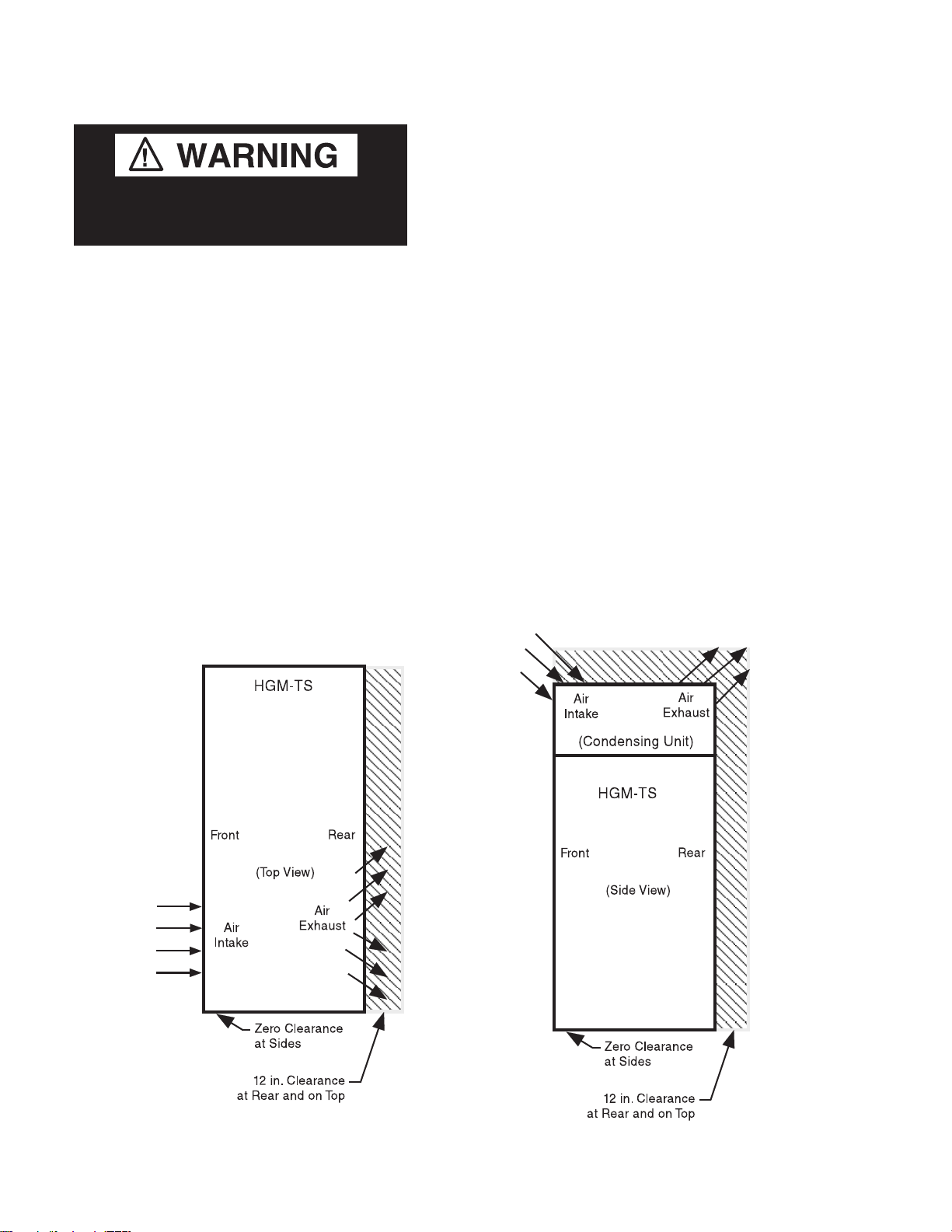
Be sure to position self contained
merchandisers properly.
HGM-TS Location
The condensing unit is located at the top of
the HGM-TS. At least 12 inches of clearance
should be allowed at the rear of the cabinet and
at the top of the merchandiser. This clearance is
necessary to provide free air movement to and
from the condensing unit for maximum
operating efficiency.
P/N 0515297_E U.S. & Canada 1-800-922-1919 • Mexico 1-800-890-2900 • www.hussmann.com
P/N 0515297_E 1-3
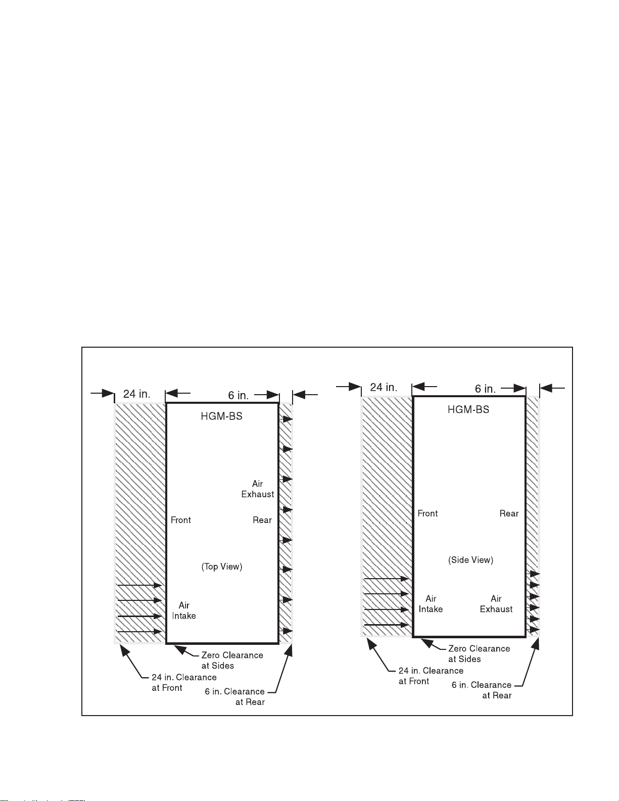
HGM-BS Location
At least 24 inches of clearance should be
maintained in front of HGM-BS merchandisers
and 6 inches of clearance at the rear to provide
the necessary free air movement to and from
the condensing unit. The condensing unit is
located at the bottom of these merchandiser.
HGM-2BS merchandisers require the same
clearance space, but the air flow is different
as shown in the illustration at right. Avoid
installing 1-door merchandisers on the left side
of the case.
HUSSMANN CORPORATION • BRIDGETON, MO 63044-2483 U.S.A.
HGM Merchandisers
1-4 InstallatIon
MODEL DESCRIPTION
The HGM-BS/TS models are self-contained,
medium temperature, vertical glass door
merchandisers designed for the display of dairy
products, deli items and beverages. Design
features include self-closing glass doors,
efficient foamed in place non-CFC insulation
and balanced R-134a refrigeration systems for
energy saving performance.
UNLOADING
Unloading from Trailer:
Lever Bar (also known as a Mule, Johnson
Bar, J-bar, Lever Dolly, or Pry Lever)
Move the merchandiser as close as possible to
its permanent location and remove all packaging.
Check for damage before discarding packaging.
Remove all separately packed accessories such
as kits and shelves.
Improper handling may cause damage to
the merchandiser when unloading. To avoid
damage:
1. Do not drag the merchandiser out of the
trailer. Use a Johnson bar (mule).
2. Use a forklift or dolly to remove the
merchandiser from the trailer.
EXTERIOR LOADING
Do NOT walk on top of merchandisers or
damage to the merchandisers and serious
personal injury could occur.
merchandisers are not structurally
designed to support excessive external
loading such as the weight of a person. Do
not place heavy objects on the merchandiser.
SHIPPING SKID
Each merchandiser is shipped on a skid to
protect the merchandiser’s base, and to make
positioning the case easier.
Remove the top of the crate and detach walls
from each other. Lift crate from the skid.
Unscrew the case from the skid. The fixture
can now be lifted off the crate skid. Lift only at
base of skid! Remove any braces and/or skids
attached (blanket wrapped merchandiser may
have skids).
DO NOT TILT MERCHANDISER ON ITS
SIDE OR END WHEN REMOVING SKID.
Tilting merchandiser could cause damage to
the refrigeration system.
Once the skid is removed, the merchandiser
must be lifted —NOT PUSHED— to reposition.
To remove the skid, remove screws attaching
skid to the merchandiser.
Do not store objects or ammable
materials atop the unit.
Check floor where cases are to be set to see if
it is a level area. Determine the highest part of
the floor.
Unpack door and all packaged accessories.
Do NOT remove shipping crate until the
merchandiser is positioned
for installation.
P/N 0515297_E U.S. & Canada 1-800-922-1919 • Mexico 1-800-890-2900 • www.hussmann.com
P/N 0515297_E 1-5
Drain
(HGL-BS Shown)
MERCHANDISER LEVELING
Be sure to position merchandisers
properly. Level the merchandiser at corners.
Merchandiser(s) must be installed level to
ensure proper operation of the refrigeration
system and to ensure proper drainage of
defrost water. The merchandiser can be leveled
by shimming under the cabinet base frame, or
by installing optional leg levelers.
The self-closing doors require the cabinet to be
properly leveled. End to end leveling will allow
the door(s) to close with uniform speed and
tightness. A slight pitch from front to rear
is desirable.
should never Be higher than the front.
the Back of merchandiser
LEG INSTALLATION (Top Mounts Only)
Install the NSF approved legs after the case is
near its final location. The legs are packaged
inside the cabinet. Replace the tape and door
blocks.
To install legs:
Raise one end of the cabinet about 8 inches.
Block the merchandiser securely, and install
two legs. The leg mounting plates are factory
installed and contain a
1
/2 x 13 in. tapped hole
to mate with the leg assembly. The procedure
is repeated on the opposite end. Three-door
merchandisers require legs in the center.
The cabinet should now be positioned at its
final location with all legs installed. The
merchandiser is leveled by turning the bottom
section of each leg . End to end leveling will
make the door(s) close with uniform speed and
tightness. A slight pitch from front to rear is
desirable.
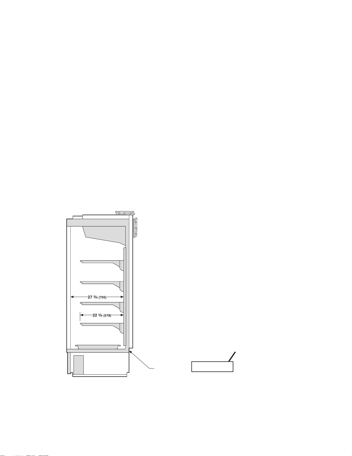
SERIAL PLATE LOCATION
The serial plate is located in the upper lefthand corner of the merchandiser’s interior.
The serial plate contains all pertinent
information such as model, serial number,
amperage rating, refrigerant type and charge.
Do not remove the serial plate under any
circumstance.
Serial Plate
HUSSMANN CORPORATION • BRIDGETON, MO 63044-2483 U.S.A.
HGM Merchandisers
1-6 InstallatIon
REFRIGERATION UNIT ACCESS
Top Mounts — The top decorative panel is
removed by lifting the panel up and pulling
forward.
Bottom Mounts — The lower front panel may
be removed by removing screw at bottom and
lifting the panel straight upward and over
the tabs on which it is hanging. The panel is
installed by reversing the above procedure.
Then
Lift up and
out to remove
access panel
First
Ensure lower front panel is flat against the
floor when installed to prevent air circulation
problems for self contained merchandisers.
If the condensing unit needs to be serviced, it
can be pulled out to gain access for hard to
reach components like the condenser fans.
To pull out the condensing unit, remove the
two hold down brackets at the unit base.
Care must be given to the drain line when
replacing the condensing unit into the case.
The drain line must be inside the defrost water
evaporation pan to prevent the discharge of
water on the floor.
SEALING MERCHANDISER TO FLOOR
(Bottom Mounts Only)
If required by local sanitary codes, or if the
customer desires, merchandisers may be sealed
to the floor using a vinyl cove base trim. The
size needed will depend on how much variation
there is in the floor, from one end of the
merchandiser to the other. Sealing of the lower
front and rear panels on self contained models
may hamper their removal for servicing or
maintenance of the condensing unit.
NOTE: Do not allow trim to cover any intake
or discharge grilles located in the lower front
panel.
AIR DISTRIBUTION & REAR FLUE
SPACER
Air is drawn through the evaporator from
front to rear and is discharged down the back
wall, returning up the face of the glass door to
the return air grille.
NOTE: Rear flue spacer must be in place as
this forms a discharge air flue at the back of
the cabinet.
SHELVES
Each cabinet is provided with four cantilever
shelves per door that are adjustable by 1 inch
increments. The shelves can also be tilted.
Each cabinet has one bottom shelf per door.
These shelves have one-inch legs to allow
proper air flow in the cabinet. Behind the
shelves are wire flues spacers, which allow for
proper air flow. All shelves and flue spacers
are white and epoxy coated for durability and
ease of cleaning. Shelves should be adjusted to
desired operating height. Do not load product
so that it touches the evaporator coil cover.
Do not extend product past the front edge of
the shelf. Extending past the edge will seriously
affect internal air flow through the cabinet.
Shelves are UL rated for a maximum load of
120 lbs.
Do not overloaD the shelves.
P/N 0515297_E U.S. & Canada 1-800-922-1919 • Mexico 1-800-890-2900 • www.hussmann.com
P/N 0515297_E 1-7
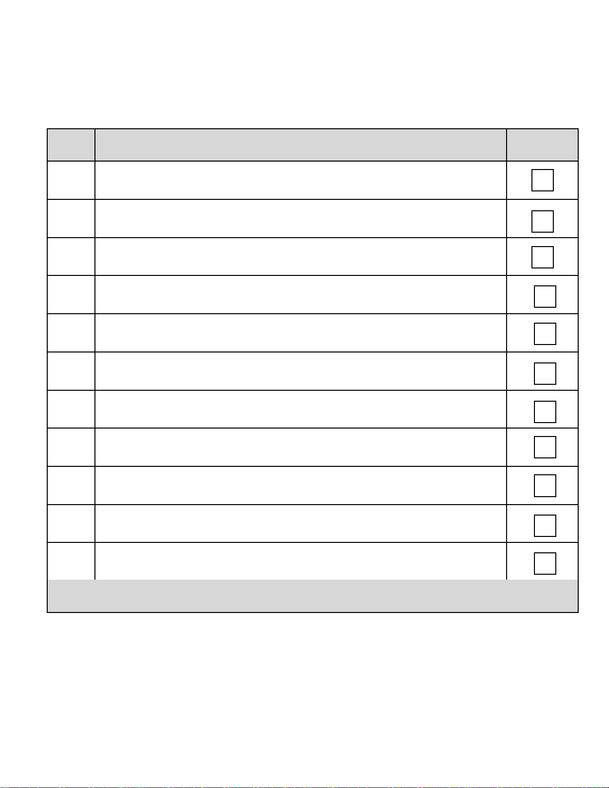
Hussmann Self-Contained Refrigeration Equipment Start Up Check List
***Please note that failure to follow this start-up document may void your factory warranty***
Step Startup Activity Check
1
Locate, read and maintain install/operation manual in a safe place for
future reference.
2 Examine unit. Conrm there is NO damage or concealed damage.
3 Level the unit, side to side and front to rear.
4 Remove all shipping brackets/compressor straps/bolts etc.
5
6
Unit must be run on a dedicated electrical circuit without the use of an
extension cord.
Ensure that the proper electrical requirements for the equipment are
supplied.
7 Verify eld electrical connections are tight.
8
Verify all electrical wiring is secured and clear of any sharp edges or
hot lines.
9 Verify the condensate drain line is properly trapped and pitched.
10 Verify all required clearances on the sides and back of unit.
11
Verify there are no air disturbances external to the unit. Heat and air
registers, fans, and doors etc.
Advise owner/operator that merchandiser must operate at temperature for 24 hrs prior to
loading with product.
Form HSCW01 Rev. 30MAY12 P/N 0525209_B
LEGAL DISCLAIMER:
Hussmann shall not be liable for any repair or replacements made without the written consent of Hussmann, or when the product is installed or operated in a
manner contrary to the printed instructions covering installation and service which accompanied such product.
HUSSMANN CORPORATION • BRIDGETON, MO 63044-2483 U.S.A.
HGM Merchandisers

1-8 InstallatIon
P/N 0515297_E U.S. & Canada 1-800-922-1919 • Mexico 1-800-890-2900 • www.hussmann.com
P/N 0515297_E 2-1
ELECTRICAL / REFRIGERATION
MERCHANDISER ELECTRICAL DATA
Refer to Appendix A of this manual or the
merchandiser’s serial plate for electrical
information.
FIELD WIRING
Field wiring must be sized for component
amperes stamped on the serial plate. Actual
ampere draw may be less than specified.
ALWAYS CHECK THE SERIAL PLATE FOR
COMPONENT AMPERES
ELECTRICAL CONNECTIONS
All wiring must be in compliance with NEC
and local codes. All electrical connections (for
the HGM remote models) are to be made in
the electrical Handy Box located behind the
removable base panel at the right end of the
merchandiser when facing the discharge
honeycomb. The cabinet supply breakers
should be disconnected before removing the
enclosure cover.
The wall circuit must be dedicated for the
merchandiser. Failure to do so voids the
warranty. Do not use an extension cord. Never
plug in more than one merchandiser per
electrical circuit.
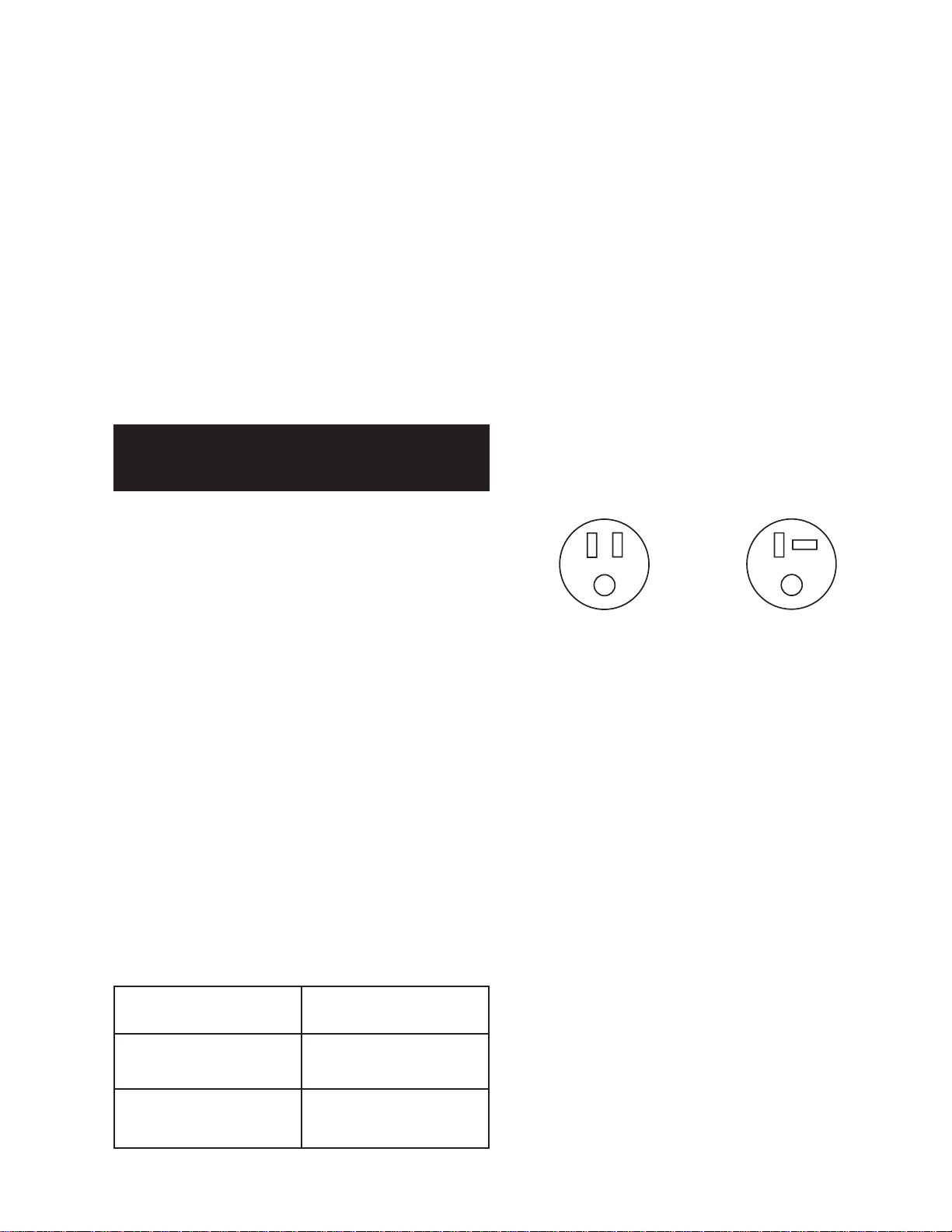
• Always use a dedicated circuit with the
amperage stated on the unit.
• Plug into an outlet designed for the plug.
• Do not overload the circuit
• Do not use long or thin extension cords.
Never use adapters.
• If in doubt, call an electrician.
NEMA 5-15P
HGM-1, 2 BS/TS
All HGM models are supplied with a power cord
and grounding prong for operation on a 115V
power supply.
NEMA 5-20P
HGM-3 BS/TS
REFRIGERATION
ELECTRICAL OUTLET:
Before the merchandiser is connected to any
wall circuit, use a voltmeter to check that the
outlet is within the recommended voltage
limits:
Nominal Volts 120V
Minimum Volts 108V
Maximum Volts 132V
HUSSMANN CORPORATION • BRIDGETON, MO 63044-2483 U.S.A.
(Self Contained Models)
Each self contained model is equipped with
its own condensing unit and control panel
located beneath the display area. The correct
type of refrigerant will be stamped on each
merchandiser’s serial plate. The merchandiser refrigeration piping is leak tested. The
unit is charged with refrigerant, and shipped
from the factory with all service valves open.
HGM Merchandisers
2-2 InstallatIon
Risk of Electric Shock. If cord or plug
becomes damaged, replace only with
a cord and plug of the same type.
Refrigeration lines are under pressure.
Refrigerant must be recovered before
attempting any connection or repair.
WATER OUTLET AND WATER SEAL
Merchandiser must be grounded.
Do not remove the power supply cord ground.
LINE SIZING
(Remote Models)
Refrigerant line connections are made at
the right end of merchandiser (facing front)
beneath the refrigerated display area. The
refrigerant line connection size is
suction line is
5
/8 in. Refrigerant lines should
3
/8 in. The
be sized as shown on the refrigeration legend
that is furnished for the store or according to
ASHRAE guidelines.
Oil Traps
P-traps (oil traps) must be installed at the base
of all suction line vertical risers.
Pressure Drop
Keep refrigerant line runs as short as possible
to avoid large pressure drops. Use a minimum
number of elbows. Where elbows are required,
use long radius elbows only.
The cabinet is provided with a factory installed
outlet for defrost water. It runs from the
bottom of the display area to an evaporation
pan near the condenser unit.
The outlet is not connected to the waste water
system for washing out the cabinet. This system
is designed to evaporate normal condensate.
This system should be checked regularly, especially during high relative humidity conditions, to
verify the condensate tube is not blocked, and
that the pan does not accumulate too much
water which could spill out on the floor.
— LOCK OUT / TAG OUT —
To avoid serious injury or death from electrical shock, always disconnect the electrical
power at the main disconnect when servicing
or replacing any electrical component. This
includes, but is not limited to, such items as
doors, lights, fans, heaters, and thermostats.
When brazing pipes, be sure to use the
insulation blanket shipped with the
Product will be degraded and may spoil if
allowed to sit in a non-refrigerated area.
merchandiser to prevent damage to the
metal merchandiser bottom.
P/N 0515297_E U.S. & Canada 1-800-922-1919 • Mexico 1-800-890-2900 • www.hussmann.com
P/N 0515297_E 3-1
START UP / OPERATION
START UP
1. Check the cabinet thoroughly for loose
nuts and bolts and electrical connections.
Inspect the refrigeration lines for any vis
able damage or chafing.
2. Replace the electrical box cover.
3. Start the merchandiser and allow the
merchandiser to pull down to operating
temperature.
The merchandiser must operate for 24 hours
before loading product. Regularly check
temperatures. Do not break the cold chain.
Keep products in cooler before loading
merchandiser. These merchandisers are
designed for pre-chilled product only.
OPERATION
Power Switch
The power switch is located at the electrical
box behind the top, decorative panel (TS models)
or bottom louvered panel (BS models). The
switch will shut off all power to the merchandiser.
Light Switch
Each HGM model has a convenient ON/OFF
switch so lights may be turned off to conserve
energy during hours when the store is closed.
The switch only controls the lights.
Product will be degraded and may spoil if allowed to sit
in a non-refrigerated area.
Under normal conditions, after the cabinet is
installed and running, very little maintenance
should be required. Follow the list of instruction below after initial startup and for periodic
maintenance purposes.
1. Check operation of condenser fan motors.
Fan blades must turn freely.
2. Check drain pan and heater to prevent
accidental overflow.
3. Make sure doors are closing properly and
that the gaskets seal.
4. Make sure all evaporator fan motors are
running. These can be seen through the
grille inside the cabinet.
...ATTENTION
INSTALLER
It is the contractor’s responsibility to install
merchandiser(s) in accordance with all local
building and health codes.
HUSSMANN CORPORATION • BRIDGETON, MO 63044-2483 U.S.A.
HGM Merchandisers
3-2 Start up / OperatiOn
Position
START UP / OPERATION
Safe-NET III™
TEMPERATURE AND DEFROST
CONTROLLER
SAFE-NET III™ USER INSTRUCTIONS
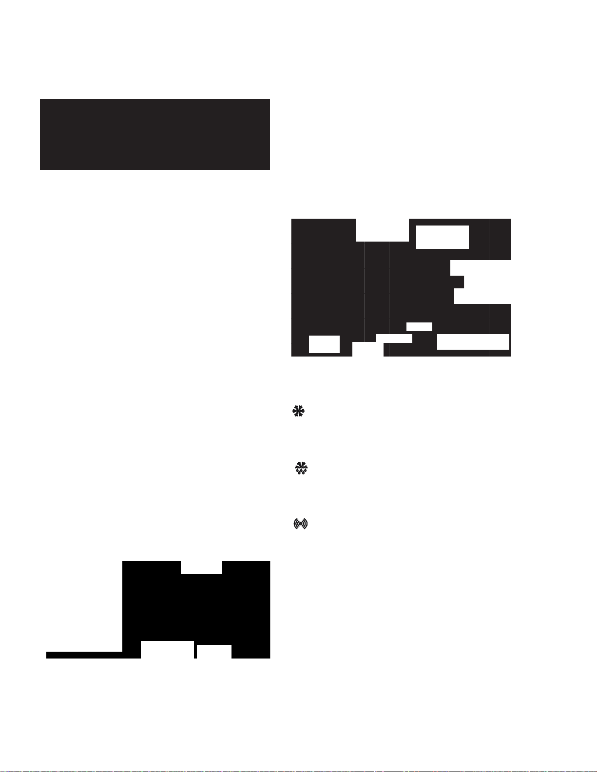
Your refrigerated case uses a Hussmann
Safe-NET™ III temperature and defrost
controller to precisely maintain the temperature and prevent frost buildup on the cooling
coil. LEDs indicate when the compressor or
refrigeration is on, when the case is in a defrost
cycle, if the temperature is outside the desired
range, or if there is a sensor failure.
An adjustment knob allows the temperature
to be set within the configured range and can
power off the controller and compressor. Your
controller has been custom-configured to provide the best temperature and defrost control
for your chilled or frozen food.
The front of the controller has an adjustment
knob and status LEDs. The back of the
controller has connections for sensors and
switched equipment.
Adustment
Knob
Compressor Powered On
green
The Safe-NET III controller includes the
following features and connections.
• Adjustment knob:
Adjusts the temperature setpoint.
Turn adjustment knob to OFF to turn off
refrigeration system. Unplug merchandiser
from power before servicing the unit.
Case
Heater
E72R
Temperature
Fan
E72R only
Sensor
Compressor
Evaporator
Temperature
Sensor
Power
Sensor and Switch
Common
Defrost Termination
Switch (optional)
Interface Box and
Copy Card TTL Connector
• Controller LEDs:
Compressor Powered On LED (green):
Lights while the compressor is running or
the refrigeration valve is open.
Defrost Cycle LED (yellow):
Lights while the refrigeration coil is
defrosting.
Temperature or Sensor Alarm (red):
Lights if the temperature is too warm or
too cold. Flashes if a sensor fails.
Defrost Cycle
yellow
Temperature or Sensor Alarm
red
Warm
Position
Off
Position
Cold
P/N 0515297_E U.S. & Canada 1-800-922-1919 • Mexico 1-800-890-2900 • www.hussmann.com
P/N 0515297_E 3-3
START-UP
• Rear connections:
– Case temperature sensor:
• Typically senses the temperature
of the air in the case.
Used by the controller to determine when
to power on or power off the compressor
or refrigeration.
– Compressor or refrigeration relay:
• Switches on the compressor or
refrigeration valve for cooling.
The optional evaporator fan remains
ON when the adjustment knob is in the
Off position.
Before applying power to the merchandiser,
remove the front grille.
Check thermostat knob is at the appropriate
position. See temperature adjustment on
Page 3-6.
Check the check the merchandiser’s cabinet
thoroughly for loose nuts and bolts. Check all
electrical connections. Inspect the refrigerant
lines for any visible damage or chafing.
Replace the front grille.
The following list of housekeeping practices
will assure trouble-free operation:
• Check operation of condenser fan motors.
Fan blades must turn freely.
DISPLAY
The display includes three red LEDs and two
digits for temperature, defrost status, and error
codes.
The three display LEDs are red, and their
behavior matches the LEDs on the controller.
Compressor
Powered On
Defrost Cycle
Temperature or
Sensor Alarm
• Check drain pan and heater to prevent
accidental overflow.
• Make sure doors are closing properly, and
that gaskets are sealed.
• Make sure all evaporator fan motors are
running. These can be seen through grille
inside of cabinet.
HUSSMANN CORPORATION • BRIDGETON, MO 63044-2483 U.S.A.
HGM Merchandisers

3-4 Start up / OperatiOn
1. Plug in the merchandiser.
The OFF Position does not disconnect line
voltage to the case, refrigeration unit, fan, or
heater.
2. Wait for the self check to complete. During
the self check, each LED flashes for one
second, then all LEDs turn on for two
seconds. If the LEDs do not flash, make
sure the adjustment knob is not in the Off
position.
• After the self check, all LEDs turn off
until the compressor starts. There may be
a delay before the compressor starts. If the
red Temperature or Sensor Alarm LED
stays on after the self check.
• The green Compressor Powered On LED
turns on when the compressor starts.
NOTE: Do NOT load product until AFTER
merchandiser operates for 24 hours and reaches
desired operating temperature.
Safe-NET parameter code is 58.
Product will be degraded and may spoil if allowed to
sit in a non-refrigerated area.
P/N 0515297_E U.S. & Canada 1-800-922-1919 • Mexico 1-800-890-2900 • www.hussmann.com
P/N 0515297_E 3-5
Green
(Refrigeration)
Yellow
(Defrost)
Red
(Alarm)
‘OFF’ Position
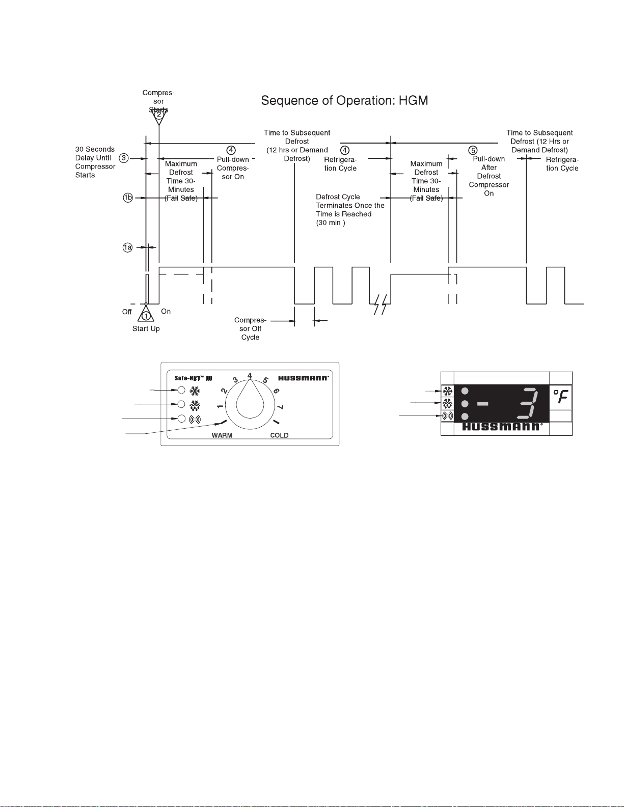
1. During the self check a 2 digit number
will appear for 3 seconds. Then each LED
flashed for one second and then all LED’s
turn on for two seconds. If the LED’s do
not flash, make sure the adjustment knob is
not in the “OFF” position.
2. The compressor will start after a delay; 30
seconds after the power is applied.
3. The compressor will continue to run until it
reaches its cut-out temperature (pull down).
Green
(Refrigeration)
Yellow
(Defrost)
Red
(Alarm)
4. The refrigeration cycle will continue until the
next scheduled defrost (12 hours).
5. The above process will repeat (steps 3 and 4)
until the power is interrupted.
6. If power stops, the process will start over at
Step 1, and the time to subsequent defrost will
reset.
HUSSMANN CORPORATION • BRIDGETON, MO 63044-2483 U.S.A.
HGM Merchandisers
 Loading...