

Hussmann HGM-1BS, HGM-3BS, HGM-2BS, HGM-1TS, HGM-2TS Installation And Service Instructions Manual
...
January 2006
INSTALLATION & SERVICE
INSTRUCTIONS
FOR
HGM-1, 2 & 3 BS,TS SELF-CONTAINED
Medium Temperature Glass Door Merchandiser
First Call for help (US and Canada):
1-800-922-1919
Soporte Tècnico y Asistencia (Mèxico):
01-800-522-1900
For a Service Network Locator and other
Information visit us at
www.hussmann.com
select Worldwide Locations
P/N OII – HGM BS-TS Self-Contained
January 2006
HUSSMANN - GLOVERSVILLE

TABLE OF CONTENTS
Introduction 2
Inspection Upon Receipt – Proper Location and Clearance 2
Skid 2
Leg Installation 2
Leveling and Sealing 3
Condensate Pan 3
Bottom Louvered Panel Removal 3
Top Decorative Panel Removal 3
Shelves 3
Air Distribution and Rear Flue Spacer 3
Serial Plate Information Electrical Connections 4
Electrical, BTU Capacities 4
Initial Start Up and Loading 4
General Upkeep and Cleaning 5
Power Switches, Temperature Controls 5
Thermometer 6
Electrical Enclosure 6
Lighting 6
Refrigeration 7
Leak Testing 7
Evacuation 7
Operational Data and Refrigerant Control 8
Trouble Shooting, and Lights Trouble Shooting 9 & 10
Warranty and Electrical Components Replacement List 11 & 12
Commercial Door Literature 13-16
Page 1

Introduction –
The HGM-BS/TS models are self contained, medium temperature, vertical glass
door merchandisers designed for the display
of dairy products, deli items, beverages, and
wine. Design features include self-closing
glass doors, efficient foamed in place nonCFC insulation, and balanced R-134a refrigeration systems for energy saving performance.
Inspection upon receipt –
Upon receipt of the cabinet, carefully
examine the crating for damage. If crate is
damaged, make a note on the delivery ticket
before signing. Carefully remove shipping
crate and examine cabinet for “concealed”
damage. If damage is found, contact the delivery carrier immediately and have his agent
prepare an inspection report for the purpose
of filing a claim. THIS IS YOUR RESPONSIBILITY.
Proper Location & Clearance –
allowed in front of the case and six (6) inches of
clearance at the rear to provide the necessary
free air movement to and from the condenser.
INITIAL SET-UP Skid –
The skid should be left on the case until it
is near its final location. The skid provides protection for both case and floor. The skid is removed by raising one end of the case approximately six inches. Block securely and remove
the two skid bolts on the raised end. The procedure is repeated on the opposite end. When the
skid bolts are removed, the case may be slid off
the skid.
Leg Installation – Top Mounts only
After the case is near its final location
and the skid has been removed, the NSF approved legs should b e installed. The legs are
packaged inside the cabinet. Replace the tape
and door blocks. To install legs, raise one end of
the cabinet approximately eight (8) inches, block
securely, and install two legs.
Avoid locating the cabinet where direct
sunlight would shine into the fixture or where
drafts from air conditioning grills, fans and
open doors could affect its operation.
Because the condensing unit is located
at the top of the HGM-TS, at least twelve (12)
inches of clearance should be allowed at the
rear of the cabinet and at the top of the case.
This clearance is necessary to provide free air
movement to and from the condenser for
maximum operating efficiency.
Because the condensing unit is located
on the bottom of the HGM-BS, at least twenty
four (24) inches of clearance should be
Page 2
The leg mounting plates are factory installed and contain a ½ x 13 tapped hole to mate
with the leg assembly. The procedure is repeated on the opposite end. The 3-door requires
legs in the center. With cabinet legs installed,
the cabinet should be positioned in its final location and leveled.
The cabinet is leveled by turning the bottom section of each leg. The self-closing doors require
the cabinet to be properly leveled. End to end
leveling will make the door (s) close with uniform speed and tightness. A slight pitch from
front to rear is desirable.
THE CABINET BACK SHOULD
NEVER BE HIGHER THAN THE FRONT.
electrical box to allow the electrical box to
slide out for servicing.
Leveling and Sealing
– Bottom
Mounts only
The case can be leveled by shimming under the cabinet base frame, or be installing optional levelers. The self-closing doors require
the cabinet to be properly leveled. End to end
leveling will make the door (s) close with uniform speed and tightness. A slight pitch from
front to rear is desirable.
Silicone Sealant
Condensate Pan –
Floor
An electrically heated (300w, 115v) condensate pan is provided to evaporate the defrost
water. The heated condensate pan slides onto
the slide plate on the cabinet bottom on TS
cases and has a thermistor. On BS cases the
pan is screwed to the base of the case. The pan
is removable for cleaning. A vinyl drain tube is
provided for connection to the heated condensate pan. The drain must be trapped to guard
against drain line freezing and for good sanitation practice.
Bottom Louvered Panel Removal –
The louvered panel provides access to
the condensing unit and the electrical box.
Remove panel by removing the shipping
screw (s) at bottom and lifting up and pulling
forward. Remove shipping screw on
Top Decorative Panel Removal –
The top decorative panel is removed by
lifting up and pulling forward.
Shelves
–
Each cabinet is provided with 4 cantilever shelves per door that are adjustable on 1inch increments and are tiltable. Each cabinet
also has one bottom shelf per door. These
shelves have one-inch legs to allow proper airflow in the cabinet. Behind the shelves are
wire flue spacers which also allow for proper
airflow. All shelves and flue spacers are white,
epoxy coated for durability and ease of cleaning. Shelves should be adjusted to desired operating height.
When loading product, into the cabinet,
care should be taken not to load product so
that it touches the evaporator coil cover. Do
not extend product past the front edge of the
shelf. Extending past the edge will seriously
effect internal air flow through out the cabinet.
Shelves are UL rated for a maximum
load of 123 lbs. DO NOT OVERLOAD
SHELVES.
Air Distribution and
Rear Flue Spacer –
Air is drawn through the evaporator
from front to rear and is discharged down the
back wall, returning up the face of the glass
door to the return air grill. NOTE: Rear flue
Page 3

spacer must be in place as this forms a discharge air flue at the back of the cabinet.
Electrical Connections –
The HGM-1 and 2 cases are supplied
with a supply cord as charted below with a
grounding prong for operation on a 115v power
supply. Do not remove the grounding prong
under any circumstances. The HGM-3 requires
hard wiring to a 30 amp, 115v circuit.
Cord Plug Nema
Model Amperage Designation
HGM-1-BS/TS 15 5 – 15 P
HGM-2-BS/TS 20 5 – 20 P
Serial Plate Information –
The serial plate is located in the upper
left-hand corner of the case interior. It has all
the pertinent information needed for proper
electrical installation. The serial plate should
not be removed for any reason.
NOTE: Connecting this unit to any electrical
supply other than specified on the serial plate
will void the warranty and may result in serious
damage with its own service.
Electrical –
Unit Run Ship
H.P. Hz/Ph Volts Amps Fuse Size Wt.
1-BS 1/3 60/1 115
2-BS 1/2 60/1 115 12.5 20 amp 825
3-BS 3/4 60/1 115 20.5 30 amp 1096
1-TS 1/3 60/1 115
2-TS 1/2 60/1 115 12.5 20 amp 776
3-TS 3/4 60/1 115 20.5 30 amp 1050
BTU Capacities –
Rating Temps ºF
BTU/HR EVAP COND AMB
1-TS/BS 2300 +25 110 90
2-TS/BS 2570 +25 110 90
3-TS/BS 3620 +25 110 90
The HGM cases use R-134a refrigerant. Check the serial plate for the specific refrigerant
charge used.
Page 4

Initial Start-up and Loading –
Check the cabinet thoroughly for loose nuts
and bolts and electrical connections. Inspect the refrigeration lines for any visible
damage or chafing.
Replace the electrical box cover.
Start the cabinet and allow to pull down to
operating temperature before loading.
General Upkeep and Cleaning –
1. To insure good sanitation, appearance, and
minimum maintenance, the cabinet should
be cleaned and washed regularly as sue demands. Clean with mile detergent and
warm water. DO NOT USE AN ABRASIVE CLEANER OR STEEL WOOL AS
THEN WILL MAR THE FINISH.
1. Under normal conditions, after the cabinet
is installed and running, very little maintenance should be required. However, the following list of housekeeping practices will
assure trouble-free operation.
a) Check operation of condenser fan motors.
Fan blades must turn freely.
a) Check drain pan and heater to prevent acci-
dental overflow.
a) Make sure doors are closing properly and
that the gaskets seal.
a) Make sure all evaporator fan motors are
running. These can be seen through grill
inside cabinet.
a) Clean the cabinet with a mild detergent.
this will insure good sanitation, and minimize maintenance. Never use an abrasive as
this could mar the finish.
a) A regular program should be set up for the
cleaning of the fin-and-tube condenser.
Normally, this cleaning is required every 3
to 4 months, but the individual store application may shorten or lengthen this time period. Dust and dirt accumulation can cause
serious efficiency loss.
a) On the BS cases (bottom mounts) access is
gained to the unit area by removing the louvered grille. The unit slides forward to facilitate cleaning and for service. Care
should be taken when pushing the unit back
in place to insure that the pullout coil does
not become kinked or damaged in some
way.
OPERATION AND MAINTENANCE
Power Switches –
The power switch is located at the electrical box which is behind the top decorative
panel (TS models) or bottom louvered panel
(BS models). The switch will shut off al power
to the case.
Temperature Control –
The electrical temperature control is located in
the electrical box. The temperature control
does not have an ‘OFF’ position.
Adjustments may be made by turning
the knob on the face of the dial. Turning it
clockwise will give warmer temperatures while
counter-clockwise will give colder temperatures.
Page 5

There is also and adjustable temperature differential (the difference between the cutin temperature and the cut-out temperature)
located on the back of the temperature control
cover. When adjusting the differential, the temperature setting may also have to be adjusted.
See figure below for internal adjustment locations.
The control has a range of –20º F to
+220º F with a differential of 1º to 30º. It is factory set for approximately 29ºF with a 10º differential. The temperature should be checked
with a thermometer other than the case thermometer after it is running to insure that the
case is running at the proper temperature for
the product.
A picture of A319 Electronic Temperature Control and Board Layout is located on
the last page of this booklet.
Thermometer –
The thermometer is located by looking
through the right hand door onto the right
hand end of the fan plenum.
The thermometer will also warm up
rather rapidly when the case door is held open
for a time such as when the case is being restocked or a shopper is making a decision on a
product. After the door is closed it will take
some time for the thermometer to pull back
down to the case temperature. The thermometer and temperature control sense discharge air
temperature which is 5-10º colder than the case
temperature.
The thermometer may be replaced by
removing the two screws securing it to the
evaporator fan grill. Lower the evaporator coil
cover by removing the brass thumb screws
located at each end of the cover, and backing
out the thumb screws located along the front
edge of the cover.
Follow the sensing lead from the thermometer until you locate the sensing element.
Loosen the clamp securing the element and remove the element. Remove the thermometer.
Assemble is the reverse order making sure you
first thread the element through the hole in the
evaporator fan grill. Cleaning of the sensing
element may also be accomplished in this manner.
Electrical Enclosure –
For servicing convenience, access is
gained by removing the access panel and electrical box cover. The cabinet supply breakers
should be disconnected before removing the enclosure cover.
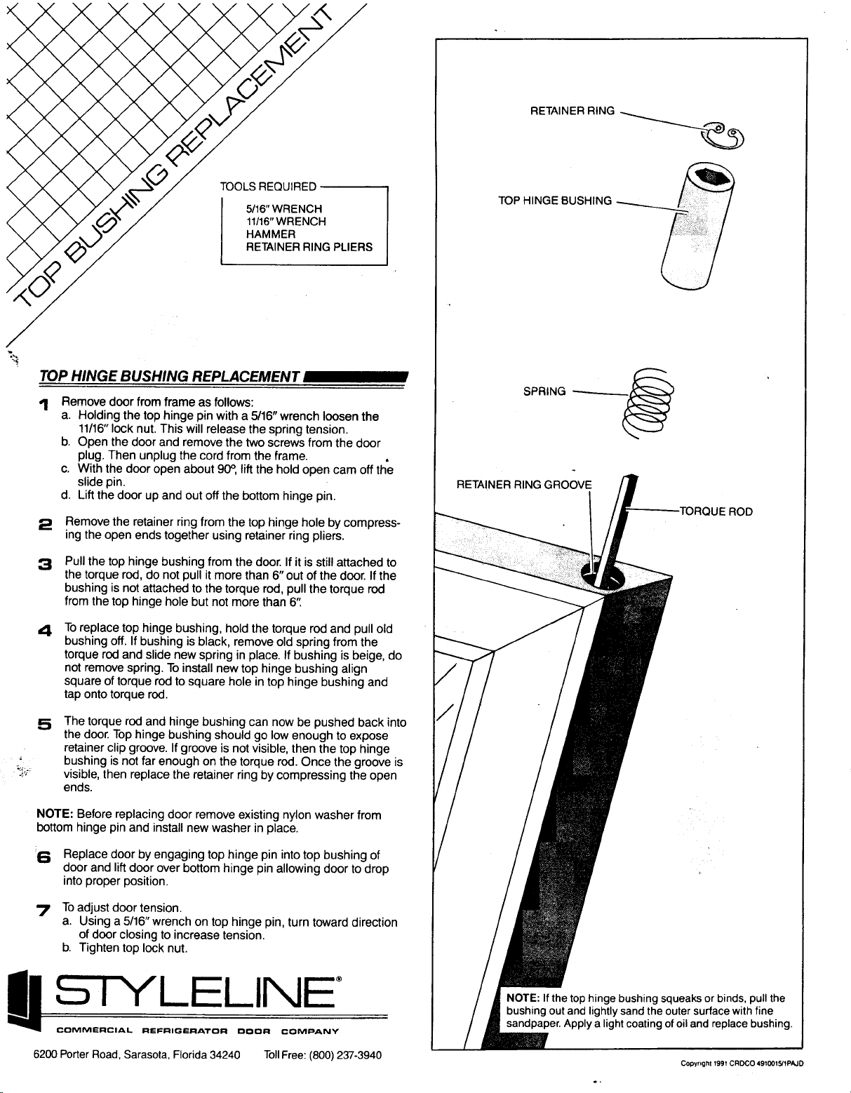
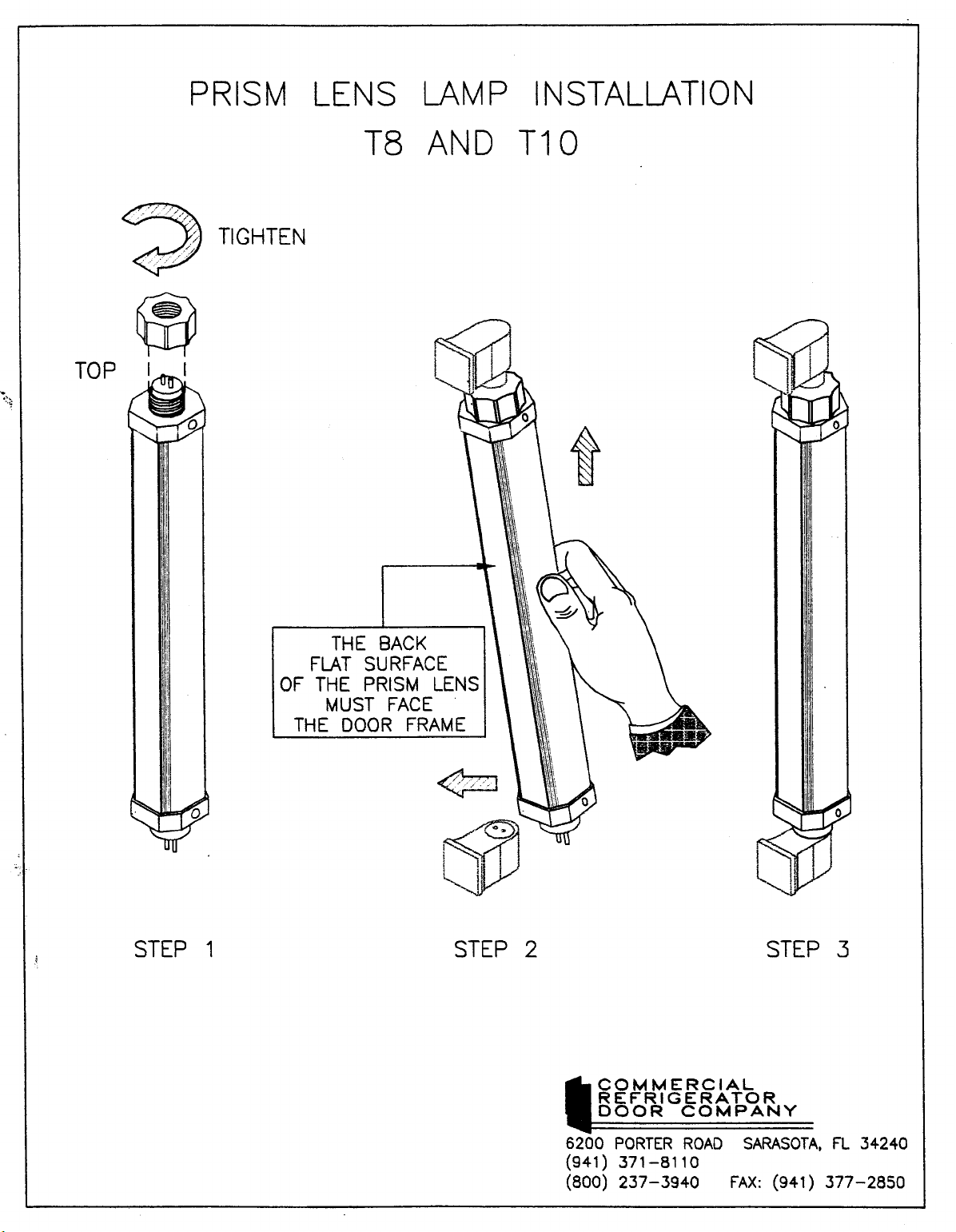
Lighting –
Electronically powered T-8 lamps located inside each doorway provide interior
lighting. The tubes are enclosed in a patented
lens system to maintain proper heat around the
bulb for maximum light intensity and to protect
the product in case of breakage. See the
Commercial instructions for the lens removal,
attached at the back of this booklet.
Each HGM model has a convenient ON/
OFF switch so lights may be turned off to conserve energy during hours when the store is
closed. The switch is located inside the cabinet
above the left hand door. This switch only controls the lights. 115 volt power must be shut off
at the main power supply source located within
the store prior to starting any service or maintenance work.
Page 6

Light ballasts are located on mullions of
the door frames. See the Anthony ballast removal instructions at the back of the booklet.
–
Commercial Doors –
See Door Instructions at
the back of this booklet.
Refrigeration –
As stated previously, these cases are selfcontained with the condensing unit mounted at
the top or bottom. they are equipped with a
hermetic compressor and a capillary tube. The
condenser is of fin and tube construction and
should be periodically cleaned to maintain efficient operation.
If it should become necessary to leak test
the system, please adhere following notice:
NOTICE
considerations being taken today, we ask that
leak testing be done with refrigerant 22 mixed
with nitrogen. If the condensing unit nameplate
designates a refrigerant other than R-22 remove all R-22 from the immediate area to avoid
confusion after leak testing and evacuating the
unit. Recharge the unit with proper refrigerant.
Leak Testing
The test gas cylinder must be equipped
– Because of the CFC atmoshperic
- CAUTION
with a pressure gauge and regulators so that
system test pressures do not exceed maximum
allowable limits. Do not ever use anything
other than an R-22/Nitrogen mixture for leak
testing.
Attach a refrigerant test gas cylinder to
your service manifold and connect the manifold
to the charging port on the liquid line valve.
Charge an R-22/Nitrogen mixture into the system, raising the pressure to the remote unit’s
nameplate for the low side and high side pressures. Using the electronic detector, carefully
check the entire system for leaks. Take special
care to inspect all brazed and flare connections.
Evacuation –
After the system is proven leak tight,
thoroughly evacuate the system according to
the following procedure:
Discharge the refrigerant-nitrogen mixture,
allowing it to blow from the system as rapidly as possible, into an empty cylinder. Be
sure that all service valves and solenoid
valves are open to allow all of the mixture to
be discharged.
Connect a deep-drain vacuum pump to both
the high and low side of the system. Pull a
vacuum on the system to at least 1500 micorns.
Break the vacuum by adding refrigerant
into the system until the pressure is above 0
psig. Always charge the refrigerant line into
the system through a new drier in the charging manifold line. A 16 cubic inch drier is
sufficient for this purpose.
Page 7

Repeat steps 2 and 3 two more times, the
third time evacuating the system 500 microns.
Operational Data
–
The following is typical data for HGM
models based on lab tests, and may vary under
field operating conditions.
Ambient Temperatue
Head Pressure (psi) 120-135
Suction Pressure (psi) 9-12
75ºF
Refrigerant Control
Refrigerant flow to the evaporator is controlled through the use of a capillary tube.
Because the suction line capillary tube assembly (sometimes referred to as heat exchanger
or pull-out coil) has no moving parts, it very
rarely if ever, needs servicing. However, should a
leak occur in the system, it is possible that dirt,
dust, or moisture may collect in the capillary tube
causing the system to go into a vacuum. Should
this occur, it is recommended that dry nitrogen
or a dry refrigerant be forced through the system
to clear the blockage.
If attempts to clear the restriction by this
method are unsuccessful, the entire assembly, not
the capillary tube only, should be replaced with a
new factory ordered replacement.
Page 8

TROUBLE SHOOTING
Symptom Probable Cause (s) Possible Solution (s)
Compressor runs continuously
Product too warm
1. Short of refrigerant 1. Leak check, change drier,
evacuate, and recharge
2. Inefficient compressor 2. Replace
3. Dirty condenser 3. Clean
High Head Pressure 1. Cabinet location too warm 1. Relocate cabinet
2. Restricted condenser air flow 2. Clean condenser to remove
air flow restriction
3. Defective condenser fan mo-
3. Replace
tor
Warm storage temperatures 1. Temperature control not set
4. Air or non-condensable gases
in system
4. Leak check, change drier,
evacuate, and recharge
1. Reset control
properly
2. Short of refrigerant 2. Leak check , change drier,
evacuate, and recharge
3. Cabinet location too warm 3. Relocate
4. Too much refrigerant 4. Change drier, evacuate, and
recharge
5. Low voltage. Compressor
5. Check power
cycling on overload
6. Condenser dirty 6. Clean
Compressor runs continuously
1. Defective control 1. Replace
product too cold
Compressor will not start no
2. Short on refrigerant 2. Leak check, change drier,
1. Blown fuse or breaker 1. Replace fuse or reset breaker
noise
2. Defective or broken wiring 2. Repair or replace
3. Defective overload 3. Replace
4. Defective temperature control 4. Replace
5. Power Control 5. Check service cord or wiring
Page 9
evacuate, and recharge
conditions

TROUBLE SHOOTING CON’T
Symptom Probable Cause (s) Possible Solution (s)
Compressor will not start
cuts out on overload
1. Low voltage 1. Contact electrician
2. Defective compressor 2. Replace
3. Defective relay 3. Replace
4. Restriction or moisture 4. Leak check, replace drier,
evacuate and recharge
5. Inadequate air over con-
5. Clean condenser
denser
6. Defective condenser fan
6. Replace
motor
Trouble Shooting Lighting System
Problem Solution
Light’s won’t start 1. Check light switch
2. Check continuity to ballast
3. Check to see if bulbs inserted properly into
socket
4. Check voltage
Light’s flicker 1. Allow lamps to warm up
2. Check lamp shield for cracks
3. Check sockets for moisture and proper
contact
4. Bulb replacement may be necessary
5. Check voltage
6. New bulbs tend to flicker until used
Ballast hums 1. Check voltage
2. Replace ballast
This HGM case was manufactured in Gloversville, New York. Our phone #’s are (518) 7250644 for NY state residents, and toll free 800-753-7790 or outside NY. Any questions not
covered in this manual, please call the factory.
Page 10

WARRANTY PARTS PROCEDURE, COMPRESSOR REPLACEMENT,
AND
ELECTRICAL COMPONENTS REPLACEMENT LIST
Ordering Replacement Parts –
Contact your nearest Hussmann Distributor
Always specify model and serial number of cabinet
If correct part number is not know, give a clear description of part itself and its func-
tion in the cabinet or remote unit.
Warranty Parts Procedure
Same as above
Give original installation date of cabinet and, if possible, forward a copy of the original
invoice or delivery receipt.
All shipments of in-warranty replacement parts will be invoiced from the factory until
such time as the defective part is returned and proved to be defective by our Quality
control Department.
Contact your Hussmann Distributor for instructions on returning in-warranty parts.
In case of a compressor failure, see next section.
Warranty parts must be returned to the factory within 30 days of date of failure to as-
sure proper disposition.
Lack of any of the above information may result in the shipment of the wrong part, or
a delay in shipment.
Compressor Replacement Procedure
–
Replacement compressors will not be shipped from the Hussmann Factory. They may
be obtained from your nearest Wholesaler.
Your wholesaler will replace, free of charge, any compressor found to be defective
within twelve months of installation, not to exceed twenty months from the date of
manufacture, as determined by the compressor serial number on the serial plate.
Page 11

To obtain reimbursement forward to: Hussmann Corporation
140 East State Street
Gloversville, NY
12078
the following information:
1. The cabinet model and serial number
2. A copy of the wholesaler’s invoice, along with tag from old compressor.
Electrical Components Replacement List
Model HGM-1-TS/BS HGM-2-TS/BS HGM-3-TS/BS
Compressor Tecum. AE44484 Tecum. AKYY60Y Cope. RSL4CIE-IAA
Cond. Fan Mtr. EMS ESPL25EM1 EMS ESPL25EM1
Evap Fan Mtr Bomax 310-5734 same same
Light Ballast Huss. # 6-S-166 same same
Fluores. Lamp F040W-T8-60" same same
Page 12


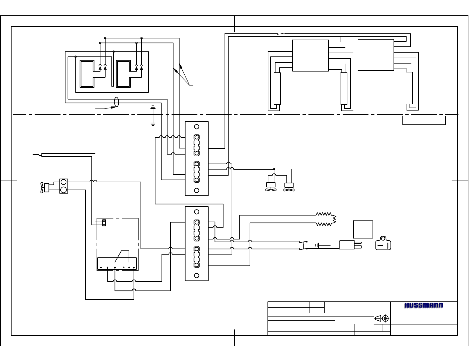
DOOR & FRAME HEATERS
FRAME HEATERS
BLK
WHT
BLK
WHT
DOOR HEATERS
BLU
BLU/WHT
LIGHT SWITCH
LAMP
ORN
ORN
BRN
BRN
BLK
3
WHT
4
8
BALLAST
9
10
1
RED
2
RED
5
BLU
6
BLU
7
LAMP
SENSING
BULB
2
1
COMPRESSOR
WHT
SENSOR
BLK
JUMPER
COMM
240 AC 120 NC C NO
WHT
BLK
PUR
GRD
3-S-226
1 2
3 4
5 6
7 8
9 10
11 12
23 24
25 26
ELEC-TRON
3-S-226
1 2
3 4
5 6
7 8
9 10
11 12
23 24
25 26
ELEC-TRON
BLK
EVAP FANS
BLK
BLK
BLK
WHT
S3
S4
REV EO # REV DATE REV BY
APPROVED BY
-
-
-
-
-
-
--
-
CONDENSATE PAN HEATER
BLK
S1
GRD
WHT
S2
TOLERANCES UNLESS OTHERWISE SPECIFIED: FRACTIONAL 1/32"
DECIMAL 0.031" ANGULAR 1° HOLE LOCATION & SPACING 1/64"
EO NUMBER
DRAWN BY:
DATE DRAWN :
APPROVED BY:
115 V
60 Hz
15 AMP
POWER PLUG
-
-
1 PH
JWL
1/29/96
ANTHONY FRAME
HGM-1-BS
SCALE
INCHES
SHEET #
1 OF 1
PLUG
END
DETAIL
GLOVERSVILLE, NY 12078
WIRING DIAGRAM
M100-2021

DOOR AND FRAME HEATERS
LIGHT
SWITCH
BLU
BLU/WHT
ANTHONY T8 ELECTRONIC LIGHTING
SENSING
BULB
CONDENSOR
FANS
1
C
COMPRESSOR
FRAME HEATERS
WHT
PUR
BLK
WHT
WHT
GRN
DOOR
HEATERS
BLK
WHT
BLK
WHT
BLK
1 2
3 4
5 6
7 8
9 10
11 12
23 24
25 26
BLU
BLU
BLK
3
WHT
ORN
8
BALLAST
ORN
9
ORN/BLK
10
ORN/BLK
BLU/WHT
BLU/WHT
1
LAMP
4
RED
2
RED
5
BLU
BLU
LAMP
ORN/BLK
ORN/BLK
LAMP
ORN
ORN
8
9
10
1
BALLAST
BLK
3
WHT
4
RED
2
RED
5
BLU
66
BLU
77
LAMP
ANTHONY FRAME
BLK
EVAPORATOR FANS
BLK
SENSOR
1 2
3 4
5 6
BLK
COMM
120
240
AC
NOCNC
PUR
WHT
BLK
7 8
9 10
11 12
23 24
25 26
BLK
WHT
S4
BLK
S3
REV EO # REV DATE REV BY
-
APPROVED BY
-
-
-
-
-
WHT
S2
GRN
BLK
S1
--
-
1 PH
60 Hz
115 V
25 AMP
CONDENSATE
PAN
HEATER
TOLERANCES UNLESS OTHERWISE SPECIFIED: FRACTIONAL 1/32"
DECIMAL 0.031" ANGULAR 1° HOLE LOCATION & SPACING 1/64"
EO NUMBER
DRAWN BY:
DATE DRAWN :
APPROVED BY:
-
JLS
SCALE
INCHES
SHEET #
12/01/03
-
1 OF 1
HGM-3-BS
GLOVERSVILLE, NY 12078
WIRING DIAGRAM
M100-2023

DOOR AND FRAME HEATERS
LIGHT
SWITCH
BLU
BLU/WHT
ANTHONY T8 ELECTRONIC LIGHTING
SENSING
BULB
CONDENSOR
FANS
1
C
COMPRESSOR
FRAME HEATERS
WHT
PUR
BLK
WHT
WHT
GRN
DOOR
HEATERS
BLK
BLK
WHT
ORN/BLK
ORN/BLK
ORN
ORN
8
9
10
1
BALLAST
BLK
3
WHT
4
RED
2
RED
5
BLU
6
BLU
7
BALLAST
BLK
3
WHT
4
RED
2
RED
5
BLU
6
BLU
7
BLU
BLU/WHT
LAMP
BLK
WHT
BLU
BLU/WHT
LAMP
LAMP
DOOR FRAME
1 2
3 4
5 6
7 8
9 10
11 12
23 24
25 26
BLK
EVAPORATOR FANS
SENSOR
BLK
BLK
CONDENSATE
PAN HEATER
BLK
COMM
120
240
AC
BLK
WHT
PUR
NOCNC
WHT
BLK
S4
S3
WHT
S2
BLK
S1
REV EO # REV DATE REV BY
-
APPROVED BY
-
-
-
-
-
-
1 PH
60 Hz
115 V
GRN
25 AMP
TOLERANCES UNLESS OTHERWISE SPECIFIED: FRACTIONAL 1/32"
--
DECIMAL 0.031" ANGULAR 1° HOLE LOCATION & SPACING 1/64"
EO NUMBER
DRAWN BY:
DATE DRAWN :
APPROVED BY:
HGM-2-TS
GLOVERSVILLE, NY 12078
-
JLS
SCALE
INCHES
SHEET #
12/01/03
-
1 OF 1
WIRING DIAGRAM
M100-2028
SENSING
BULB
FRAME HEATERS
2
1
COMPRESSOR
DOOR & FRAME HEATERS
BLK
WHT
WHT
SENSOR
BLK
JUMPER
COMM
240 AC 120 NC C NO
WHT
BLK
PUR
GRD
DOOR HEATERS
BLU
BLU/WHT
LIGHT SWITCH
ORN
ORN
BRN
BRN
8
9
10
1
ANTHONY T8 ELECTRONIC LIGHTING
BLK
3
WHT
4
BALLAST
RED
2
RED
5
BLU
6
BLU
7
LAMP
BLK
3
WHT
4
8
BALLAST
9
10
1
RED
2
RED
5
BLU
6
BLU
7
LAMP
LAMP
BLK
WHT
BLK
WHT
ANTHONY FRAME
3-S-226
1 2
3 4
5 6
7 8
9 10
11 12
23 24
25 26
ELEC-TRON
EVAP FANS
BLK
3-S-226
1 2
3 4
5 6
7 8
9 10
11 12
23 24
25 26
BLK
WHT
BLK
CONDENSATE PAN HEATER
S1
S3
S4
S2
BLK
GRD
WHT
20 AMP
POWER PLUG
115 V
60 Hz
1 PH
PLUG
END
DETAIL
ELEC-TRON
HGM-2-BS
REV EO # REV DATE REV BY
APPROVED BY
-
-
-
-
-
-
--
-
TOLERANCES UNLESS OTHERWISE SPECIFIED: FRACTIONAL 1/32"
DECIMAL 0.031" ANGULAR 1° HOLE LOCATION & SPACING 1/64"
EO NUMBER
DRAWN BY:
DATE DRAWN :
APPROVED BY:
-
JWL
SCALE
INCHES
SHEET #
1/29/96
-
1 OF 1
GLOVERSVILLE, NY 12078
WIRING DIAGRAM
M100-2022

DOOR & FRAME HEATERS
LIGHT SWITCH
BLU
BLU/WHT
BRN/BLK
BRN/BLK
ANTHONY T8 ELECTRONIC LIGHT ING
BLK
3
WHT
ORN
8
BALLAST
ORN
9
10
1
4
RED
2
RED
5
RED
6
RED
7
FRAME HEATERS
SENSING
BULB
COMPRESSOR
COND
FAN
LAMP
ANTHONY FRAME
BLK
WHT
DOOR
HEATERS
BLK
WHT
BLK
WHT
LAMP
3-S-226
1 2
3 4
5 6
7 8
2
1
WHT
9 10
11 12
23 24
25 26
BLK
ELEC-TRON
EVAP
FANS
BLK
SENSOR
BLK
CONDENSATE
PAN
HEATER
BLK
COMM
240 AC 120 NC C NO
PUR
WHT
BLK
S2
S4
S3
S1
WHT
BLK
REV EO # REV DATE REV BY
APPROVED BY
-
-
-
-
-
115 V
60 Hz
1 PH
GRD
PLUG END
DETAIL
TOLERANCES UNLESS OTHERWISE SPECIFIED: FRACTIONAL 1/32"
-
-
DECIMAL 0.031" ANGULAR 1° HOLE LOCATION & SPACING 1/64"
--
EO NUMBER
-
DRAWN BY:
DATE DRAWN:
APPROVED BY
JHB
12/1/98
-
UNIT
SHEET #
INCHES
1 OF 1
HGM-1-TS
GLOVERSVILLE, NY 12078
WIRING DIAGRAM
M100-2027

DOOR & FRAME HEATERS
LIGHT SWITCH
ANTHONY T8 ELECTRONIC LIGHT ING
FRAME HEATERS
SENSING
BULB
COMPRESSOR
COND
FANS
BLK
WHT
BLK
3
WHT
ORN
8
BALLAST
ORN
9
BRN/BLK
BLU
BLU/WHT
DOOR
HEATERS
BLK
WHT
BLK
WHT
BRN/BLK
LAMP
10
1
4
RED
2
RED
5
RED
6
RED
7
LAMP
BRN/BLK
BRN/BLK
LAMP
ORN
8
BALLAST
ORN
9
10
1
BLK
3
WHT
4
RED
2
RED
5
RED
6
RED
7
LAMP
ANTHONY FRAME
3-S-226
1 2
3 4
5 6
7 8
2
1
WHT
9 10
11 12
23 24
25 26
BLK
ELEC-TRON
EVAP
FANS
SENSOR
BLK
COMM
240 AC 120 NC C NO
PUR
WHT
BLK
BLK
BLK
CONDENSATE
HEATER
S2
S4
S3
S1
WHT
BLK
REV EO # REV DATE REV BY
APPROVED BY
-
-
-
-
-
PAN
-
GRD
115 V
60 Hz
1 PH
PLUG END
DETAIL
TOLERANCES UNLESS OTHERWISE SPECIFIED: FRACTIONAL 1/32"
-
DECIMAL 0.031" ANGULAR 1° HOLE LOCATION & SPACING 1/64"
--
EO NUMBER
-
DRAWN BY:
DATE DRAWN:
APPROVED BY
JHB
12/1/98
-
UNIT
SHEET #
WIRING DIAGRAM
INCHES
1 OF 1
HGM-3-TS
GLOVERSVILLE, NY 12078
M100-2029
 Loading...