

Hussmann HGL-1BS, HGL-2-TS, HGL-2BS, HGL-1TS, HGL-3BS Installation And Service Instructions Manual
...
January 2006
INSTALLATION & SERVICE
INSTRUCTIONS
FOR
HGL-1, 2 & 3 BOTTOM & TOP MOUNT
REMOTES
First Call for help (US and Canada):
1-800-922-1919
Soporte Tècnico y Asistencia (Mèxico):
01-800-522-1900
For a Service Network Locator and other
Information visit us at
www.hussmann.com
select Worldwide Locations
HUSSMANN - GLOVERSVILLE
P/N OII – HGL Remotes
January 2006

TABLE OF CONTENTS
Page
Introduction 5
Inspection 5
Location 5
Skid 5
Leg Installation (Top Mounts only) 5
Leveling and Sealing (Bottom Mounts only) 6
Top Decorative Panel Removal 6
Shelves 6
Air Distribution and Rear Flue Spacer 6
Electrical Connections 6
Serial Plate Information 7
Start-Up Procedure 7
General Up-Keep, Care & Cleaning, Routine Maintenance
Operation and Maintenance 8
Power Switches 8
Temperature Control 8
Thermometer 9
Electrical Enclosure 9
Defrost Time Clock 10
Defrost Heater Thermostat 10
Defrost Heater Replacement 10
Lighting Door Switches 11
Door and Frame Heaters 11
Expansion Valve Adjustment 11
Alarm Thermostat (Heater Delay) 11
Refrigeration, Leak Testing, and Evacuation 12
Remote Condensing Unit and Compressor 13
Fan Delay Thermostat 13
Head Pressure By-Pass Valve 13
Crankcase Heater 13
Crankcase Pressure Regulator 13

TABLE OF CONTENTS CON’T
Page
Electrical Box 14
Electrical Line Set 14
Refrigeration Line Sets 14
Pumpdown System on the Remote Unit 14
Setting up the Pumpdown System 15
Trouble Shooting Charts 16-19
Electrical Components List 19
Warranty and Parts Information 20
Ordering Replacement Parts 20
Warranty Parts Procedure 20
Compressor Replacement Procedure 21

INSTALLATION CHECK LIST
HGL / HGM / HGS UPRIGHT CABINETS
Level cabinet front to back and left to right. Level doors and adjust torque as needed. On HGL cabinets, it is important this be
done to ensure proper operation of evaporator fan switches.
Is proper voltage supplied to cabinet?
Cut and remove compressor shipping band (HGL only)
Is timer set for correct time of day? Fail-safe at 40 minutes, defrost pins at 10 p.m. and 6 a.m. (HGL only)
Are electrical connections tight and tubing positioned to prevent
rubbing? Is drain hose in water pan and trapped?
Does the condenser fan blade (s) turn freely?
Is the temperature control set per the following specifications?
Control Set At Cabinet Temperature
HGL -18 -13 off -9 on
HGM/HGS +29 to 30 +34 off +40 on
Revised 5/99 lw
sent with the cabinet.
For more details on the above, refer to the Installation Booklet

INTRODUCTION –
Hussmann HGL B/T models are
remote, low temperature, vertical display
merchandisers for ice cream and frozen
foods. Design features include heated
glass doors for fog free visibility, automatic defrost, and efficient foamed in
place non-CFC insulation. These models
are designed for remote installation as
single cases or multiplexed with other
cases.
INSPECTION –
Upon receipt of the cabinet, carefully examine the crating for damage. If
crate is damaged, make a note on the delivery ticket before signing. Carefully remove shipping crate and examine cabinet
for “concealed” damage. If damage is
found, contact the delivery carrier immediately and have his agent prepare an inspection report for the purpose of filing a
claim. This is your responsibility.
LOCATION –
Avoid locating the cabinet where
direct sunlight would shine into the fixture or where drafts from air conditioning grills, fans and open doors could affect its operation.
INSTALLATION and START-UP
–
SKID
–
The skid should be left on the unit
until it is near its final location. The skid
provides protection for both case and
floor. The skid is removed by raising one
end of the case approximately six inches.
BLOCK SECURELY and remove
the two skid bolts on the raised end. The
procedure is repeated on the opposite end.
When the skid bolts are removed, the case
may be slid off the skid.
LEG INSTALLATION – Top Mounts
Only
After the case is near its final location and the skid has been removed, the
NSF approved legs should be installed.
The legs are packaged inside the cabinet.
Replace the tape and door blocks. To install legs, raise one end of the cabinet approximately eight (8) inches, BLOCK SECURELY, and install two legs. The leg
mounting plates are factory installed and
contain a 1/2 x 13 tapped hole to mate
with the leg assembly. The procedure is
repeated on the opposite end. The 3-door
requires legs in the center. With cabinet
legs installed, the cabinet should be positioned in its final location and leveled.
The cabinet is leveled by turning
the bottom section of each leg. The selfclosing doors require the cabinet to be
properly leveled. End to end leveling will
make the door (s) close with uniform
speed and tightness. A slight pitch from
front to rear is desirable. THE CABINET BACK SHOULD NEVER BE
HIGHER THAN THE FRONT.
Page 5
LEVELING – SEALING – Bottom
Mounts Only
The case can be leveled by shimming under the cabinet base frame, or by installing optional levelers. The self-closing
doors require the cabinet to be properly
leveled. End to end leveling will make
the doors close with uniform speed and
tightness. A slight pitch from front to
rear is desirable. Once level the case
should be sealed to the floor as shown in
the following drawing, using an NSF approved material such as General Electric
RTV-102 silicone sealer or an equivalent
Silicone Sealant
Floor
BOTTOM LOUVERED PANEL REMOVAL -
The louvered panel provides access to the electrical box. Remove panel
by removing shipping screw (s) at the
bottom and lifting up and pulling forward. Remove shipping screw on electrical box to allow the electrical box to slide
out for servicing.
TOP DECORATIVE PANEL REMOVAL –
The top decorative panel is removed by lifting up and pulling forward.
SHELVES –
Each cabinet is provided with 4cantilever shelves per door that are adjustable on 1-inch increments and are
tiltable. Each cabinet also has one bottom shelf per door. These shelves
have one inch legs to allow proper airflow
in the cabinet. Behind the shelves are
wire flue spacers which also allow for
proper airflow. All shelves and flue spacers are white, epoxy coated for durability
and ease of cleaning. Shelves should be
adjusted to desired operating height.
When loading product into the cabinet,
care should be taken not to load product
so that it touches the evaporator coil
cover, also, do not extend product past the
front edge of the shelf. Extending past the
edge will seriously effect internal air flow
through out the cabinet.
Shelves are UL rated for a maximum load of 123 lbs. DO NOT OVERLOAD SHELVES.
AIR DISTRIBUTION AND REAR FLUE
SPACER –
Air is drawn through the evaporator from front to rear and is discharged
down the back wall, returning up the face
of the glass door to the return air grill.
NOTE: Rear wire grid must be in place
as this forms a discharge air flue at the
back of the cabinet.
ELECTRICAL CONNECTIONS
–
The HGL-2, 3,-T/B require a conduit connections of 208-230 supply voltage. It is very important for safety to you
and your customers to have the cabinet
properly grounded. Conduit connections
are required for positive grounding. The
electrical installation should be done by a
qualified electrician in accordance with
the National Electrical Code and/or local
code
s.
Page 6

NOTE: Connecting this unit to any electrical supply other than specified on the
serial plate will VOID the warranty and
may result in serious damage to the unit.
The cabinet should be supplied with its
own service.
SERIAL PLATE INFORMATION –
The serial plate is located in the
upper left hand corner of the case interior. It has all the pertinent information
needed for proper electrical installation.
The serial plate should not be removed
for any reason.
START UP PROCEDURE -
√
After the wiring has been completed,
set the defrost timer for the correct
time of day, making sure the defrost
pins are secure in the face of the
clock. HGL cabinets are factory set
for 2 defrost periods in 24 hours. (6
a.m. and 10 p.m.)
√
Check the cabinet thoroughly for
loose nuts and bolts and electrical
connections. Inspect the refrigeration lines for any visible damage or
chafing.
√
Replace the electrical box cover.
√
Start the cabinet and allow to pull
down to operating temperature before loading.
BTU CAPACITIES -
RATING TEMP ºF
BTU/HR EVAP COND AMB
1-T/B 3100 -20 110 90
2-T/B 4160 -20 110 90
3-T/B 5900 -20 110 90
ELECTRICAL SPECIFICATIONS
RUN
HZ/PH VOLTS AMPS FUSE WT.
1-T 60/1 208-230 7.9 15AMP 547
2-T 60/1 208-230 8.8 15AMP 755
3-T 60/1 208-230 11.0 15AMP 986
1-B 60/1 208-230 7.9 15AMP 547
2-B 60/1 208-230 8.8 15AMP 816
3-B 60/1 208-230 11.0 15AMP 1065
All cases use R-404A refrigerant. Please
check the serial plate for the specific refrigerant used.
Page 7

GENERAL UP-KEEP, CARE and CLEANING, ROUTINE
MAINTENANCE, and
OPERATION MAINTENANCE
CARE and CLEANING –
To insure good sanitation, appearance, and minimum maintenance, the cabinet should be cleaned and washed regularly as use demands. Clean with mild detergent and warm water. DO NOT USE
AN ABRASIVE CLEANER OR STEEL
WOOL AS THEY WILL MAR THE FINISH.
ROUTINE MAINTENANCE –
Under normal conditions, after the
cabinet is installed and running, very little
maintenance should be required. However, the following list of housekeeping
practices will assure trouble-free operation.
√ Check drain pan and heater to prevent
accidental overflow.
√ Make sure doors are closing properly
and that the gaskets seal.
√ Make sure all evaporator fan motors
are running. These can be seen
through grill inside cabinet.
OPERATION and MAINTENANCE
POWER SWITCHES -
The power switch is located at the
electrical box which is behind the bottom,
louvered access panel (bottom mount) or
behind the top decorative panel (top
mounts). The switch will shut off all
power.
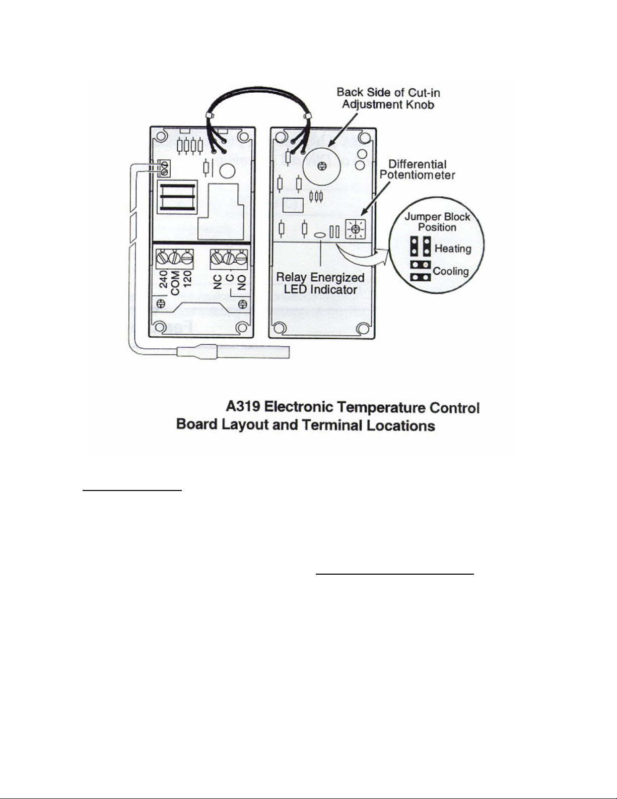
TEMPERATURE CONTROL –
The electronic temperature control is located in the electrical box. The
temperature control does not have an
‘OFF’ position. Adjustments may be
made by turning the knob on the face of
the dial. Turning it clockwise will give
warmer temperatures while counterclockwise will give colder temperatures.
There is also an adjustable temperature
differential (the difference between the
cut-in temperature and the cut-out temperatures) located on the back of the temperature control cover. When adjusting
the differential, the temperature setting
may also have to be adjusted.
A picture of this Electronic Temperature Control board layout and terminal location is on the next page.
The control has a range of –20ºF to
+100ºF with a differential of 1º to 30º. It
is factory set for approximately –18F with
an 10º differential. The temperature
should be checked with a thermometer
other than the case thermometer after it is
running to insure that the case is running
at the proper temperature for the product.
Page 8
THERMOMETER –
The thermometer is located by
looking through the right hand door onto
the right hand end of the fan plenum.
The thermometer will also warm up
rather rapidly when the case door is held
open for a time such as when the case is
being restocked or a shopper is making a
decision on a product.
After the door is closed it will take some
time for the thermometer to pull back
down to the case temperature. The thermometer and temperature control sense
discharge air temperature which is 5-10º
colder than the case temperature.
ELECTRICAL ENCLOSURE
–
The electrical enclosure contains
the defrost time clock and temperature
control. For servicing convenience, access
is gained by removing the access panel
and electrical box cover.
Page 9

THE CABINET SUPPLY BREAKERS
SHOULD BE DISCONNECTED BEFORE REMOVING THE ENCLOSURE
COVER.
DEFROST TIME CLOCK –
The timer is factory pre-set for two
defrost cycles per day at 6:00 a.m. and
10:00 p.m. with a 40 minute failsafe. The
timer must be adjusted to the proper time
of day when the cabinet is started. The
timer is adjusted by turning the knurled
adjustment knob in the center of the dial
face counter-clockwise until the time indicator corresponds with the correct time of
day. The defrost pins should be checked
for tightness. The timer will require readjusting after a power failure or the
cabinet supply is turned off for extended
periods of time. If an additional defrost is
required due to ambient or cabinet usage
conditions, do not put a defrost during the
middle of the day. Put any additional defrost during the night or a time when the
cabinet has the lowest usage.
Defrost is time initiated and temperature terminated. If cases are multiplexed, the defrost thermostats can be
wired in series so that the cases can be
temperature terminated.
If the thermostat should fail, the
timer is equipped with a failsafe set at 40
minutes that will allow defrost to terminate on time.
DEFROST HEATER THERMOSTAT –
The defrost heater thermostat is
clamped to the evaporator outlet tube. It
is a bi-metal thermostat that is tied in series with the evaporator fans for a delay
and with defrost time clock solenoid to end
defrost when the temperature has been
satisfied. The evaporator fans will not
come on until the thermostat senses 32ºF
and defrost will terminated when the stat
senses 58ºF.
DEFROST HEATER REPLACEMENT
The defrost heaters are firmly embedded in the evaporator and held in place
with spring clips. To remove the heater,
first remove all the spring clips and pull
the defective heater out of the slots in the
evaporator, starting at the wire supply
lead.
The replacement heater should be
firmly seated in the slots by using a small
block of wood and a mallet. After the new
heater is in place, replace all of the spring
retaining clips to assure heater retention.
One lead of the defective heater may be
used to pull the new leads through the
cabinet to the respective terminals as
marked on each lead.
NOTE: Care must be taken to make sure
the drain stub is correctly inserted in the
cabinet drain tube for proper drainage.
Page 10

LIGHTING –
Interior lighting is provided by
electronically powered T-8 lamps located
inside each doorway. The tubes are enclosed in a patented lens system to maintain proper heat around the bulb for
maximum, light intensity and to protect
the product in case of breakage. See the
Anthony “ELS” instructions for lens removal, attached at the back of this booklet.
Each HGL model has a convenient
ON/OFF switch so lights may be turned
off to conserve energy during hours when
the store is closed. The switch is located
inside the cabinet above the left hand
door. This switch only controls the lights.
208-230 volt power must be shut off at the
main power supply source located within
the store prior to starting any service or
maintenance work.
Light ballasts are located in the
mullions of the door frames. See the Anthony ballast removal instructions at the
back of this installation booklet.
DOOR SWITCHES –
The switches at the top of the doorways operate the evaporator fan motors.
These switches stop the fan motors when
the doors are open.
Page 11
DOOR FRAME HEATERS –
This cabinet is equipped with both
frame and door heaters. These are thermostatically controlled and will not come
on until the cabinet is at operating temperature. See door mfg. instructions for
heater replacement at the back of this
booklet
ALARM THERMOSTAT (Heater Delay)
The alarm (heater delay) thermostat is located on the top of the inner liner
in the upper right hand corner behind the
evaporator. The thermostat will not turn
the heaters on until it senses 0º and in
turn will turn the heaters off when its
senses +18º F. This is so that unwanted
heat will not be added to the case during
defrost or if the case refrigeration system
fails.
EXPANSION VALVE ADJUSTMENT –
Expansion valve must be adjusted
to fully feed the evaporator. Before attempting to adjust the valve make sure
the evaporator is either clean or only
lightly covered with frost, and that the
cabinet is within 10º of its expected operation temperature. Adjust the expansion
valve as follows:
Attach two sensing probes to the
evaporator, one under the clamp holding
the expansion valve sensing bulb and the

other securely taped to one of the return
bends two thirds of the way through the
evaporator circuit. Some “hunting” of
the expansion valve is normal. The valve
should be adjusted so that during the
hunting the greatest difference between
the two probes is 3º to 5ºF.
Remove valve stem cover and turn
valve stem counter-clockwise to decrease
temperature difference between the
probes. To increase temperature difference of probes, turn the valve stem clockwise. With this adjustment, during a portion of the hunting the temperature differences between the two probes may be
less than 3ºF, or at times as low as 0ºF.
Make adjustments of no more than
one half turn of the valve stem at a time
and wait for at least fifteen minutes before rechecking probe temperature and
making further adjustments. Replace
and tighten cover of the valve stem.
REFRIGERATION –
As stated previously, these cases
can be designed for single or multiplexed
installations. The following is a description of a 'packaged system' which includes the case, a factory-designed condensing unit, electrical line set, and refrigeration line set. These systems come precharged for easy field installation.
If it should become necessary to
leak test the system, please adhere to the
following notice:
NOTICE: BECAUSE OF THE CFC ATMOSPHERIC CONSIDERATIONS
BEING TAKEN TODAY, WE ASK
THAT LEAK TESTING BE DONE WITH
REFRIGERANT 22 MIXED WITH NITROGEN.
IF THE CONDENSING UNIT
NAMEPLATE DESIGNATES A REFRIGERANT OTHER THAN R-22 REMOVE ALL R-22 FROM THE IMMEDIATE AREA TO AVOID CONFUSION
AFTER LEAK TESTING AND EVACUATING THE UNIT. RECHARGE THE
UNIT WITH PROPER REFRIGERANT.
LEAK TESTING –
***** CAUTION*****
The test gas cylinder must be
equipped with a pressure gauge and regulator so that system test pressures do not
exceed maximum allowable limits. Do not
ever use anything other than a R-22 / Nitrogen mixture for leak testing.
Attach a refrigerant test gas cylinder to your service manifold and connect
the manifold to the charging port on the
liquid line valve. Charge an R-22 / Nitrogen mixture into the system, raising the
pressure to the remote unit’s nameplate
for the low side and high side pressures.
Using an electronic detector, carefully
check the entire system for leaks. Take
special care to inspect all brazed and flare
connections.
EVACUATION –
After the system is proven leak
tight, thoroughly evacuate the system according to the following procedure:
Page 12

√
Discharge the refrigerant-nitrogen
mixture, allowing it to blow from the
system as rapidly as possible, into an
empty cylinder. Be sure that all service valves and solenoid valves are
open to allow all of the mixture to be
discharged.
√
Connect a deep-drain vacuum pump
to both the high and low side of the
system. Pull a vacuum on the system
to at least 1500 microns.
√
Break the vacuum by adding refrigerant into the system until the pressure
is above 0 psig. Always charge the refrigerant line into the system through
a new drier in the charging manifold
line. A 16 cubic inch drier is sufficient
for this purpose.
√
Repeat steps 2 and 3 two more times,
the third time evacuating the system
to 500 microns.
REMOTE CONDENSING UNIT -
The remote condensing unit is constructed of weather resistant G-90 galvanized steel for durability. It includes the
compressor, condenser, head pressure bypass valve, receiver (insulated), crankcase
heater, drier, sight glass, condenser fan
motors, fan delay thermostat, dual pressure control, solenoid valve, electrical
box, and quick connects (optional).
COMPRESSOR –
The compressor is mounted on
Page 13
semi-rigid, rubber pads. There are no
mounting springs so the compressor is essence becomes solid mounted. DO NOT
LOOSEN THE MOUNTING BOLTS ON
THE COMPRESSOR.
FAN DELAY THERMOSTAT –
The fan delay thermostat is connected to the left hand fan motor (as you
face the unit from the electrical box side)
and will leave this fan off at ambients below 65ºF to insure proper condensing temperatures.
HEAD PRESSURE BY-PASS VALVE –
The head pressure by-pass valve is
a pre-set, non-adjustable type. Its function
is to divert the refrigerant to the receiver
when the head pressure falls below the setting so that proper head pressure is maintained in the system and liquid is feeding
the thermostatic expansion valve.
CRANKCASE HEATER –
The crankcase heater is located below the compressor on semi-hermetic models and wrapped around on hermetic models. The heater is on at all times.
CRANKCASE PRESSURE REGULATOR –
The remote units designed for the
HGL-1-T/B and HGL-2-T/B employ a
crankcase pressure regulator in the suction
line. The CPR is set for 10 psi on the remote unit for both 1 and 2 door. The purpose of the valve is to maintain a low suction pressure on start-up so that the

compressor will start properly. On startup, the valve will hold the suction pressure at the desired setting until the suction pressure has dropped below the setting, then the valve will open.
If it becomes necessary to check or
reset the valve, the case must be warm
such as after a defrost cycle or from an
initial warm case condition. Put a suction
compound gauge on the compressor suction valve, start the compressor. If the
pressure needs to be reduced turn the adjustment screw clockwise or, counterclockwise to raise the pressure. DO NOT
SET THE VALVE BASED ON THE
NAMEPLATE AMPERAGE RATING
AS THE PRESSURE SETTING WILL
BE TOO HIGH AND THE COMPRESSOR WILL NOT START PROPERLY.
ELECTRICAL BOX –
The electrical box comes pre-wired
except for the electrical line set coming
from the cabinet. Consult the wiring diagram for proper wiring. There is a power
switch in the box for the compressor and
a separate one for the crankcase heater.
ELECTRICAL LINE SET
When the electrical line set is employed, power is brought to the case first
and the line set is installed between the
case and the remote unit. Consult the
wiring diagram for proper wiring.
BOTTOM MOUNT VERSIONS -
The refrigeration line set is
provided with quick-connect connections
on both ends for installation at the case
and the remote unit.
The line set is tagged with the end
that is to be attached at the case. The line
set is tagged with the end that is to be attached at the case end.
Do not over tighten the quick connects as this will damage the seals.
After the quick connects are installed at the case end, the factory supplied
‘insulating boot’ must be sealed with contact cement to prevent air leakage that can
cause ice and water to build up on the case.
Nylon ties are further provided to seal the
ends but should not be used solely to seal
the ends. Do not over tighten the ties.
TOP MOUNT VERSIONS –
The refrigeration line set is provided with quick connects to mount to the
remote condensing unit. The lines are factory installed and sealed at the case end.
Care should be taken when uncoiling the
line set. Do not over tighten the quick connects as this will damage the seals.
PUMPDOWN SYSTEM ON THE
REMOTE UNIT
-
Operation
– The pumpdown system shuts
off the flow of refrigerant in the high side
liquid line when the case cycles off or during a defrost cycle and pumps the refrigerant from the evaporator into the condenser
and receiver.
Page 14

TROUBLE SHOOTING, LIGHTING TROUBLE SHOOTING
WARRANTY and ELECTRONIC LIGHTING
SYSTEM INSTRUCTIONS
TROUBLE SHOOTING CHARTS
TROUBLE PROBABLE CAUSE SOLUTION
Compressor runs continuously, Product too warm
1. Short of refrigerant 1. Leak check. Change
drier. Evacuate and recharge
2. Inefficient compressor 2. Replace
3. Dirty condenser 3. Clean
High head pressure 1. Cabinet location too
1. Relocate cabinet
warm
2. Restricted condenser air
flow
3. Defective condenser fan
2. Clean condenser to remove air flow restriction
3. Replace
motor
4. Air or non-condensable
gases in system
4. Leak check., change
drier, evacuate, and recharge
5. Defective fan delay ther-
5. Replace
mostat
Warm storage temperatures 1. Temperature control not
1. Reset control
set properly
2. Short of refrigerant 2. Leak check, change
drier, evacuate, and recharge.
Page 15

TROUBLE SHOOTING CON’T
3. Cabinet location too
3. Relocate
warm
4. Too much refrigerant 4. Change drier, evacuate,
and recharge
5. Low voltage. Compres-
5. Check power
sor cycling on overload
6. Condenser dirty 6. Clean
7. Dual pressure control
7. Reset control
not properly
Compressor runs continu-
1. Defective control 1. Replace
ously. Product too cold
2. Control feeder tube not
2. Assure proper contract
in positive contract
3. Short on refrigerant 3. Leak check, change
drier, evacuate, and recharge
Compressor will not start,
no noise
2. Defective or broken wir-
1. Blown fuse or breaker 1. Replace fuse or reset
breaker
2. Repair or replace
ing
3. Defective overload 3. Replace
4. Defective temperature
4. Replace
control
5. Power disconnected 5. Check service cord or
wiring connections
6. Defective dual pressure
6. Replace
control
7. Defective solenoid valve 7. Replace
Page 16

TROUBLE SHOOTING CON’T
Compressor will not start,
1. Low voltage 1. Contact electrician
cuts out on overload
2. Defective compressor 2. Replace
3. Defective relay 3. Replace
4. Restriction or moisture 4. Leak check, replace
drier, evacuate and recharge
5. Inadequate air over con-
5. Clean condenser
denser
6. Defective condenser fan
6. Replace
motor
7. CRO not set properly 7. Reset to 10 psi.
Icing condition in drain pan 1. Low voltage 1. Check voltage at com-
pressor
2. Cabinet not level 2. Check front to rear level-
ing, adjust legs accordingly
3. Defective drain tube
3. Replace
heater
4. Defective drain pan
4. Replace
heater
LIGHTING SYSTEM
Lights won’t start 1. Check light switch
2. Check continuity to ballast
3. Check to see if bulbs are inserted properly into sock-
ets
4. Check voltage
Page 17

LIGHTING SYSTEM
Lights flicker 1. Allow lamps to warm up
2. Check lamp sleeve for cracks
3. Check sockets for moisture and proper contact
4. Bulb replacement may be necessary
5. Check voltage
6. New bulbs tend to flicker until used
Ballast hums 1. Check voltage
2. Replace ballast
ELECTRICAL COMPONENTS
MODEL HGL-1-T/B HGL-2-T/B HGL-3-T/B
Evaporator Fan Morrill SPB5EM2 Same Same
Motor
Light Ballast Huss. #06-S183-1 06-S-183-1 (1) 06-S-183-2 (2)
06-S-183-2 (1)
Fluorescent lamp FO4OW-T8-60” Same Same
Page 18

WARRANTY –
Please read carefully to assure prompt and accurate service
Ordering Replacement Parts –
Contact your nearest Hussmann Distributor.
Always specify model and serial number of cabinet.
If correct part number is not known, give a clear description of part itself and its function
in the cabinet or remote unit.
Warranty Parts Procedure –
Same as items above
Give original installation date of cabinet and, if possible, forward a copy of the original
invoice or delivery receipt.
All shipments of in-warranty replacement parts will be invoiced from the factory until
such time as the defective part is returned and proved to be defective by our Quality Control Department.
Contact your Hussmann Distributor for instructions on returning in-warranty parts.
Warranty parts must be returned to the factory within 30 days of date of failure to assure
proper disposition.
Lack of any of the above information may result in the shipment of the wrong part, or a
delay in shipment.
Page 19

Compressor Replacement Procedure –
Replacement compressors will not be shipped from the Hussmann factory. They may be
obtained from your nearest Copeland Wholesaler.
Your wholesaler will replace, free of charge, any compressor found to be defective
within twelve months of installation, not to exceed twenty months from the date of
manufacture, as determined by the compressor serial number on the compressor serial
plate.
For any defective compressor beyond the twelve or twenty month time period, a salvage
value credit will be given too partially offset the invoice for the replacement.
To obtain reimbursement forward to: Hussmann Corporation
140 East State Street
Gloversville, NY
12078
the following information:
1. The cabinet model and serial number
2. A copy of the wholesaler’s invoice, along with a copy of the salvage value credit.
WIRING DIAGRAMS ARE ATTACHED AT THE BACK OF THIS BOOKLET
Page 20


FRAME HEATERS
DOOR & FRAME HEATERS
BLU
GREY
BRN
ORN
DOOR HEATERS
FAN SWITCH
BRN
BLU
LIGHT SWITCH
LAMP
ORN
ORN
BRN
BRN
BLK
3
WHT
4
8
BALLAST
9
10
1
RED
2
RED
5
BLU
6
BLU
7
LAMP
SENSING
BULB
DEFROST CLOCK
T
1
3
ALARM STAT
4
2
X
N
DEFROST HTRS
DRAIN
TUBE
HTRS
COMM
240 AC 120 NC C NO
BLK
BLK
SENSOR
RED
DRAIN PAN HTRS
BLK
JUMPER
***
***
***
***
***
RED
BLK
BLK
RED
ORN
WHT
RED
BRN
BLK
BLK
BLK
BLK
GRD
BLK
BLK
BLK
***
1 2
3 4
5 6
7 8
9 10
11 12
13 14
15 16
17 18
19 20
21 22
23 24
25 26
27 28
29 30
31 32
33 34
35 36
37 38
***
***
RED
***
***
ORN
BLK
DEFROST
THERMOSTAT
P
Z
BLK
EVAP FANS
S8
S7
REV EO # REV DATE REV BY
APPROVED BY
ELIMINATED OPTIONAL CONDENSATE PAN HEATER
-
-
-
-
B
06/24/03 JLS
-
PUR
RED
BLK
NOTE:
WIRES NOTED WITH ARE IN
WIRE HARNESS UP BACK OF CASE
S6
RED
BLK
S5
TC2
3
1
TOLERANCES UNLESS OTHERWISE SPECIFIED: FRACTIONAL 1/32"
DECIMAL 0.031" ANGULAR 1° HOLE LOCATION & SPACING 1/64"
GRD
TO
CONDENSING
}
UNIT
EO NUMBER
DRAWN BY:
DATE DRAWN :
APPROVED BY:
208-230 V
60 Hz
5224
1 PH
-
JWL
2/23/96
ANTHONY FRAME
***
SCALE
INCHES
SHEET #
1 OF 1
M100-2024R B
HGL-1-B
HGL-1-T
GLOVERSVILLE, NY 12078
WIRING DIAGRAM

SENSING
BULB
DEFROST CLOCK
T
3
1
FRAME HEATERS
4
X
2
DOOR & FRAME HEATERS
ALARM STAT
DEFROST HTRS
N
BLK
BLU
RED
BLK
BLK
DRAIN
TUBE
HTRS
COMM
240 AC 120 NC C NO
DRAIN PAN HTRS
SENSOR
BLK
JUMPER
***
RED
***
***
***
***
BLK
RED
ORN
WHT
RED
BRN
BLK
BLK
BLK
BRN
BLK
GRD
BLK
BLK
BLK
FAN SWITCHES
ORN
DOOR HEATERS
***
1 2
3 4
5 6
7 8
9 10
11 12
13 14
15 16
17 18
19 20
21 22
23 24
25 26
27 28
29 30
31 32
33 34
35 36
37 38
BRN
***
***
BLU
***
ORN
RED
BLK
***
LIGHT SWITCH
ORN
8
ORN
9
BRN
10
BRN
1
LAMP
DEFROST
THERMOSTAT
P
Z
BLK
EVAP FANS
S8
S7
REV EO # REV DATE REV BY
APPROVED BY
ELIMINATED OPTIONAL CONDENSATE PAN HEATER
-
-
-
-
B
06/24/03 JLS
-
PUR
RED
BLK
BALLAST
S6
S5
BLK
3
WHT
4
RED
2
RED
5
BLU
6
BLU
7
LAMP
OPTIONAL DISCHARGE AIR SENSOR
NOTE:
WIRES NOTED WITH ARE IN
WIRE HARNESS UP BACK OF CASE
RED
BLK
TC2
3
1
TOLERANCES UNLESS OTHERWISE SPECIFIED: FRACTIONAL 1/32"
DECIMAL 0.031" ANGULAR 1° HOLE LOCATION & SPACING 1/64"
GRD
TO
CONDENSING
}
UNIT
EO NUMBER
DRAWN BY:
DATE DRAWN :
APPROVED BY:
208-230 V
60 Hz
1 PH
5224
JWL
1/23/95
-
8
BALLAST
9
10
1
ANTHONY FRAME
***
SCALE
INCHES
SHEET #
1 OF 1
BLK
3
WHT
4
RED
2
RED
5
BLU
6
BLU
7
LAMP
HGL-2-B
HGL-2-T
GLOVERSVILLE, NY 12078
WIRING DIAGRAM
M100-2025R B

SENSING
BULB
DEFROST CLOCK
T
1
DOOR & FRAME HEATERS
FRAME HEATERS
3
4
X
2
N
ALARM STAT
BLK
BLU
RED
BLK
DEFROST HTRS
SENSOR
BLK
JUMPER
COMM
240 AC 120 NC C NO
RED
***
***
***
***
***
BRN
GRD
BLK
BLK
DRAIN PAN HTRS
DRAIN
TUBE
HTRS
PUR
RED
ORN
WHT
RED
BRN
BLK
BLK
BLK
BLK
BLK
BLK
BLK
BLK
DOOR
HEATERS
BLK
FAN SWITCHES
ORN
1 2
3 4
5 6
7 8
9 10
11 12
13 14
15 16
17 18
19 20
21 22
23 24
25 26
27 28
29 30
31 32
33 34
35 36
37 38
***
BRN
***
***
BLU
***
ORN
RED
***
BLK
LIGHT SWITCH
ORN
8
ORN
BRN
BRN
LAMP
P
BALLAST
9
10
1
DEFROST
THERMOSTAT
Z
BLK
EVAP FANS
S5
S7
TC2
PUR
RED
BLK
REV EO # REV DATE REV BY
APPROVED BY
ELIMINATED OPTIONAL CONDENSATE PAN HEATER
-
-
-
-
C
09/22/03 JLS
-
BLK
3
WHT
4
RED
2
RED
5
BLU
6
BLU
7
LAMP
NOTE:
WIRES NOTED WITH ARE IN
WIRE HARNESS UP BACK OF CASE
RED
BLK
3
1
TOLERANCES UNLESS OTHERWISE SPECIFIED: FRACTIONAL 1/32"
DECIMAL 0.031" ANGULAR 1° HOLE LOCATION & SPACING 1/64"
GRD
TO
CONDENSING
}
UNIT
EO NUMBER
DRAWN BY:
DATE DRAWN :
APPROVED BY:
208-230 V
60 Hz
1 PH
5263
JWL
2/23/96
-
ORN
8
9
10
1
BALLAST
ORN
BRN
BRN
LAMP
ANTHONY FRAME
SCALE
INCHES
SHEET #
1 OF 1
M100-2026R C
BLK
3
WHT
4
RED
2
RED
5
BLU
6
BLU
7
LAMP
***
HGL-3-B
HGL-3-T
GLOVERSVILLE, NY 12078
WIRING DIAGRAM
 Loading...