

Page 1
HGL- 1, 2 & 3 BS, TS
®
Bottom / Top Mount
Low Temperature
Remote and Self Contained
Glass Door Merchandisers
HGL-2BS
Operation Manual
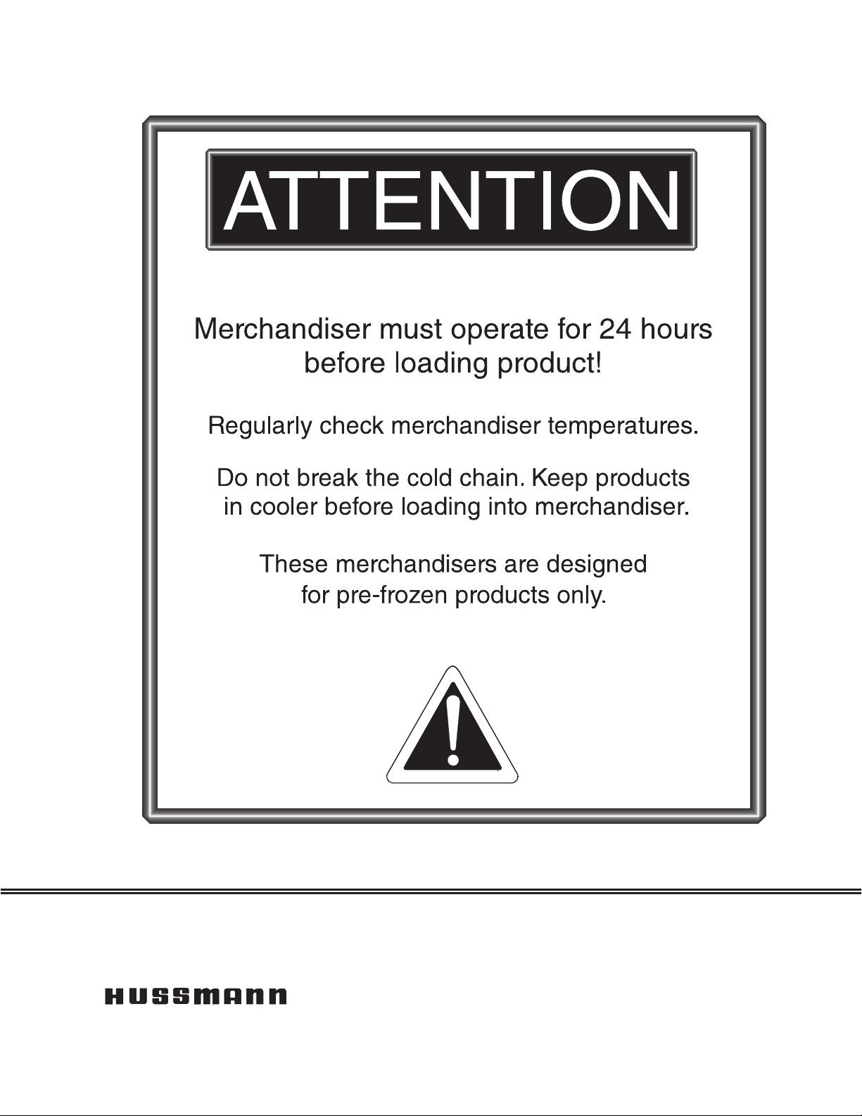
IMPORTANT
Keep in store for future reference!
HGL-3TS
Installation &
P/N 0515296_E
April 2015
Spanish 0531287
French 0531288
Page 2

Page 3
P/N 0515296_E iii
®
IMPORTANT
KEEP IN STORE FOR FUTURE REFERENCE
Quality that sets industry standards!
12999 St. Charles Rock Road • Bridgeton, MO 63044-2483
®
U.S. & Canada 1-800-922-1919 • Mexico 1-800-522-1900
www.hussmann.com
© 2015 Hussmann Corporation
Page 4

Page 5

P/N 0515296_E TABLE OF CONTENTS v
ANSI DEFINITIONS ................. vi
INSTALLATION
Certification
Hussmann Product Control
Shipping Damage
Location
Self Contained Location
Model Description
Unloading
Exterior Loading
Shipping Skid
Merchandiser Leveling
Leg Installation
Serial Plate Location
Refrigeration Unit Access
Sealing Merchandiser to Floor
........................ 1-1
........... 1-1
................... 1-1
........................... 1-1
.............. 1-2
.................. 1-4
......................... 1-4
.................... 1-4
...................... 1-4
............... 1-5
(Top Mounts Only) ....... 1-5
................. 1-5
............. 1-6
......... 1-6
Air Distribution & Rear Flue Spacer
Shelves
Checklists
............................ 1-6
.......................... 1-7
.... 1-6
Display ............................ 3-2
Start-Up
Sequence of Operation Diagram
Alarms and Codes
Defrost Termination Switch
Manual Defrost
Temperature Adjustment
Sensor to Control Adjustment
Controls and Adjustments
Start Up
Crankcase Pressure Regulator
Receiver
TEV Adjustment
Load Limits
Stocking
Thermometer
Lighting
Door Switches
Door Defrost Heater Thermostat
Alarm Thermostat
........................... 3-2
....... 3-4
................... 3-5
........... 3-5
..................... 3-5
............. 3-6
......... 3-7
............ 3-8
........................... 3-9
......... 3-9
........................... 3-9
................... 3-10
....................... 3-11
.......................... 3-11
...................... 3-12
.......................... 3-12
..................... 3-12
...... 3-12
.................. 3-12
ELECTRICAL / REFRIGERATION
Merchandiser Electrical Data
Field Wiring
........................ 2-1
.......... 2-1
Electrical Connections . . . . . . . . . . . . . . . . 2-1
Electrical Enclosure
Power Switches
Electrical Outlet
Refrigeration (Self Contained)
Refrigeration (Remote)
Line Sizing (Remote)
Koolgas (Remote)
Compressor
........................ 2-3
Condensate Pan
Air Distribution and Rear Flue Spacer
NOTES:
........................... 2-4
.................. 2-1
..................... 2-1
..................... 2-1
......... 2-2
............... 2-2
................. 2-2
................... 2-2
..................... 2-3
.. 2-3
START UP / OPERATION
Safe-NET III User Instructions
User Instructions
.................... 3-1
........ 3-1
MAINTENANCE
Care and Cleaning
Do NOT Use:
Do:
............................... 4-1
Cleaning Stainless Steel Surfaces
Cleaning Coils
Cleaning Condensate Pan
Maintaining Fluorescent Lamps
................... 4-1
...................... 4-1
....... 4-2
...................... 4-2
............. 4-3
........ 4-4
SERVICE
Replacing Fan Motors and Blades
Replacing Thermometer
............... 5-1
Defrost Heater Replacement
Troubleshooting Guide
Lighting Problem / Solution
Replacing Door Parts
Servicing Lighting
Replacement Parts List
............... 5-2
........... 5-4
................ 5-5
................... 5-5
............... 5-6
...... 5-1
.......... 5-1
HUSSMANN CORPORATION • BRIDGETON, MO 63044-2483 U.S.A.
HGL Merchandisers
Page 6

vi
APPENDIX — TECHNICAL DATA
* * * * * * * * * * * * * * * * * * * * * * * * * *
HGL-1BS — Plan View
HGL-2BS & HGL-3BS — Plan View
HGL-1TS — Plan View
HGL-2TS & HGL-3TS — Plan View
HGL Dimensions & Electrical Data
Cross Sections and Refrigeration Data
HGL Wiring Diagrams
.............. A-1
... A-2
............. A-3
.. A-4
... A-5
.. A-6
.............. A-7
REVISION HISTORY
REVISION E — Revised Parts List
REVISION D — Added Checklists Page 1-7; Added
Warning Page 1-3; Cleaning Coils 4-3; Maintaining
Fluorescent Lights 4-4. Checklist 4-5. New Replacement
Parts List, New Wiring Diagrams, New Sensor drawing
3-7, Replacing door parts Page 5-5
REVISION C — JUNE 2013
Replaced wiring diagrams; added new for each model
A-9
ANSI Z535.5 DEFINITIONS
• DANGER – Indicate[s] a hazardous
situation which, if not avoided, will
result in death or serious injury.
• WARNING – Indicate[s] a hazardous
situation which, if not avoided, could
result in death or serious injury.
• CAUTION – Indicate[s] a hazardous
situation which, if not avoided, could
result in minor or moderate injury.
• NOTICE – Not related to personal injury –
Indicates[s] situations, which if not avoided,
could result in damage to equipment.
Updated drawing on Page 3-7
REVISION B — FEBRUARY 2012
Revised to B for Wind Chill purposes
ORIGINAL ISSUE — JANUARY 2011
P/N 0515296_E U.S. & Canada 1-800-922-1919 • Mexico 1-800-890-2900 • www.hussmann.com
Page 7
P/N 0515296_E 1-1
INSTALLATION
CERTIFICATION
These merchandisers are manufactured to
meet ANSI / National Sanitation Foundation
®
(NSF
) Standard #7 requirements. Proper
installation is required to maintain certification.
Near the serial plate, each case carries a label
identifying the type of application for which
the case was certified.
ANSI/NSF-7 Type I - Display Refrigerator / Freezer
Intended for 75°F / 55% RH Ambient Application
ANSI/NSF-7 Type II - Display Refrigerator / Freezer
Intended for 80°F / 55% RH Ambient Application
ANSI/NSF-7 - Display Refrigerator
Intended for Bulk Produce
HUSSMANN PRODUCT CONTROL
SHIPPING DAMAGE
All equipment should be thoroughly examined
for shipping damage before and during
unloading. This equipment has been carefully
inspected at our factory. Any claim for loss
or damage must be made to the carrier. The
carrier will provide any necessary inspection
reports and/or claim forms.
Apparent Loss or Damage
If there is an obvious loss or damage, it must
be noted on the freight bill or express receipt
and signed by the carrier’s agent; otherwise,
carrier may refuse claim.
Concealed Loss or Damage
When loss or damage is not apparent until
after equipment is uncrated, retain all packing
materials and submit a written response to the
carrier for inspection within 15 days.
The serial number and shipping date of all
equipment is recorded in Hussmann’s files
for warranty and replacement part purposes.
All correspondence pertaining to warranty or
parts ordering must include the serial number
of each piece of equipment involved. This is to
ensure the customer is provided with the correct parts.
Recommended operating ambient
temperature is between
65°F (18°C) and 75°F (23.9°C).
Maximum relative humidity is 55%.
LOCATION
These merchandisers are designed for
displaying products in air conditioned stores
where temperature is maintained at or below
the ANSI / NSF-7 specified level and relative humidity is maintained at or below 55%.
Placing refrigerated merchandisers in direct
sunlight, near hot tables or near other heat
sources could impair their efficiency. Like
other merchandisers, these merchandisers are
sensitive to air disturbances. Air currents
passing around merchandisers will seriously
impair their operation. Do NOT allow air
conditioning, electric fans, open doors or
windows, etc. to create air currents around the
merchandiser.
HUSSMANN CORPORATION • BRIDGETON, MO 63044-2483 U.S.A.
HGL Merchandisers
Page 8

1-2 InstallatIon
SELF CONTAINED (LOCATION)
Product should always be maintained at proper temperature. This means that from the
time the product is received, through storage,
preparation and display, the temperature of the
product must be controlled to maximize the
life of the product.
Be sure to position self contained
merchandisers properly.
HGL-TS Location
The condensing unit is located at the top of
the HGL-TS. At least 12 inches of clearance
should be allowed at the rear of the cabinet and
at the top of the merchandiser. This clearance is
necessary to provide free air movement to and
from the condenser for maximum operating
efficiency.
P/N 0515296_E U.S. & Canada 1-800-922-1919 • Mexico 1-800-890-2900 • www.hussmann.com
Page 9
P/N 0515296_E 1-3
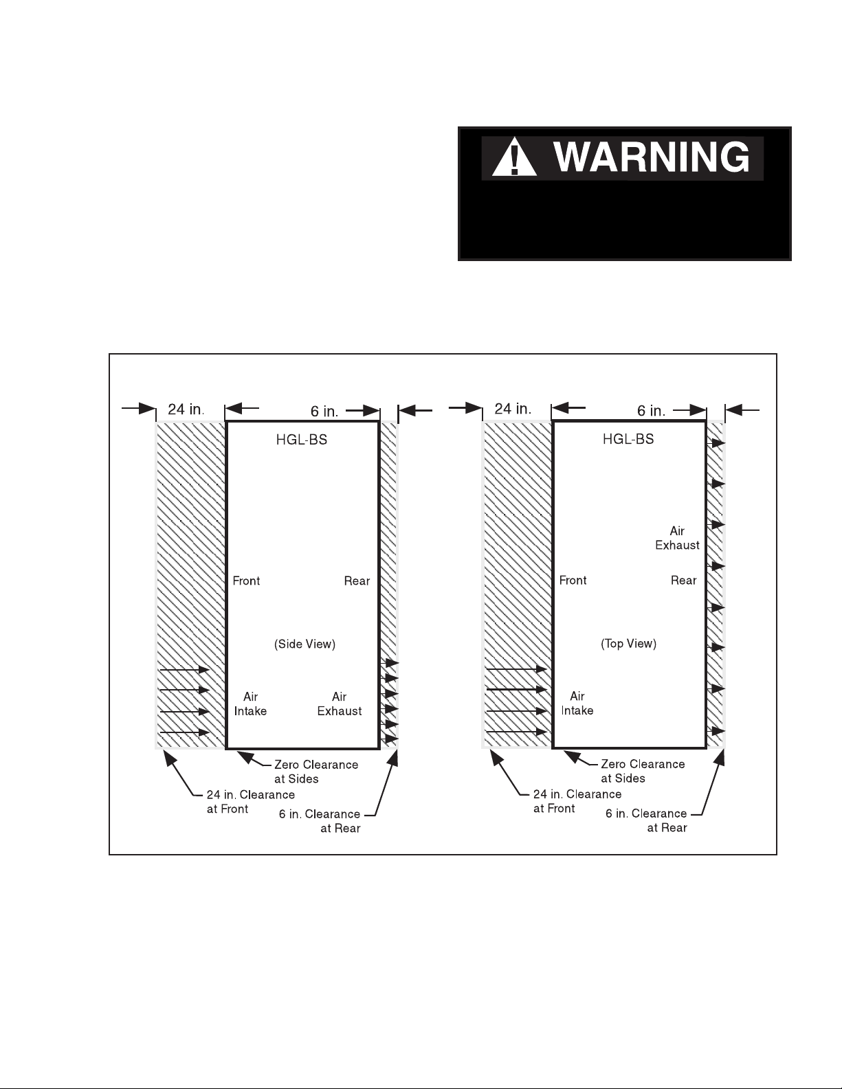
HGL-BS Location
At least 24 inches of clearance should be
maintained in front of HGL-BS merchandisers
and 6 inches of clearance at the rear to provide
the necessary free air movement to and from
Do NOT stand or walk on top of
merchandiser. Do not store items or
ammable materials atop the unit.
the condenser. The condensing unit is located
at the bottom of these merchandisers.
HUSSMANN CORPORATION • BRIDGETON, MO 63044-2483 U.S.A.
HGL Merchandisers
Page 10
1-4 InstallatIon
MODEL DESCRIPTION
Hussmann HGL-BS/TS models are self-contained,
low temperature, vertical display merchandisers.
Design features include: heated glass doors for
fog-free visibility, automatic defrost, efficient
foamed in place non-CFC insulation, cord
connection for self-contained 208-230 volt
application, and balanced refrigeration systems
for energy-saving performance.
HGL- B/T models are low temperature remote
cases. These cases do not have a condensing
unit or condensate pan.
UNLOADING
Unloading from Trailer:
Lever Bar (also known as a Mule, Johnson
Bar, J-bar, Lever Dolly, or Pry Lever)
Move the merchandiser as close as possible to
its permanent location and remove all packaging.
Check for damage before discarding packaging.
Remove all separately packed accessories such
as kits and shelves.
Improper handling may cause damage to the
merchandiser when unloading. To avoid damage:
1. Do not drag the merchandiser out of the
trailer. Use a Johnson bar (mule).
2. Use a forklift or dolly to remove the
merchandiser from the trailer.
EXTERIOR LOADING
Do NOT walk on top of merchandisers or
damage to the merchandisers and serious
personal injury could occur.
merchandisers are not structurally
designed to support external loading
such as the weight of a person. Do not place
heavy objects on the merchandiser.
SHIPPING SKID
Each merchandiser is shipped on a skid to
protect the merchandiser’s base, and to make
positioning the case easier.
Remove the top of the crate and detach walls
from each other. Lift crate from the skid.
Unscrew the case from the skid. The fixture
can now be lifted off the crate skid. Lift only at
base of skid! Remove any braces and/or skids
attached (blanket wrapped merchandiser may
have skids).
DO NOT LAY MERCHANDISER OVER
ON THE FLOOR TO REMOVE SKID.
Once the skid is removed, the merchandiser
must be lifted —NOT PUSHED— to reposition.
To remove the skid, remove screws attaching
skid to the merchandiser.
Check floor where cases are to be set to see if
it is a level area. Determine the highest part of
the floor.
Do NOT remove shipping crate until the
merchandiser is positioned
for installation.
P/N 0515296_E U.S. & Canada 1-800-922-1919 • Mexico 1-800-890-2900 • www.hussmann.com
Page 11
P/N 0515296_E 1-5
MERCHANDISER LEVELING
Be sure to position merchandisers properly.
Level the merchandiser at corners.
Merchandiser(s) must be installed level to
ensure proper operation of the refrigeration
system and to ensure proper drainage of
defrost water. The merchandiser can be leveled
by shimming under the cabinet base frame, or
by installing optional leg levelers.
The self-closing doors require the cabinet to be
properly leveled. End to end leveling will allow
the door(s) to close with uniform speed and
tightness. A slight pitch from front to rear
is desirable.
should never Be higher than the front.
the Back of merchandiser
LEG INSTALLATION (Top Mounts Only)
Install the NSF approved legs after the case is
near its final location. The legs are packaged
inside the cabinet. Replace the tape and door
blocks.
To install legs:
Raise one end of the cabinet about 8 inches.
Block the merchandiser securely, and install
two legs. The leg mounting plates are factory
installed and contain a
1
/2 x 13 in. tapped hole
to mate with the leg assembly. The procedure
is repeated on the opposite end. Three-door
merchandisers require legs in the center.
The cabinet should now be positioned at its
final location with all legs installed. The
merchandiser is leveled by turning the bottom
section of each leg. End to end leveling will
make the door(s) close with uniform speed and
tightness. A slight pitch from front to rear is
desirable.
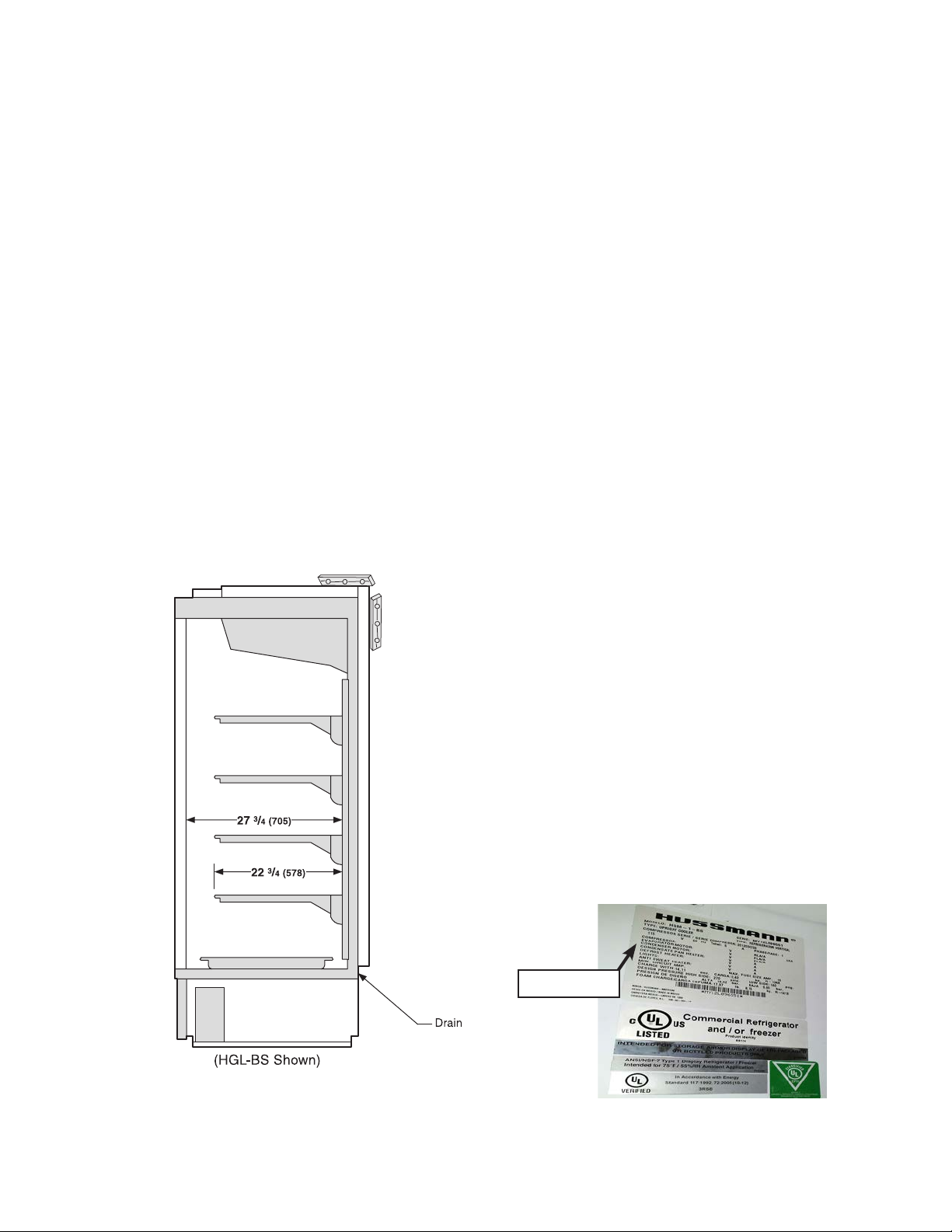
SERIAL PLATE LOCATION
The serial plate is located in the upper lefthand corner of the merchandiser’s interior.
The serial plate contains all pertinent information such as model, serial number, amperage
rating, refrigerant type and charge. Do not
remove the serial plate under any circumstance.
Serial Plate
HUSSMANN CORPORATION • BRIDGETON, MO 63044-2483 U.S.A.
HGL Merchandisers
Page 12
1-6 InstallatIon
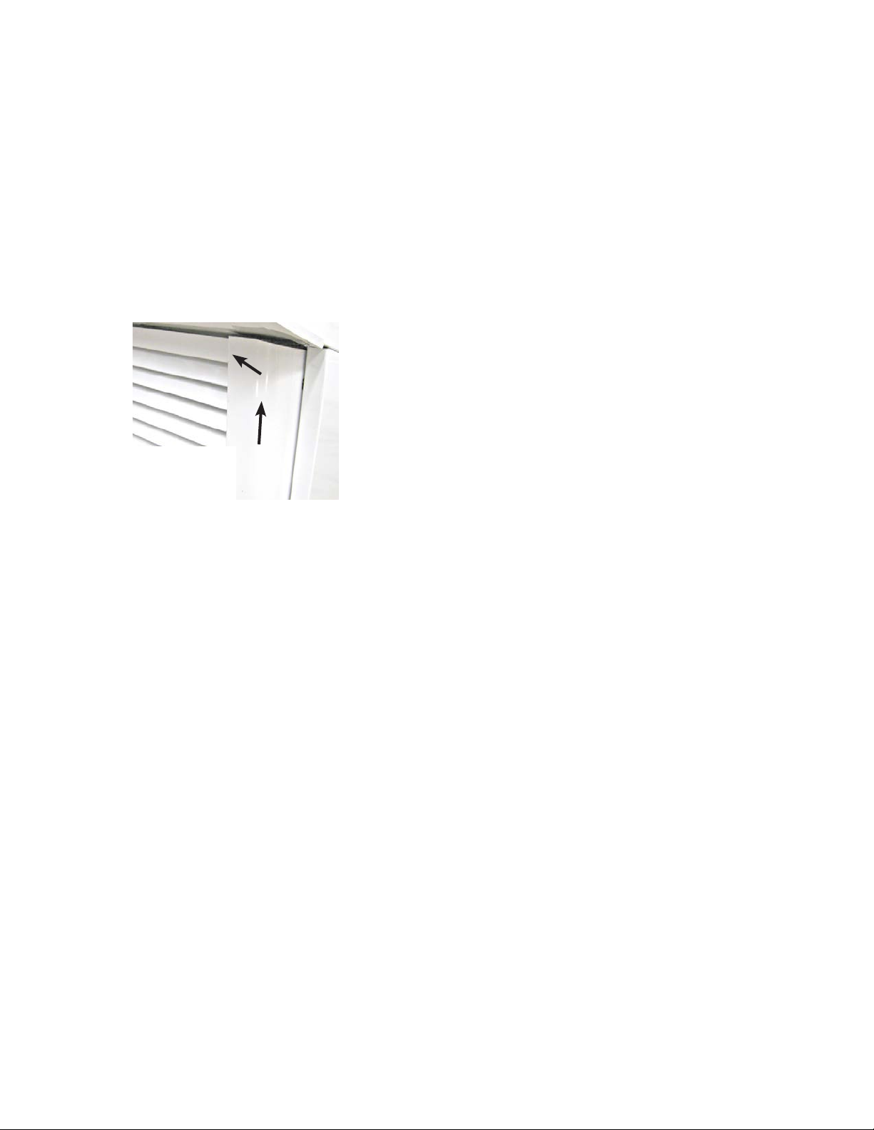
REFRIGERATION UNIT ACCESS
Top Mounts — The top decorative panel is
removed by lifting the panel up and pulling
forward.
Bottom Mounts — The lower front panel may
be removed by removing screw at bottom and
lifting the panel straight upward and over
the tabs on which it is hanging. The panel is
installed by reversing the above procedure.
Then
Lift up and
out to remove
access panel
First
Ensure lower front panel is flat against the
floor when installed to prevent air circulation
problems for self contained merchandisers.
If the condensing unit needs to be serviced, it
can be pulled out to gain access for hard to
reach components like the condenser fans.
To pull out the condensing unit, remove the
two hold down brackets, at the unit base.
Care must be given to the drain line when
re-inserting the condensing unit back into
the case. The drain line must be inside the
defrost water evaporation pan to prevent the
discharge of water on the floor.
SEALING MERCHANDISER TO FLOOR
(Bottom Mounts Only)
If required by local sanitary codes, or if the
customer desires, merchandisers may be sealed
to the floor using a vinyl cove base trim. The
size needed will depend on how much variation there is in the floor, from one end of the
merchandiser to the other. Sealing of the lower
front and rear panels on self contained models may hamper their removal for servicing or
maintenance of the condensing unit.
NOTE: Do not allow trim to cover any intake
or discharge grilles located in the lower front
panel.
AIR DISTRIBUTION & REAR FLUE
SPACER
Air is drawn through the evaporator from
front to rear and is discharged down the back
wall, returning up the face of the glass door to
the return air grille.
NOTE: Rear flue spacer must be in place as
this forms a discharge air flue at the back of
the cabinet.
SHELVES
Each cabinet is provided with four cantilever
shelves per door that are adjustable by 1 inch
increments. The shelves can also be tilted.
Each cabinet had one bottom shelf per door.
These shelves have one-inch legs to allow
proper air flow in the cabinet. Behind the
shelves are wire flues spacers, which allow for
proper air flow. All shelves and flue spacers
are white and epoxy coated for durability and
ease of cleaning.
Shelves should be adjusted to desired operating
height. Do not load product so that it touches
the evaporator coil cover. Do not extend product past the front edge of the shelf. Extending
past the edge will seriously affect internal air
flow through the cabinet. Shelves are UL rated
for a maximum load of 120 lbs.
loaD the shelves.
Do not over-
P/N 0515296_E U.S. & Canada 1-800-922-1919 • Mexico 1-800-890-2900 • www.hussmann.com
Page 13

P/N 0515296_E 1-7
Form HSCW01 Rev. 30MAY12 P/N 0525209_B
Hussmann Self-Contained Refrigerati on E quipm ent Sta rt Up Check List
***Please note that failure to follow this start-up document may void your factory warranty***
Step Startup Activity Check
1
Locate, read and maintain install/operation manual in a safe place for
future reference.
2 Examine unit. Confirm there is NO damage or concealed damage.
3 Level the unit, side to side and front to rear.
4 Remove all shipping brackets/compressor straps/bolts etc.
5
6
Unit must be run on a dedicated electrical circuit without the use of
an extension cord.
Ensure that the proper electrical requirements for the equipment are
supplied.
7 Verify field electrical connections are tight.
8
Verify all electrical wiring is secured and clear of any sharp edges or
hot lines.
9 Verify the condensate drain line is properly trapped and pitched.
10 Verify all required clearances on the sides and back of unit.
11
Advise owner/operator that merchandiser must operate at temperature for 24 hrs prior to loading
LEGAL DISCLAIMER:
Hussmann shall not be liable for any repair or replacements made without the written consent of Hussmann, or w hen the productis installed or operated in a manner
contrary to the printed instructions covering installation and service which accompanied such product.
HUSSMANN CORPORATION • BRIDGETON, MO 63044-2483 U.S.A.
Verify there are no air disturbances external to the unit. Heat and air
registers, fans, and doors etc.
with product.
HGL Glass Door Merchandisers
Page 14

1-8 InstallatIon
NOTES:
P/N 0515296_E U.S. & Canada 1-800-922-1919 • Mexico 1-800-890-2900 • www.hussmann.com
Page 15
P/N 0515296_E 2-1
ELECTRICAL / REFRIGERATION
MERCHANDISER ELECTRICAL DATA
Refer to Appendix A of this manual or the
merchandiser’s serial plate for electrical
information.
FIELD WIRING
Field wiring must be sized for component
amperes stamped on the serial plate. Actual
ampere draw may be less than specified.
ALWAYS CHECK THE SERIAL PLATE FOR
COMPONENT AMPERES
ELECTRICAL CONNECTIONS
All wiring must be in compliance with NEC
and local codes. All electrical connections (for
remote models) are to be made in the electrical
Handy Box located behind the removable base
panel at the left end of the merchandiser when
facing the discharge air louver.
Before any service is performed on this piece
of equipment, make sure the power supply to
the merchandiser is disconnected.
ELECTRICAL OUTLET:
Before the merchandiser is connected to any
wall circuit, use a voltmeter to check that the
outlet is at 100% of the rated voltage. The wall
circuit must be dedicated for the merchandiser. Failure to do so voids the warranty. Do
not use an extension cord. Never plug in more
than one merchandiser per electrical circuit.
• Always use a dedicated circuit with the
amperage stated on the unit.
• Plug into an outlet designed for the plug.
• Do not overload the circuit
• Do not use long or thin extension cords.
Never use adapters.
• If in doubt, call an electrician.
ELECTRICAL ENCLOSURE
Remove the access panel and electrical box
cover to access the electrical enclosure. The
cabinet supply breakers should be disconnected before removing the enclosure cover.
POWER SWITCHES
The power switch is located at the electrical
box, which is behind the top decorative panel
(TS models) or bottom louvered panel (BS
models). The switch will shut off all power to
the merchandiser.
HUSSMANN CORPORATION • BRIDGETON, MO 63044-2483 U.S.A.
Risk of Electric Shock. If cord or plug
becomes damaged, replace only with
a cord and plug of the same type.
— LOCK OUT / TAG OUT —
To avoid serious injury or death from electrical shock, always disconnect the electrical
power at the main disconnect when servicing
or replacing any electrical component. This
includes, but is not limited to, such items as
doors, lights, fans, heaters, and thermostats.
HGL Merchandisers
Page 16
2-2 ElEctrical / rEfrigEration
Self-contained
models have
factory-installed
power cords
attached at the
electrical box.
Merchandiser must be grounded.
Do not remove the power supply cord ground.
REFRIGERATION
(Self Contained Models)
LINE SIZING
(Remote Models)
Refrigerant line connections are made at the
left end of merchandiser (facing front) beneath
the refrigerated display area. The refrigerant
line connection size is
5
is
/8 in. Refrigerant lines should be sized as
3
/8 in. The suction line
shown on the refrigeration legend that is
furnished for the store or according to
ASHRAE guidelines.
Refrigeration lines are under pressure.
Refrigerant must be recovered before
attempting any connection or repair.
Each self contained model is equipped with
its own condensing unit. The correct type of
refrigerant will be stamped on each merchandiser’s
serial plate. The merchandiser refrigeration piping
is leak tested. The unit is charged with refrigerant,
and shipped from the factory with all service
valves open.
REFRIGERATION
(Remote Models)
Refrigeration temperature is controlled by an
electronic factory-installed thermostat. The
electronic thermostat controls a liquid line
solenoid valve (not provided with the merchandiser).
The thermostat energizes the valve as the temperature rises. A pump down system is recommended for outdoor condensing units.
For refrigerators with other than Koolgas
defrost, the suction and liquid line should be
clamped and/or taped together and insulated
for a minimum of 30 feet from the refrigerator.
KOOLGAS
(Remote Models)
If Koolgas defrost is used, the liquid line will
need to be increased two sizes larger inside the
merchandiser area. This is necessary to ensure
even liquid drainage from all evaporators
during defrost.
Refrigerators with Koolgas defrost
not have their liquid lines and suction lines in
should
contact with each other but are to be separately insulated for a minimum of 30 ft from the
refrigerator. Additional information for the
balance of the refrigerant lines is recommended
and required wherever condensation and dripping
would be objectionable.
P/N 0515296_E U.S. & Canada 1-800-922-1919 • Mexico 1-800-890-2900 • www.hussmann.com
Page 17
P/N 0515296_E 2-3
CONDENSATE PAN
Oil Traps
P-traps (oil traps) must be installed at the base
of all suction line vertical risers.
Pressure Drop
Keep refrigerant line runs as short as possible
to avoid large pressure drops. Use a minimum
number of elbows. Where elbows are required,
use long radius elbows only.
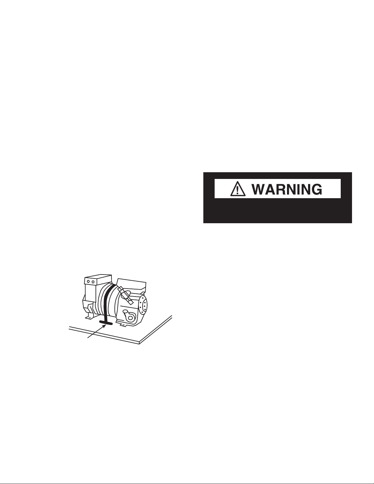
COMPRESSOR
(Self Contained)
The HGL compressor is mounted on vibration
springs. The compressor is banded down during
shipment. This band MUST be cut and removed
to allow the compressor to float freely once
placed into operation. Failure to cut compressor
shipment band may result in excessive noise or
system damage.
An electrically heated (300W, 208-230V)
condensate pan evaporates defrost water. The
heated condensate pan slides onto the slide
plate on the cabinet bottom on both the TS
and BS merchandisers.
The pan is removable for cleaning. A vinyl
drain tube is provided for connection to the
heated condensate pan. The drain must be
trapped to guard against drain line freezing
and as a good sanitation practice.
Product will be degraded and may spoil if
allowed to sit in a non-refrigerated area.
Compressor Band
HUSSMANN CORPORATION • BRIDGETON, MO 63044-2483 U.S.A.
HGL Merchandisers
Page 18

2-4 ElEctrical / rEfrigEration
NOTES:
P/N 0515296_E U.S. & Canada 1-800-922-1919 • Mexico 1-800-890-2900 • www.hussmann.com
Page 19
P/N 0515296_E 3-1
START UP / OPERATION
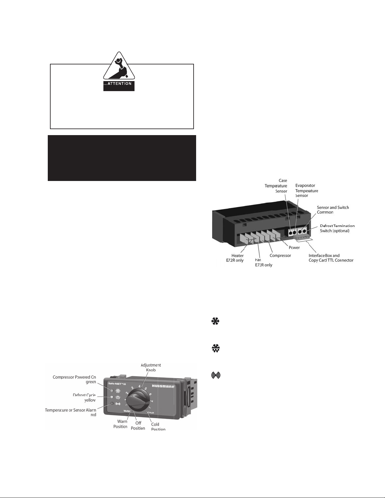
The front of the controller has an adjustment
knob and status LEDs. The back of the
IN STA LLER
controller has connections for sensors and
switched equipment.
It is the contractor’s responsibility to
install merchandiser(s) in accordance with
all local building and health codes.
Safe-NET III™
TEMPERATURE AND DEFROST
CONTROLLER
SAFE-NET III™ USER INSTRUCTIONS
Your refrigerated case uses a Hussmann
Safe-NET™ III temperature and defrost
controller to precisely maintain the temperature and prevent frost buildup on the cooling
coil. LEDs indicate when the compressor or
refrigeration is on, when the case is in a defrost
cycle, if the temperature is outside the desired
range, or if there is a sensor failure.
The Safe-NET III controller includes the
following features and connections.
• Adjustment knob:
Adjusts the temperature setpoint.
Turn adjustment knob to OFF to turn off
refrigeration system. Unplug merchandiser
from power before servicing the unit.
An adjustment knob allows the temperature
to be set within the configured range and can
power off the controller and compressor. Your
controller has been custom-configured to provide the best temperature and defrost control
for your chilled or frozen food.
HUSSMANN CORPORATION • BRIDGETON, MO 63044-2483 U.S.A.
• Controller LEDs:
Compressor Powered On LED (green):
Lights while the compressor is running or
the refrigeration valve is open.
Defrost Cycle LED (yellow):
Lights while the refrigeration coil is
defrosting.
Temperature or Sensor Alarm (red):
Lights if the temperature is too warm or
too cold. Flashes if a sensor fails.
HGL Merchandisers
Page 20
3-2 Start up / OperatiOn
START-UP / OPERATION
• Rear connections:
– Case temperature sensor:
• Typically senses the temperature
of the air in the case.
Used by the controller to determine when
to power on or power off the compressor
or refrigeration.
– Evaporator temperature sensor:
• Senses the temperature of the
refrigeration coil.
Terminates a defrost cycle when
refrigeration coil ice melts.
– Compressor or refrigeration relay:
• Switches on the compressor or
refrigeration valve for cooling.
The optional evaporator fan remains
ON when the adjustment knob is in the
Off position.
Before applying power to the merchandiser,
remove the front grille.
Locate the compressor (for self contained
models),
compressor in place. This band is only needed
cut the band holding the
for shipment, and must be cut prior to
operation.
Check thermostat knob is at the appropriate
position. See temperature adjustment on
Page 3-6.
Check the check the merchandiser’s cabinet
thoroughly for loose nuts and bolts. Check all
electrical connections. Inspect the refrigerant
lines for any visible damage or chafing.
Replace the front grille.
The following list of housekeeping practices
will assure trouble-free operation:
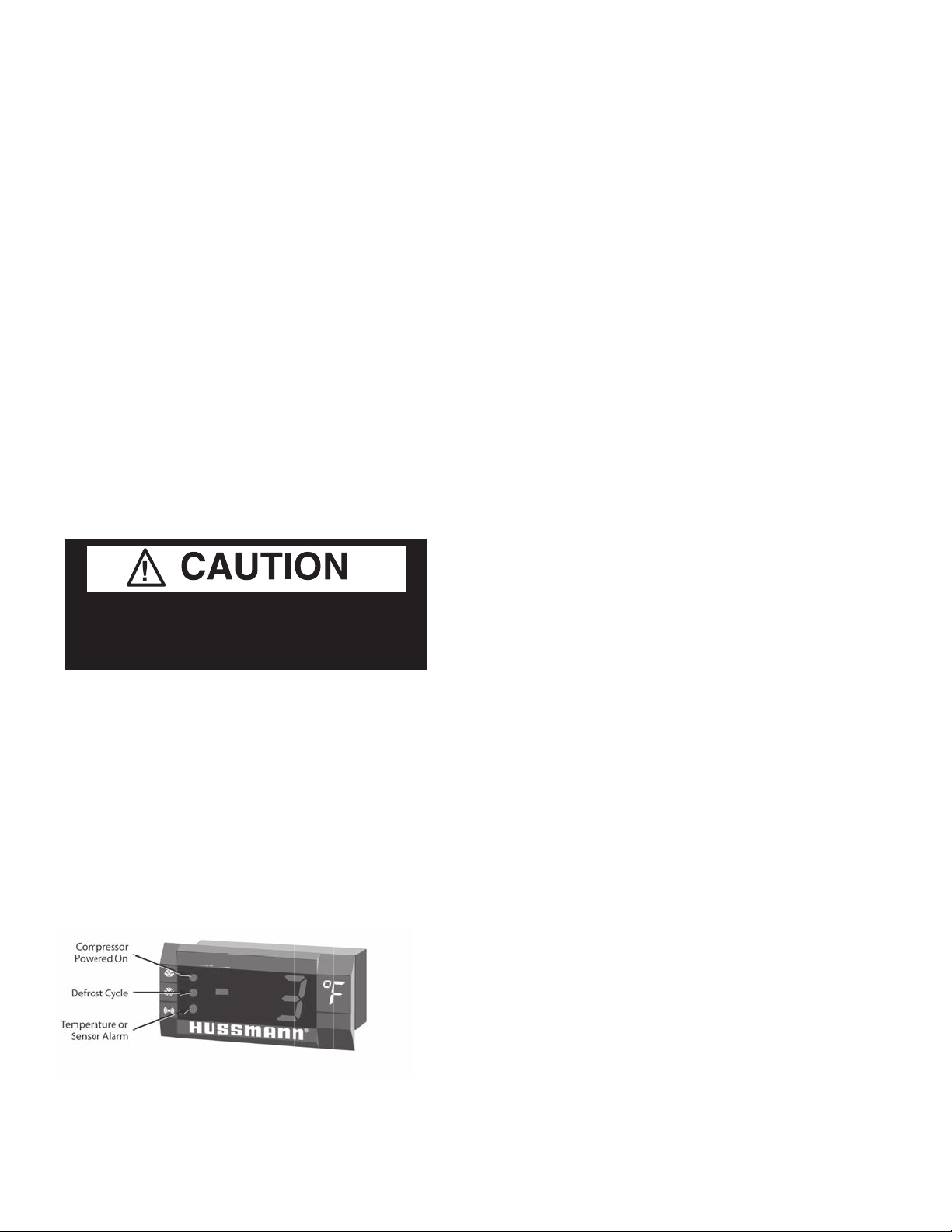
DISPLAY
The display includes three red LEDs and two
digits for temperature, defrost status, and error
codes.
The three display LEDs are red, and their
behavior matches the LEDs on the controller.
• Check operation of condenser fan motors.
Fan blades must turn freely.
• Check drain pan and heater to prevent
accidental overflow.
• Make sure doors are closing properly, and
that gaskets are sealed.
• Make sure all evaporator fan motors are
running. These can be seen through grille
inside of cabinet.
P/N 0515296_E U.S. & Canada 1-800-922-1919 • Mexico 1-800-890-2900 • www.hussmann.com
Page 21
P/N 0515296_E 3-3
START-UP / OPERATION
1. Plug in the merchandiser.
The OFF Position does not disconnect line
voltage to the case, refrigeration unit, fan,
or heater.
NOTE: The 65°C Version Controller includes
a Parameter Code Number. This number indicates what program has been loaded into the
controller. When the Controller is first powered up, or is turned off and then back on, a
2-digit parameter code number will display for
Product will be degraded and may spoil if
allowed to sit in a non-refrigerated area.
3 seconds. Then the Self Check will Start.
The Safe-NET parameter code is 63.
2. Wait for the self check to complete. During
the self check, each LED flashes for one
second, then all LEDs turn on for two
seconds. If the LEDs do not flash, make
sure the adjustment knob is not in the Off
position.
• After the self check, all LEDs turn off
until the compressor starts. There may be
a delay before the compressor starts. If the
red Temperature or Sensor Alarm LED
stays on after the self check.
• The green Compressor Powered On LED
turns on when the compressor starts.
NOTE: Do NOT load product until AFTER
merchandiser operates for 24 hours and reaches desired operating temperature.
HUSSMANN CORPORATION • BRIDGETON, MO 63044-2483 U.S.A.
HGL Merchandisers
Page 22

3-4 Start up / OperatiOn
1. Apply power to the merchandiser. Wait for
the self check to complete. During the self
check a 2 digit number will appear for 3 seconds. Then each LED flashed for one second and then all LED’s turn on for two seconds. If the LED’s do not flash, make sure
the adjustment knob is not in the “OFF”
position.
1A. The merchandiser temperature displays at
startup. The initial defrost starts two hours
later. The display will show the temperature at
the start of defrost. This reading will remain
displayed during defrost and until it times out,
even though the refrigeration mode has been
initiated. (The green LED will be lit.)
P/N 0515296_E U.S. & Canada 1-800-922-1919 • Mexico 1-800-890-2900 • www.hussmann.com
2. The compressor will start after a delay; 30
seconds after the power is applied.
3. The compressor will continue to run until it
reaches its cut-out temperature (Pulldown).
4. The refrigeration cycle will continue for the next
subsequent scheduled 12-hours or demand
defrost.
5. The above process will repeat (steps 3 and 4)
until the power is interrupted.
6. If power stops, the process will start over at
Step 1, and the time to subsequent defrost will
reset.
Page 23
P/N 0515296_E 3-5
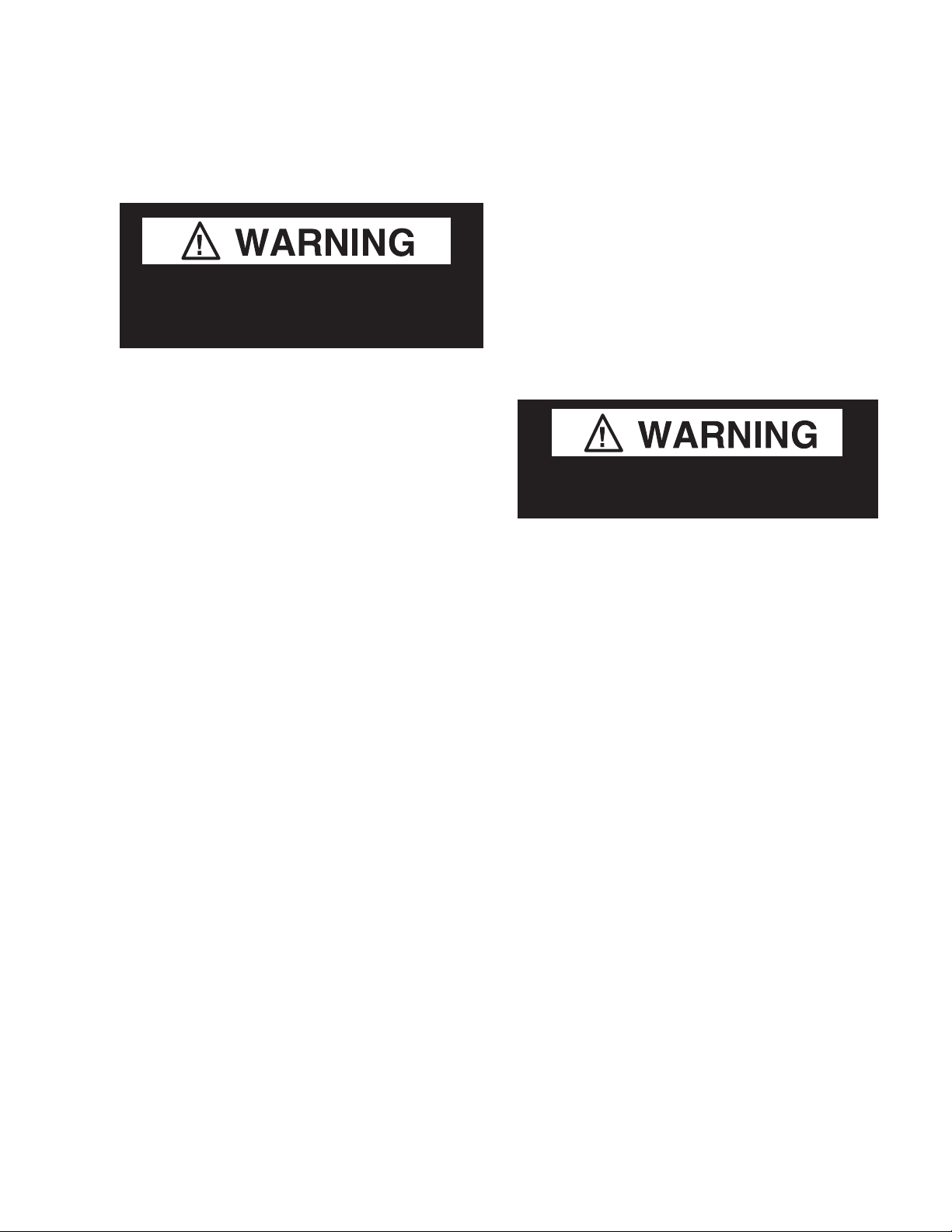
ALARMS AND CODES
Flashing temperature or sensor alarm
led, e1 or e2
If the Temperature or Sensor Alarm LED
(red) on the controller and display is flashing,
a temperature sensor has failed. The display
shows E1 if the case sensor has failed or E2 if
the evaporator sensor has failed.
If the merchandiser sensor fails, refrigeration
will run continuously. Turn off, or repeat a
duty cycle of a few minutes on and a few
minutes off.
DEFROST TERMINATION SWITCH
Merchandisers may use a defrost termination
switch, instead of an evaporator sensor to
terminate a defrost cycle. The defrost
termination switch is temperature activated
and senses the completion of defrost.
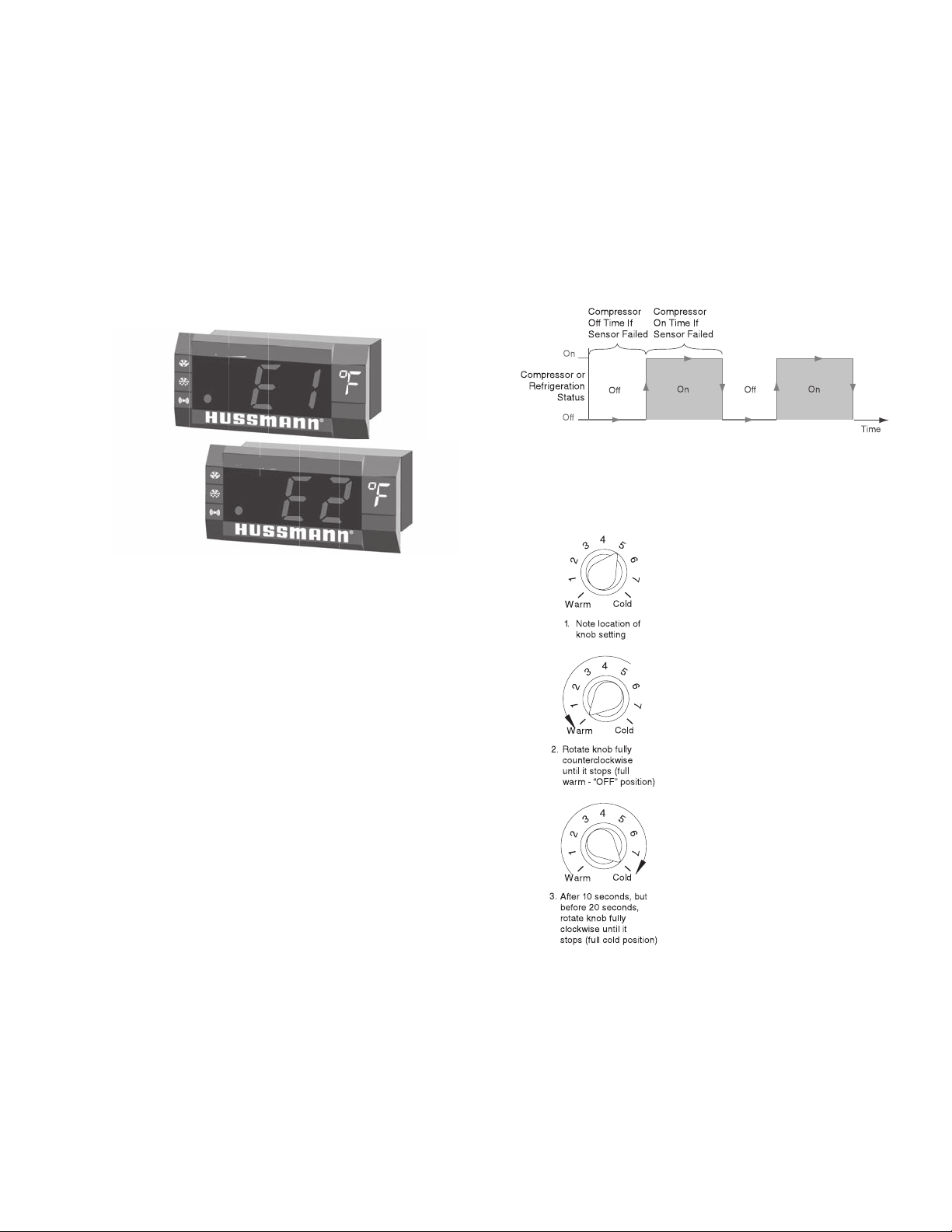
MANUAL DEFROST
Note:
This procedure initiates
a manual or forced
defrost.
HUSSMANN CORPORATION • BRIDGETON, MO 63044-2483 U.S.A.
IMPORTANT: Return the control knob to
its original setting (Step1) once the manual
defrost has been initiated.
HGL Merchandisers
Page 24

3-6 Start up / OperatiOn
TEMPERATURE ADJUSTMENT
1. Rotate the adjustment knob counter clock-
wise for a hammer setpoint or clockwise for
a colder setpoint.
2. While adjusting the temperature, the display
shows the setpoint (cut out value). A few
seconds after the temperature is set, the
controller reverts to the sensed temperature
in the merchandiser.
P/N 0515296_E U.S. & Canada 1-800-922-1919 • Mexico 1-800-890-2900 • www.hussmann.com
3. To verify merchandiser settings, perform the
operations below. Output readings should
be within one degree of the temperatures
shown above.
Page 25

P/N 0515296_E 3-7
Sensor to Control Conguration
Sensor Bracket (HGL/HGM)
Thermometer Sensor
(Black Sheath)
(x)
Safe-NET Control Sensor
(Black Sheath)
#8 Black
Sheathed Air
Sensor
#9 Yellow Sheathed
Defrost Sensor
(See page 3-10
for location
of sensor)
#10 White
(Common)
Back of Safe-NET
Control Detail
HUSSMANN CORPORATION • BRIDGETON, MO 63044-2483 U.S.A.
#11
Not Used
HGL Merchandisers
Page 26

3-8 Start up / OperatiOn
1. The Safe-NET III Controller controls refrigeration temperature. This is factory installed in
the control panel. Adjust this control knob to
maintain the discharge air temperature shown.
Measure discharge air temperatures at the
center of the discharge louver.
Defrosts are time initiated and temperature
terminated for self contained and remote,
including Koolgas models. The defrost setting
is factory set as shown above.
To ensure a thorough defrost, defrost must be
terminated by the temperature termination
setting — not by time.
P/N 0515296_E U.S. & Canada 1-800-922-1919 • Mexico 1-800-890-2900 • www.hussmann.com
Page 27

P/N 0515296_E 3-9
START UP
Follow the Safe-NET III start up procedures
as detailed in Section 3 of this manual.
Each self contained merchandiser has its own
evaporator coil and a pre-set thermostatic
expansion valve (TEV). The TEV has been
factory set at design conditions to provide the
recommended performance.
CRANKCASE PRESSURE REGULATOR
The HGL-1 and HGL-2 merchandisers employ
a crankcase pressure regulator in the suction
line. The CPR is set for 10 psi. The purpose of
the valve is to maintain a low suction pressure
on startup so that the compressor will start
properly. On start-up, the valve will hold the
suction pressure at the desired setting until the
suction pressure drops below the setting, then
the valve will open. If it becomes necessary to
check or reset the setting, the merchandiser
must be warm such as after a defrost cycle or
from an initial warm case condition.
Put a suction compound gauge on the compressor suction valve. Start the compressor.
If the pressure needs to be reduced, turn the
adjustment screw clockwise or counterclockwise to raise the pressure.
RECEIVER
NOTE: All HGL models prior to early 2014
had this receiver. New production early 2014
does not have this receiver.
The receiver should not be confused for a filter-drier
or muffler. The receiver is in the liquid line after
the condenser and just ahead of the filter drier.
The manufacturer may label the receiver as a
muffler or a drier, but it is in fact, an empty
shell.
IN STA LLER
COMPRESSOR
HGL self contained merchandiser has
a compressor that is banded down for
shipment. This band MUST be cut and
removed to allow the compressor to float
freely once placed into operation.
NOTE: Failure to cut compressor
shipment band may result in excessive
noise or system damage, which is not
covered by warranty.
do not set the valve based on the serial
plate amperage rating as the pressure
setting will be too high, and the compressor
will not start properly.
HUSSMANN CORPORATION • BRIDGETON, MO 63044-2483 U.S.A.
HGL Merchandisers
Page 28

3-10 Start up / OperatiOn
TEV Adjustment
Expansion valves may be adjusted to fully feed
the evaporator. Before attempting to adjust
valves, make sure the evaporator is clear or only
lightly covered with frost, and the merchandiser
is within 10°F of its expected operating temperature.
TXV Bulb
Sensor probe to
be located at 90°
Sensor attached
(white)
Adjust the valve as Follows:
a. Attach a probe to the suction line near the
expansion valve bulb.
b. Obtain a pressure reading from the factory
installed Schraeder valve. Convert the pressure
reading to a saturated temperature for the
refrigerant.
Temperature (b) minus Temperature (a) is the
superheat. The valve should be adjusted so that
the greatest difference between the two temperatures is 3°F to 5° F.
Make adjustments of no more than
the valve stem at a time and wait for at least
15 minutes before rechecking the probe temperature and making further adjustments.
1
/2 turn of
be located at 90°
Yellow Sensor SS Tip
Sensor probe to
TXV Bulb
Yellow Sensor
SS Tip
HGL 1-door
TXV Bulb
HGL 2-door
See replacement parts list in Section 5 of this
manual for proper TXV replacement. If you
have flare connections on TXV you must
replace with a flare style TXV. Newer models
will have sweat connections.
Sensor probe to
be located at 90°
TXV Bulb
HGL 3-door
TXV Bulb
Yellow Sensor
SS Tip
P/N 0515296_E U.S. & Canada 1-800-922-1919 • Mexico 1-800-890-2900 • www.hussmann.com
Page 29

P/N 0515296_E 3-11
LOAD LIMITS
Each merchandiser has a load limit decal. Shelf
life of perishables will be short if load limit is
violated.
Product will be degraded and may spoil if
allowed to sit in a non-refrigerated area.
At no time should merchAndisers be
stocked beyond the loAd limits indicAted.
do not block Air louvers.
STOCKING
Product should NOT be placed inside the
merchandisers until merchandisers are at
proper operating temperature.
Allow merchandiser 24 hours to operate before
loading product.
Proper rotation of product during stocking is
necessary to prevent product loss. Always
bring the oldest product to the front and set
the newest to the rear.
air discharge and return Flues must
remain open and Free oF obstruction at
all times to provide proper refrigeration and
air curtain performance. Do not allow product, packages, signs, etc. to block these grilles.
Do not use non-approved shelving, baskets,
display racks, or any accessory that could
hamper air curtain performance.
Do not load
product past
shelves
Do not allow product to be placed outside of
the designated load limits in the illustration.
HUSSMANN CORPORATION • BRIDGETON, MO 63044-2483 U.S.A.
HGL Merchandisers
Page 30

3-12 Start up / OperatiOn
THERMOMETER
The thermometer is located by looking
through the right hand door onto the right
hand end of the fan grille. The thermometer
will warm up rapidly when the merchandiser
door is held open, or when the merchandiser is
being restocked. After the door is closed it will
take some time for the thermometer to decrease
to optimal temperature. The thermometer and
temperature control senses discharge air
temperature, which is 5º to 10º F colder than
the merchandiser temperature.
LIGHTING
Electronically powered T-8 lamps, located
inside each doorway, provide interior lighting.
The tubes are enclosed in a patented lens system
to maintain proper heat around the bulb for
maximum light intensity. The tubes also protect
the product in case of breakage.
LED LIGHTS
Each HGL model has an ON/OFF switch so
lights may be turned off to conserve energy
during hours when the store is closed. The
switch is located inside the cabinet above the
left-hand door. This switch only controls the
lights. 208-230 V power must be shut off at the
main disconnect, located within the store prior
to starting any service or maintenance work.
For details showing how the LED fixtures are
mounted, see the supplemental document at the
end of this manual.
DOOR SWITCHES
The switches at the top of the doorways operate
the evaporator fan motors. These switches stop
the fan motors when the doors are open.
DOOR DEFROST HEATER THERMOSTAT
Each HGL model has an ON/OFF switch so
lights may be turned off to conserve energy
during hours when the store is closed. The
switch is located inside the cabinet above the
left-hand door. This switch only controls the
lights. 208-230 V power must be shut off at the
main disconnect, located within the store prior
to starting any service or maintenance work.
Light ballasts are accessed from the outside of
the mullion. For details showing how the T8
fixtures are mounted, see the supplemental
document at the end of this manual.
This cabinet is equipped with both frame and
door heaters. These are thermostatically controlled, and will not come on until the cabinet is
at operating temperature.
ALARM THERMOSTAT (heater display)
The alarm (heater display) thermostat is located
on the top of the inner liner in the upper right
hand corner behind the evaporator. The
thermostat will not turn the heaters on until it
senses 0º F, and in turn will turn the heaters
off when it senses +18º F. This is because the
unwanted heat will not be added to the merchandiser during defrost or if the case refrigeration system fails.
P/N 0515296_E U.S. & Canada 1-800-922-1919 • Mexico 1-800-890-2900 • www.hussmann.com
Page 31

P/N 0515296_E 4-1
MAINTENANCE
CARE AND CLEANING
Long life and satisfactory performance of
any equipment is dependent upon the care it
receives. To ensure long life, proper sanitation
and minimum maintenance costs, these
merchandisers should be thoroughly cleaned,
all debris removed and the interiors washed
down, weekly.
Exterior Surfaces
The exterior surfaces must be cleaned with a
mild detergent and warm water to protect and
maintain their attractive finish.
abrasive cleaNsers or scouriNg pads.
Never use
Interior Surfaces
The interior surfaces may be cleaned with most
domestic detergents, ammonia based cleaners
and sanitizing solutions with no harm to the
surface. Self contained models empty into a
limited capacity condensate pan, which will
overflow if excess water is used in cleaning.
Do:
•Remove the product and all loose debris to
avoid clogging the waste outlet.
•Store product in a refrigerated area such as a
cooler. Remove only as much product as can
be taken to the cooler in a timely manner.
•Disconnect electrical power before cleaning.
•Thoroughly clean all surfaces with soap and
hot water.
pressure hoses to wash the iNterior.
These will desTroy The merchandisers’
sealing causing leaks and poor perfor-
mance.
•Take care to minimize direct contact between
fan motors and cleaning or rinse water.
do Not use steam or high water
Do NOT Use:
•Abrasive cleansers and scouring pads, as these
will mar the finish.
•Coarse paper towels on coated glass.
•Ammonia-based cleaners on acrylic parts.
•Solvent, oil or acidic based cleaners on any
interior surfaces.
•Do not use high pressure water hoses.
Product will be degraded and may spoil if
allowed to sit in a non-refrigerated area.
Do NOT allow cleaning agent or
cloth to contact food product.
•Do NOT flood merchandiser with water.
Never iNtroduce water faster thaN the
waste outlet caN remove it.
self coNtaiNed models empty iNto aN
coNdeNsate paN that will overflow if too
much water is iNtroduced duriNg cleaNiNg.
•Allow merchandisers to dry before resuming
operation.
•After cleaning is completed, turn on power to
the merchandiser.
HUSSMANN CORPORATION • BRIDGETON, MO 63044-2483 U.S.A.
HGL Merchandisers
Page 32

4-2 Maintenance
CLEANING STAINLESS STEEL SURFACES
Use non-abrasive cleaning materials, and
always polish with grain of the steel. Use warm
water or add a mild detergent to the water and
apply with a cloth. Always wipe rails dry after
wetting.
Use alkaline chlorinated or non-chlorine
containing cleaners such as window cleaners
and mild detergents. Do not use cleaners
containing salts as this may cause pitting and
rusting of the stainless steel finish. Do not use
bleach.
— LOCK OUT / TAG OUT —
To avoid serious injury or death from electrical shock, always disconnect the electrical
power at the main disconnect when servicing
or replacing any electrical component. This
includes, but is not limited to, such items as
doors, lights, fans, heaters, and thermostats.
CLEANING COILS
Condenser coils should be cleaned at least
once per month. Additional cleaning may be
needed depending on the operational environment. A dirty condenser blocks normal airflow
through the coils.
Airflow blockage increases energy consumption and reduces the merchandiser’s ability to
maintain operating temperature.
To clean the coils, use a vacuum cleaner with
a wand attachment and a soft (non-metallic)
brush to remove dirt and debris. Do not bend
coil fins. Always wear gloves and protective
eye wear when cleaning near sharp coil fins
and dust particles.
Do NOT use HOT water on Cold glass Surfaces.
This can cause the glass to shatter and could
result in personal injury. Allow glass fronts, to
warm before applying hot water.
P/N 0515296_E U.S. & Canada 1-800-922-1919 • Mexico 1-800-890-2900 • www.hussmann.com
Unplug merchandiser before servicing. Always
wear gloves and protective eye wear when cleaning
coils.
Page 33

P/N 0515296_E 4-3
NEVER USE SHARP OBJECTS AROUND
COILS. Use a soft brush or vacuum brush to
clean debris from coils. Do not puncture coils!
Do not bend fins. Contact an authorized
service technician if a coil is punctured,
cracked, or otherwise damaged.
ICE in or on the coil indicates the refrigeration and defrost cycle is not operating properly. Contact an authorized service technician
to determine the cause of icing, and to make
adjustments as necessary. To maintain product
integrity, move all product to a cooler until
the unit has returned to normal operating
temperatures.
CLEANING CONDENSATE PAN
(SELF CONTAINED ONLY)
The condensate water outlet for self
contained models empties into a limited
capacity condensate pan.
Debris or dirt accumulation inside the condensate
pan or on the heater coil will reduce the pan’s
evaporation capacity and cause premature heater failure. The condensate pan waste will overflow and spill onto the floor if the heater is not
properly operating.
and poses risk of bodily injury – Always Wear gloves
and protective eye wear when servicing. Turn off
condensate pan heater, and allow pan to cool.
Use only enough water necessary to clean
surface. Water must not drip down the case!
Never use ammonia based cleansers, abrasive
Condensate Pan is Hot!
DO NOT FLOOD!
cleansers, or scouring pads.
Always wear protective eye wear and gloves
when servicing.
Remove accumulated debris from the condensate pan. Wipe down heater coil with a cloth
and warm water. Be sure to remove any dirt,
debris or liquids from the heater coil.
Water introduced during cleaning will cause
the condensate pan to overflow.
Unplug merchandiser before servicing. Always
wear gloves and protective eye wear when cleaning
condensate pan.
HUSSMANN CORPORATION • BRIDGETON, MO 63044-2483 U.S.A.
HGL Merchandisers
Page 34

4-4 Maintenance
MAINTAINING FLUORESCENT LAMPS
(IF APPLICABLE)
Many of the self-contained cases are equipped
with LEDs. For cases with fluorescent lamps,
follow these directions to ensure long-lasting
life of the lights:
Fluorescent lamps should not be allowed to
run to failure. If a re-lamp schedule is not in
place, the tubes should be inspected for signs
of degradation (blackened ends). Degraded or
failed tubes should be replaced.
Allowing severly degraded lamps to operate
may cause a ballast failure or could expose
the lamp holder to excessive heat. Replacing
degraded bulbs is more cost effective
than replacing ballast and lamp-holders.
Traditional re-lamp programs are 18-to-24
month intervals. In the absence of a re-lamp
program, a yearly inspection of the lighting
system is recommended.
1. Inspect all lamp sockets and plug-receptacle
connections for signs of arching. Replace any
component that shows signs of arching.
2. Make sure all unused receptacles have their
close-off covers securely installed.
3. Make sure proper cleaning procedures are
followed. Lights and fans MUST be turned off
when a case is cleaned and MUST be allowed to
dry before turning power back on.
4. Do not use a pressure nozzle to clean inside
of case.
P/N 0515296_E U.S. & Canada 1-800-922-1919 • Mexico 1-800-890-2900 • www.hussmann.com
Page 35

P/N 0515296_E 4-5
Record starting date
Store Address
Unit Model Number
Unit Serial Number
Contractor/Technician
Check in with store manager, record any complaints or issues
x
Lookunitoverforanydamage, vibrationsor abnormalnoise.
x
x
Confirm refrigerant lines properly are secured and not touching
or rubbing other lines, wires or frame work.
x
x
Confirm fan blade/s are tight and not r ubbing or hitting.
x
x
x
x
Check all electrical wiring make sure it is secured and not on
any sharp edges or hot lines.
x
registers,fans, and doors etc.
x
x
base cleaner. Rinse off any cleaner residue.
x
base cleaner. Rinseoff any cleaner residue.
x
Clean condenser coil/s and fan blade/s. Do not use an acid base
Cleaner. Rinseoff any cleaner residue.
x
Clean condensate drain pan and drain line.
x
x
x
x
Record condenser air inlet temperature
x
x
x
x
x
x
Record defrost heater voltage and am p d r a w.
x
Record anti-sweat heater voltage and amp draw.
x
x
Record unit discharge air temperature.
x
x
x
x
Manual for proper controller operation.
x
x
x
x
Self-Contained Refrigeration Equipment Maintenance Check List
* * * * * Warranty does not cover issues caused by improper installation or lack of basic preventative maintenance. * * * * *
Store Name and Number
Technician
PMdate
PMactivity-For visual inspection items,denote"okor
complete" inthe column to rightwhen PM has been
performed. For measured data requested, recorddata
requested in the appropriate column to the right)
they have with unit.
Verify unit is level side to side and front to rear.
Verify fan motors and motor mounts are tight.
Make sure all electrical connections, factory and field, are tight.
Verify ele ctric al connections at lamps arethey secure and dry.
Check for and replace any frayed or chaffed wiring.
Check for ai r disturbances externallto the unit. Heat and air
Check for water leaks.
Clean evaporator coil/s and fan blade/s. Do not use an acid
Clean discharge air honeycom b s or grilles. Do not use an acid
Verify condensate drain lines are clear and functioning.
Record voltage reading at unit with unit off?
Verify condenser and evaporator fans are working.
Quarterly
Semi-
Annually
Ql
Q2
Q3 Q4
Ql
Q2
Q3 Q4
Record condenser air outlet temperature
Is condenser air inlet or air exhaust restricted or recirculating?
Verify t here are no visual oil or refrigerant leaks.
Record voltage reading with unit running.
Record compressor amp draw.
Record case product temperature.
Record unit return air temperature.
Record ambient conditions around unit (wet Bulb temperature
and dry bulb temperature).
Check product loading, do not load beyond the units load limits.
Verify clearances on sides/back of u nit .
Check unit controller for proper operation. See controller or 1/0
Confirm door switches function.
Verify unit doors and lids work and are sealed correctly.
Verify that all the panels, shields and covers are in place.
Technician Notes:
Form HSCW03 Rev-29 OCTOBER13
HUSSMANN CORPORATION • BRIDGETON, MO 63044-2483 U.S.A.
x
P/N 0525210_C
HGL Glass Door Merchandisers
Page 36

4-6 Maintenance
NOTE:
P/N 0515296_E U.S. & Canada 1-800-922-1919 • Mexico 1-800-522-1900 • www.hussmann.com
Page 37

P/N 0515296_E 5-1
SERVICE
REPLACING FAN MOTORS AND
BLADES
Should it ever be necessary to service or
replace the fan motors or blades be certain
that the fan blades are reinstalled correctly.
The blades musT be insTalled wiTh
raised embossing (parT number on plasTic
blades) posiTioned as indicaTed on The
parTs lisT.
For access to these fans:
1. Remove product and place in a refrigerated
area. Turn off power to the merchandiser.
2. Remove two thumb screws that secure the
return air grille / coil cover.
3. Remove return air grille.
4. Remove fan assembly.
5. Replace fan motor and blade.
6. Reconnect fan to wiring harness.
9. Verify that motor is working and blade is
turning in the correct direction.
REPLACING THERMOMETER
The thermometer may be replaced by removing the two screws holding it to the evaporator
fan grille. Lower the evaporator coil cover by
removing the brass screws located at the two
front corners of the cover. Remove the screws
along the front edge of the cover holding it to
the grille. Follow the sensing lead to the center rear of the evaporator coil. Loosen the clip
holding it to the bracket, and slide the end of
the lead out.
When installing the new thermometer be sure
to run the lead of the new thermometer through
the hole in the fan grille first. Finish assembly in
reverse order. The same procedures should be
followed when cleaning the end of the sensing
lead.
7. Replace return air grille, and fasten air
grille to coil cover.
8. Turn on power.
Product will be degraded and may spoil if
allowed to sit in a non-refrigerated area.
— LOCK OUT / TAG OUT —
To avoid serious injury or death from electrical shock, always disconnect the electrical
power at the main disconnect when servicing
or replacing any electrical component. This
includes, but is not limited to, such items as
doors, lights, fans, heaters, and thermostats.
DEFROST HEATER REPLACEMENT
The defrost heaters are firmly embedded in the
evaporator and held in place with spring clips.
To remove the heater: first remove all spring
clips and pull the defective heater out of the
slots in the evaporator, starting at the wire supply
lead.
The replacement heater should be firmly
seated in the slots by using a small block of
wood and a mallet. After the new heater is in
place, replace all the spring retaining clips to
assure heater retention. One lead of the defective heater may be used to pull the new leads
through the cabinet to the respective terminals
as marked on each lead.
NOTE: Care must be taken to ensure the drain
stub is correctly inserted in the cabinet drain
tube for proper drainage.
HUSSMANN CORPORATION • BRIDGETON, MO 63044-2483 U.S.A.
HGL Merchandisers
Page 38

5-2 Service
TROUBLESHOOTING GUIDE
PROBLEM
Compressor runs continuously
product too warm
High head pressure
PROBABLE CAUSE
1. Short of refrigerant
2. Inefficient compressor
3. Dirty condenser
1. Cabinet location too warm
2. Restricted condenser air
flow
3. Defective condenser fan
motor
4. Air or non-condensable gases
in system
SOLUTION
1. Leak check, change drier,
evacuate, and recharge
2. Replace
3. Clean
1. Relocate cabinet
2. Clean condenser to remove
air flow restriction
3. Replace
4. Leak check, change drier,
evacuate and recharge
Warm storage temperature
Compressor runs continuously
product too cold
1. Temperature control not
set properly
2. Short of refrigerant
3. Cabinet location too warm
4. Too much refrigerant
5. Low voltage, compressor
cycling on overload
6. Condenser dirty
1. Defective control
2. Control feeler not in tube
properly
3. Short on refrigerant
1. Reset control.
2. Leak check, replace drier
evacuate and recharge
3. Relocate
4. Change drier evacuate
and recharge
5. Check power
6. Clean
1. Replace
2. Assure proper length in
tube
3. Leak check change drier,
evacuate and recharge
P/N 0515296_E U.S. & Canada 1-800-922-1919 • Mexico 1-800-890-2900 • www.hussmann.com
Page 39

P/N 0515296_E 5-3
PROBLEM
Compressor runs continuously
product too cold
Compressor will not start
no noise
PROBABLE CAUSE
1. Defective control
2. Control feeler not in tube
properly
3. Short on refrigerant
1. Blown fuse or breaker
2. Defective or broken wiring
3. Defective overload
4. Defective temperature control
5. Power disconnected
SOLUTION
1. Replace
2. Assure proper length in
tube
3. Leak check change drier,
evacuate and recharge
1. Replace fuse or reset
breaker
2. Repair or replace
3. Replace
4. Replace
5. Check service cords or
wiring connections
Compressor will not start
cuts out on overload
1. Low voltage
2. Defective compressor
3. Defective relay
4. Restriction or moisture
5. Inadequate air over
condenser
6. Defective condenser fan
motor
7. CRO not set properly
1. Contact electrician
2. Replace
3. Replace
4. Leak check, replace drier,
evacuate and recharge
5. Clean condenser
6. Replace
7. Reset to 10 psi.
HUSSMANN CORPORATION • BRIDGETON, MO 63044-2483 U.S.A.
HGL Merchandisers
Page 40

5-4 Service
PROBLEM
Icing condition in drain pan
PROBLEM
PROBABLE CAUSE
1. Low voltage
2. Cabinet not level
3. Defective drain tube heater
4. Defective drain pan heater
LIGHTING PROBLEM / SOLUTION
1. Check light switch
2. Check continuity to ballast
SOLUTION
1. Check voltage at compressor
2. Check front to rear leveling,
adjust legs accordingly
3. Replace
4. Replace
SOLUTION
Lights won’t start
Lights flicker
Ballast hums
3. Check to see if bulbs are inserted properly
in sockets
4. Check voltage
1. Allow lamps to warm up
2. Check sleeve for cracks
3. Check sockets for moisture
and proper contact
4. Bulb replacement may be necessary
5. Check voltage
6. New bulbs tend to flicker until used
1. Check voltage
2. Replace ballast
P/N 0515296_E U.S. & Canada 1-800-922-1919 • Mexico 1-800-890-2900 • www.hussmann.com
Page 41

P/N 0515296_E 5-5
REPLACING DOOR PARTS
Hussmann provides replacement doors. See door
parts listed on the next page, and contact your
Hussmann representative to place an order for
replacement doors. Door frame assemblies,
LEDs, powersupplys, lamps, ballasts, door
handles and hold open slides must be ordered
direct from the door manufacturer. Refer to the
supplemental manuals from Anthony. Refer
to specic warranty supplied with the door.
The manufacturers have a warranty against
moisture penetration, a warranty against tempered glass breakage, and a warranty on ballasts.
Lamps are not covered by Hussmann or the door
manufacturer.
Anthony® door and frame service instructions are
available at the end of this manual and online at
the door manufacturer’s website:
www.anthonyintl.com The names of the instruc-
tion manuals for the doors are listed below:
99-16105-S001_B 101B, 210X, ELM, 101X
Frame Installation and Service Manual
OR
99-16105-I001_E 101B, 210X, ELM, VSTB
Installation Manual
Anthony®
Phone: 1(800) 772-0900
SERVICING LED LIGHTING
Refer to door manufacturer’s manual for information about servicing of LED lamps at the
end of this manual. Additional manuals are
available on the Anthony® website:
www.anthonyintl.com to download LED and
powersupply replacement instructions. The
names of the instruction manuals for the lights
are listed below:
99-19830-I001_C OptiMax Pro 24 Installation Instructions
99-18901-I001_B OptiMax Pro Retrot Instructions
SERVICING FLUORESCENT LIGHTING
Refer to door manufacturer’s manual at the end
of this manual for information about servicing
uorescent lamps. Please visit: www.anthony-
intl.com to download LED and powersupply
replacement instructions. The names of the
instruction manuals for the lights are listed
below:
99-20367-I001_C ELS Ballast Replacement
99-20374-I001_C ELS T-8 Lamp Replacement
2 and 3-door power supply
or ballast location - inside
center mullions
1-door power supply
or ballast location behind upper frame
HUSSMANN CORPORATION • BRIDGETON, MO 63044-2483 U.S.A.
HGL Glass Door Merchandisers
Page 42

5-6 Service
Replacement Parts List HGL BS/TS & HGL B/T
Standard Parts Part Number HGL1BS HGL2BS HGL3BS HGL1TS HGL2TS HGL3TS
Evaporator Fan Motor 21S061 X X X X X X
Evaporator Fan Blade 0519568 X X X X X X
Evaporator Fan Harness 19S512 X X X X
Evaporator Fan Harness 19S793 X X
Defrost Sensor (Yellow) 4000MM 0510532 X X X X X X
Air Sensor (Black) 4000MM 0510533 X X X X X X
Safe-Net III Controller 65C 0524131 X X X X X X
Safe-Net III Display (F°) 65C 1H59052001 X X X X X X
Safe-Net III Display Interface Cable 0509783 X X X X X X
Safe-Net IIIControl Harness 0513058 X X X X X X
Compressor Relay 1804241 X X X X X X
Defrost Relay 1804241 X X X X X X
Power Switch 03S422 X X
Power Switch 03S286 X X X X
Alarm Thermostat 03S197 X X X X X X
Fan/Defrost Thermostat 03S219 X X X X X X
Solar Thermometer 05S528 X X X X X X
Cantilever Shelf (White) 22S268 X X X X X X
Bottom Shelf (White) 1 per door 22S128 X X X X X X
Wire Rear Flue Spacer (1 per door) 22S121 X X X X X X
Legs Adjustable 6” (TS Only) 35S032 X X X
Power Cord (6-15P) 0508528 X X X X
Power Cord (6-20P) 1804385 X X
Refrigeration Part Number HGL1BS HGL2BS HGL3BS HGL1TS HGL2TS HGL3TS
Compressor (Copeland KAAB-007E-CAV) 02S573 X X
Compressor (Copeland KALB-010E-CAV) 02S445 X X
Compressor (Copeland KALB-015E-CAV) 02S446 X X
Condenser 25S040 X X X X
Condenser 25S039 X X
Condenser Fan Motor 21S071 X X X X X X
Condenser Fan Blade 21S015 X X X X
Condenser Fan Blade 21S017 X X
Condenser Fan Motor Bracket 21S007 X X X X X X
Evaporator Coil 26S120 X X
Evaporator Coil 26S085 X X
Evaporator Coil 26S086 X X
TXV (Sweat)R404A EFS- 1/4Z ADJ-
52.5PSI
TXV (Sweat) R404A EFS-1/2-ZP35 ADJ
STD
TXV (Flare) Sporlan FS-1/4 Z 17S444 X X X X
TXV (Flare) Sporlan FR or FS-1/2 ZP35 17S115 X X
Filter Drier (Sporlan C-082S) 17S365 X X X X X X
CPR (Sporlan CRO-4) 17s114 X X X
CPR (Sporlan CRO-6) 17S137 X
0540080 X X X X
0540081 X X
P/N 0515296_E U.S. & Canada 1-800-922-1919 • Mexico 1-800-890-2900 • www.hussmann.com
Page 43

P/N 0515296_E 5-7
Replacement Parts List HGL BS/TS & HGL B/T
Heaters Part Number HGL1BS HGL2BS HGL3BS HGL1TS HGL2TS HGL3TS
Defrost 19S7911 X X
Defrost 19S7912 X X
Defrost (Terminals 33 & 7) 19S7913 X X
Defrost (Terminals 31 & 9) 19S7914 X X
Drain Tube Heater 19S8011 X X
Drain Tube Heater 19S8012 X X
Drain Tube Heater 19S8013 X X
Evaporator Pan Heater 19S704 X X
Evaporator Pan Heater 19S598 X X
Evaporator Pan Heater 19S705 X X
Condensate Pan Heater 19S631 X X X X X
Condensate Pan & Heater 35S050 X
Condensate Pan (Less Heater) 930890 X X X X X
Condensate Pan Compleate w/ Heater 951001 X X
Condensate Pan Compleate w/ Heater 951441 X X X
Sheel Metal Replacement Parts Painted Part Number HGL1BS HGL2BS HGL3BS HGL1TS HGL2TS HGL3TS
Front Louvered Access Panel w/SNIII KO 950851 X
Front Louvered Access Panel w/SNIII KO 950852 X
Front Louvered Access Panel w/SNIII KO 950853 X
Front Access Panel w/ SNIII KO 953451 X
Front Access Panel w/ SNIII KO 953452 X
Front Access Panel w/ SNIII KO 953453 X
Evaporator Drain Pan Cover 950771 X X
Evaporator Drain Pan Cover 950772 X X
Evaporator Drain Pan Cover 950773 X X
Front Evaporator Grille 954101 X X
Front Evaporator Grille 954102 X X
Front Evaporator Grille 954103 X X
All these part numbers above are painted assemblies
Door Replacement Parts Part Number HGL1BS HGL2BS HGL3BS HGL1TS HGL2TS HGL3TS
Door Polished Silver Low Temp (Anthony) Std. 29S7931
Door Black, Low Temp (Anthony) Option 29S7933
Door Polisher Silver Low Temp (Anthony) LED 0544034
Door Black, Low Temp (Anthony) LED 0543852
Frame Heater AS Control (10A) Remote only 1803409
X
X
X
X
X X X
X
X
X
X
X
X
X
X
X
X
X
X
X X X
X
X
X
X
X
X
X
X
Serial Plate
Location
HUSSMANN CORPORATION • BRIDGETON, MO 63044-2483 U.S.A.
Hussmann
Part Number
Anthony
Work Order Number
HGL Glass Door Merchandisers
Page 44

Page 45

Appendix A — TechnicAl dATA A-1
HGL-1BS — Plan View
Dimensions shown as inches and (mm).
ELECTRIC CONDENSATE PAN
HUSSMANN CORPORATION • BRIDGETON, MO 63044-2483 U.S.A.
HGL Merchandisers
Page 46

A-2 Appendix A — TechnicAl dATA
HGL-2BS & HGL-3BS — Plan View
Dimensions shown as inches and (mm).
ELECTRIC CONDENSATE PAN
Dimensions shown as inches and (mm).
P/N 0515296_E U.S. & Canada 1-800-922-1919 • Mexico 1-800-890-2900 • www.hussmann.com
Page 47

P/N 0515296_E A-3
HGL-1TS — Plan View
Dimensions shown as inches and (mm).
HUSSMANN CORPORATION • BRIDGETON, MO 63044-2483 U.S.A.
HGL Merchandisers
Page 48

A-4 Appendix A — TechnicAl dATA
HGL-2TS — Plan View
Dimensions shown as inches and (mm).
HGL-3TS — Plan View
Dimensions shown as inches and (mm).
P/N 0515296_E U.S. & Canada 1-800-922-1919 • Mexico 1-800-890-2900 • www.hussmann.com
Page 49

P/N 0515296_E A-5
HGL — Dimensions
HGL — Electrical Data
HUSSMANN CORPORATION • BRIDGETON, MO 63044-2483 U.S.A.
HGL Merchandisers
Page 50

A-6 Appendix A — TechnicAl dATA
Dimensions shown as inches and (mm).
HGL-BS
HGL-TS
Models
HGL1BS
HGL2BS
HGL3BS
REFRIGERATION DATA
HGL
Thermostat
Setting CI/CO (°F)
Position #1 5 / -18
Position #7 -5 / -28
Compressor (hp)
HGL-1
3
/4
HGL-2 1
HGL-3 1
1
/2
Condensing Unit
Capacity
(Btu/hr at std. rating
conditions)
HGL-1 1870
HGL-2 2300
HGL-3 4270
(at 10º F evaporation and
110º F condensing temperature)
DEFROST DATA
HGL
Frequency (hr) 8
Defrost termination
temperature
Failsafe 50 minutes
PHYSICAL DATA
Refrigerant Charge R404A
HGL-1 35.3 oz (1) kg
HGL-2 37.9 oz (1.074) kg
HGL-3 56 oz (1.587) kg
Note: This data is based on store temperature
and humidity that does not exceed 75°F and
55% R.H. unless otherwise stated. Schedule
defrost at night while lights are off.
P/N 0515296_E U.S. & Canada 1-800-922-1919 • Mexico 1-800-890-2900 • www.hussmann.com
Page 51

P/N 0515296_E A-7
COMPRESSOR
-DOTTED
REVERSIBLE MOTOR
PARA
REVERSIBLE
HGL 1 BS/TS with Safe-NET III
HGL 2 BS/TS with Safe-NET III
1H16704002
DISPLAY
KEY
LINK
PROG
HACCP
SERIAL
2 M
B / Y
BL / W
SWITCH
B / Y
BL / W
ANTHONY DOORS & FRAMES
SWITCH
DOORS AND FRAME HEATERS
R
BK
BK
B
R
BL
B
O
12
11
14 O13
BALLAST
3
4
BK
BK
W / BL
W / BL
BK
10
R
9
LED LIGHTING (OPTIONAL KIT)
BL / W
B / Y
RS
DOOR
HEATE
F
0517376
WIRING DIAGRAM W/
SN III HGL1BS/TS
END LED
BK
BK
BK
POWER SUPPLY
R
END LED
END LAMP
END LAMP
T8 FLUORESCENT LIGHTING
GR
B
GRN
BL
R
ALARM STAT
BR
LL
UU
GR
BL
B
TEMP
DEFROST
THERMOST
AT SENSOR
AIR TEMP
THERMOST
AT SENSOR
o
FAN SWITCH
o
Y
BK
BK
A
YELLOW SHEATH
BLACK SHEATH
R
THERMO
W
2
LINE 2
1
3
BK
DEFROST HEATERS
UU
LL
6
4
5
BK
WILL NOT BE USED
* NOTE: RED TERMINAL
B
Z
DOOR / FRAME
8
10
7
9
BK
DRAIN
HP
PAN HTR
HTR
TUBE
DRAIN
12
LINE 1
11
EVAPORATOR FANS
B
24
23
7
6
5
SAFENET III CONTROL
4
3
2
1
CONDENSATE
BK
6
2
4
LINE 2
5
1
3
B
26
25
LINE 1
LINE 2
COMP
PHASE
FAN
PHASE
HEATER
PAN HEATER
BK
BK
BK
8
12
10
LINE 1
7
9
11
HEATER
W
BK
BK
8 9 10 11
BK
POWER
PLUG
26
24
12
10
8
6
4
2
LINE 1
7
5
LINE 2
1
NEMA
1PH
60Hz
POWER
SUPPLY
25
23
11
9
3
ELECTRIC BOX
C
RELAY
0 1
W
BL
BK
Y
BK
B
W
BK
Y
THERMO DISC
R
Y
26
24
25
23
BK
KIT (ONLY)
LINE IS FOR THE
KIT DE MOTOR
-LINEA PUNTEADA ES SOLO
B
R
W
R
R
CONDENS ER
FAN
MOTORS
REVERSIBLE
BK
(OPTIONAL KIT)
6-15P
GRD
208-230V
BK
S1
SWITCH
S3
BK
HEATERS
W
B
GRN
2
3
1
C
R
4
R
S4
S6
8
PLUG END
15 AMP, 250 V
BK
6
2
R
R
R
S
DETAIL
BK
P
BK
L2
2
1
BL
R
RELAY
L1
BL
0 1
.
COMP
WARNING
BK
R
R
8
6
2
4
R
R
All components must have mechanical ground, and the merchandiser must be grounded.
R = Red Y = Yellow G = Green BL = Blue BK = Black W = White B = Brown O = Orange GR = Gray P = Purple
HUSSMANN CORPORATION • BRIDGETON, MO 63044-2483 U.S.A.
HGL Merchandisers
Page 52

A-8 Appendix A — Wiring diAgrAm
R = Red Y = Yellow G = Green BL = Blue BK = Black W = White B = Brown O = Orange GR = Gray P = Purple
COMPRESSOR
REVERSIBLE MOTOR
REVERSIBLE
ANTHONY DOORS & FRAMES
HGL 3 BS/TS with Safe-NET III
BK
BK
W / BL
W / BL
W / BL
W / BL
R
BK
BK
BL / W
SWITCH
RRBL
121110
BK
BL
9
B / Y
BK
END LED
BK
BK
POWER SUPPLY
R
BK
POWER SUPPLY
R
BK
CENTRAL LED
BK
THERMOST
AT SENSOR
END LED
LED LIGHTING (OPTIONAL KIT)
THERMOST
AT SENSOR
CENTRAL LAMP
BALLAST
4
3
GR
HEATERS
BR
END LAMP
END LAMP
BL
T8 FLUORESCENT LIGHTING
GR
BR
BL
GRN
R
BR
LL
UU
ALARM STAT
FAN SWITCHES
BK
BK
ANTHONY DOORS & FRAMES
O
B
O
13
14
B / Y
BL / W
3
SWITCH
BL
R
11
12
4
R
9
10
BALLAST
BL / W
BR / Y
DOOR
DOORS AND FRAME HEATERS
HGL 2 BS/TS with Safe-NET III
TEMP
DEFROST
AIR TEMP
o
o
Y
A
DISPLAY
YELLOW SHEATH
BLACK SHEATH
UU
R
THERMO
W
2
4
LINE 2
1
3
BK
DEFROST HEATERS
1H16704002
HACCP
SERIAL
*NOTE: RED TERMINAL
LL
EVAPORATOR FANS
BR
8
6
7
5
BK
BK
DRAIN
HP
DRAIN
LINK
WILL NOT BE USED
BK
Z
DOOR / FRAME
10
9
PAN HTR
HTR
TUBE
KEY
PROG
2 M
12
LINE 1
11
SAFENET III CONTROL
2
LINE 2
1
B
26
24
25
23
7
6
5
4
2 3
1
TE PAN
CONDENSA
BK
BK
6
4
5
3
B
LINE 1
LINE 2
COMP
PHASE
FAN
PHASE
HEATER
HEATER
BK
8
12
10
LINE 1
7
9
11
HEATER
-DOTTED LINE IS FOR THE
8 9 10 11
BK
24
23
KIT (ONLY)
-LINEA PUNTEADA ES SOLO
W
BK
BK
BK
W
BL
BK
Y
BK
B
THERMO DISC
R
26
25
PARA KIT DE MOTOR
WIRING DIAGRAM W/
SN III HGL2 BS/TS
W
BK
Y
Y
BK
B
R
W
BK
R
R
CONDENSER
FAN
MOTORS
REVERSIBLE
(OPTIONAL KIT)
E
0522173
POWER
PLUG
1PH
POWER
26
25
24
23
12
11
LINE 1
10
9
8
7
5
6
4
3
LINE 2
ELECTRIC BOX
2
1
C
RELAY
NEMA
6-15P
GRD
60Hz
208-230V
BK
S1
SWITCH
SUPPLY
S3
BK
HEATERS
0 1
W
B
GRN
2
3
1
C
R
4
R
S4
S6
8
PLUG END
15 AMP, 250 V
R
R
R
S
DETAIL
BK
6
2
L2
2
1
BL
WARNING
R
BK
BK
R
BL
R
8
6
0 1
2
4
.
P
RELAY
COMP
BK
L1
R
R
All components must have mechanical ground, and the merchandiser must be grounded.
P/N 0515296_E U.S. & Canada 1-800-922-1919 • Mexico 1-800-890-2900 • www.hussmann.com
Page 53

P/N 0515296_E A-9
-DOTTED LINE
-LINEA
REVERSIBLE
HGL 1 B/T with Safe-NET III
DOORS AND FRAME HEATERS
ANTHONY DOORS & FRAMES
SWITCH
B / Y
BL / W
SWITCH
B/ Y
BL/ W
BK
BK
W / BL
W / BL
W / BL
W / BL
R
BK
W / BL
W / BL
R
BK
BK
BL / W
SWITCH
BK
B / Y
BK
END LED
BK
BK
POWER SUPPLY
R
BK
POWER SUPPLY
R
BK
CENTRAL LED
BK
BK
POWER SUPPLY
R
BK
CENTRAL LED
LED LIGHTING (OPTIONAL KIT)
THERMOST
AT SENSOR
END LED
THERMOST
AT SENSOR
CENTRAL LAMP
O
B
O
R
BL
R
9
13
10
11
14
BL / W
B / Y
ANTHONY DOORS & FRAMES
12
3
4
BALLAST
END LAMP
CENTRAL LAMP
T8 FLUORESCENT LIGHTING
BL
O
B
O
R
R
9
11
14
13
10
12
B / Y
BL / W
3
SWITCH
BALLAST
4
BL / W
B / Y
DOOR
HEATERS
END LAMP
GR
GRN
BL
B
GR
B
BL
R
ALARM STAT
B
LL
UU
FAN SWITCHES
BK
BK
DOORS AND FRAME HEATERS
HGL 3 BS/TS with Safe-NET III
TEMP
DEFROST
AIR TEMP
o
o
Y
A
HTR TUBE
DISPLAY
YELLOW SHEATH
BLACK SHEATH
THERMO
W
2
LINE 2
1
BK
BK
DEFROST HEATERS
1H16704002
SERIAL
UU
LL
R
6
4
5
3
BK
HP
LINK
PROG
HACCP
WILL NOT BE USED
*NOTE: RED TERMINAL
BK
EVAPORATOR FANS
R
Z
DOOR / FRAME
8
10
LINE 1
7
9
BK
DRAIN
PAN HTR
HTR
TUBE
DRAIN
KEY
2 M
12
11
SAFENET III CONTROL
2
LINE 2
1
B
26
24
25
23
7
6
5
4
3
2
1
PAN HEATER
CONDENSATE
BK
BK
BK
8
6
4
10
7
5
9
3
B
HEATER
LINE 1
LINE 2
COMP NA
PHASE
FAN
PHASE
HEATER
12
LINE 1
11
8 9 10 11
BK
26
24
25
23
IS FOR THE
W
BK
BK
BK
W
BL
BK
Y
BK
B
THERMO DISC
R
PUNTEADA ES SOLO
REVERSIBLE MOTOR KIT (ONLY)
E
0522651
WIRING DIAGRAM W/
SN III HGL3 BS/TS
W
BK
Y
Y
BK
PARA KIT DE MOTOR
BR
R
W
BK
R
R
R
W
BK
CONDENSER
FANS
MOTORS
REVERSIBLE
(OPTIONAL KIT)
26
24
12
10
8
6
4
2
LINE 1
9
7
5
LINE 2
1
POWER
25
23
11
3
POWER
PLUG
NEMA 6-20P
1PH
60Hz
208-230V
SWITCH
SUPPLY
ELECTRIC BOX
C
RELAY
HEATERS
0 1
GRN
2
1
C
PLUG END
GRD
R
BK
S1
S4
S3
S6
R
BK
8
4
W
BR
R
3
S
DETAIL
20 AMP, 250 V
BL
BK
R
BK
6
2
BL
0 1
R
.
P
RELAY
COMP
R
BK
L2
L1
2
1
COMPRESSOR
WARNING
BK
R
R
8
6
2
4
R
R
All components must have mechanical ground, and the merchandiser must be grounded.
R = Red Y = Yellow G = Green BL = Blue BK = Black W = White B = Brown O = Orange GR = Gray P = Purple
HUSSMANN CORPORATION • BRIDGETON, MO 63044-2483 U.S.A.
HGL Glass Door Merchandisers
Page 54

A-10 Appendix A — Wiring diAgrAm
R = Red Y = Yellow G = Green BL = Blue BK = Black W = White B = Brown O = Orange GR = Gray P = Purple
HGL 2 B/T with Safe-NET III
1H16704002
DISPLAY
KEY
LINK
PROG
HACCP
SERIAL
2 M
TEMP
YELLOW SHEATH
DEFROST
THERMOST
AT SENSOR
7
EVAPORATOR FANS
A
DOOR / FRAME
6
5
SAFENET III CONTROL
4
2 3
1
6
2
4
LINE 2
5
1
3
B / Y
BL / W
SWITCH
O
14
B/ Y
BL/ W
ANTHONY DOORS & FRAMES
SWITCH
O
R
B
12
13
3
BK
BK
W / BL
W / BL
BK
BK
BK
BL
R
R
9
11
10
BALLAST
4
LED LIGHTING (OPTIONAL KIT)
BL / W
BR / Y
DOOR
HEATERS
AIR TEMP
THERMOST
AT SENSOR
END LED
BK
BK
BK
POWER SUPPLY
R
BLACK SHEATH
END LED
WILL NOT BE USED
* NOTE: RED TERMINAL
UU
LL
END LAMP
o
END LAMP
GR
FAN SWITCH
T8 FLUORESCENT LIGHTING
o
GR
Y
R
BL
R
THERMO
B
BK
Z
F
W
BK
BK
8 9 10 11
LINE 1
BK
LINE 2
W
NA
BL
COMP
BK
PHASE
FAN
Y
BK
PHASE
B
HEATER
W
BK
Y
BK
R
B
BK
Y
8
26
24
12
10
LINE 1
7
9
25
23
11
0523263
WIRING DIAGRAM W/
SN III HGL1 B/T
1PH
BK
S1
POWER
SWITCH
SUPPLY
S3
BK
BK
26
25
24
23
12
11
LINE 1
10
9
8
7
6
5
4
3
LINE 2
ELECTRIC BOX
2
1
R
R
C
RELAY
HEATERS
0 1
B
W
60Hz
208-230V
GRD
R
S6
R
4
S4
BK
WARNING
BL
SERVICE
INSTALLATION
W
CONNECT TO SOLENOID
VALVE OR COMPRESSOR
R
BK
8
6
CONTROL
2
All components must have mechanical ground, and the merchandiser must be grounded.
GRN
BL
R
HEATER
R
P
R / W
P / W
1PH
POWER
SUPPLY
50 / 60 Hz
HEATER
2
1
B
6
4
LINE 2
5
3
BK
BK
BK
HP
DRAIN
DEFROST HEATERS
8
7
DRAIN
TUBE
10
9
PAN HTR
HTR
12
LINE 1
11
26
24
25
23
INPUT 90 - 250 VCA
DOORS AND FRAME HEATERS
HGL 1 B/T with Safe-NET III
P/N 0515296_E U.S. & Canada 1-800-922-1919 • Mexico 1-800-890-2900 • www.hussmann.com
Page 55

P/N 0515296_E A-11
HGL 2 B/T with Safe-NET III
HGL 3 B/T with Safe-NET III
R
B / Y
BL / W
SWITCH
B / Y
BL / W
ANTHONY DOORS & FRAMES
SWITCH
BK
RRBL
12
O
O
14
11
3
B
13
3
BK
BK
W / BL
W / BL
W / BL
W / BL
BK
BK
BL
9
10
4
BALLAST
L
B
R
10
11
12
BALLAST
4
R
9
BL / W
B / Y
DOOR
HEATERS
BK
END LED
BK
BK
POWER SUPPLY
R
BK
POWER SUPPLY
R
BK
CENTRAL LED
BK
DEFROST
THERMOSTAT
SENSOR TEMP
END LED
LED LIGHTING (OPTIONAL KIT)
SENSOR
AIR TEMP
THERMOSTAT
CENTRAL LAMP
END LAMP
o
T8 FLUORESCENT LIGHTING
END LAMP
GR
FAN SWITCH
o
GR
Y
B
BL
DISPLAY
YELLOW SHEATH
BLACK SHEATH
UU
LL
R
THERMO
1H16704002
LINK
PROG
HACCP
SERIAL
WILL NOT BE USED
* NOTE: RED TERMINAL
B
BK
Z
DOOR / FRAME
KEY
2 M
EVAPORATOR FANS
SAFENET III CONTROL
2
LINE 2
1
A
F
W
BK
BK
8 9 10 11
7
LINE 1
BK
LINE 2
6
5
4
2 3
1
BK
8
6
4
7
5
3
W
BL
COMP NA
BK
PHASE
FAN
Y
BK
PHASE
BR
HEATER
Y
BK
R
Y
26
24
12
10
LINE 1
9
25
23
11
0523264
WIRING DIAGRAM W/
SN III HGL2 B/T
POWER SUPPLY
W
BK
BK
26
25
24
23
12
11
LINE 1
10
9
8
7
6
5
4
3
LINE 2
ELECTRIC BOX
2
1
R
B
R
W
C
RELAY
B
1PH
60Hz
BK
S1
SWITCH
S3
BK
HEATERS
0 1
208-230V
GRD
R
S4
S6
R
8
4
BK
SERVICE
INSTALLATION
BL
W
CONNECT TO SOLENOID
VALVE OR COMPRESSOR
CONTROL
R
BK
WARNING
6
2
All components must have mechanical ground, and the merchandiser must be grounded.
GRN
BL
B
R
P
R / W
HEATER
POWER
DOOR AND FRAME HEATERS
HUSSMANN CORPORATION • BRIDGETON, MO 63044-2483 U.S.A.
P / W
1PH
50 / 60 Hz
SUPPLY
INPUT 90 - 250 VCA
2
LINE 2
1
HEATER
B
DEFROST HEATERS
8
6
4
5
3
BK
BK
HP
DRAIN
7
BK
10
9
DRAIN
PAN HTR
HTR
TUBE
12
LINE 1
11
26
24
25
23
HGL Glass Door Merchandisers
R = Red Y = Yellow G = Green BL = Blue BK = Black W = White B = Brown O = Orange GR = Gray P = Purple
Page 56

A-12 Appendix A — Wiring diAgrAm
BK
BK
W / BL
W / BL
W / BL
W / BL
R
BK
W / BL
W / BL
R
BK
BK
BL / W
BL / W
SWITCH
O
14
O
B
13
12
3
BK
R
R
BL
10
11
BALLAST
4
9
B / Y
B / Y
BK
END LED
BK
BK
POWER SUPPLY
R
BK
POWER SUPPLY
R
BK
CENTRAL LED
BK
BK
POWER SUPPLY
R
BK
CENTRAL LED
LED LIGHTING (OPTIONAL KIT)
TEMP
THERMOST
AT SENSOR
END LED
AIR TEMP
THERMOST
AT SENSOR
CENTRAL LAMP
END LAMP
DISPLAY
YELLOW SHEATH
DEFROST
BLACK SHEATH
1H16704002
LINK
PROG
HACCP
SERIAL
KEY
2 M
7
6
5
SAFENET III CONTROL
4
2 3
1
NA
LINE 1
LINE 2
COMP
PHASE
FAN
PHASE
HEATER
F
W
BK
BK
8 9 10 11
BK
W
BL
BK
Y
BK
B
0523265
WIRING DIAGRAM W/
SN III HGL3 B/T
1PH
60Hz
208-230V
GRD
R
BK
S1
S4
POWER
SWITCH
SUPPLY
S3
S6
O
O
B
BL
12
14
13
B / Y
BL / W
3
4
ANTHONY DOORS & FRAMES
SWITCH
DOORS AND FRAME HEATERS
R
R
9
11
10
BALLAST
BL / W
B / Y
DOOR
GR
HEATERS
BL
B
CENTRAL LAMP
END LAMP
GRN
T8 FLUORESCENT LIGHTING
o
FAN SWITCH
o
GR
Y
B
BL
*NOTE: RED TERMINAL
UU
LL
EVAPORATOR FANS
R
THERMO
R
R / W
HEATER
POWER
WILL NOT BE USED
BK
B
Z
DOOR / FRAME
P
P / W
SUPPLY
INPUT 90 - 250 VCA
R
LINE 1
LINE 2
B
10
9
PAN HTR
HTR
25
23
11
9
7
5
3
1
12
LINE 1
11
ELECTRIC BOX
C
RELAY
24
23
BK
HEATERS
0 1
26
25
BK
BL
SERVICE
INSTALLATION
W
CONNECT TO SOLENOID
VALVE OR COMPRESSOR
R
BK
8
6
2
4
WARNING
CONTROL
All components must have mechanical ground, and the merchandiser must be grounded.
R = Red Y = Yellow G = Green BL = Blue BK = Black W = White B = Brown O = Orange GR = Gray P = Purple
W
BK
Y
BK
R
BK
Y
8
6
2
4
LINE 2
5
1
3
A
1PH
50 / 60 Hz
26
24
12
10
LINE 1
7
9
25
23
11
B
B
HEATER
HTR TUBE
R
R
W
2
LINE 2
1
3
BK
BK
DEFROST HEATERS
BK
26
24
12
10
8
6
4
2
8
6
4
7
5
BK
BK
DRAIN
HP
TUBE
DRAIN
HGL 3 B/T with Safe-NET III
P/N 0515296_E U.S. & Canada 1-800-922-1919 • Mexico 1-800-890-2900 • www.hussmann.com
Page 57

Page 58

Copyright © 2010 by
ALL rights reserved. Information in this document is subject to change without notice. Companies, names and data used in
examples herein are fictitious unless otherwise noted. No part of this document may be reproduced or transmitted in any form or
by any means, electronic or mechanical, for any purpose, without express permission of Anthony Manufacturing Co., Inc.
Anthony products identified in this manual are designed and certified to meet or for safety, and for sanitation
standards.
European products meet requirements.
Each customer is responsible for final site approval.
Page 59

PARTS REPLACEMENT
Instructions
Diagram A: Model 101B & ELM Door Parts Placement
No. Description
1. Torque Rod Assembly
2. Gasket with Magnet
3. Corner Pieces
4. Door Rail (Hinge side)
5. Door Rail (Handle side)
6. Top & Bottom Rail
7. Hold Open Backing Plate
8. Hold Open Fork & Spacer
9. Access Hole Cover
10. Top & Bottom Rail Cover
11. Side Rail Covers
12. Wedge Spacer
13. Vinyl Glazing
14. Glass Pack Assembly
15. 10-28 x
3
16.
/16” x 3/8” x 3/8” Rivets
17. 8-32 x
18. #42 Steel Rivets
19. Slimline Handle
20. Ground Wire Assembly
21. Hinge Pin
22. Sealant
23. Foam Mounting Tape
24. 3M Hot Melt Sealant
25. Door Handle Rail Insert
5
/8” Screws
5
/8” Screws
5/20/2010 3 99-16105-S001_A
Page 60

Diagram E: Model 101X ELS Fluorescent Lamp Assemblies
&(17(508//,21/(16
7/$0362&.(7
)/285(6&(17/$03
62&.(702817,1*&/,3
;´6&5(:6
&(17(508//,213/$67,&
&(17(508//,21/(1602817,1*&/,3
;5,9(7
/(16(1'&$3
(1'0
8//,21
/
(16
&(17(508//,21
/$03
$66(0%/<
/(16(1'&$3
;5,9(7
(1'08//,21/(16
02817,1*&/,3
(1'&$30,5525('
(1'08//,21/(16
(1'-$0%6($/
&(17(508//,21
$66(0%/<
Instructions
5/20/2010 10 99-16105-S001_A
Page 61

Diagram F: Door & Frame Assembly Diagram
6,1*/(+,1*(
3,15(&(37$&/(
$1'6,1*/(*,%
+,1*(3,1
)5$0(
+($7(5
:,5(
'2255$,/
$66(0%/<
+2/'23(1
$66(0%/<
=,33(5
675,36
6+2:1
)5$0(
02817,1*
6&5(:6
6+2:1
72548(52'
72548(0$67(5
'8$/+,1*(
3,15(&(37$&/(
$1''8$/*,%
&(17(508//,21
&217$&73/$7(
)/285(6&(17
/$0362&.(76
6+2:1
08//,21
%$&.
3/$7(
&(17(5
08//,21
%$//$676
6+2:1
)/285(6&(17
/$03
Instructions
5/20/2010 11 99-16105-S001_A
Page 62

Instructions
DOOR REMOVAL & REVERSAL
Removing the Door Assembly From the 101X Frame
1. Using a flat-head screwdriver, loosen the tension on the door by turning the adjustment screw, located on the
front of the torquemaster, to the right or clockwise.
2. Test the door by opening it, and confirm that the torque tension does not retract the door from open position.
3. If tension remains, continue adjusting the torquemaster
4. Open the door to access the hold open device
screwdriver.
Refer to figure (B)
Refer to figure (A)
until all tension has been removed from the door.
then loosen and remove hold-open bolt, using a phillips-head
A
5. Remove the hold open stud using a 7/16” hand wrench.
6. Retract the door to a near-closed position.
7. Insert the top half of the needle-nose pliers into the g
half of the pliers beneath the hinge pin shroud.
8. Squeeze the pliers to clamp down on the hinge pin spring clip, allowing the clip to release the hinge pin from the
receptacle gib of the frame, while simultaneously pulling the top of the door away from the frame. This will release
and pull the hinge pin out of the hinge pin receptacle and gib.
C
B
ip-hole, located in the hinge pin spring-clip, and the bottom
r
Refer to figure (C)
D
Refer to figure (D) )
5/20/2010 12 99-16105-S001_A
Page 63

635,1*&/,3
635,1*&/,3
*5,3+2/(
+,1*(3,1
6+528'
+,1*(
3/8*3,1
:,5(/($'6
+,1*(3,1
78%(
+,1*(3,1$66(0%/<
72548(0$67(5
)5$0(
Instructions
9. Continue pulling the top of the door assembly away from the frame until the top door rail clears the frame.
10. Lift and remove the door from the torquemaster and carefully set the door aside.
Refer to figure (E)
E
Reversing the Door Swing
5/20/2010 13 99-16105-S001_A
Page 64

Instructions
1. Using a flat-head screwdriver, loosen the torquemaster from its mount by turning the center mounting screw
counter-clockwise less than one-half (1/2) of a turn.
mounting hole in the bottom frame rail.
Refer to figure (B)
Refer to figure (A) Remove the Torquemaster , exposing the
A
2. Locate the mounting hole at the opposite side of the door opening.
3. Using the flat-hea d scr ew dr ive r, carefully pry underneath the plug cap and rem ove it.
B
Refer to figure (C)
\
C
4. Place the Torquemaster on the newly opened mounting hole, aligning the flanged corner s of the mounting tabs
Refer to figure (D)
D
5. Insert the Torquemaster mounting tabs onto the mounting hole with the hollow end of the Torquemaster against the
door frame.
5/20/2010 14 99-16105-S001_A
Page 65

Instructions
6. Confirm that the mounting flanges on the bottom of the torquemaster align with the corner mounting slots of the
mounting hole in the frame.
7. Using a flat-head screwdriver, turn the Torquemaster mounting set-s
mount and lock it in place. Confirm that the torquemaster mounting is flush with the door frame.
8. Using a 7/16” open-ended hand wrench, loosen and remove the hold-open detent bolt from the top frame rail.
crew clockwis
Refer to figure (E)
9. Relocate and install the hold-open shoulder bolts into the opposite hold-open mount of the same door frame.
Refer to figure (F)
e, for 1/2 a turn, to tighten the
E
10. If installing in Reverse Geometry, insert the hold-open stand-off into the frame header and install the detent bolt
into the top of the door then tighten each with a 7/16” open-ended hand wrench (see page 22 for complete
Reverse Geometry installation instructions).
11. Open the access portal to the hinge pin wire connections in the rail on the hinge side of the door assembly.
12. Disconnect the Hot, Neutral and Ground wires of the hinge pin
nal.
Refer to figure (H)
Refer to figure (G)
F
from the heater wire circuit and the ground termi-
G
H
13. Loosen and completely remove the hinge pin assembly from the top door rail.
NOTE: Refer to “Removing and Replacing the Hinge Pin on page 31 for complete replacement
procedures.
5/20/2010 15 99-16105-S001_A
Page 66

NOTE: Refer to www.anthonydoors.com for complete door/frame installation instructions.
Instructions
14. Using a plastic mallet and a flat-head screwdriver, remove the torque rod from the bottom of the door assembly.
Refer to figure (I)
15. Swap placement of the Hinge Pin a nd Torque Rod to the other’s original mounting hole in the door assembly hinge
16. Reinstall the hinge pin and the torque rod completely into the ends of the door assembly hinge rail.
17. If necessary, lightly tap on the hinge pin and torque ro d with a plastic or rubber mallet until each is fully seated into
18. Reconnect the hinge in wires and confirm that all connections are secure.
19. Check and confirm torque rod and hinge pin are correctly and completely installed.
20. Reinstall the door into the frame.
side rail.
the top and bottom of the door.
5/20/2010 16 99-16105-S001_A
Page 67

ORIENTATION OF CENTER FIXTURES
Light
Center Mullion LED Fixture Mounting Instructions
1. Align the LED light with the mounting clips so that the LEDs are
facing the display case interior. Snap the LED light into the mounting clips:
a. By placing one end of the LED light into the groove.
b. Gently rotate until the opposite edge firmly locks into the
NOTE: Ensure that the mounting clips lock into the outer
edge of the LED light aluminum extrusion.
c. Adjust the lamp position until it is centered on the Mullion.
2. Go to "Locking LED Fixture to Center Mullion Fixture".
Locking LED Fixture to Center Mullion Fixture
mounting clip.
1. Using a (#29) 0.136 dia. drill bit, drill a hole through the LED
Lighting fixture and through the Center Mullion Fixture.
2. Using a Phillips screw driver to start threading the #8 X 1” long
self-tapping screw to hold the end cap to the Center Mullion.
3. Continue to “CONNECTING THE WIRE PLUG ASSEMBLY TO
THE LED FIXTURE WIRES" on page 11.
5/18/2010 7 99-18258-I002_A
Page 68

Orientation Of End Fixtures
Light
Refer to "WIRING DIAGRAMS and ORIENTATION" on page 14.
End Mullion LED Fixture Mounting Instructions
1. Align the LED light with the mounting clips so that the
NOTE: Ensure that the mounting clips lock into the
outer edge of the LED light aluminum extrusion.
2. Continue to “Locking LED Fixture to End Mullion Fixture"
LEDs are facing the display case interior. Snap the LED
light into the mounting clips:
a. By placing one end of the LED light into the groove.
b. Gently rotate until the opposite edge firmly locks into
the mounting clip.
c. Adjust the LED lamp assembly until it is centered on
the Mullion.
below.
Locking LED Fixture to End Mullion Fixture
1. Using a (#29) 0.136 dia. drill bit, drill a hole through the
bottom LED Lighting fixture through the End Mullion Fixture.
2. Using a Phillips screw driver to start threading the #8 X 1”
long self-tapping screw to hold the clip to the End Mullion
fixture.
3. Continue to “CONNECTING THE WIRE PLUG ASSEM-
BLY TO THE LED FIXTURE WIRES" on page 11.
5/18/2010 9 99-18258-I002_A
Page 69

Locking LED Fixture to Left End Mullion Fixture (Wires Connected at Top of Frame)
1. Using a (#29) 0.136 dia. drill bit, drill a hole through the LED
Lighting fixture through the End Mullion Fixture.
2. Using a Phillips screw driver to start threading the #8 X 1”
long self-tapping screw to hold the end cap to the End Mullion.
3. Continue to “CONNECTING THE WIRE PLUG ASSEMBLY
TO THE LED FIXTURE WIRES" on page 11.
5/18/2010 10 99-18258-I002_A
Page 70

CONNECTING THE WIRE PLUG ASSEMBLY TO THE
LED FIXTURE WIRES
Connecting Wires at the Bottom of the Frame
1. Connect wires from the fixture to the black and red wires from the 2-conductor
harness using Wago W a ll-NUT connector par t number 773 -162 or other appr oved
connectors.
NOTE: Half power end fixtures need to be connected together. Refer to
"WIRING DIAGRAMS and ORIENTATION" on page 14
2. Tuck the wire connectors underneath the wire cover before snapping it to the end
cap.
3. Make sure the wire cover is locked into the end cap.
4. Remove the protective film from the lens.
5. Seal off the cutouts in the Mullions using insulating material.
6. Go to "MOUNTING THE LED POWER SUPPLIES" on page 12.
.
Connecting Wires at the Top of the Frame
1. Connect wires from the fixture to the black and red wires from the 2-conductor
harness (Refer to "RETROFIT PARTS LIST" on page 3) using Wago Wall-NUT
connector part number 773-162 or other approved connectors.
NOTE: Half power end fixtures need to be connected together. Refer to
"WIRING DIAGRAMS and ORIENTATION" on page 14
2. Tuck the wire connectors underneath the wire cover before snapping it to the end
cap.
3. Make sure the wire cover is locked into the end cap.
4. Remove the protective film from the lens.
5. Seal off the cutouts in the Mullions using insulating material.
6. Go to "MOUNTING THE LED POWER SUPPLIES" on page 12.
.
5/18/2010 11 99-18258-I002_A
Page 71

Multi-Fixture Driver
MOUNTING THE LED POWER SUPPLIES
1. Install the LED power supply in the same location where the
ballast was fitted or in the general location for ease of wire
connection.
2. Mount the LED power supply using two #8 tapping screws
saved when the ballast was removed.
NOTE: Installer may have to drill two holes in raceway
to accommodate LED power supply.
NOTE: The LED power supply case is grounded.
Attach the LED power supply to a ground point in the
refrigerated case either directly with a screw or by
using the green wire to attach to a remote point.
3. Connect LED Light fixture wire connectors to LED power
supply using plug assembly provided. Refer to "RETROFIT
PARTS LIST" on page 3.
4. Conn ec t the 3-po sitio n plu g on the prim a ry side of th e LED
power supply as follows:
a. If a 3-position plug is present on the load wire harness go
to step 5.
b. If no 3-position plug is present on the load wire harness
go step 6.
5. Connect the primary LED power supply input 3-position
plug (blue, green and white/blue wires) to the harness 120240 VAC electrical 3-position plug (blue/white and white/
blue wires). Go to step 7.
6. If no 3-position plug is present on the load wire harness:
a. Cut off the 3-position plug on LED power supply.
b. Connect the blue (+) on LED power supply to the original
load blue/white wire on the frame using a Wago WallNUT connector part number 773-162 or approved
connector.
a. Connect the white/blue (-) on the LED power supply to
the original load white/blue wire from the frame using a
Wago Wall-NUT connector part number
773-162 or approved connector.
7. Reinstall raceway cover(s).
8. Turn power on and verify LED fixture(s) are working.
5/18/2010 12 99-18258-I002_A
Page 72

Single-Fixture Driver (Low Power and High Power)
NOTE: Installer may have to drill two holes in raceway
to accommodate LED power supply.
NOTE: The LED power supply case is grounded. Attach
the LED power supply to a ground point in the
refrigerated case either directly with a screw or by
using the green wire to attach to a remote point.
1. Install the LED power supply in the same location where the
ballast was fitted or in the general location for ease of wire
connection.
2. Mount the LED power supply using two #8 tapping screws
saved when the ballast was removed.
3. Connect LED Light fixture wire connectors to LED power
supply using plug assembly provided. Refer to "RETROFIT
PARTS LIST" on page 3.
4. Connect the 3-position plug on the primary side of the LED
power supply as follows:
a. If a 3-position plug is present on the load wire harness go
to step 5.
b. If no 3-position plug is present on the load wire harness
go step 6.
5. Connect the primary LED power supply input 3-position plug
(blue, green and white/blue wires) to the harness 120-240
VAC electrical 3-position plug (blue/white and white/blue
wires). Go to step 7.
6. If no 3-position plug is present on the load wire harness:
a. Cut off the 3-position plug on LED power supply.
b. Connect the blue (+) on LED power supply to the original
load blue/white wire on the frame using a Wago WallNUT connector part number 773-162 or approved
connector.
a. Connect the white/blue (-) on the LED power supply to the
original load white/blue wire from the frame using a Wago
Wall-NUT connector part number 773-162 or approved
connector.
7. Reinstall raceway cover(s).
8. Turn power on and verify LED fixture(s) are working.
5/18/2010 13 99-18258-I002_A
Page 73

WIRING DIAGRAMS and ORIENTATION
TYPICAL CONFIGURATION WITH SINGLE-FIXTURE DRIVER, 4-DOOR SHOWN
Half-Power Ends Option
TYPICAL CONFIGURATION WITH MULTI-FIXTURE DRIVER, 4-DOOR SHOWN
5/18/2010 14 99-18258-I002_A
Page 74

OPTIONAL CONFIGURATION WITH FULL-POWER ENDS and SINGLE-FIXTURE DRIVER
Full Power Ends Option
DETAILED RETROFIT INSTRUCTIONS FOR ANTHONY 401D,
1KDR, ELS, Ardco and Hussmann FRAMES
Optimax2 Retrofit Instructions for Anthony 401D and
1KDR with ELS Option
Ardco Frame
Hussmann Frame
LED CLEANING INSTRUCTIONS
• The LED light may be dusted as needed with a dry, clean, soft cloth.
• The outer lens should be cleaned periodically with a mild dish detergent.
• Do not use chemical cleaners to clean the system.
• Keep the outside clean. Wipe with a clean cloth lightly damped with mild dish washer detergent. Dry with a
clean, soft cloth
• Do not wipe the lens with a soiled dish cloth or wet towel. These may leave a residue that can damage the finish.
• Do not use scouring pads, powered cleaners, bleach or cleaners containing bleach b ecause these product s can
scratch and damage the finish.
Refer to 99-18258-I001_A Optiplex2 Retrofit
Instructions (Web Use) found on
www.Anthonyintl.com
5/18/2010 15 99-18258-I002_A
Page 75

To obtain warranty information
or other support, contact your
Hussmann representative.
Please include the model and
serial number of the product.
Hussmann Corporation, Corporate Headquarters: Bridgeton, Missouri, U.S.A. 63044-2483 01 October 2012
Page 76

Hussmann Corporation
12999 St. Charles Rock Road
Bridgeton, MO 63044-2483
www.hussmann.com
 Loading...