

Page 1
Manual
Installation
& Operation
REV. 0508
/CHINO
HEDN (02,03,04,05), HED COMBO, HEDW05
HEDN HOT END DISPLAY
HEDN (02,03,04,05) HED COMBO HEDW05
HED HOT CASE FAMILY
P/N IGHT-HEDN, HEDN COMBO, HEDW-0508
INSTALLATION & OPERATION GUIDE
Page 2

General Instructions
This equipment is to be installed
to comply with the applicable
NEC, Federal, State , and Local
Plumbing and Construction
Code h a ving j urisdict i o n .
Table of Contents
General Instructions.....................................................2
Cut and Plan Views ......................................................3
Installation .....................................................................4
Leveling/Joining Instructions...................................................... 4
Electrical........................................................................4
Wiring Color Code ..................................................................... 4
Electrical Circuit Identication .................................................... 4
Electrical Service Receptacles .................................................. 4
Field Wiring and Serial Plate Amperage .................................... 4
Ballast Location .........................................................................4
Operation .......................................................................5
Controls .....................................................................................5
Daily Startup .............................................................................. 5
Operation Tips ........................................................................... 5
Shut-down and Cleaning ........................................................... 5
Electrical Wiring Diagrams ..........................................7
Wiring Diagrams ...........................................................8
Appendices ................................................................. 69
Appendix A - Temperature Guidelines - Refrigerated .............. 69
Appendix B - Application Recommendations - Refrigerated .... 69
Appendix C - Field Recommendations - Refrigerated ............. 70
Appendix D - Recommendations to User - Refrigerated ......... 71
IGHT-HEDN, HEDN COMBO, HEDW-0508
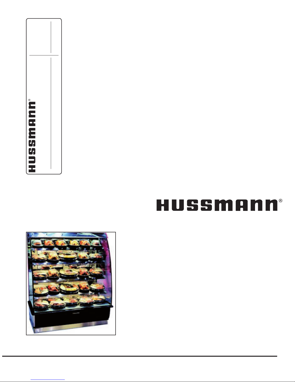
This Booklet Contains Information on:
HED HOT CASES
Self Service Hot cases designed to t within a lineup of
multidec self service cases or at the end of a lineup.
Shipping Damage
All equipment should be thoroughly examined for shipping
damage before and during unloading.
This equipment has been carefully inspected at our factory
and the carrier has assumed responsibility for safe arrival.
If damaged, either apparent or concealed, claim must be
made to the carrier.
Apparent Loss or Damage
If there is an obvious loss or damage, it must be noted on
the freight bill or express receipt and signed by the carrier’s
agent; otherwise, carrier may refuse claim. The carrier will
supply necessary claim forms.
Concealed Loss or Damage
When loss or damage is not apparent until after equipment
is uncrated, a claim for concealed damage is made. Make
request in writing to carrier for inspection within 15 days,
and retain all packaging. The carrier will supply inspection
report and required claim forms.
Shortages
Check your shipment for any possible shortages of
material. If a shortage should exist and is found to be the
responsibility of Hussmann Chino, notify Hussmann Chino.
If such a shortage involves the carrier, notify the carrier
immediately, and request an inspection. Hussmann Chino
will acknowledge shortages within ten days from receipt
of equipment.
Hussmann Chino Product Control
The serial number and shipping date of all equipment
has been recorded in Hussmann’s les for warranty and
replacement part purposes. All correspondence pertaining
to warranty or parts ordering must include the serial number
of each piece of equipment involved, in order to provide
the customer with the correct parts.
Keep this booklet with the case at all times for future reference.
/CHINO
A publication of HUSSMANN® Chino
13770 Ramona Avenue • Chino, California 91710
(909) 628-8942 FAX
(909) 590-4910
(800) 395-9229
2
Page 3
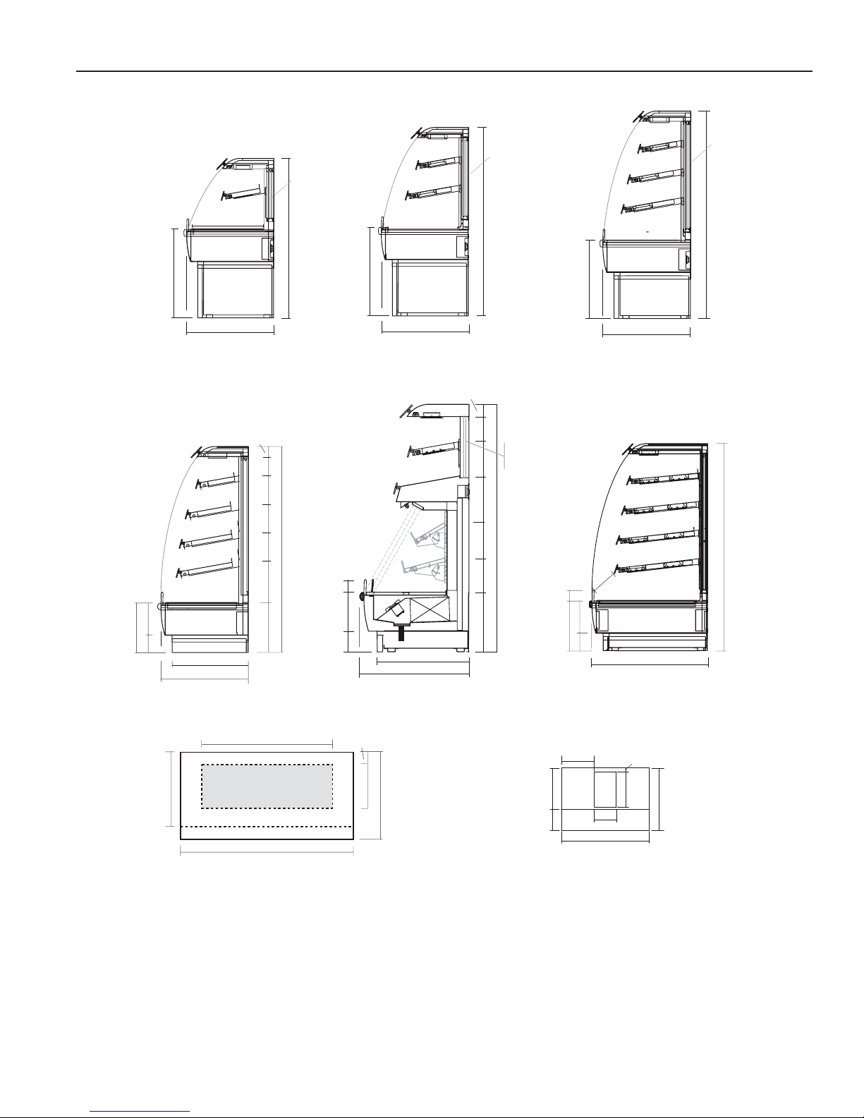
Rev. 0508
3"
HEDN-03
Scale 1/2"
53"
9
1
/
2
"
247/8"
25"
11
1
/
2
"
203/8"
Optional
rear doors
HEDN-02
Scale 1/2"
247/8"
45"
25"
9
1
/
2
"
211/4"
Optional
rear doors
9
1
/
2
"
11
1
/
2
"
203/8"
13
1
/
2
"
22"
58"
247/8"
HEDN-04
Scale 1/2"
Optional
rear doors
HEDN-05
Scale = 1/2"
3"
14
1
/
2
"
8"8"8"11
3
/
4
"
58"
9
1
/
2
"
11
1
/
2
"
13
1
/
2
"
203/8"
9"
14"
247/8"
21
3
/4"
5"
2
7
/
4
"
5
3
/8"
14"
Shown
with
optional
rear doors
48"
(VARIABLE LENGTHS)
24
7
/
8
"
12
7
/
8
"
36"
21
3
/
4
"
3
3
/
4
"
HEDN
Plan View
Scale = 1/2"
MECHANICAL CONNECTION AREA
12 7/8" X 21 3/4"
Front of Case
8"
1
0
"
HEDN-05 COMBO
Hot Over Cold Self Service
Scale = 1/2"
247/8"
213/4"
8"
58"
9"
3"5"
9
1
/
2
"
12
1
/
4
"
171/8"
8
1
/
4
"8
1
/
8
"
5
5
/
8
"
3
1
/
4
"
14"
Hot
Section
Cold
Section
Optional
Rear
Doors
58"
1
8
1
/
2
"
1
9
1
/
2
"
20
1
/
2
"
20
1
/
2
"
271/2"
HEDW-05
Hot Self Service End Display
Scale = 1/2"
323/4"
7
1
/
2
"
14"
9"5"
3"
HEDW
Plan View
Scale = 1/4"
19"
22
1
/
4
"
Elec.
Stub-
Up
Area
19"x12"
11
1
/
2
"
33
3
/
4
"
48"
(VARIABLE LENGTHS)
18"
2"
12"
Cut and Plan Views
3
Page 4
Installation
TO AVOID REMOVING CONCRETE FLOORING, BEGIN
LINEUP LEVELING FROM THE HIGHEST POINT OF
THE STORE FLOOR.
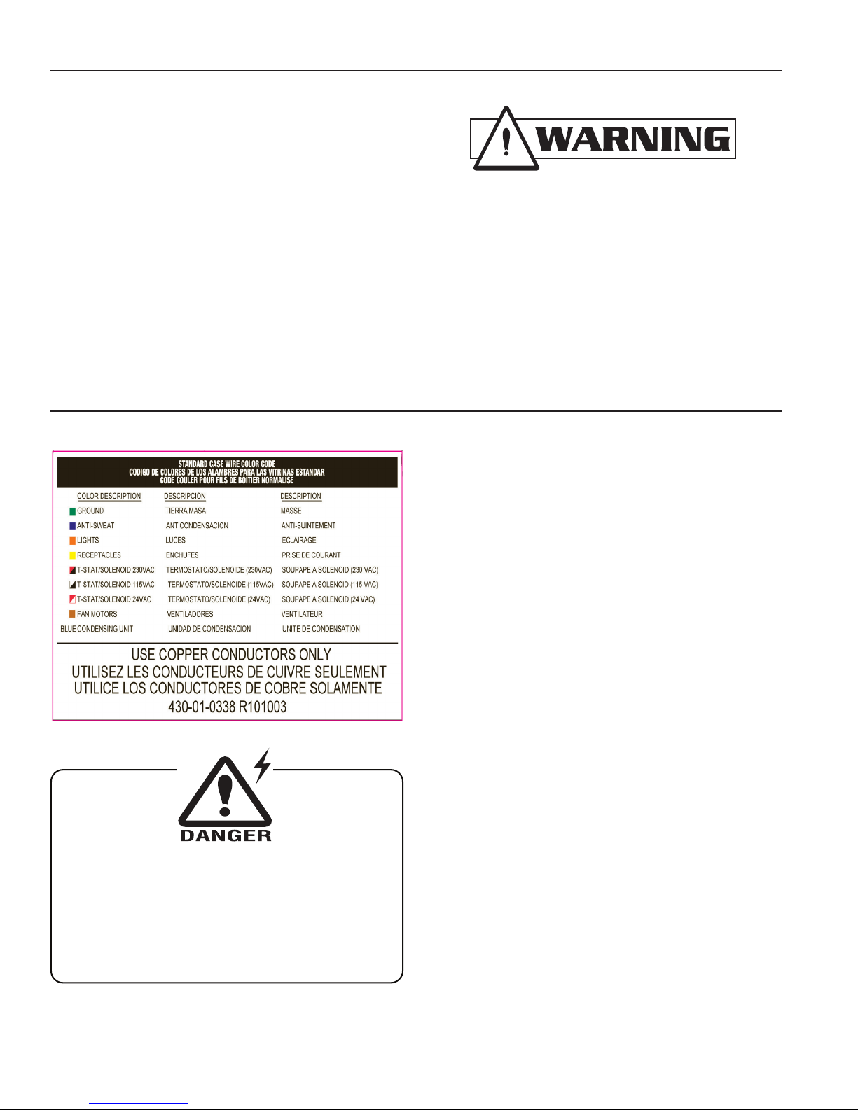
BEFORE SERVICING
ALWAYS DISCONNECT ELECTRICAL
POWER AT THE MAIN DISCONNECT
WHEN SERVICING OR REPLACING ANY
ELECTRICAL COMPONENT.
This includes (but not limited to) Heaters and Lights.
IMPORTANT! IT IS IMPERATIVE THAT CASES BE
LEVELED FROM FRONT TO BACK AND SIDE TO SIDE
PRIOR TO JOINING. A LEVEL CASE IS NECESSARY
TO INSURE PROPER OPERATION, WATER DRAINAGE,
GLASS ALIGNMENT, AND OPERATION OF THE HINGES
SUPPORTING THE GLASS. LEVELING THE CASE
CORRECTLY WILL SOLVE MOST HINGE OPERATION
PROBLEMS.
ALL CASES WERE LEVELED AND JOINED
PRIOR TO SHIPMENT, TO INSURE THE CLOSEST
POSSIBLE FIT WHEN CASES ARE JOINED IN THE
FIELD.
Electrical
Wiring Color Code
CASE MUST BE GROUNDED
IGHT-HEDN, HEDN COMBO, HEDW-0508
Leveling/Joining Instructions
Check oor where cases are to be set to see if it’s level.
Determine where the highest part of the oor is. Cases will
be shimmed off this point. Using case blueprints, measure
off and mark on oor the exact dimensions of the case
footprint. Snap chalk line for front and back position of
base rail. Mark location of each joint front and back. Use
a transit to nd the highest point along both lines. Mark
the difference, and place the appropriate number of shims
required to maintain high - point level.
Electrical Circuit Identication
Standard lighting for all models will be full length uorescent
lamps located within the case at the top. The switch
controlling the lights, the plug provided for digital scale,
and the thermometer are located at the rear of the case
mullion.
The receptacle that is provided on the exterior back of these
models is intended for computerized scales with a ve amp
maximum load, not for large motors or other high wattage
appliances. It should be wired to a dedicated circuit.
Electrical Service Receptacles
(When Applicable)
The receptacles located on the exterior of the merchandiser
are intended for scales and lighted displays. They are not
intended nor suitable for large motors or other external
appliances.
Field Wiring and Serial Plate Amperage
Field Wiring must be sized for component amperes printed
on the serial plate. Actual ampere draw may be less than
specied. Most component amperes are listed in the “Wiring
Diagram” section, but always check the serial plate.
Ballast Location
Ballasts are located within the access panel that runs the
length of the rear of the case. Refer to diagram.
4
Page 5
Rev. 0508
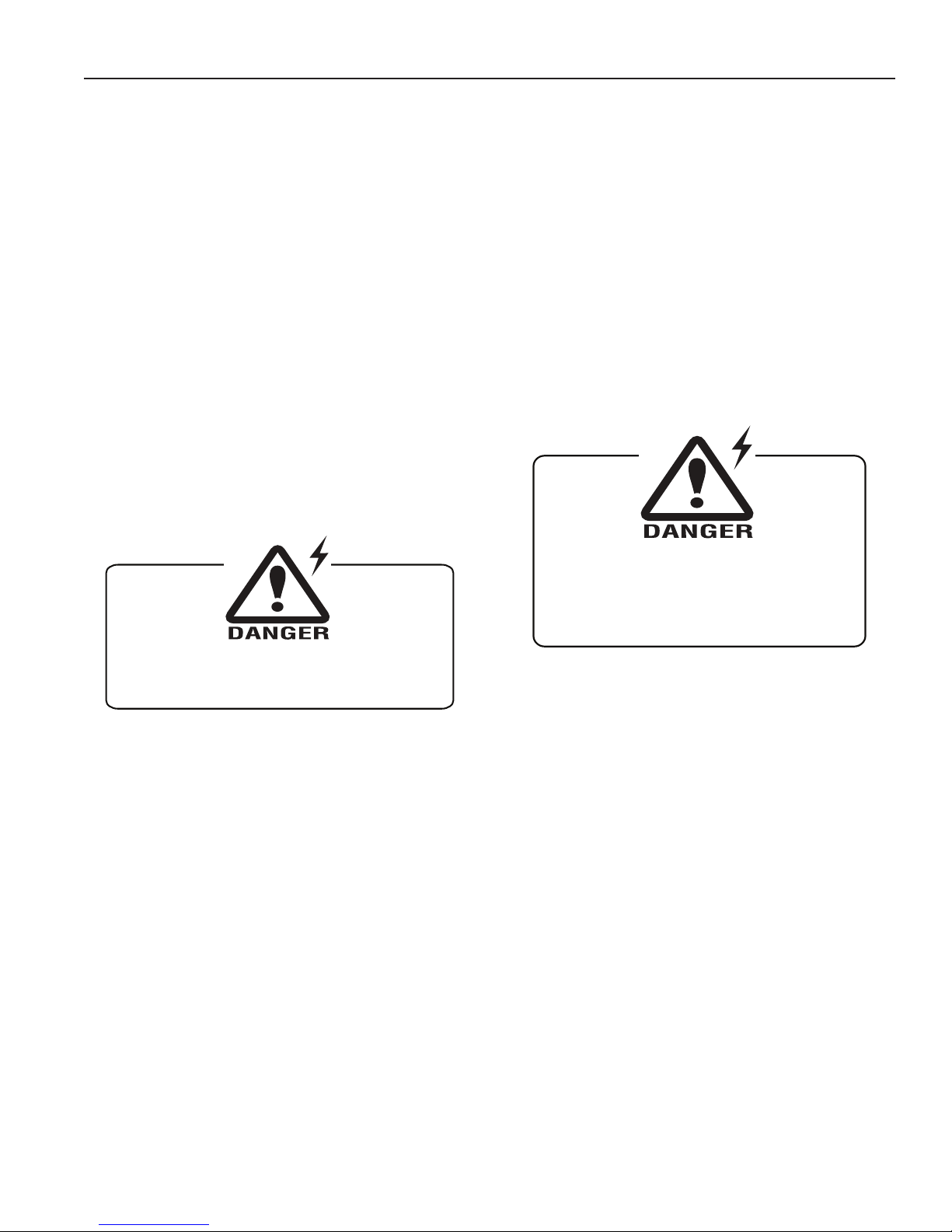
The case metal and the light bulbs become
extremely hot when in use.
DO NOT Touch Hot Case or Lights With bare hands!
DO NOT FLOOD!
Use only enough solution necessary to clean
surface. Water must not drip down the case!
Never use ammonia based cleansers, abrasive
cleansers, or scouring pads.
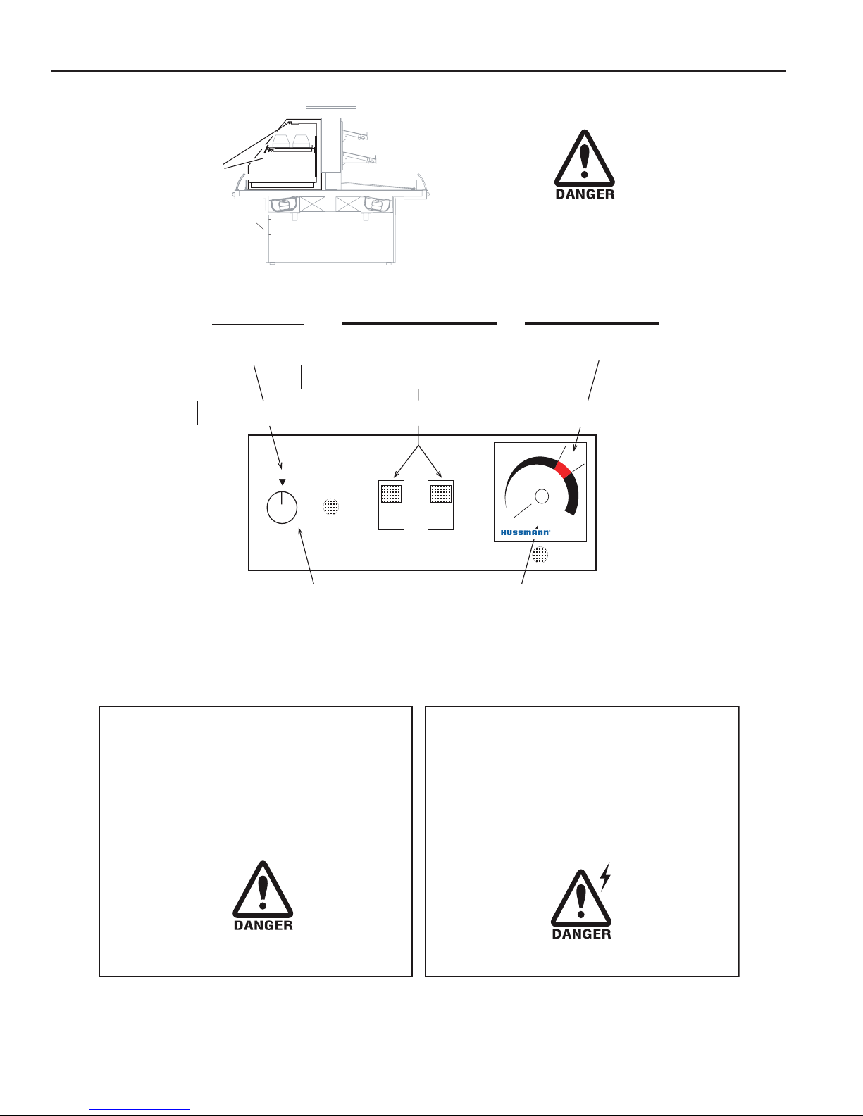
Operation
Controls
Pictured on the following page is an HED-02 with the
appropriate controls. All the HED’s have the same controls,
however, as the number of shelves and case lengths vary,
the number of these controls does also. Each is clearly
labeled on the control panel on the back of the case.
Daily Startup
1. Check to make sure All switches are starting in the
"OFF" position
2. Flip O/H Light switches to "ON" position. When
toggle switch is ipped to "on" position, the light to
the left of the on off toggle switches will go on. If it
does not, turn the toggle switch to the off position
and tell your maintenance department the case is
not getting power.
3. Turn shelf light dial (on left hand side) to "5". Light
next to dial will cycle on when the unit is heating, and
cycle off when it has reached temperature.
4. Turn shelf warmer dial (on right hand side) to "7".
The light next to the dial will cycle on when the
unit is heating, and cycle off when it has reached
temperature.
Operation Tips
1. Check the food to make sure the temperature is
correct. Hot foods should be held at a minimum of
140°F.
2. When restocking case, rotate older product to front
of case, load newer product in the back.
3. Clean spills as soon as they occur to avoid baked on
food soil.
Shut-down and Cleaning
1. Unload product from case.
2. Turn the dials for the Overhead Lights and the
Griddle Heat control to the "OFF" position.
3. Allow the case to cool for at least 30-45 minutes
before cleaning.
4. Clean the decks of the case with a mild soapy
solution and a sponge.
5. Wait an hour before loading pre - heated product*.
*These cases are not designed to cook or heat - up
food. Food must be at 150°-160°F BEFORE loading
into the case. Check food temperature with a
thermometer before putting in case.
6. After one hour, measure the product temperature by
using a food thermometer.
7. Adjust if necessary, increase or decrease
(whichever is appropriate) both dials, one number
at a time until the desired temperature has been
reached. Measure the product temperature with
a thermometer an hour after re - setting the case
temperature.
5. Wipe soap residue off with a sponge and clear,
clean water. Using caution not to put too much water
on the shelf.
6. Dry with clean towel or paper towel.
7. Polish and clean glass with a good glass cleaner.
5
Page 6
HED-02
Two Level Display
1. Measure PRODUCT temperature hourly by inserting a food thermometer into the food. Proper holding temperature is 140°.
2. To change temperature, increase or decrease Overhead Heat by one number at a time. Adjust the griddle temperature as
necessary. Measure product temperature again in one hour. Readjust if necessary.
ADJUST TEMPERATURE
SHUTDOWN
Operation Tips
1. Check the food temperature frequently with a thermometer
to make sure it is proper holding temperature.
Hot foods should be held at 140°.
2. Do not display more food than will be sold within a 4 hour
period.
3. When restocking, bring older food to front, stock fresher
food in back.
4. Clean spills as soon as they happen.
5. Oils and splatter will drastically shorten bulb life.
DANGER OF ELECTRICAL SHOCK OR CASE DAMAGE
USE THE MINIMUM AMOUNT OF LIQUID WHEN CLEANING!
Parts of the case exterior, shelves and light
bulbs become extremely hot when in use.
DO NOT
Touch Hot Case or Lights with
bare hands!
Nightly Cleaning
1. Turn case off and unload product.
2. Allow the case to cool for at least 30-45 minutes.
3. Clean the shelves and deck with a mild cleaning solution
and sponge. Never use ammonia based cleansers, abrasive
cleansers, or scouring pads.
WRING OUT CLOTH /
SPONGE THOROUGHLY BEFORE CLEANING!
4. Wipe residue off with a sponge and clear, clean water.
5. Dry with clean cotton or paper towel.
6. Polish and clean glass with a good glass cleaner
Control Panel
on Rear of Case
1. Turn all switches and dials to "OFF" position.
2. Allow case to cool and clean.
O/H HEAT
LIGHT
LO HI
6
5
4
3
2
ON / OFF
OFF
ON / OFF
OVERHEADHEAT
INITIAL
SETTING
"5"
OVERHEAD LIGHTS ON / OFF
TURN
SWITCHES
ON
GRIDDLE TEMPERA
TURE
INITIAL
SETTING
"7"
Check to make sure all lights come on at start-up.
If they do not contact your Service Department
Allow case preheat for 45 minutes prior to loading
NOTE: This equipment is not designed to heat-up or cook food. Food must be 150° - 160° when put in display.
CONTROL PANEL
GRIDDLE
OVERHEAD HEAT & LAMPS
Parts of the case exterior, shelves and light
bulbs become extremely hot when in use.
USE EXTREME CAUTION!
START-UP
©
HUSSMANN Corp. Chino, California HED Oper Lable/Est r00/05 dmd
430-01-0365 9810
1
2
3
4
5
6
7
8
9
10
S
t
a
r
t
u
p
Operation (Cont'd)
IGHT-HEDN, HEDN COMBO, HEDW-0508
6
Page 7

Rev. 0508
Electrical Wiring Diagrams
HEDN-02
HEDN-03
HEDN-04
HEDN-05
Hot/Cold Combo
WITHOUT TOP SHELF
HEDW-02
HEDW-03
HEDW-04
HEDW-05
3' W6300092
4' W6300093
5' W6300094
6' W6300095
8' W6300096
3' W6300086
4' W6300097
5' W6300098
6' W6300099
8' W6300100
3' W6300101
4' W6300102
5' W6300103
6' W6300104
8' W6300084
3' W6300105
4' W6300091
4' W6300127
5' W6300106
6' W6300081
6' W6300126
8' W6300107
3' W6300108
4' W6300109
5' W6300110
6' W6300111
8' W6300112
3' W6300113
4' W6300082
5' W6300114
6' W6300115
8' W6300116
3' W6300117
4' W6300118
5' W6300119
6' W6300120
8' W6300121
3' W6300122
4' W6300083
5' W6300123
6' W6300124
8' W6300089
7
Page 8
IGHT-HEDN, HEDN COMBO, HEDW-0508
DATE:
PROJECT TITLE:
DRAWING #:
DRAWN BY:
PRODUCTION ORDER #:
DRAWING TITLE:
DATE:
Hussmann Corporation, Int'l.
13770 Ramona Avenue
Chino, CA. 91710
(909)-590-4910 Lic.#: 644406
REVISIONS:
#: DESCRIPTION:
CHECKED BY:
BY:
FILE LOCATION:
Mark Cipriani
PAGE OF
?
1
1
01/09/06
A REVISED RATINGS; ADDED SHEET 2 4/10/07 JR
B Updated dwg: removed sheet 2; added limiter 3/3/08 JR
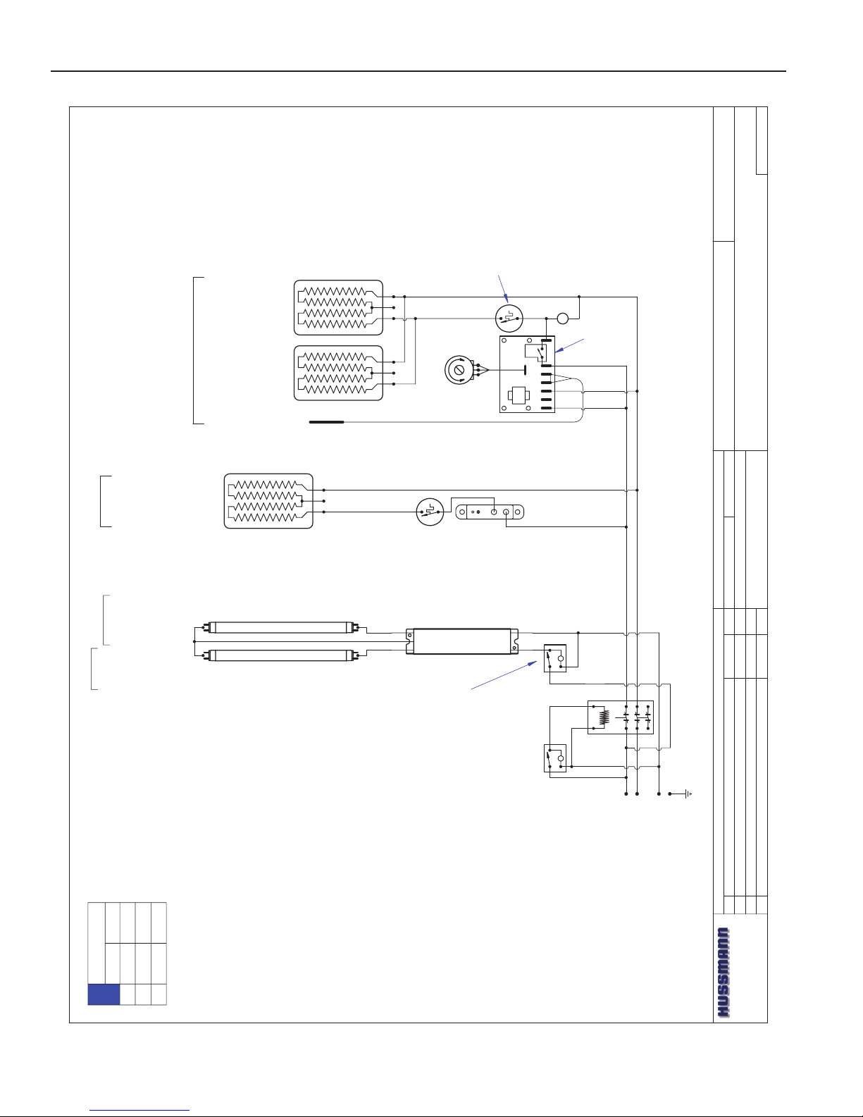
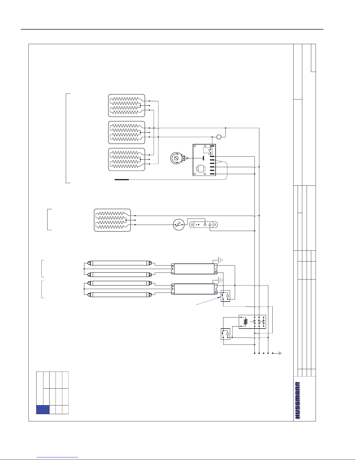
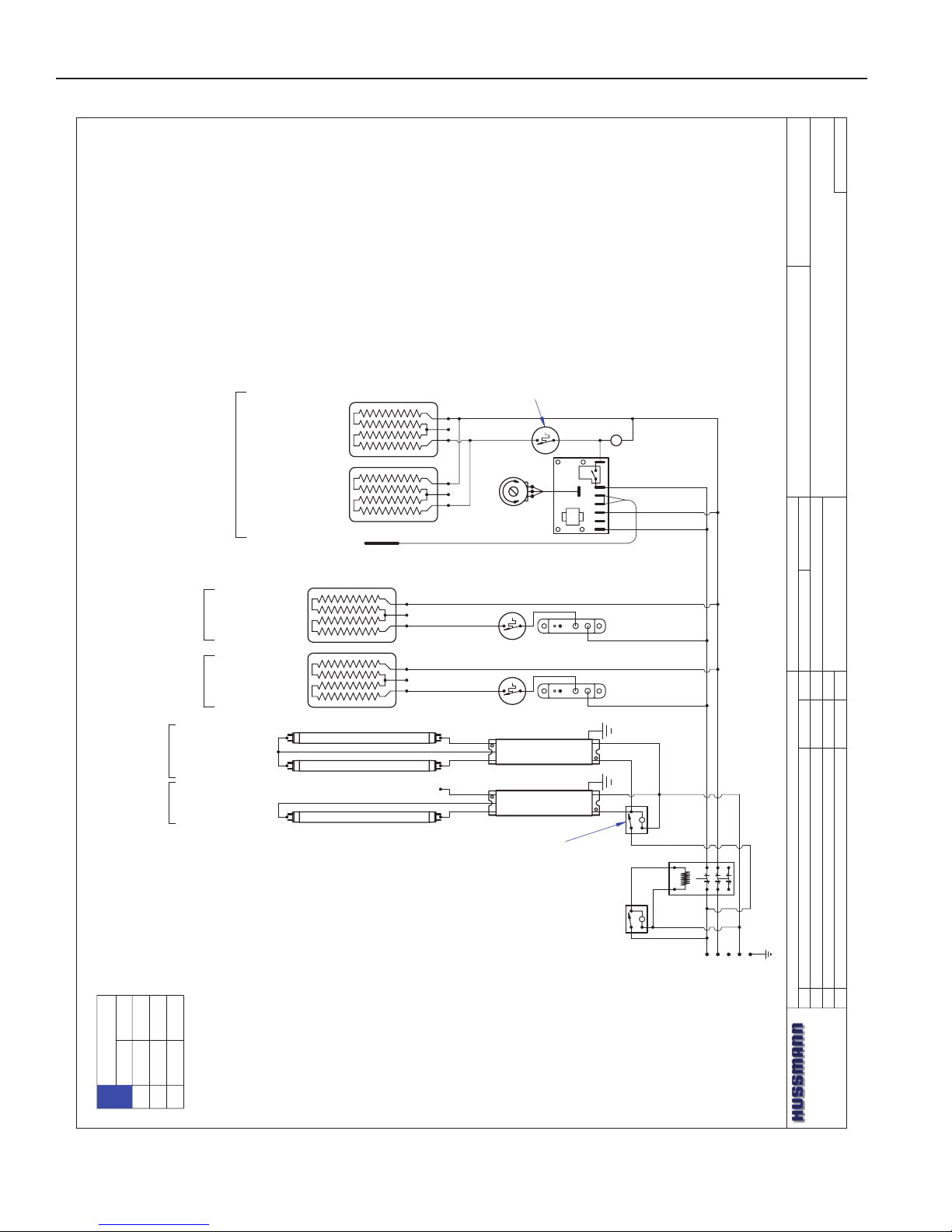
HEDN-02
W6300092
3' CASE WIRING DIAGRAM
BALLAST 125-01-3267
FULHAM LH4-120-L
L
LIGHT SWITCH
TIPPETTE
125-01-0311
L
MAIN
POWER
~208 / ~240 VAC - 50/60 HZ
SWITCH
125-01-0311
225-01-6950
8.6x33.7
473 WATTS
1.97 AMPS @ 240 VAC
THERMOSTAT
TEMPCO
TEB33000
225-01-1700
LIMIT SWITCH
TEMPCO TST-112-119
225-01-1702
PACKTRONICS
CONTROLLER
225-01-3229
L
TEMP. CONTROL
6
4
2
1 5
P1
3 7
SENSOR
225-01-3228
225-01-6787T
19x18
342W
1.43 AMPS @ ~240VAC
GRIDDLE-#2-Bottom
225-01-6786T
11x18
198W
0.83 AMPS @ ~240VAC
SHELF- #1 -9.5"-TOP
CONTACTOR
SQUARE -D
8910DPA43V02
125-01-1001
PILOT LIGHT
175-01-1102C
L1
L2
N
G
BLACK # 14
RED # 14
WHITE # 14
SHELF LIGHTING
(1) FP21T5/830 3'
125-03-1130
SHELF
CANOPY
OVERHEAD LIGHTING
(1) FP21T5/830 3'
125-03-1130
LIMIT SWITCH
TEMPCO TST-112-119
225-01-1702
LIGHT CIRCUIT= .39A 42W
GRN # 14
LOADING
208 V 240 V
L1
L2
4.1
3.7
4.6
4.2
NOTE:
CASE MUST
BE GROUNDED
1104W @ 240VAC
853W @ 208VAC
Wiring Diagrams
8
Page 9

Rev. 0508
DATE:
PROJECT TITLE:
DRAWING #:
DRAWN BY:
PRODUCTION ORDER #:
DRAWING TITLE:
DATE:
Hussmann Corporation, Int'l.
13770 Ramona Avenue
Chino, CA. 91710
(909)-590-4910 Lic.#: 644406
REVISIONS:
#: DESCRIPTION:
CHECKED BY:
BY:
FILE LOCATION:
JESSE RIOS
---
PAGE OF1
1
4/19/07
B Updated dwg; added 225-01-1702 to griddle 1/28/08 JR
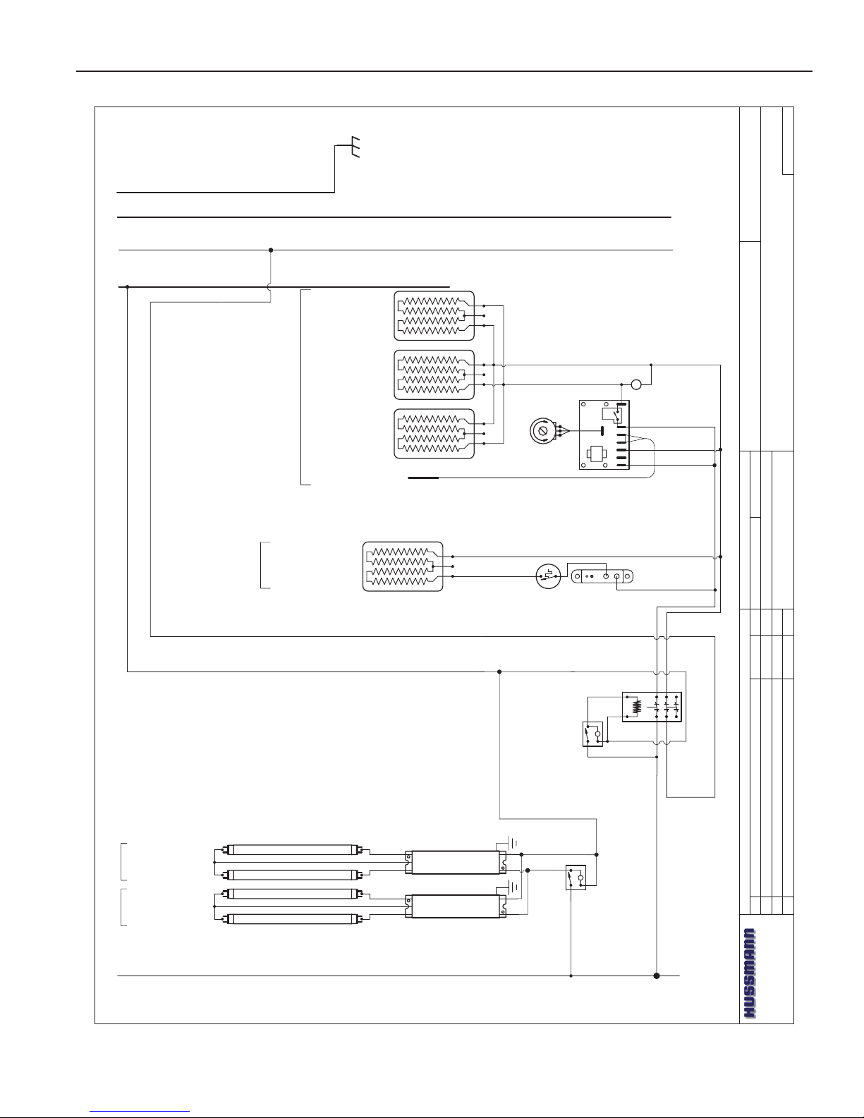
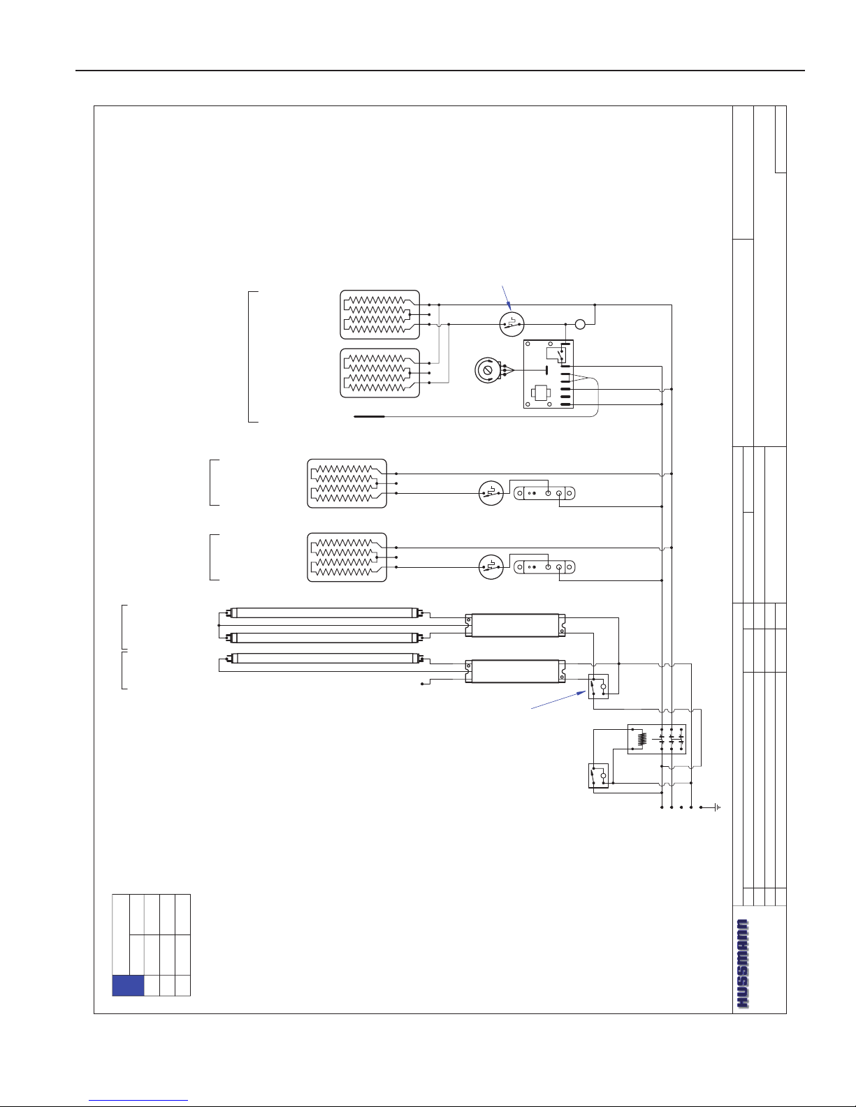
HEDN-02
W6300093
4' CASE WIRING DIAGRAM
BALLAST 125-01-3267
FULHAM LH4-120-L
LL
~208 / ~240 VAC - 50/60 HZ
SWITCH
125-01-0311
225-01-6787T
19x18
342WATTS
1.43AMPS @ 240 VAC
225-01-6787T
19x18
342WATTS
1.43AMPS @ 240 VAC
GRIDDLE-#2-Bottom
PACKTRONICS
CONTROLLER
225-01-3229
L
TEMP. CONTROL
SENSOR
225-01-3228
6
421 5
P1
3 7
PILOT LIGHT
175-01-1102C
225-01-6954
8.6x45.7
642 WATTS
2.68 AMPS @ 240 VAC
THERMOSTAT
TEMPCO
TEB33000
225-01-1700
LIMIT SWITCH
TEMPCO TST-112-119
225-01-1702
SHELF- #1 -9.5"-TOP
LIGHT SWITCH
TIPPETTE
125-01-0311
CONTACTOR
SQUARE -D
8910DPA43V02
125-01-1001
15 AMP FUSE
125-01-3282
FUSE HOLDER
125-01-3283
SHELF
CANOPY
OVERHEAD LIGHTING
(1) FP28T5/830 4'
125-03-1133
SHELF LIGHTING
(1) FP28T5/830 4'
125-03-1133
L1
L2
N
G
LIGHT CIRCUIT= 56W.52A
BLK # 14
RED # 14
WHT # 14
LIMIT SWITCH
TEMPCO TST-112-119
225-01-1702
LOADING
208 V 240 V
L1
L2
L3
5.3
4.8
6.1
5.5
NOTE:
CASE MUST
BE GROUNDED
1382W @ 240VAC
1054W @ 208VAC
Wiring Diagrams (Cont'd)
9
Page 10
DATE:
PROJECT TITLE:
DRAWING #:
DRAWN BY:
PRODUCTION ORDER #:
DRAWING TITLE:
DATE:
Hussmann Corporation, Int'l.
13770 Ramona Avenue
Chino, CA. 91710
(909)-590-4910 Lic.#: 644406
REVISIONS:
#: DESCRIPTION:
CHECKED BY:
BY:
FILE LOCATION:
PAGE OF1
2
4/19/07
HEDN-02
W6300094
5' CASE WIRING DIAGRAM
BALLAST 125-01-3267
FULHAM LH4-120-L
L
L
~208 / ~240 VAC - 3Ø - 50/60 HZ
SWITCH
125-01-0311
225-01-6958
8.6x57.7
810 WATTS
3.38 AMPS @ 240 VAC
SHELF- #1 -9.5"-TOP
225-01-6787T
19.0x18.0
342 WATTS
1.43 AMPS @ 240 VAC
225-01-6786T
11.0x18.0
198 WATTS
0.83 AMPS @ 240 VAC
225-01-6787T
19.0x18.0
342 WATTS
1.43 AMPS @ 240 VAC
PILOT LIGHT
125-01-1102C
LIGHT SWITCH
TIPPETTE
125-01-0311
15 AMP FUSE
125-01-3282
FUSE HOLDER
125-01-3283
CONTACTOR
SQUARE -D
8910DPA43V02
125-01-1001
PACKTRONICS
CONTROLLER
225-01-3229
L
TEMP. CONTROL
SENSOR
225-01-3228
6421 5
P1
3 7
THERMOSTAT
TEMPCO
TEB33000
225-01-1700
LIMIT SWITCH
TEMPCO TST-112-119
225-01-1702
GRIDDLE-#2-Bottom
OVERHEAD LIGHTING
(1) FP35T5/830 5'
125-03-1136
SHELF LIGHTING
(2) FP14T5/830 2'
125-03-1127
SHELF
CANOPY
BALLAST 125-01-3267
FULHAM LH4-120-L
CAP UNUSED RED LEAD
LIGHT CIRCUIT= .53A
L1L2L3
N
G
BLK # 14
RED # 14
WHT # 14
JESSE RIOS
LOADING
208 V 240 V
L1
L2
L3
6.7
6.1
7.6
7.1
NOTE:
CASE MUST
BE GROUNDED
Wiring Diagrams (Cont'd)
IGHT-HEDN, HEDN COMBO, HEDW-0508
10
Page 11
Rev. 0508
DATE:
PROJECT TITLE:
DRAWING #:
DRAWN BY:
PRODUCTION ORDER #:
DRAWING TITLE:
DATE:
Hussmann Corporation, Int'l.
13770 Ramona Avenue
Chino, CA. 91710
(909)-590-4910 Lic.#: 644406
REVISIONS:
#: DESCRIPTION:
CHECKED BY:
BY:
FILE LOCATION:
PAGE OF2
2
4/19/07
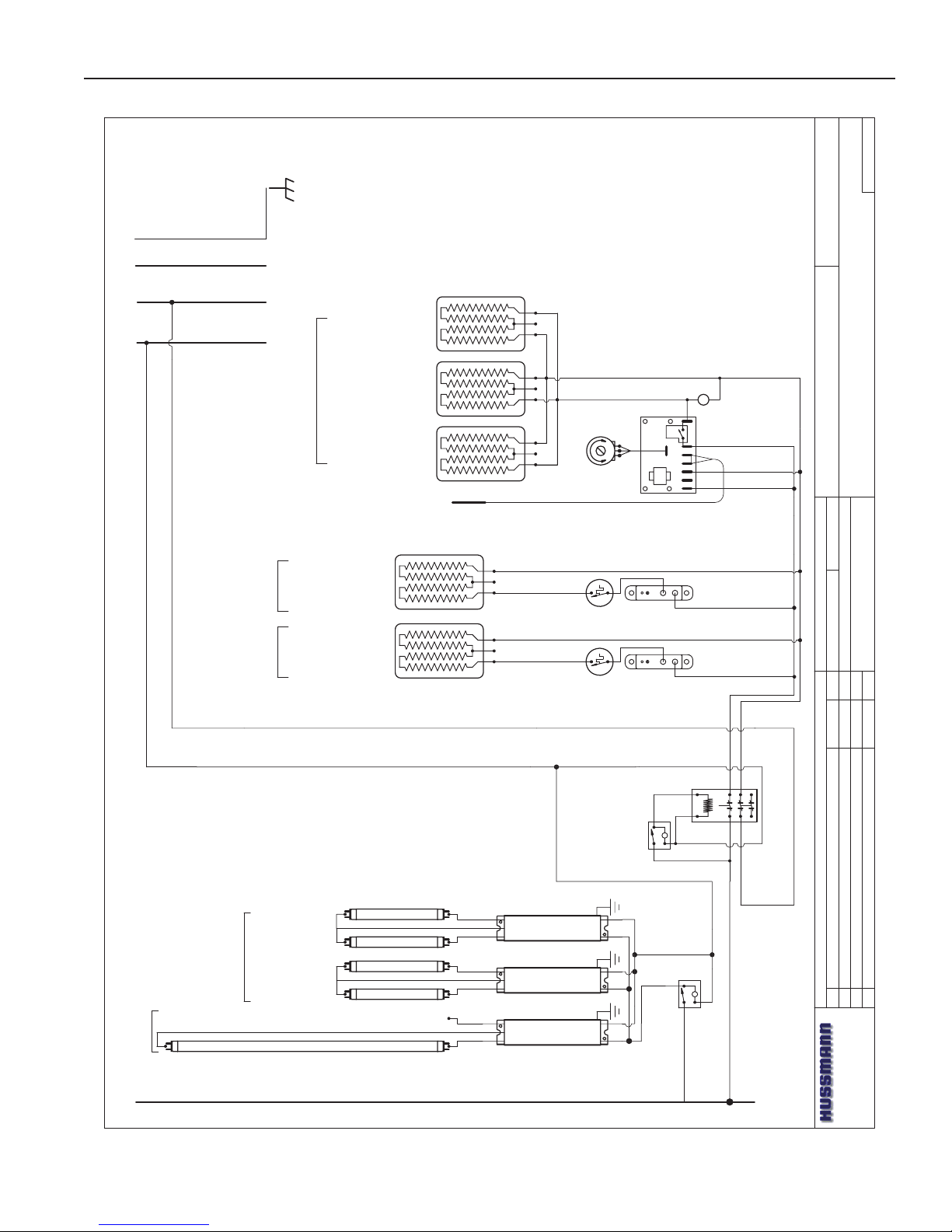
HEDN-02
W6300094
5' CASE WIRING DIAGRAM
JESSE RIOS
L1
BLACK (BLK)
# 14
WHITE (W)
#14
N
L2
GREEN (G)
# 14
G
BK
RED (R)
# 14
L3
L
SWITCH
125-01-0311
CIRCUIT #1
BLUE
(BL)
R
BL
BLACK
WHITE
L
LIGHT SWITCH
TIPPETTE
125-01-0311
WHITE
RED
BALLAST 125-01-3267
FULHAM LH4-120-L
OVERHEAD LIGHTING
(1) FP35T5/830 5'
125-03-1136
SHELF LIGHTING
(2) FP14T5/830 2'
125-03-1127
SHELF
CANOPY
CAP UNUSED RED LEAD
LIGHT CIRCUIT= .53A
225-01-6958
8.6x57.7
810 WATTS
3.38 AMPS @ 240 VAC
SHELF- #1 -9.5"-TOP
225-01-6787T
19.0x18.0
342 WATTS
1.43 AMPS @ 240 VAC
225-01-6786T
11.0x18.0
198 WATTS
0.83 AMPS @ 240 VAC
225-01-6787T
19.0x18.0
342 WATTS
1.43 AMPS @ 240 VAC
PILOT LIGHT
125-01-1102C
PACKTRONICS
CONTROLLER
225-01-3229
L
TEMP. CONTROL
SENSOR
225-01-3228
64
21 5
P1
3 7
THERMOSTAT
TEMPCO
TEB33000
225-01-1700
LIMIT SWITCH
TEMPCO TST-112-119
225-01-1702
GRIDDLE-#2-Bottom
BALLAST 125-01-3267
FULHAM LH4-120-L
Wiring Diagrams (Cont'd)
11
Page 12
DATE:
PROJECT TITLE:
DRAWING #:
DRAWN BY:
PRODUCTION ORDER #:
DRAWING TITLE:
DATE:
Hussmann Corporation, Int'l.
13770 Ramona Avenue
Chino, CA. 91710
(909)-590-4910 Lic.#: 644406
REVISIONS:
#: DESCRIPTION:
CHECKED BY:
BY:
FILE LOCATION:
JESSE RIOS
PAGE OF
?
121
4/19/07
HEDN-02
W6300095
6' CASE WIRING DIAGRAM
LIGHT SWITCH
TIPPETTE
125-01-0311
L
SWITCH
125-01-0311
~208 / ~240 VAC - 3Ø - 50/60 HZ
L
CONTACTOR
SQUARE -D
8910DPA43V02
125-01-1001
OVERHEAD LIGHTING
(2) FP21T5/830 3'
125-03-1130
PACKTRONICS
CONTROLLER
225-01-3229
L
TEMP. CONTROL
6421 5
P1
3 7
SHELF LIGHTING
(2) FP21T5/830 3'
125-03-1130
225-01-6962
8.6x69.7
979 WATTS
4.08 AMPS @ 240 VAC
THERMOSTAT
TEMPCO
TEB33000
225-01-1700
LIMIT SWITCH
TEMPCO TST-112-119
225-01-1702
BALLAST 125-01-3267
FULHAM LH4-120-L
BALLAST 125-01-3267
FULHAM LH4-120-L
225-01-6787T
19x18
342 WATTS
1.43AMPS @ 240 VAC
GRIDDLE-#2-Bottom
SENSOR
225-01-3228
PILOT LIGHT
175-01-1102C
SHELF- #1 -9.5"-TOP
SHELVES
CANOPY
L1L2L3NG
BLK # 14
RED # 14
WHT # 14
225-01-6787T
19x18
342 WATTS
1.43AMPS @ 240 VAC
225-01-6787T
19x18
342 WATTS
1.43AMPS @ 240 VAC
LIGHT CIRCUIT= .7A
LOADING
208 V 240 V
L1
L2
L3
8.0
7.3
9.1
8.4
NOTE:
CASE MUST
BE GROUNDED
Wiring Diagrams (Cont'd)
IGHT-HEDN, HEDN COMBO, HEDW-0508
12
Page 13
Rev. 0508
DATE:
PROJECT TITLE:
DRAWING #:
DRAWN BY:
PRODUCTION ORDER #:
DRAWING TITLE:
DATE:
Hussmann Corporation, Int'l.
13770 Ramona Avenue
Chino, CA. 91710
(909)-590-4910 Lic.#: 644406
REVISIONS:
#: DESCRIPTION:
CHECKED BY:
BY:
FILE LOCATION:
JESSE RIOS
PAGE OF
?
L1
BLACK (BLK)
# 14
WHITE (W)
#14
N
L2
GREEN (G)
# 14
G
BK
RED (R)
# 14
L3
L
SWITCH
125-01-0311
CIRCUIT #1
BLUE
(BL)
R
BL
BLACK
WHITE
L
LIGHT SWITCH
TIPPETTE
125-01-0311
WHITE
RED
LIGHT CIRCUIT= .7A
OVERHEAD LIGHTING
(2) FP21T5/830 3'
125-03-1130
SHELF LIGHTING
(2) FP21T5/830 3'
125-03-1130
BALLAST 125-01-3267
FULHAM LH4-120-L
BALLAST 125-01-3267
FULHAM LH4-120-L
SHELVES
CANOPY
PACKTRONICS
CONTROLLER
225-01-3229
L
TEMP. CONTROL
6421 5
P1
3 7
225-01-6962
8.6x69.7
979 WATTS
4.08 AMPS @ 240 VAC
THERMOSTAT
TEMPCO
TEB33000
225-01-1700
LIMIT SWITCH
TEMPCO TST-112-119
225-01-1702
225-01-6787T
19x18
342 WATTS
1.43AMPS @ 240 VAC
GRIDDLE-#2-Bottom
SENSOR
225-01-3228
PILOT LIGHT
175-01-1102C
SHELF- #1 -9.5"-TOP
225-01-6787T
19x18
342 WATTS
1.43AMPS @ 240 VAC
225-01-6787T
19x18
342 WATTS
1.43AMPS @ 240 VAC
RED
HEDN-02
W6300095
6' CASE WIRING DIAGRAM
2
2
4/19/07
Wiring Diagrams (Cont'd)
13
Page 14
DATE:
PROJECT TITLE:
DRAWING #:
DRAWN BY:
PRODUCTION ORDER #:
DRAWING TITLE:
DATE:
Hussmann Corporation, Int'l.
13770 Ramona Avenue
Chino, CA. 91710
(909)-590-4910 Lic.#: 644406
REVISIONS:
#: DESCRIPTION:
CHECKED BY:
BY:
FILE LOCATION:
JESSE RIOS
---
PAGE OF1
2
4/19/07
HEDN-02
W6300096
8' CASE WIRING DIAGRAM
L
LIGHT SWITCH
TIPPETTE
125-01-0311
L
~208 / ~240 VAC - 3Ø - 50/60 HZ
SWITCH
125-01-0311
225-01-6954
8.6x45.7
642 WATTS
2.68 AMPS @ 240 VAC
THERMOSTAT
TEMPCO
TEB33000
225-01-1700
LIMIT SWITCH
TEMPCO TST-112-119
225-01-1702
225-01-6954
8.6x45.7
642 WATTS
2.68 AMPS @ 240 VAC
THERMOSTAT
TEMPCO
TEB33000
225-01-1700
LIMIT SWITCH
TEMPCO TST-112-119
225-01-1702
225-01-6787T
19x18
342WATTS
1.43AMPS @ 240 VAC
225-01-6787T
19x18
342WATTS
1.43AMPS @ 240 VAC
SENSOR
225-01-3228
225-01-6787T
19x18
342WATTS
1.43AMPS @ 240 VAC
225-01-6787T
19x18
342WATTS
1.43AMPS @ 240 VAC
SENSOR
225-01-3228
OVERHEAD LIGHTING
(2) FP28T5/830 4'
125-03-1133
SHELF LIGHTING
(2) FP28T5/830 4'
125-03-1133
SHELVES
CANOPY
BALLAST 125-01-3267
FULHAM LH4-120-L
BALLAST 125-01-3267
FULHAM LH4-120-L
SHELF-9.5"-RIGHT-TOP
SHELF-9.5"-LEFT-TOP
GRIDDLE-RIGHT-BOTTOM
GRIDDLE-LEFT-BOTTOM
642
1 5
P1
3 7
TEMP. CONTROL
L
PACKTRONICS
CONTROLLER
225-01-3229
PILOT LIGHT
175-01-1102C
64
2
1 5
P1
3 7
TEMP. CONTROL
L
PACKTRONICS
CONTROLLER
225-01-3229
PILOT LIGHT
175-01-1102C
CONTACTOR
SQUARE -D
8910DPA43V02
125-01-1001
LIGHT CIRCUIT= .93A
L1
L2
L3NG
BLK # 14
RED # 14
WHT # 14
LOADING
208 V 240 V
L1
L2
L3
9.9
9.0
12.0
11.1
NOTE:
CASE MUST
BE GROUNDED
Wiring Diagrams (Cont'd)
IGHT-HEDN, HEDN COMBO, HEDW-0508
14
Page 15
Rev. 0508
DATE:
PROJECT TITLE:
DRAWING #:
DRAWN BY:
PRODUCTION ORDER #:
DRAWING TITLE:
DATE:
Hussmann Corporation, Int'l.
13770 Ramona Avenue
Chino, CA. 91710
(909)-590-4910 Lic.#: 644406
REVISIONS:
#: DESCRIPTION:
CHECKED BY:
BY:
FILE LOCATION:
JESSE RIOS
---
PAGE OF2
2
4/19/07
HEDN-02
W6300096
8' CASE WIRING DIAGRAM
L1
BLACK (BLK)
# 14
WHITE (W)
#14
N
L2
GREEN (G)
# 14
G
BK
RED (R)
# 14
L3
L
SWITCH
125-01-0311
CIRCUIT #1
BLUE
(BL)
BLACK
WHITE
L
LIGHT SWITCH
TIPPETTE
125-01-0311
WHITE
RED
RED
225-01-6954
8.6x45.7
590 WATTS
2.46 AMPS @ 240 VAC
THERMOSTAT
TEMPCO
TEB33000
225-01-1700
LIMIT SWITCH
TEMPCO TST-112-119
225-01-1702
225-01-6954
8.6x45.7
590 WATTS
2.46 AMPS @ 240 VAC
225-01-6787T
19x18
342WATTS
2.30AMPS @ 240 VAC
225-01-6787T
19x18
342WATTS
2.30AMPS @ 240 VAC
SENSOR
225-01-3228
225-01-6787T
19x18
342WATTS
2.30AMPS @ 240 VAC
225-01-6787T
19x18
342WATTS
2.30AMPS @ 240 VAC
SENSOR
225-01-3228
SHELF-9.5"-RIGHT-TOP
SHELF-9.5"-LEFT-TOP
GRIDDLE-RIGHT-BOTTOM
GRIDDLE-LEFT-BOTTOM
6421 5
P1
3 7
TEMP. CONTROL
L
PACKTRONICS
CONTROLLER
225-01-3229
PILOT LIGHT
175-01-1102C
6421 5
P1
3 7
TEMP. CONTROL
L
PACKTRONICS
CONTROLLER
225-01-3229
PILOT LIGHT
175-01-1102C
THERMOSTAT
TEMPCO
TEB33000
225-01-1700
LIMIT SWITCH
TEMPCO TST-112-119
225-01-1702
OVERHEAD LIGHTING
(2) FP28T5/830 4'
125-03-1133
SHELF LIGHTING
(2) FP28T5/830 4'
125-03-1133
SHELVES
CANOPY
BALLAST 125-01-3267
FULHAM LH4-120-L
LIGHT CIRCUIT= .93A
BALLAST 125-01-3267
FULHAM LH4-120-L
Wiring Diagrams (Cont'd)
15
Page 16
IGHT-HEDN, HEDN COMBO, HEDW-0508
DATE:
PROJECT TITLE:
DRAWING #:
DRAWN BY:
PRODUCTION ORDER #:
DRAWING TITLE:
DATE:
Hussmann Corporation, Int'l.
13770 Ramona Avenue
Chino, CA. 91710
(909)-590-4910 Lic.#: 644406
REVISIONS:
#: DESCRIPTION:
CHECKED BY:
BY:
FILE LOCATION:
JESSE RIOS
PAGE OF
?
1
1
4/20/07
1
B Updated dwg; added 225-01-1702 to griddle 1/28/07 JR
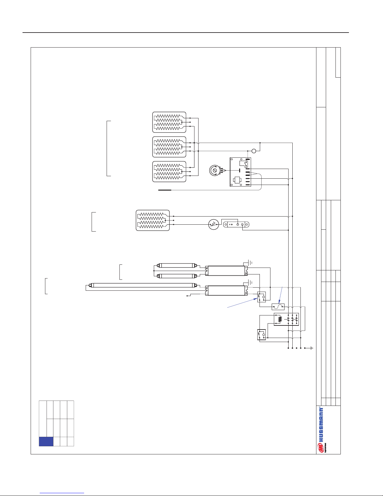
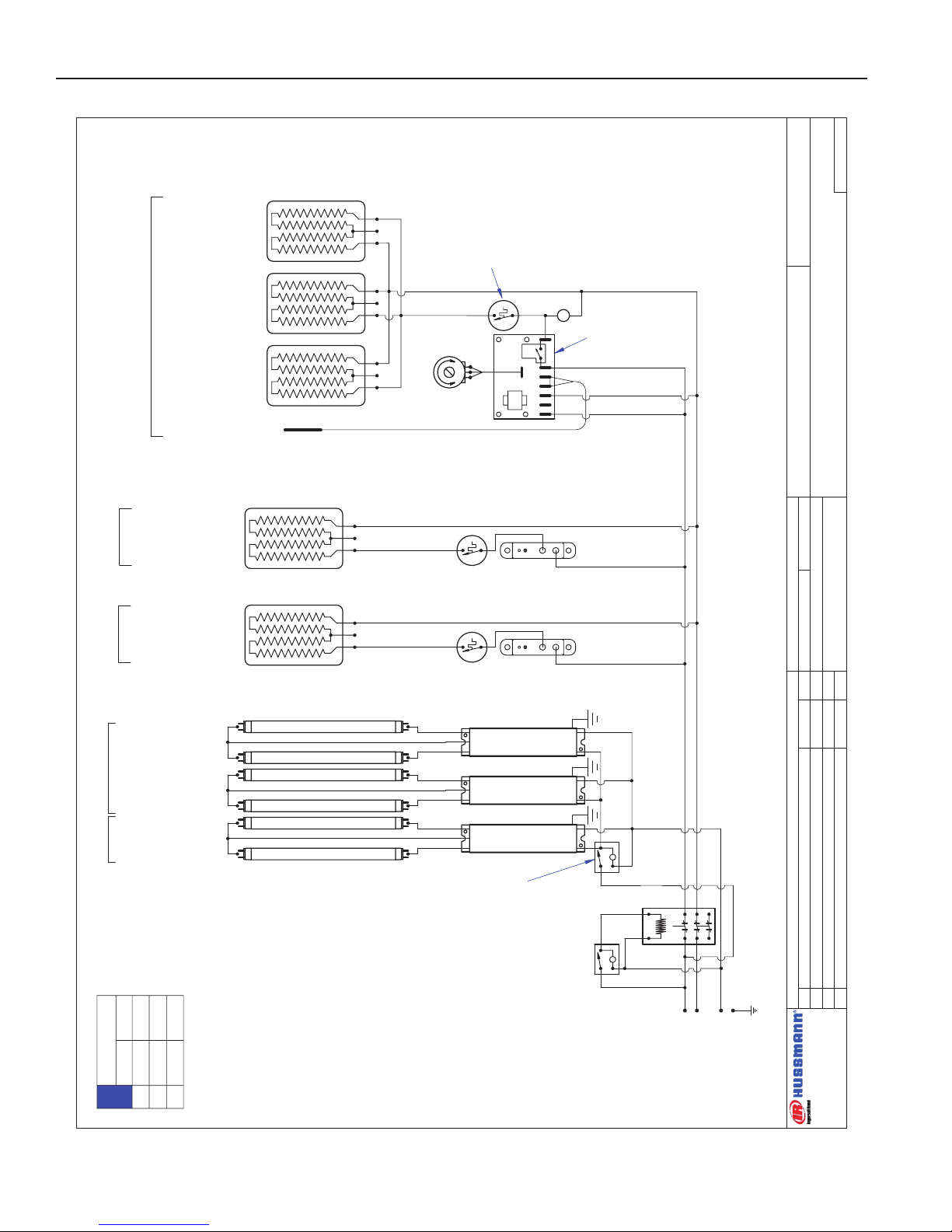
HEDN-03
W6300086
3' CASE WIRING DIAGRAM
L
L
MAIN
POWER
~208 / ~240 VAC - 3Ø - 50/60 HZ
SWITCH
125-01-0311
BALLAST 125-01-3267
FULHAM LH4-120-L
BALLAST 125-01-3267
FULHAM LH4-120-L
225-01-6950
8.6x33.7
473 WATTS
1.97 AMPS @ 240 VAC
225-01-6951
10.6x33.7
583 WATTS
2.43AMPS @ 240 VAC
THERMOSTAT
TEMPCO
TEB33000
225-01-1700
LIMIT SWITCH
TEMPCO TST-112-119
225-01-1702
THERMOSTAT
TEMPCO
TEB33000
225-01-1700
LIMIT SWITCH
TEMPCO TST-112-119
225-01-1702
PACKTRONICS
CONTROLLER
225-01-3229
L
TEMP. CONTROL
SENSOR
225-01-3228
6421
5
P1
3 7
LIGHT SWITCH
TIPPETTE
125-01-0311
CONTACTOR
SQUARE -D
8910DPA43V02
125-01-1001
PILOT LIGHT
175-01-1102C
SHELF- #1 -9.5"-TOP
SHELF- #2 -11.5"
GRIDDLE-#3-Bottom
225-01-6787T
19.0x18.0
342 WATTS
1.43 AMPS @ 240 VAC
225-01-6786T
11.0x18.0
198 WATTS
0.83 AMPS @ 240 VAC
CAP UNUSED RED LEAD
OVERHEAD LIGHTING
FP21T5/830 3'
125-03-1130
SHELF LIGHTING
(2) FP21T5/830 3'
125-03-1130
SHELVES
CANOPY
L1
L2
L3
N
G
LIGHT CIRCUIT= .58A 63W
BLK # 14
RED # 14
WHT # 14
LIMIT SWITCH
TEMPCO TST-112-119
225-01-1702
NOTE:
CASE MUST
BE GROUNDED
7.2
6.7
6.4
5.8
L1
L2
208 V 240 V
LOADING
1659W @ 240VAC
1264W @ 208VAC
Wiring Diagrams (Cont'd)
16
Page 17
Rev. 0508
DATE:
PROJECT TITLE:
DRAWING #:
DRAWN BY:
PRODUCTION ORDER #:
DRAWING TITLE:
DATE:
Hussmann Corporation, Int'l.
13770 Ramona Avenue
Chino, CA. 91710
(909)-590-4910 Lic.#: 644406
REVISIONS:
#: DESCRIPTION:
CHECKED BY:
BY:
FILE LOCATION:
JESSE RIOS
PAGE OF
?
111
4/20/07
B Updated dwg; added limiter to griddle circuit 3/19/08 JR
HEDN-03
W6300097
4' CASE WIRING DIAGRAM
BALLAST 125-01-3267
FULHAM LH4-120-L
LL
~208 / ~240 VAC - 50/60 HZ
SWITCH
125-01-0311
BALLAST 125-01-3267
FULHAM LH4-120-L
225-01-6954
8.6x45.7
642 WATTS
2.68 AMPS @ 240 VAC
THERMOSTAT
TEMPCO
TEB33000
225-01-1700
LIMIT SWITCH
TEMPCO TST-112-119
225-01-1702
225-01-6955
10.6x45.7
791 WATTS
3.30 AMPS @ 240 VAC
THERMOSTAT
TEMPCO
TEB33000
225-01-1700
LIMIT SWITCH
TEMPCO TST-112-119
225-01-1702
225-01-6787T
19x18
342WATTS
1.43 AMPS @ 240 VAC
225-01-6787T
19x18
342WATTS
1.43 AMPS @ 240 VAC
GRIDDLE-#3-Bottom
PACKTRONICS
CONTROLLER
225-01-3229
L
TEMP. CONTROL
SENSOR
225-01-3228
6421 5
P1
3 7
SHELF- #1 -9.5"-TOP
SHELF- #2 -11.5"
PILOT LIGHT
175-01-1102C
CAP UNUSED RED LEAD
LIGHT SWITCH
TIPPETTE
125-01-0311
CONTACTOR
SQUARE -D
8910DPA43V02
125-01-1001
OVERHEAD LIGHTING
(1) FP28T5/830 4'
125-03-1133
SHELF LIGHTING
(2) FP28T5/830 4'
125-03-1133
SHELVES
CANOPY
LIGHT CIRCUIT=.78 A 84W
BLK # 14
RED # 14
WHT # 14
L1L2L3
N
G
LIMIT SWITCH
TEMPCO TST-112-119
225-01-1702
LOADING
208 V 240 V
L1
L2
8.4
7.7
9.5
8.8
NOTE:
CASE MUST
BE GROUNDED
2280W @ 240VAC
1747W @ 208VAC
Wiring Diagrams (Cont'd)
17
Page 18

IGHT-HEDN, HEDN COMBO, HEDW-0508
DATE:
PROJECT TITLE:
DRAWING #:
DRAWN BY:
PRODUCTION ORDER #:
DRAWING TITLE:
DATE:
Hussmann Corporation, Int'l.
13770 Ramona Avenue
Chino, CA. 91710
(909)-590-4910 Lic.#: 644406
REVISIONS:
#: DESCRIPTION:
CHECKED BY:
BY:
FILE LOCATION:
JESSE RIOS
PAGE OF
?
11 2
4/20/07
HEDN-03
W6300098
5' CASE WIRING DIAGRAM
BALLAST 125-01-3267
FULHAM LH4-120-L
L
L
~208 / ~240 VAC - 3Ø - 50/60 HZ
SWITCH
125-01-0311
BALLAST 125-01-3267
FULHAM LH4-120-L
CAP UNUSED RED LEAD
225-01-6959
10.6x57.7
999 WATTS
4.17 AMPS @ 240 VAC
THERMOSTAT
TEMPCO
TEB33000
225-01-1700
LIMIT SWITCH
TEMPCO TST-112-119
225-01-1702
225-01-6958
8.6x57.7
810 WATTS
3.38 AMPS @ 240 VAC
THERMOSTAT
TEMPCO
TEB33000
225-01-1700
LIMIT SWITCH
TEMPCO TST-112-119
225-01-1702
SHELF LIGHTING
(2) FP14T5/830 2'
125-03-1127
SHELF- #1 -9.5"-TOP
SHELF- #2 -11.5"
GRIDDLE-#3-Bottom
225-01-6787T
19.0x18.0
342 WATTS
1.43 AMPS @ 240 VAC
225-01-6786T
11.0x18.0
198 WATTS
0.83 AMPS @ 240 VAC
225-01-6787T
19.0x18.0
342 WATTS
1.43 AMPS @ 240 VAC
PACKTRONICS
CONTROLLER
225-01-3229
PILOT LIGHT
125-01-1102C
L
TEMP. CONTROL
SENSOR
225-01-3228
642
1 5
P1
3 7
LIGHT SWITCH
TIPPETTE
125-01-0311
CONTACTOR
SQUARE -D
8910DPA43V02
125-01-1001
OVERHEAD LIGHTING
(1) FP35T5/830 5'
125-03-1136
SHELVES
CANOPY
BALLAST 125-01-3267
FULHAM LH4-120-L
SHELF LIGHTING
(2) FP14T5/830 2'
125-03-1127
LIGHT CIRCUIT=.76 A
BLK # 14
RED # 14
WHT # 14
L1L2L3NG
LOADING
208 V 240 V
L1
L2
L3
10.5
9.7
12.0
11.2
NOTE:
CASE MUST
BE GROUNDED
Wiring Diagrams (Cont'd)
18
Page 19
Rev. 0508
DATE:
PROJECT TITLE:
DRAWING #:
DRAWN BY:
PRODUCTION ORDER #:
DRAWING TITLE:
DATE:
Hussmann Corporation, Int'l.
13770 Ramona Avenue
Chino, CA. 91710
(909)-590-4910 Lic.#: 644406
REVISIONS:
#: DESCRIPTION:
CHECKED BY:
BY:
FILE LOCATION:
JESSE RIOS
PAGE OF
?
L1
BLACK (BLK)
# 14
WHITE (W)
#14
N
L2
GREEN (G)
# 14
G
BK
RED (R)
# 14
L3
L
SWITCH
125-01-0311
BLUE
(BL)
BLACK
WHITE
L
LIGHT SWITCH
TIPPETTE
125-01-0311
WHITE
RED
RED
225-01-6959
10.6x57.7
999 WATTS
4.17 AMPS @ 240 VAC
225-01-6958
8.6x57.7
810 WATTS
3.38 AMPS @ 240 VAC
THERMOSTAT
TEMPCO
TEB33000
225-01-1700
LIMIT SWITCH
TEMPCO TST-112-119
225-01-1702
SHELF- #1 -9.5"-TOP
SHELF- #2 -11.5"
GRIDDLE-#3-Bottom
225-01-6787T
19.0x18.0
342 WATTS
1.43 AMPS @ 240 VAC
225-01-6786T
11.0x18.0
198 WATTS
0.83 AMPS @ 240 VAC
225-01-6787T
19.0x18.0
342 WATTS
1.43 AMPS @ 240 VAC
PACKTRONICS
CONTROLLER
225-01-3229
PILOT LIGHT
125-01-1102C
L
TEMP. CONTROL
SENSOR
225-01-3228
642
1 5
P1
3 7
THERMOSTAT
TEMPCO
TEB33000
225-01-1700
LIMIT SWITCH
TEMPCO TST-112-119
225-01-1702
BALLAST 125-01-3267
FULHAM LH4-120-L
BALLAST 125-01-3267
FULHAM LH4-120-L
CAP UNUSED RED LEAD
SHELF LIGHTING
(2) FP14T5/830 2'
125-03-1127
OVERHEAD LIGHTING
(1) FP35T5/830 5'
125-03-1136
SHELVES
CANOPY
BALLAST 125-01-3267
FULHAM LH4-120-L
SHELF LIGHTING
(2) FP14T5/830 2'
125-03-1127
LIGHT CIRCUIT=.76 A
2 2
4/20/07
HEDN-03
W6300098
5' CASE WIRING DIAGRAM
Wiring Diagrams (Cont'd)
19
Page 20
IGHT-HEDN, HEDN COMBO, HEDW-0508
DATE:
PROJECT TITLE:
DRAWING #:
DRAWN BY:
PRODUCTION ORDER #:
DRAWING TITLE:
DATE:
Hussmann Corporation, Int'l.
13770 Ramona Avenue
Chino, CA. 91710
(909)-590-4910 Lic.#: 644406
REVISIONS:
#: DESCRIPTION:
CHECKED BY:
BY:
FILE LOCATION:
JESSE RIOS
---
PAGE OF1
1
4/20/07
B Updated dwg; removed sheet 2; added limiter to griddle 3/17/08 JR
HEDN-03
W6300099
6' CASE - WIRING DIAGRAM
PACKTRONICS
CONTROLLER
225-01-3229
L
TEMP. CONTROL
6421 5
P1
3 7
LIGHT SWITCH
TIPPETTE
125-01-0311
L
SWITCH
125-01-0311
~208 / ~240 VAC - 50/60 HZ
L
CONTACTOR
SQUARE -D
8910DPA43V02
125-01-1001
225-01-6963
10.6x69.7
1207 WATTS
5.03 AMPS @ 240 VAC
THERMOSTAT
TEMPCO
TEB33000
225-01-1700
LIMIT SWITCH
TEMPCO TST-112-119
225-01-1702
225-01-6962
8.6x69.7
979 WATTS
4.08 AMPS @ 240 VAC
THERMOSTAT
TEMPCO
TEB33000
225-01-1700
LIMIT SWITCH
TEMPCO TST-112-119
225-01-1702
BALLAST 125-01-3267
FULHAM LH4-120-L
BALLAST 125-01-3267
FULHAM LH4-120-L
BALLAST 125-01-3267
FULHAM LH4-120-L
PILOT LIGHT
175-01-1102C
225-01-6787T
19x18
342WATTS
1.43 AMPS @ 240 VAC
225-01-6787T
19x18
342WATTS
1.43 AMPS @ 240 VAC
GRIDDLE-#3-Bottom
SENSOR
225-01-3228
225-01-6787T
19x18
342WATTS
1.43 AMPS @ 240 VAC
SHELF- #1 -9.5"-TOP
SHELF- #2 -11.5"
OVERHEAD LIGHTING
(2) FP21T5/830 3'
125-03-1130
SHELF LIGHTING
(2) FP21T5/830 3'
125-03-1130
SHELVES
CANOPY
SHELF LIGHTING
(2) FP21T5/830 3'
125-03-1130
BLK # 14
RED # 14
WHT # 14
L1
L2
N
G
LIMIT SWITCH
TEMPCO TST-112-119
225-01-1702
LIGHT CIRCUIT= 1.17A 126W
LOADING
208 V 240 V
L1
L2
12.7
11.6
14.5
13.4
NOTE:
CASE MUST
BE GROUNDED
Wiring Diagrams (Cont'd)
20
Page 21
Rev. 0508
DATE:
PROJECT TITLE:
DRAWING #:
DRAWN BY:
PRODUCTION ORDER #:
DRAWING TITLE:
DATE:
Hussmann Corporation, Int'l.
13770 Ramona Avenue
Chino, CA. 91710
(909)-590-4910 Lic.#: 644406
REVISIONS:
#: DESCRIPTION:
CHECKED BY:
BY:
FILE LOCATION:
JESSE RIOS
---
PAGE OF1
1
4/20/07
B Add limiters to griddle circuits; revised wiring scheme 4/ 1/2008 JR
HEDN-03
W6300100
8' CASE WIRING DIAGRAM
L
LIGHT SWITCH
TIPPETTE
125-01-0311
L
~208 / ~240 VAC - 50/60 HZ
SWITCH
125-01-0311
225-01-6954
8.6x45.7
642 WATTS
2.68 AMPS @ 240 VAC
THERMOSTAT
TEMPCO
TEB33000
225-01-1700
LIMIT SWITCH
TEMPCO TST-112-119
225-01-1702
225-01-6955
10.6x45.7
791 WATTS
3.30 AMPS @ 240 VAC
THERMOSTAT
TEMPCO
TEB33000
225-01-1700
LIMIT SWITCH
TEMPCO TST-112-119
225-01-1702
225-01-6954
8.6x45.7
642 WATTS
2.68 AMPS @ 240 VAC
THERMOSTAT
TEMPCO
TEB33000
225-01-1700
LIMIT SWITCH
TEMPCO TST-112-119
225-01-1702
225-01-6955
10.6x45.7
791 WATTS
3.30 AMPS @ 240 VAC
THERMOSTAT
TEMPCO
TEB33000
225-01-1700
LIMIT SWITCH
TEMPCO TST-112-119
225-01-1702
BALLAST 125-01-3267
FULHAM LH4-120-L
BALLAST 125-01-3267
FULHAM LH4-120-L
BALLAST 125-01-3267
FULHAM LH4-120-L
OVERHEAD LIGHTING
(2) FP28T5/830 4'
125-03-1133
SHELF LIGHTING
(2) FP28T5/830 4'
125-03-1133
SHELVES
CANOPY
SHELF LIGHTING
(2) FP28T5/830 4'
125-03-1133
SENSOR
225-01-3228
6
4
2
1 5
P1
3 7
TEMP. CONTROL
L
PACKTRONICS
CONTROLLER
225-01-3229
PILOT LIGHT
175-01-1102C
SHELF-9.5"-LEFT-TOP
SHELF-11.5"-LEFT
SHELF-9.5"-RIGHT-TOP
SHELF-11.5"-RIGHT
225-01-6787T
19x18
342WATTS
1.43 AMPS @ 240 VAC
SENSOR
225-01-3228
GRIDDLE-RIGHT-BOTTOM
6
4
2
1 5
P1
3 7
TEMP. CONTROL
L
PACKTRONICS
CONTROLLER
225-01-3229
PILOT LIGHT
175-01-1102C
225-01-6787T
19x18
342 WATTS
1.43 AMPS @ 240 VAC
SENSOR
225-01-3228
GRIDDLE-LEFT-BOTTOM
6
421 5
P1
3 7
TEMP. CONTROL
L
PACKTRONICS
CONTROLLER
225-01-3229
PILOT LIGHT
175-01-1102C
CONTACTOR
SQUARE -D
8910DPA43V02
125-01-1001
L1
L2L3N
G
LIGHT CIRCUIT= 1.56A 168W
BLK # 12
RED # 12
WHT # 14
BLUE # 12
225-01-6787T
19x18
342WATTS
1.43 AMPS @ 240 VAC
225-01-6787T
19x18
342 WATTS
1.43 AMPS @ 240 VAC
BLK # 12
RED # 12
BLUE # 12
GREEN # 12
BLK # 14
LIMIT SWITCH
TEMPCO TST-112-119
225-01-1702
LIMIT SWITCH
TEMPCO TST-112-119
225-01-1702
LOADING
208 V 240 V
L1
L2
L3
11.2
10.4
10.7
12.6
12.0
12.3
NOTE:
CASE MUST
BE GROUNDED
Wiring Diagrams (Cont'd)
21
Page 22
DATE:
PROJECT TITLE:
DRAWING #:
DRAWN BY:
PRODUCTION ORDER #:
DRAWING TITLE:
DATE:
Hussmann Corporation, Int'l.
13770 Ramona Avenue
Chino, CA. 91710
(909)-590-4910 Lic.#: 644406
REVISIONS:
#: DESCRIPTION:
CHECKED BY:
BY:
FILE LOCATION:
Mark Cipriani
PAGE OF1
1
01/09/07
123
Eng\WIRESCHEMATICS\NEW-WIRING
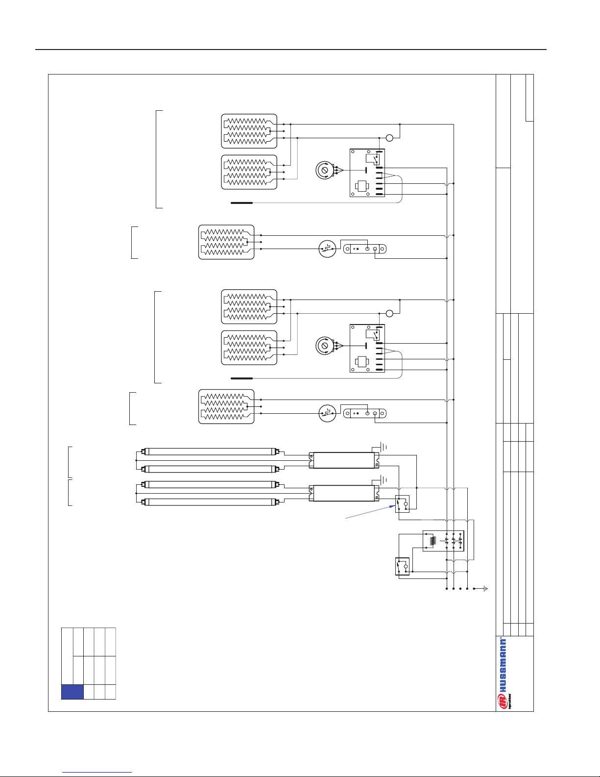
HEDN-04
W6300101
3' CASE WIRING DIAGRAM
BALLAST 125-01-3267
FULHAM LH4-120-L
L
LIGHT SWITCH
TIPPETTE
125-01-0311
L1L2L3NG
L
MAIN
POWER
~208 / ~240 VAC - 1Ø - 50/60 HZ - 4W
125-01-1001
SQUARE -D
CONTACTOR
8910DPA43V02
SWITCH
125-01-0311
CANOPY
SHELVES
BALLAST 125-01-3267
FULHAM LH4-120-L
225-01-6951
10.6x33.7
536 WATTS
2.23 AMPS @ 240 VAC
THERMOSTAT
TEMPCO
TEB33000
225-01-1700
LIMIT SWITCH
TEMPCO TST-112-119
225-01-1702
225-01-6950
8.6x33.7
435 WATTS
1.81 AMPS @ 240 VAC
THERMOSTAT
TEMPCO
TEB33000
225-01-1700
LIMIT SWITCH
TEMPCO TST-112-119
225-01-1702
225-01-6952
12.6x33.7
637 WATTS
2.65 AMPS @ 240 VAC
THERMOSTAT
TEMPCO
TEB33000
225-01-1700
LIMIT SWITCH
TEMPCO TST-112-119
225-01-1702
CASE LIGHTS
(4) FP21T5/830 3'
125-03-1130
15 AMP FUSE
125-01-3282
FUSE HOLDER
125-01-3283
PACKTRONICS
CONTROLLER
225-01-3229
PILOT LIGHT
175-01-1102C
L
TEMP. CONTROL
6421 5
P1
3 7
SENSOR
225-01-3228
225-01-6787T
19x18
342W
1.43 AMPS @ ~240VAC
GRIDDLE-#4-Bottom
225-01-6786T
11x18
198W
0.83 AMPS @ ~240VAC
SHELF- #1 -9.5"-TOP
SHELF- #2 -11.5"
SHELF- #3 -13.5"
LOADING
208 V 240 V
L1
L2
L3
9.5
7.7
~
11.0
8.9
~
NOTE:
CASE MUST
BE GROUNDED
GM
Wiring Diagrams (Cont'd)
IGHT-HEDN, HEDN COMBO, HEDW-0508
22
Page 23
Rev. 0508
DATE:
PROJECT TITLE:
DRAWING #:
DRAWN BY:
PRODUCTION ORDER #:
DRAWING TITLE:
DATE:
Hussmann Corporation, Int'l.
13770 Ramona Avenue
Chino, CA. 91710
(909)-590-4910 Lic.#: 644406
REVISIONS:
#: DESCRIPTION:
CHECKED BY:
BY:
FILE LOCATION:
ECD
PAGE OF1
1
01/17/06
B Updated dwg; added limiter to griddle circuit 4/23/08 JR
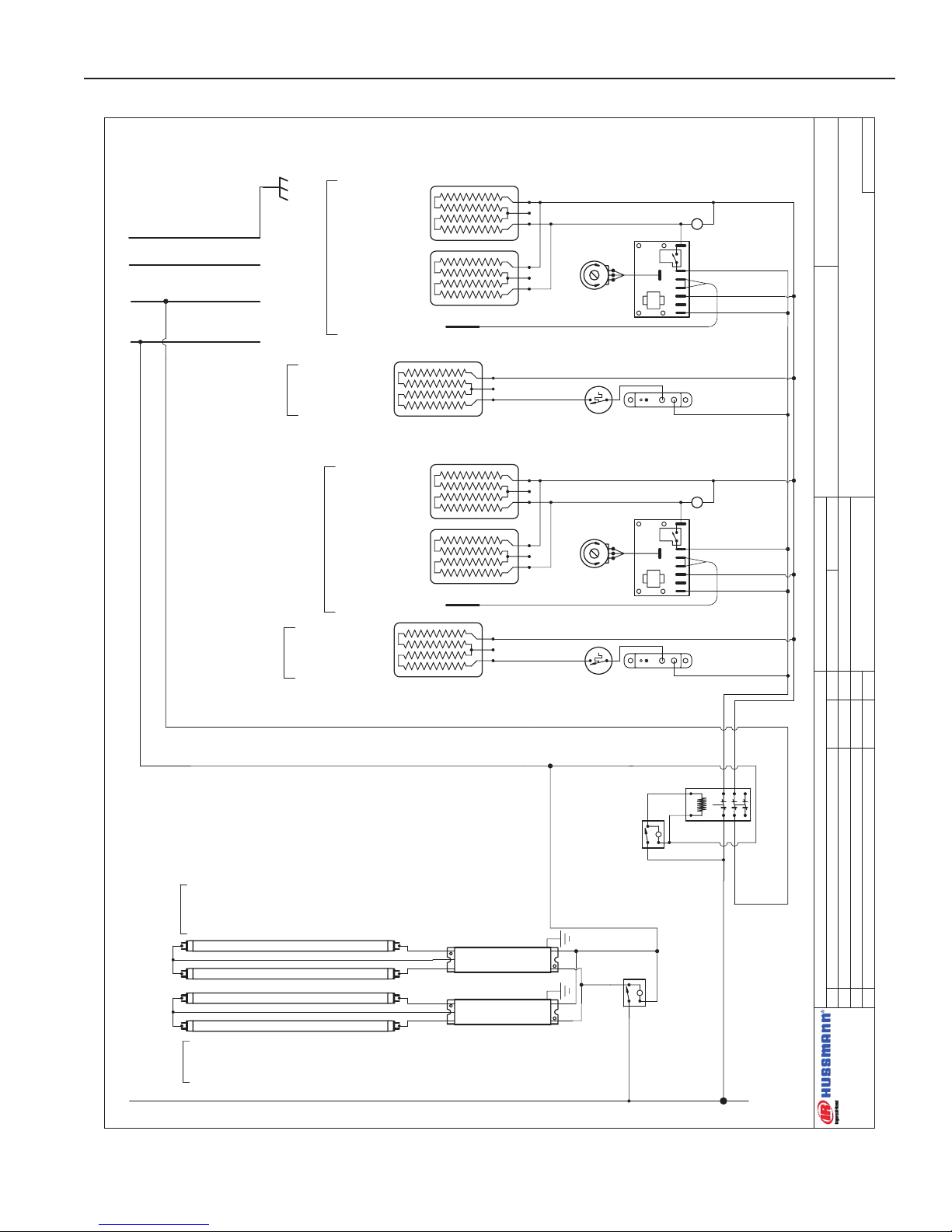
HEDN-04
W6300102
4' CASE WIRING DIAGRAM
BALLAST 125-01-3267
FULHAM LH4-120-L
L
LIGHT SWITCH
TIPPETTE
125-01-0311
L
MAIN
POWER
~208 / ~240 VAC - 50/60 HZ
125-01-1001
SQUARE -D
CONTACTOR
8910DPA43V02
SWITCH
125-01-0311
GRIDDLE HEATING PADS
(2) 342W 1.43A @ 240 VAC
225-01-6787T
BALLAST 125-01-3267
FULHAM LH4-120-L
225-01-6954
8.6x45.7
642 WATTS
2.68 AMPS @ 240 VAC
THERMOSTAT
TEMPCO
TEB33000
225-01-1700
LIMIT SWITCH
TEMPCO TST-112-119
225-01-1702
225-01-6955
10.6x45.7
791 WATTS
3.30 AMPS @ 240 VAC
THERMOSTAT
TEMPCO
TEB33000
225-01-1700
LIMIT SWITCH
TEMPCO TST-112-119
225-01-1702
225-01-6956
12.6x45.7
940 WATTS
3.92 AMPS @ 240 VAC
THERMOSTAT
TEMPCO
TEB33000
225-01-1700
LIMIT SWITCH
TEMPCO TST-112-119
225-01-1702
SHELF- #1 -9.5"-TOP
SHELF- #2 -11.5"
SHELF- #3 -13.5"
GRIDDLE-#4-Bottom
PACKTRONICS
CONTROLLER
225-01-3229
PILOT LIGHT
175-01-1102C
L
TEMP. CONTROL
SENSOR
225-01-3228
6421 5
P1
3 7
OVERHEAD LIGHTING
(1) FP28T5/830 4'
125-03-1133
SHELVES
CANOPY
OVERHEAD LIGHTING
(3) FP28T5/830 4'
125-03-1133
L1
L2NG
LIGHT CIRCUIT= 1.04A 112W
RED # 12
BLACK # 12
WHITE # 14
BLACK # 14
GREEN # 12
LIMIT SWITCH
TEMPCO TST-112-119
225-01-1702
GM
LOADING
208 V 240 V
L1
L2
12.1
11.1
13.8
12.8
NOTE:
CASE MUST
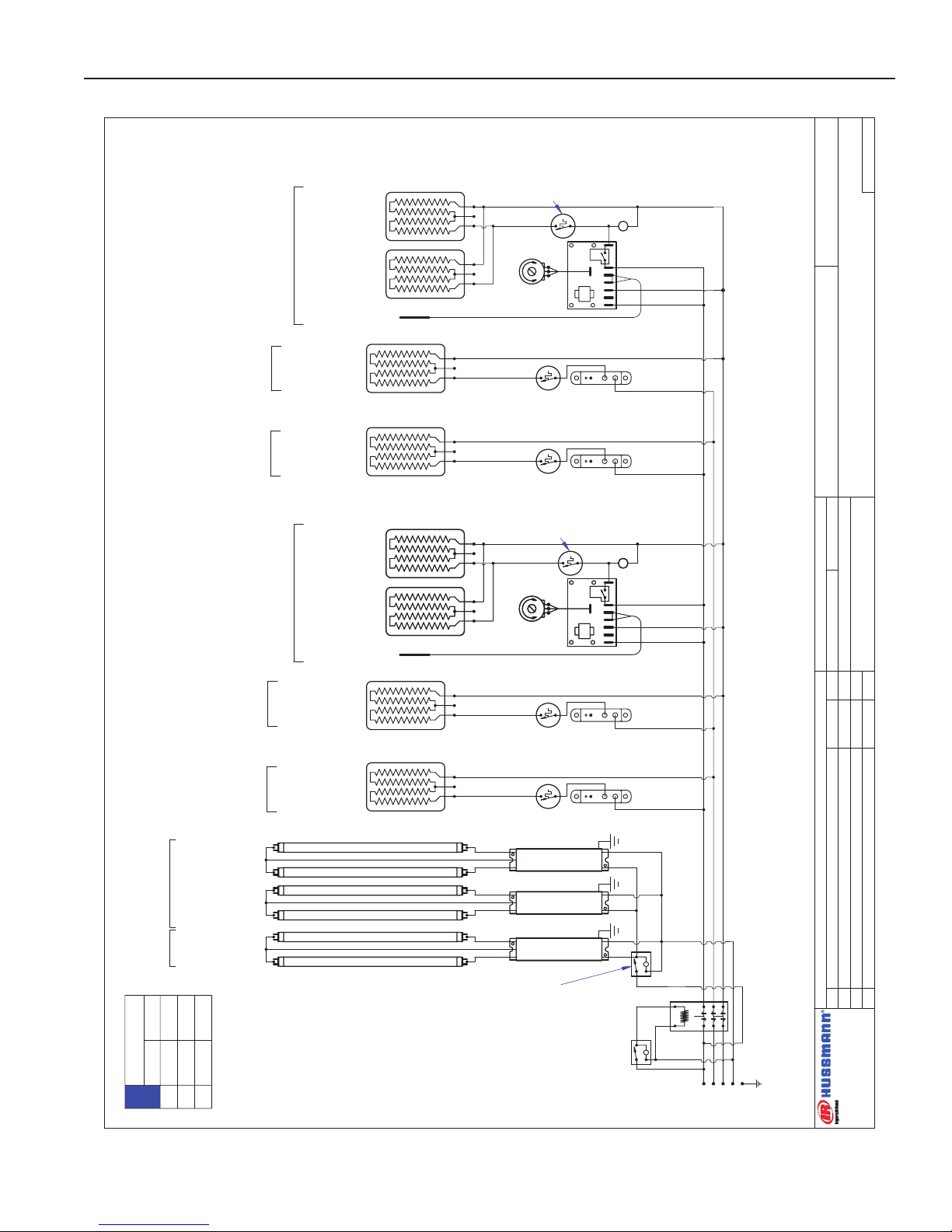
BE GROUNDED
3312W @ 240VAC
2517W @ 208VAC
Wiring Diagrams (Cont'd)
23
Page 24

DATE:
PROJECT TITLE:
DRAWING #:
DRAWN BY:
PRODUCTION ORDER #:
DRAWING TITLE:
DATE:
Hussmann Corporation, Int'l.
13770 Ramona Avenue
Chino, CA. 91710
(909)-590-4910 Lic.#: 644406
REVISIONS:
#: DESCRIPTION:
CHECKED BY:
BY:
FILE LOCATION:
JESSE RIOS
PAGE OF
?
121
4/23/07
HEDN-04
W6300103
5' CASE WIRING DIAGRAM
BALLAST 125-01-3267
FULHAM LH4-120-L
L
LIGHT SWITCH
TIPPETTE
125-01-0311
L
~208 / ~240 VAC - 50/60 HZ
SWITCH
125-01-0311
BALLAST 125-01-3267
FULHAM LH4-120-L
225-01-6960
12.6x57.7
1187 WATTS
4.95 AMPS @ 240 VAC
THERMOSTAT
TEMPCO
TEB33000
225-01-1700
LIMIT SWITCH
TEMPCO TST-112-119
225-01-1702
225-01-6959
10.6x57.7
999 WATTS
4.16 AMPS @ 240 VAC
THERMOSTAT
TEMPCO
TEB33000
225-01-1700
LIMIT SWITCH
TEMPCO TST-112-119
225-01-1702
225-01-6958
8.6x57.7
810 WATTS
3.38 AMPS @ 240 VAC
THERMOSTAT
TEMPCO
TEB33000
225-01-1700
LIMIT SWITCH
TEMPCO TST-112-119
225-01-1702
SHELF- #1 -9.5"-TOP
SHELF- #2 -11.5"
SHELF- #3 -13.5"
GRIDDLE-#4-Bottom
225-01-6787T
19.0x18.0
342 WATTS
1.43 AMPS @ 240 VAC
225-01-6786T
11.0x18.0
198 WATTS
0.83 AMPS @ 240 VAC
225-01-6787T
19.0x18.0
342 WATTS
1.43 AMPS @ 240 VAC
CONTACTOR
SQUARE -D
8910DPA43V02
125-01-1001
PACKTRONICS
CONTROLLER
225-01-3229
PILOT LIGHT
125-01-1102C
L
TEMP. CONTROL
SENSOR
225-01-3228
6
4
21 5
P1
3 7
OVERHEAD LIGHTING
(1) FP35T5/830 5'
125-03-1136
SHELVES
CANOPY
BALLAST 125-01-3267
FULHAM LH4-120-L
SHELF LIGHTING
(2) FP14T5/830 2'
125-03-1127
SHELF LIGHTING
(2) FP14T5/830 2'
125-03-1127
BALLAST 125-01-3267
FULHAM LH4-120-L
SHELF LIGHTING
(2) FP14T5/830 2'
125-03-1127
CAP UNUSED RED LEAD
L1
L2L3N
G
LIGHT CIRCUIT= 1.0A
BLK # 14
RED # 14
WHT # 14
BLUE # 14
BLK # 14
BLK # 14
RED # 14
BLUE # 14
LOADING
208 V 240 V
L1
L2
L3
10.7
10.8
7.5
12.2
12.5
8.6
NOTE:
CASE MUST
BE GROUNDED
Wiring Diagrams (Cont'd)
IGHT-HEDN, HEDN COMBO, HEDW-0508
24
Page 25

Rev. 0508
DATE:
PROJECT TITLE:
DRAWING #:
DRAWN BY:
PRODUCTION ORDER #:
DRAWING TITLE:
DATE:
Hussmann Corporation, Int'l.
13770 Ramona Avenue
Chino, CA. 91710
(909)-590-4910 Lic.#: 644406
REVISIONS:
#: DESCRIPTION:
CHECKED BY:
BY:
FILE LOCATION:
JESSE RIOS
PAGE OF
?
2
2
4/23/07
HEDN-04
W6300103
5' CASE WIRING DIAGRAM
L1
BLACK (BLK)
# 14
WHITE (W)
#14
N
L2
GREEN (G)
# 14
G
BK
RED (R)
# 14
L3
L
SWITCH
125-01-0311
BLUE
(BL)
BLACK
WHITE
L
LIGHT SWITCH
TIPPETTE
125-01-0311
WHITE
RED
RED
225-01-6960
12.6x57.7
1187 WATTS
4.95 AMPS @ 240 VAC
THERMOSTAT
TEMPCO
TEB33000
225-01-1700
LIMIT SWITCH
TEMPCO TST-112-119
225-01-1702
225-01-6959
10.6x57.7
999 WATTS
4.16 AMPS @ 240 VAC
225-01-6958
8.6x57.7
810 WATTS
3.38 AMPS @ 240 VAC
THERMOSTAT
TEMPCO
TEB33000
225-01-1700
LIMIT SWITCH
TEMPCO TST-112-119
225-01-1702
SHELF- #1 -9.5"-TOP
SHELF- #2 -11.5"
SHELF- #3 -13.5"
GRIDDLE-#4-Bottom
225-01-6787T
19.0x18.0
342 WATTS
1.43 AMPS @ 240 VAC
225-01-6786T
11.0x18.0
198 WATTS
0.83 AMPS @ 240 VAC
225-01-6787T
19.0x18.0
342 WATTS
1.43 AMPS @ 240 VAC
PACKTRONICS
CONTROLLER
225-01-3229
PILOT LIGHT
125-01-1102C
L
TEMP. CONTROL
SENSOR
225-01-3228
642
1 5
P1
3 7
THERMOSTAT
TEMPCO
TEB33000
225-01-1700
LIMIT SWITCH
TEMPCO TST-112-119
225-01-1702
BALLAST 125-01-3267
FULHAM LH4-120-L
BALLAST 125-01-3267
FULHAM LH4-120-L
OVERHEAD LIGHTING
(1) FP35T5/830 5'
125-03-1136
SHELVES
CANOPY
BALLAST 125-01-3267
FULHAM LH4-120-L
SHELF LIGHTING
(2) FP14T5/830 2'
125-03-1127
SHELF LIGHTING
(2) FP14T5/830 2'
125-03-1127
BALLAST 125-01-3267
FULHAM LH4-120-L
SHELF LIGHTING
(2) FP14T5/830 2'
125-03-1127
CAP UNUSED RED LEAD
LIGHT CIRCUIT= 1.0A
BLUE
BLUE
Wiring Diagrams (Cont'd)
25
Page 26

DATE:
PROJECT TITLE:
DRAWING #:
DRAWN BY:
PRODUCTION ORDER #:
DRAWING TITLE:
DATE:
Hussmann Corporation, Int'l.
13770 Ramona Avenue
Chino, CA. 91710
(909)-590-4910 Lic.#: 644406
REVISIONS:
#: DESCRIPTION:
CHECKED BY:
BY:
FILE LOCATION:
ECD
KM
PAGE OF1
1
02/14/07
B Updated dwg; added 225-01-1702 to griddle
1/24/08 JR
C Revised wiring scheme from 4 to 5 wire 3 phase 1/28/08 JR
D Revised load ratings per UL request 1/29/08 JR
HEDN-04
W6300104
6' CASE - WIRING DIAGRAM
PACKTRONICS
CONTROLLER
225-01-3229
PILOT LIGHT
175-01-1102C
L
TEMP. CONTROL
6421 5
P1
3 7
SENSOR
225-01-3228
LIGHT SWITCH
TIPPETTE
125-01-0311
L
SWITCH
125-01-0311
~208 / ~240 VAC - 50/60 HZ
MAIN
POWER
L
CONTACTOR
SQUARE -D
8910DPA43V02
125-01-1001
225-01-6964
12.6x69.7
1434 WATTS
5.98 AMPS @ 240 VAC
THERMOSTAT
TEMPCO
TEB33000
225-01-1700
LIMIT SWITCH
TEMPCO TST-112-119
225-01-1702
225-01-6963
10.6x69.7
1207 WATTS
5.03 AMPS @ 240 VAC
THERMOSTAT
TEMPCO
TEB33000
225-01-1700
LIMIT SWITCH
TEMPCO TST-112-119
225-01-1702
225-01-6962
8.6x69.7
979 WATTS
4.08 AMPS @ 240 VAC
THERMOSTAT
TEMPCO
TEB33000
225-01-1700
LIMIT SWITCH
TEMPCO TST-112-119
225-01-1702
225-01-6787T
19x18
342WATTS
1.43AMPS @ 240 VAC
225-01-6787T
19x18
342WATTS
1.43AMPS @ 240 VAC
GRIDDLE-#4-Bottom
225-01-6787T
19x18
342WATTS
1.43AMPS @ 240 VAC
OVERHEAD LIGHTING
(2) FP21T5/830 3'
125-03-1130
SHELF LIGHTING
(2) FP21T5/830 3'
125-03-1130
SHELVES
CANOPY
SHELF LIGHTING
(2) FP21T5/830 3'
125-03-1130
SHELF LIGHTING
(2) FP21T5/830 3'
125-03-1130
BALLAST 125-01-3267
FULHAM LH4-120-L
BALLAST 125-01-3267
FULHAM LH4-120-L
BALLAST 125-01-3267
FULHAM LH4-120-L
BALLAST 125-01-3267
FULHAM LH4-120-L
SHELF- #1 -9.5"
TOP
SHELF- #2 -11.5"
SHELF- #3 -13.5"
LIGHT CIRCUIT= 168W 1.56A
L1
L2
L3NG
BLK # 12
RED # 12
WHITE # 14
GRN # 12
BLK # 14
LIMIT SWITCH
TEMPCO TST-112-119
225-01-1702
BLUE # 12
BLK # 12
RED # 12
BLUE # 12
LOADING
208 V 240 V
L1
L2
L3
12.3
10.4
7.7
13.9
12.1
8.7
NOTE:
CASE MUST
BE GROUNDED
4814W @ 240VAC
3663W @ 208VAC
Wiring Diagrams (Cont'd)
IGHT-HEDN, HEDN COMBO, HEDW-0508
26
Page 27

Rev. 0508
DATE:
PROJECT TITLE:
DRAWING #:
DRAWN BY:
PRODUCTION ORDER #:
DRAWING TITLE:
DATE:
Hussmann Corporation, Int'l.
13770 Ramona Avenue
Chino, CA. 91710
(909)-590-4910 Lic.#: 644406
REVISIONS:
#: DESCRIPTION:
CHECKED BY:
BY:
FILE LOCATION:
JESSE RIOS
---
PAGE OF1
2
5/1/07
HEDN-04 - WITH 225-01-1700
W6300084
8' CASE - WIRING DIAGRAM
PACKTRONICS
CONTROLLER
225-01-3229
L
TEMP. CONTROL
6
4
21 5
P1
3 7
SENSOR
225-01-3228
SWITCH
125-01-0311
~208 / ~240 VAC -50/60 HZ
L
225-01-6954
8.6x45.7
642 WATTS
2.68 AMPS @ 240 VAC
L
BALLAST 125-01-3267
FULHAM LH4-120-L
225-01-6954
8.6x45.7
642 WATTS
2.68 AMPS @ 240 VAC
225-01-6955
10.6x45.7
791 WATTS
3.30 AMPS @ 240 VAC
225-01-6955
10.6x45.7
791 WATTS
3.30 AMPS @ 240 VAC
225-01-6956
12.6x45.7
940 WATTS
3.92 AMPS @ 240 VAC
225-01-6956
12.6x45.7
940 WATTS
3.92 AMPS @ 240 VAC
PACKTRONICS
CONTROLLER
225-01-3229
L
TEMP. CONTROL
6
4
2
1
5
P1
3 7
SENSOR
225-01-3228
225-01-6787T
19.0x18.0
(2) 342 WATTS
1.43 AMPS @ 240VAC
BALLAST 125-01-3267
FULHAM LH4-120-L
SHELF- #1 -9.5"
-TOP LEFT
GRIDDLE- #4 -20.5" - LEFT
SHELF- #2 -11.5"
-LEFT
SHELF- #3 -13.5"
-LEFT
SHELF- #1 -9.5"
-TOP RIGHT
SHELF- #2 -11.5"
-RIGHT
SHELF- #3 -13.5"
-RIGHT
225-01-6787T
19.0x18.0
(2) 342 WATTS
1.43 AMPS @ 240VAC
GRIDDLE- #4 -20.5" - RIGHT
BALLAST 125-01-3267
FULHAM LH4-120-L
BALLAST 125-01-3267
FULHAM LH4-120-L
OVERHEAD LIGHTING
(2) FP28T5/830 4'
125-03-1133
SHELF LIGHTING
(2) FP28T5/830 4'
125-03-1133
SHELVES
CANOPY
SHELF LIGHTING
(2) FP28T5/830 4'
125-03-1133
SHELF LIGHTING
(2) FP28T5/830 4'
125-03-1133
LIGHT SWITCH
TIPPETTE
125-01-0311
15 AMP FUSE
125-01-8604
FUSE HOLDER
125-01-8605
THERMOSTAT
TEMPCO
TEB33000
225-01-1700
LIMIT SWITCH
TEMPCO TST-112-119
225-01-1702
THERMOSTAT
TEMPCO
TEB33000
225-01-1700
LIMIT SWITCH
TEMPCO TST-112-119
225-01-1702
THERMOSTAT
TEMPCO
TEB33000
225-01-1700
LIMIT SWITCH
TEMPCO TST-112-119
225-01-1702
THERMOSTAT
TEMPCO
TEB33000
225-01-1700
LIMIT SWITCH
TEMPCO TST-112-119
225-01-1702
THERMOSTAT
TEMPCO
TEB33000
225-01-1700
LIMIT SWITCH
TEMPCO TST-112-119
225-01-1702
THERMOSTAT
TEMPCO
TEB33000
225-01-1700
LIMIT SWITCH
TEMPCO TST-112-119
225-01-1702
PILOT LIGHT
175-01-1102C
PILOT LIGHT
175-01-1102C
CONTACTOR
SQUARE -D
8910DPA43V02
125-01-1001
L1L2L3NG
LIGHT CIRCUIT= 1.87A
BLK # 12
RED # 12
WHT # 14
BLUE # 12
BLK # 14
BLK # 12
RED # 12
BLUE # 12
RED # 12
BLUE # 12
GRN # 12
LOADING
208 V 240 V
L1
L2
L3
13.3
15.3
17.5
15.1
17.7
20.2
NOTE:
CASE MUST
BE GROUNDED
Wiring Diagrams (Cont'd)
27
Page 28

IGHT-HEDN, HEDN COMBO, HEDW-0508
DATE:
PROJECT TITLE:
DRAWING #:
DRAWN BY:
PRODUCTION ORDER #:
DRAWING TITLE:
DATE:
Hussmann Corporation, Int'l.
13770 Ramona Avenue
Chino, CA. 91710
(909)-590-4910 Lic.#: 644406
REVISIONS:
#: DESCRIPTION:
CHECKED BY:
BY:
FILE LOCATION:
JESSE RIOS
---
PAGE OF2
2
5/1/07
HEDN-04 - WITH 225-01-1700
W6300084
8' CASE - WIRING DIAGRAM
L1
BLACK (BLK)
# 12
WHITE (W)
#14
N
L2
GREEN (G)
# 12
G
BK
RED (R)
# 12
L3
L
SWITCH
125-01-0311
BLUE
(BL) # 12
BLACK
WHITE
L
WHITE
RED
RED
BLUE
BLUE
PACKTRONICS
CONTROLLER
225-01-3229
L
TEMP. CONTROL
6421 5
P1
3 7
SENSOR
225-01-3228
225-01-6954
8.6x45.7
642 WATTS
2.68 AMPS @ 240 VAC
225-01-6954
8.6x45.7
642 WATTS
2.68 AMPS @ 240 VAC
225-01-6955
10.6x45.7
791 WATTS
3.30 AMPS @ 240 VAC
225-01-6955
10.6x45.7
791 WATTS
3.30 AMPS @ 240 VAC
225-01-6956
12.6x45.7
940 WATTS
3.92 AMPS @ 240 VAC
225-01-6956
12.6x45.7
940 WATTS
3.92 AMPS @ 240 VAC
PACKTRONICS
CONTROLLER
225-01-3229
L
TEMP. CONTROL
6421 5
P1
3 7
SENSOR
225-01-3228
225-01-6787T
19.0x18.0
(2) 342 WATTS
1.43 AMPS @ 240VAC
SHELF- #1 -9.5"
-TOP LEFT
GRIDDLE- #4 -20.5" - LEFT
SHELF- #2 -11.5"
-LEFT
SHELF- #3 -13.5"
-LEFT
SHELF- #1 -9.5"
-TOP RIGHT
SHELF- #2 -11.5"
-RIGHT
SHELF- #3 -13.5"
-RIGHT
225-01-6787T
19.0x18.0
(2) 342 WATTS
1.43 AMPS @ 240VAC
GRIDDLE- #4 -20.5" - RIGHT
THERMOSTAT
TEMPCO
TEB33000
225-01-1700
LIMIT SWITCH
TEMPCO TST-112-119
225-01-1702
THERMOSTAT
TEMPCO
TEB33000
225-01-1700
LIMIT SWITCH
TEMPCO TST-112-119
225-01-1702
THERMOSTAT
TEMPCO
TEB33000
225-01-1700
LIMIT SWITCH
TEMPCO TST-112-119
225-01-1702
THERMOSTAT
TEMPCO
TEB33000
225-01-1700
LIMIT SWITCH
TEMPCO TST-112-119
225-01-1702
THERMOSTAT
TEMPCO
TEB33000
225-01-1700
LIMIT SWITCH
TEMPCO TST-112-119
225-01-1702
THERMOSTAT
TEMPCO
TEB33000
225-01-1700
LIMIT SWITCH
TEMPCO TST-112-119
225-01-1702
BALLAST 125-01-3267
FULHAM LH4-120-L
BALLAST 125-01-3267
FULHAM LH4-120-L
BALLAST 125-01-3267
FULHAM LH4-120-L
BALLAST 125-01-3267
FULHAM LH4-120-L
OVERHEAD LIGHTING
(2) FP28T5/830 4'
125-03-1133
SHELF LIGHTING
(2) FP28T5/830 4'
125-03-1133
SHELVES
CANOPY
SHELF LIGHTING
(2) FP28T5/830 4'
125-03-1133
SHELF LIGHTING
(2) FP28T5/830 4'
125-03-1133
Wiring Diagrams (Cont'd)
28
Page 29

Rev. 0508
DATE:1/9/07
PROJECT TITLE:
DRAWING #:
DRAWN BY:
PRODUCTION ORDER #:
DRAWING TITLE:
DATE:
Hussmann Corporation, Int'l.
13770 Ramona Avenue
Chino, CA. 91710
(909)-590-4910 Lic.#: 644406
REVISIONS:
#: DESCRIPTION:
CHECKED BY:
BY:
FILE LOCATION:
Mark Cipriani
PAGE OF1
1
B Updated drawing; added limit switch to griddle 3/3/08 JR
HEDN-05
W6300105
3' CASE WIRING DIAGRAM
L
L1
L2L3N
G
L
MAIN
POWER
~208 / ~240 VAC - 50/60 HZ
SWITCH
125-01-0311
225-01-6951
10.6x33.7
583 WATTS
2.43 AMPS @ 240 VAC
THERMOSTAT
TEMPCO
TEB33000
225-01-1700
LIMIT SWITCH
TEMPCO TST-112-119
225-01-1702
225-01-6950
8.6x33.7
473 WATTS
1.97 AMPS @ 240 VAC
THERMOSTAT
TEMPCO
TEB33000
225-01-1700
LIMIT SWITCH
TEMPCO TST-112-119
225-01-1702
225-01-6952
12.6x33.7
694 WATTS
2.89 AMPS @ 240 VAC
THERMOSTAT
TEMPCO
TEB33000
225-01-1700
LIMIT SWITCH
TEMPCO TST-112-119
225-01-1702
225-01-6953
13.6x33.7
749 WATTS
3.12 AMPS @ 240 VAC
THERMOSTAT
TEMPCO
TEB33000
225-01-1700
LIMIT SWITCH
TEMPCO TST-112-119
225-01-1702
LIGHT SWITCH
TIPPETTE
125-01-0311
BALLAST 125-01-3267
FULHAM LH4-120-L
CAP UNUSED RED LEAD
BALLAST 125-01-3267
FULHAM LH4-120-L
CANOPY SHELVES
BALLAST 125-01-3267
FULHAM LH4-120-L
CASE LIGHTS
(5) FP21T5/830 3'
125-03-1130
PACKTRONICS
CONTROLLER
225-01-3229
PILOT LIGHT
175-01-1102C
L
TEMP. CONTROL
6
4
21 5
P1
3 7
SENSOR
225-01-3228
225-01-6787T
19x18
342W
1.43 AMPS @ ~240VAC
GRIDDLE-#5-Bottom
225-01-6786T
11x18
198W
0.83 AMPS @ ~240VAC
SHELF- #1 -9.5"-TOP
SHELF- #2 -11.5" SHELF- #3 -13.5"
SHELF- #4 -14.5"
CONTACTOR
SQUARE -D
8910DPA43V02
125-01-1001
LIGHT CIRCUIT= .97A 105W
BLK # 12
RED # 12
GRN # 12
WHT # 14
LIMIT SWITCH
TEMPCO TST-112-119
225-01-1702
LOADING
208 V 240 V
L1
L2
12.0
11.0
13.6
12.7
NOTE:
CASE MUST
BE GROUNDED
3264W @ 240VAC
2496W @ 208VAC
Wiring Diagrams (Cont'd)
29
Page 30

IGHT-HEDN, HEDN COMBO, HEDW-0508
DATE:
PROJECT TITLE:
DRAWING #:
DRAWN BY:
PRODUCTION ORDER #:
DRAWING TITLE:
DATE:
Hussmann Corporation, Int'l.
13770 Ramona Avenue
Chino, CA. 91710
(909)-590-4910 Lic.#: 644406
REVISIONS:
#: DESCRIPTION:
CHECKED BY:
BY:
FILE LOCATION:
Mark Cipriani
---
PAGE OF1
1
01/19/07
B Updated dwg; revised load ratings; added fuses 1/30/08 JR
C Added fuses 4/7/08 JR
HEDN-05
W6300091
4' CASE WIRING DIAGRAM
BALLAST 125-01-3267
FULHAM LH4-120-L
L
LIGHT SWITCH
TIPPETTE
125-01-0311
L
MAIN
POWER
~208 / ~240 VAC - 50/60 HZ
SWITCH
125-01-0311
BALLAST 125-01-3267
FULHAM LH4-120-L
BALLAST 125-01-3267
FULHAM LH4-120-L
CAP UNUSED RED LEAD
225-01-6954
8.6x45.7
642 WATTS
2.68 AMPS @ 240 VAC
THERMOSTAT
TEMPCO
TEB33000
225-01-1700
LIMIT SWITCH
TEMPCO TST-112-119
225-01-1702
225-01-6955
10.6x45.7
791 WATTS
3.30 AMPS @ 240 VAC
THERMOSTAT
TEMPCO
TEB33000
225-01-1700
LIMIT SWITCH
TEMPCO TST-112-119
225-01-1702
225-01-6956
12.6x45.7
940 WATTS
3.92 AMPS @ 240 VAC
THERMOSTAT
TEMPCO
TEB33000
225-01-1700
LIMIT SWITCH
TEMPCO TST-112-119
225-01-1702
225-01-6957
13.6x45.7
1015 WATTS
4.23 AMPS @ 240 VAC
THERMOSTAT
TEMPCO
TEB33000
225-01-1700
LIMIT SWITCH
TEMPCO TST-112-119
225-01-1702
PACKTRONICS
CONTROLLER
225-01-3229
PILOT LIGHT
175-01-1102C
L
TEMP. CONTROL
6421 5
P1
3 7
SENSOR
225-01-3228
225-01-6787T
19x18
342WATTS
1.43 AMPS @ 240 VAC
GRIDDLE-#5-Bottom
SHELF- #1 -9.5"-TOP
SHELF- #2 -11.5" SHELF- #3 -13.5"
SHELF- #4 -14.5"
15 AMP FUSE
125-01-8604
FUSE HOLDER
125-01-8605
OVERHEAD LIGHTING
(1) FP28T5/830 4'
125-03-1133
SHELF LIGHTING
(2) FP28T5/830 4'
125-03-1133
SHELVES
CANOPY
SHELF LIGHTING
(2) FP28T5/830 4'
125-03-1133
CONTACTOR
SQUARE -D
8910DPA43V02
125-01-1001
225-01-6787T
19x18
342WATTS
1.43 AMPS @ 240 VAC
BLK # 12
RED # 12
WHITE # 14
GRN # 12
LIMIT SWITCH
TEMPCO TST-112-119
225-01-1702
15A
LIGHT CIRCUIT= 140W 1.30A
20A
L1
L2
N
G
BLK # 14
RED # 14
15A
(2)15 AMP
FUSE
125-01-8604
(2)FUSE
HOLDER
125-01-8605
(2) 20 AMP FUSE
125-01-8537
(2) FUSE HOLDER
125-01-8612
20A
15A
LOADING
208 V 240 V
L1
L2
16.1
14.8
18.3
17.0
NOTE:
CASE MUST
BE GROUNDED
4212W @ 240VAC
3203W @ 208VAC
Wiring Diagrams (Cont'd)
30
Page 31

Rev. 0508
DATE:
PROJECT TITLE:
DRAWING #:
DRAWN BY:
PRODUCTION ORDER #:
DRAWING TITLE:
DATE:
Hussmann Corporation, Int'l.
13770 Ramona Avenue
Chino, CA. 91710
(909)-590-4910 Lic.#: 644406
REVISIONS:
#: DESCRIPTION:
CHECKED BY:
BY:
FILE LOCATION:
JESSE RIOS
PAGE OF
?
1
1
07/31/07
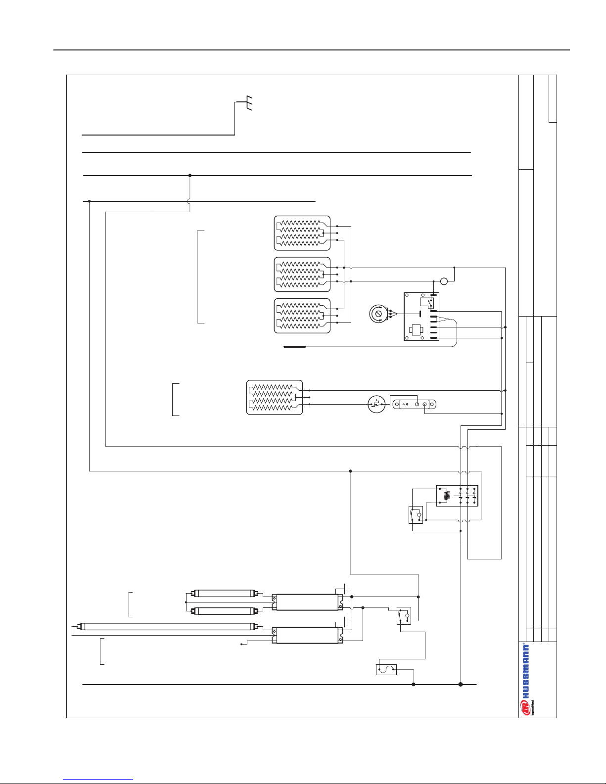
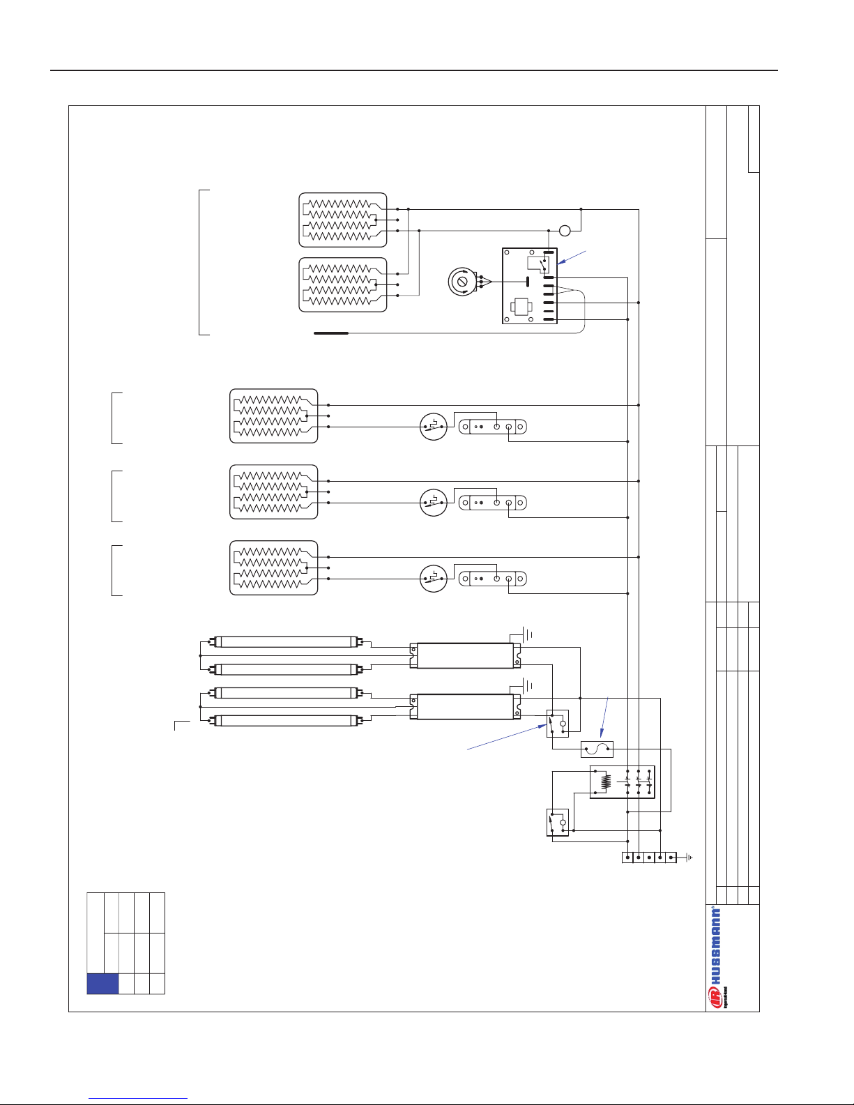
HEDN-05 COMBO
W6300127
4' CASE HOT / COLD COMBO
L
P
H2
L2
L1
H1
PACKTRONICS
CONTROLLER
225-01-3229
L
TEMP. CONTROL
SENSOR
225-01-3228
64
21
5
P1
3 7
BALLAST 125-01-3266
FULHAM LH3-120-L
OVERHEAD HEATER
HATCO™ GLOW-RAY™
950W 3.96A ~240VAC
125-02-1086
GRIDDLE HEATER PAD
487W 2.03A ~240 VAC
225-01-6798T
L
EVAPORATOR
FANS .18A
(2) 4½" AXIAL
125-01-2012
LIGHTS 48"
(4) FP28T8/830
125-03-1133
INFINITE
CONTROL
125-01-1663
OPTIONAL SUCTION
SOLENOID SETUPFOR
COLD SECTION ONLY
LIGHT SWITCH
125-01-0311
BALLAST 125-01-3266
FULHAM LH3-120-L
~ 120 VAC - 50/60 Hz.
L1 N
BUNDLE COLOR
BLACK / WHITE
T-STAT
SUCTION
SOLENOID
VALVE
M
M
L
MAIN POWER
~208 / ~240 VAC - 50/60 HZ
PILOT LIGHT
175-01-1102C
PILOT LIGHT
175-01-1102C
TERMINAL
BLOCK
125-01-0295
L1
L2NG
225-01-6954
8.6x45.7
642 WATTS
2.68 AMPS @ 240 VAC
THERMOSTAT
TEMPCO
TEB33000
225-01-1700
LIMIT SWITCH
TEMPCO TST-112-119
225-01-1702
SHELF
CONTACTOR
SQUARE -D
8910DPA43V02
125-01-1001
LIGHT CIRCUIT= .93A
BLK # 14
WHT # 14
RED # 14
BLK # 14
BLK # 14
WHITE # 14
RED # 14
BLK # 14
BLK # 14
WHITE # 14
NOTE:
CASE MUST
BE GROUNDED
10.0
8.7
8.8
7.5
L1
L2
L3
208 V 240 V
LOADING
964655
Wiring Diagrams (Cont'd)
31
Page 32

DATE:
PROJECT TITLE:
DRAWING #:
DRAWN BY:
PRODUCTION ORDER #:
DRAWING TITLE:
DATE:
Hussmann Corporation, Int'l.
13770 Ramona Avenue
Chino, CA. 91710
(909)-590-4910 Lic.#: 644406
REVISIONS:
#: DESCRIPTION:
CHECKED BY:
BY:
FILE LOCATION:
ECD
XXX
PAGE OF1
1
01/17/07
123
Eng:\WIRESCHEMATICS\NEW -WIRING
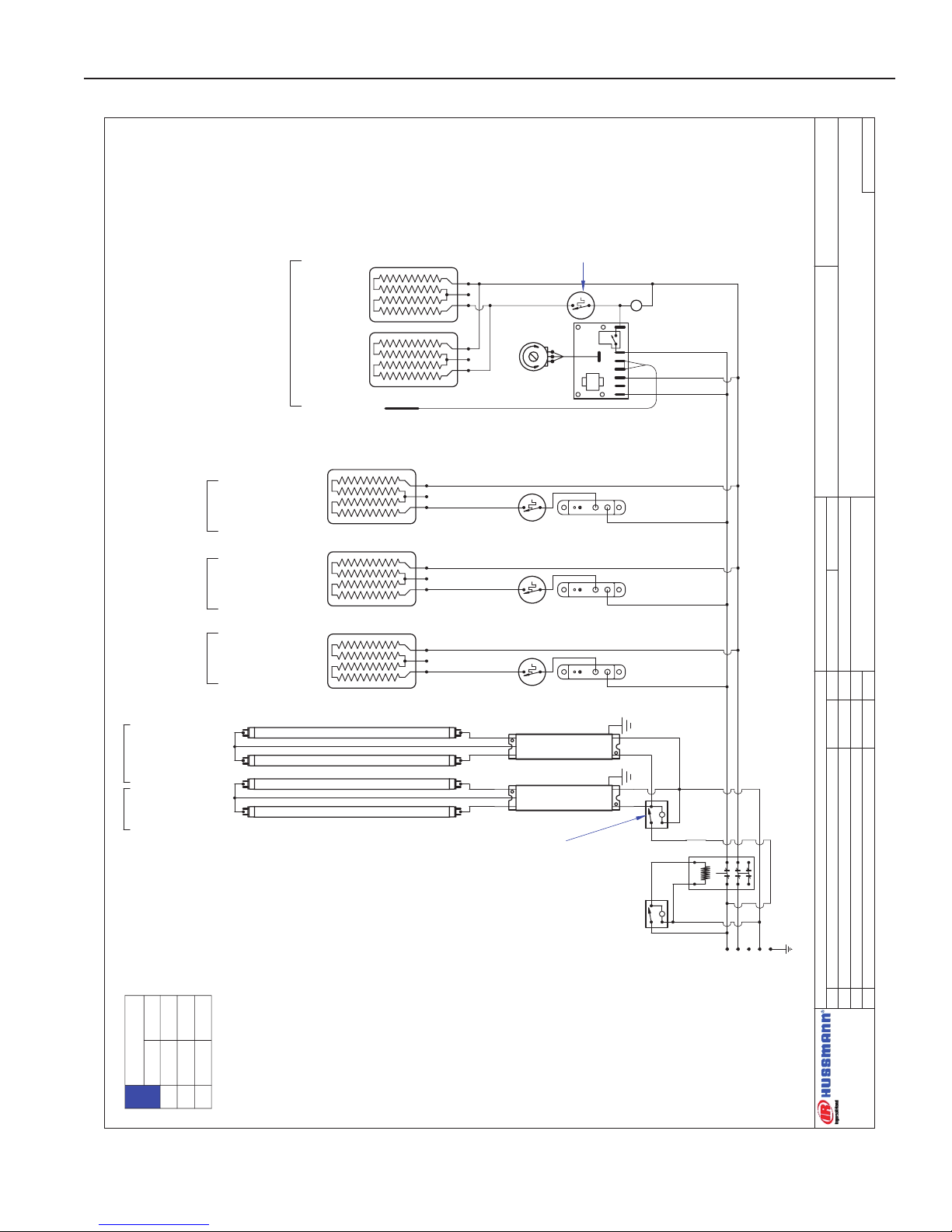
HEDN-05
W6300106
5' CASE WIRING DIAGRAM
225-01-6961
13.6x57.7
1177 WATTS
4.90 AMPS @ 240 VAC
THERMOSTAT
TEMPCO
TEB33000
225-01-1700
LIMIT SWITCH
TEMPCO TST-112-119
225-01-1702
225-01-6960
12.6x57.7
1090 WATTS
4.54 AMPS @ 240 VAC
THERMOSTAT
TEMPCO
TEB33000
225-01-1700
LIMIT SWITCH
TEMPCO TST-112-119
225-01-1702
225-01-6959
10.6x57.7
917 WATTS
3.82 AMPS @ 240 VAC
THERMOSTAT
TEMPCO
TEB33000
225-01-1700
LIMIT SWITCH
TEMPCO TST-112-119
225-01-1702
225-01-6958
8.6x57.7
744 WATTS
3.10 AMPS @ 240 VAC
THERMOSTAT
TEMPCO
TEB33000
225-01-1700
LIMIT SWITCH
TEMPCO TST-112-119
225-01-1702
SHELF- #1 -9.5"-TOP
SHELF- #2 -11.5"
SHELF- #3 -13.5"
SHELF- #4 -14.5"
GRIDDLE-#5-Bottom
225-01-6787T
19.0x18.0
342 WATTS
1.43 AMPS @ 240 VAC
225-01-6786T
11.0x18.0
198 WATTS
0.83 AMPS @ 240 VAC
225-01-6787T
19.0x18.0
342 WATTS
1.43 AMPS @ 240 VAC
PACKTRONICS
CONTROLLER
225-01-3229
PILOT LIGHT
175-01-1102C
L
TEMP. CONTROL
SENSOR
225-01-3228
6421 5
P1
3 7
SWITCH
125-01-0311
L
LIGHT SWITCH
TIPPETTE
125-01-0311
15 AMP FUSE
125-01-3282
FUSE HOLDER
125-01-3283
~208 / 240 VAC -3Ø - 50/60 Hz. - 5W
L1
L2
L3NG
CONTACTOR
SQUARE -D
8910DPA43V02
125-01-1001
MAIN
POWER
L
SHELF LIGHTING
(2) FP14T5/830 2'
125-03-1127
SHELVES
BALLAST 125-01-3267
FULHAM LH4-120-L
CANOPY
OVERHEAD LIGHTING
(1) FP35T5/830 5'
125-03-1136
CAP UNUSED RED LEAD
BALLAST 125-01-3267
FULHAM LH4-120-L
BALLAST 125-01-3267
FULHAM LH4-120-L
SHELF LIGHTING
(2) FP14T5/830 2'
125-03-1127
BALLAST 125-01-3267
FULHAM LH4-120-L
SHELF LIGHTING
(2) FP14T5/830 2'
125-03-1127
BALLAST 125-01-3267
FULHAM LH4-120-L
SHELF LIGHTING
(2) FP14T5/830 2'
125-03-1127
LOADING
208 V 240 V
L1
L2
L3
18.6
17.4
~
21.3
20.1
~
NOTE:
CASE MUST
BE GROUNDED
Wiring Diagrams (Cont'd)
IGHT-HEDN, HEDN COMBO, HEDW-0508
32
Page 33

Rev. 0508
DATE:
PROJECT TITLE:
DRAWING #:
DRAWN BY:
PRODUCTION ORDER #:
DRAWING TITLE:
DATE:
Hussmann Corporation, Int'l.
13770 Ramona Avenue
Chino, CA. 91710
(909)-590-4910 Lic.#: 644406
REVISIONS:
#: DESCRIPTION:
CHECKED BY:
BY:
FILE LOCATION:
D.QUAN
---
PAGE OF1
2
05/18/06
A re-calculated for 1.5W shelf heater pads 02/12/07 ECD
B Updated dwg; revised load ratings; added sheet 2 5/16/07 JR
HEDN-05
W6300081
6' CASE - WIRING DIAGRAM
PACKTRONICS
CONTROLLER
225-01-3229
PILOT LIGHT
175-01-1102C
L
TEMP. CONTROL
6421 5
P1
3 7
BALLAST 125-01-3267
FULHAM LH4-120-L
BALLAST 125-01-3267
FULHAM LH4-120-L
BALLAST 125-01-3267
FULHAM LH4-120-L
SENSOR
225-01-3228
LIGHT SWITCH
TIPPETTE
125-01-0311
L
SWITCH
125-01-0311
~208 / ~240 VAC - 50/60 HZ
L
CONTACTOR
SQUARE -D
8910DPA43V02
125-01-1001
BALLAST 125-01-3267
FULHAM LH4-120-L
BALLAST 125-01-3267
FULHAM LH4-120-L
225-01-6962
8.6x69.7
979 WATTS
4.08 AMPS @ 240 VAC
225-01-6963
10.6x69.7
1207 WATTS
5.03 AMPS @ 240 VAC
225-01-6964
12.6x69.7
1434 WATTS
5.98 AMPS @ 240 VAC
225-01-6965
13.6x69.7
1548 WATTS
6.45 AMPS @ 240 VAC
THERMOSTAT
TEMPCO
TEB33000
225-01-1700
LIMIT SWITCH
TEMPCO TST-112-119
225-01-1702
THERMOSTAT
TEMPCO
TEB33000
225-01-1700
LIMIT SWITCH
TEMPCO TST-112-119
225-01-1702
THERMOSTAT
TEMPCO
TEB33000
225-01-1700
LIMIT SWITCH
TEMPCO TST-112-119
225-01-1702
THERMOSTAT
TEMPCO
TEB33000
225-01-1700
LIMIT SWITCH
TEMPCO TST-112-119
225-01-1702
15 AMP FUSE
125-01-8604
FUSE HOLDER
125-01-8605
SHELF- #1
9.5"-TOP
SHELF- #2
11.5"
SHELF- #3
13.5"
SHELF- #4
14.5"
225-01-6787T
342 WATTS
1.43 AMPS @ 240VAC
225-01-6787T
342 WATTS
1.43 AMPS @ 240VAC
225-01-6787T
342 WATTS
1.43 AMPS @ 240VAC
GRIDDLE-#5-Bottom
OVERHEAD LIGHTING
(2) FP21T5/830 3'
125-03-1130
SHELF LIGHTING
(2) FP21T5/830 3'
125-03-1130
SHELVES
CANOPY
SHELF LIGHTING
(2) FP21T5/830 3'
125-03-1130
SHELF LIGHTING
(2) FP21T5/830 3'
125-03-1130
SHELF LIGHTING
(2) FP21T5/830 3'
125-03-1130
L1
L2
L3
N
G
(3) 20 AMP FUSE 125-01-8537
FUSE HOLDER 125-01-8545
(2) 20 AMP FUSE
125-01-8537
FUSE HOLDER
(2) 125-01-3285
BLK # 12
RED # 14
WHITE # 14
GRN # 12
LIGHT CIRCUIT= 1.75A
BLUE # 12
BLK # 14
RED # 12
BLK # 14
BLUE # 14
BLK # 14
BLUE # 14
LOADING
208 V 240 V
L1
L2
L3
14.6
18.7
13.3
16.6
21.5
15.3
NOTE:
CASE MUST
BE GROUNDED
Wiring Diagrams (Cont'd)
33
Page 34

IGHT-HEDN, HEDN COMBO, HEDW-0508
DATE:
PROJECT TITLE:
DRAWING #:
DRAWN BY:
PRODUCTION ORDER #:
DRAWING TITLE:
DATE:
Hussmann Corporation, Int'l.
13770 Ramona Avenue
Chino, CA. 91710
(909)-590-4910 Lic.#: 644406
REVISIONS:
#: DESCRIPTION:
CHECKED BY:
BY:
FILE LOCATION:
D.QUAN
---
PAGE OF2
2
05/18/06
A re-calculated for 1.5W shelf heater pads 02/12/07 ECD
B Updated dwg; revised load ratings; added sheet 2 5/16/07 JR
HEDN-05
W6300081
6' CASE - WIRING DIAGRAM
L1
BLACK (BLK)
# 12
WHITE (W)
#14
N
L2
GREEN (G)
# 12
G
BK
RED (R)
# 12
L3
L
SWITCH
125-01-0311
BLUE
(BL) # 12
BLACK
WHITE
L
WHITE
RED
RED
BLUE
BLUE
15 AMP FUSE
125-01-8604
FUSE HOLDER
125-01-8605
(2) 20 AMP FUSE 125-01-8537
(2) FUSE HOLDER 125-01-3285
(3) 20 AMP FUSE 125-01-8537
FUSE HOLDER 125-01-8545
PACKTRONICS
CONTROLLER
225-01-3229
PILOT LIGHT
175-01-1102C
L
TEMP. CONTROL
6421
5
P1
3 7
SENSOR
225-01-3228
225-01-6962
8.6x69.7
979 WATTS
4.08 AMPS @ 240 VAC
225-01-6963
10.6x69.7
1207 WATTS
5.03 AMPS @ 240 VAC
225-01-6964
12.6x69.7
1434 WATTS
5.98 AMPS @ 240 VAC
225-01-6965
13.6x69.7
1548 WATTS
6.45 AMPS @ 240 VAC
THERMOSTAT
TEMPCO
TEB33000
225-01-1700
LIMIT SWITCH
TEMPCO TST-112-119
225-01-1702
THERMOSTAT
TEMPCO
TEB33000
225-01-1700
LIMIT SWITCH
TEMPCO TST-112-119
225-01-1702
THERMOSTAT
TEMPCO
TEB33000
225-01-1700
LIMIT SWITCH
TEMPCO TST-112-119
225-01-1702
THERMOSTAT
TEMPCO
TEB33000
225-01-1700
LIMIT SWITCH
TEMPCO TST-112-119
225-01-1702
SHELF- #1
9.5"-TOP
SHELF- #2
11.5"
SHELF- #3
13.5"
SHELF- #4
14.5"
225-01-6787T
342 WATTS
1.43 AMPS @ 240VAC
225-01-6787T
342 WATTS
1.43 AMPS @ 240VAC
225-01-6787T
342 WATTS
1.43 AMPS @ 240VAC
GRIDDLE-#5-Bottom
BALLAST 125-01-3267
FULHAM LH4-120-L
BALLAST 125-01-3267
FULHAM LH4-120-L
BALLAST 125-01-3267
FULHAM LH4-120-L
BALLAST 125-01-3267
FULHAM LH4-120-L
BALLAST 125-01-3267
FULHAM LH4-120-L
OVERHEAD LIGHTING
(2) FP21T5/830 3'
125-03-1130
SHELF LIGHTING
(2) FP21T5/830 3'
125-03-1130
SHELVES
CANOPY
SHELF LIGHTING
(2) FP21T5/830 3'
125-03-1130
SHELF LIGHTING
(2) FP21T5/830 3'
125-03-1130
SHELF LIGHTING
(2) FP21T5/830 3'
125-03-1130
LIGHT CIRCUIT= 1.75A
Wiring Diagrams (Cont'd)
34
Page 35

Rev. 0508
DATE:
PROJECT TITLE:
DRAWING #:
DRAWN BY:
PRODUCTION ORDER #:
DRAWING TITLE:
DATE:
Hussmann Corporation, Int'l.
13770 Ramona Avenue
Chino, CA. 91710
(909)-590-4910 Lic.#: 644406
REVISIONS:
#: DESCRIPTION:
CHECKED BY:
BY:
FILE LOCATION:
JESSE RIOS
---
PAGE OF1
1
03/15/07
B Made corrections to griddle components 2/11/08 JR
C Griddle circuit corrections: connections missing 2/11/08 JR
D Revise Load Ratings per UL input test 2/12/08 JR
HEDN-05 W/O TOP SHELF
W6300126
6' CASE - WIRING DIAGRAM
PACKTRONICS
CONTROLLER
225-01-3229
PILOT LIGHT
175-01-1102C
L
TEMP. CONTROL
642
1
5
P1
3 7
BALLAST 125-01-3267
FULHAM LH4-120-L
BALLAST 125-01-3267
FULHAM LH4-120-L
BALLAST 125-01-3267
FULHAM LH4-120-L
SENSOR
225-01-3228
LIGHT SWITCH
TIPPETTE
125-01-0311
L
SWITCH
125-01-0311
~208 / ~240 VAC - 50/60 HZ
MAIN
POWER
L
CONTACTOR
SQUARE -D
8910DPA43V02
125-01-1001
BALLAST 125-01-3267
FULHAM LH4-120-L
225-01-6963
10.6x69.7
1207 WATTS 5.03A
@ 240 VAC
225-01-6964
12.6x69.7
1434 WATTS 5.98A
@ 240 VAC
225-01-6965
13.6x69.7
1548 WATTS 6.45A
@ 240 VAC
THERMOSTAT
TEMPCO
TEB33000
225-01-1700
LIMIT SWITCH
TEMPCO TST-112-119
225-01-1702
THERMOSTAT
TEMPCO
TEB33000
225-01-1700
LIMIT SWITCH
TEMPCO TST-112-119
225-01-1702
THERMOSTAT
TEMPCO
TEB33000
225-01-1700
LIMIT SWITCH
TEMPCO TST-112-119
225-01-1702
SHELF- #1
11.5"
SHELF- #2
13.5"
SHELF- #3
14.5"
225-01-6787
342 WATTS 1.43A
@ 240VAC
225-01-6786
198 WATTS 0.83A
@ 240VAC
GRIDDLE--Bottom
OVERHEAD LIGHTING
(2) FP21T5/830 3'
125-03-1130
SHELVES
CANOPY
SHELF LIGHTING
(2) FP21T5/830 3'
125-03-1130
SHELF LIGHTING
(2) FP21T5/830 3'
125-03-1130
SHELF LIGHTING
(2) FP21T5/830 3'
125-03-1130
L1
L2
L3NG
LIGHT CIRCUIT= 1.56A 168W
LIMIT SWITCH
TEMPCO TST-112-119
225-01-1702
BLK # 12
RED # 12
WHT # 14
GRN # 12
BLK # 14
BLUE # 12
225-01-6787
342 WATTS 1.43A
@ 240VAC
20A
20A
20A
15A
15A
(3) 20 AMP FUSE
125-01-8537
FUSE HOLDER
125-01-8545
(2) 15 AMP FUSE
125-01-8604
FUSE HOLDER
125-01-8610
15A
15 AMP FUSE
125-01-8604
FUSE HOLDER
125-01-8605
225-01-6786
198 WATTS 0.83A
@ 240VAC
BLK # 14
BLUE # 14
LOADING
208 V 240 V
L1
L2
L3
9.7
12.6
12.1
10.9
14.6
13.9
NOTE:
CASE MUST
BE GROUNDED
5458W @ 240VAC
4132W @ 208VAC
Wiring Diagrams (Cont'd)
35
Page 36

IGHT-HEDN, HEDN COMBO, HEDW-0508
DATE:
PROJECT TITLE:
DRAWING #:
DRAWN BY:
PRODUCTION ORDER #:
DRAWING TITLE:
DATE:
Hussmann Corporation, Int'l.
13770 Ramona Avenue
Chino, CA. 91710
(909)-590-4910 Lic.#: 644406
REVISIONS:
#: DESCRIPTION:
CHECKED BY:
BY:
FILE LOCATION:
JESSE RIOS
---
PAGE OF1
1
5/2/07
HEDN-05
W6300107
8' CASE WIRING DIAGRAM
L
LIGHT SWITCH
TIPPETTE
125-01-0311
CONTACTOR
SQUARE -D
8910DPA43V02
125-01-1001
L
MAIN
POWER
~208 / ~240 VAC - 50/60 HZ
SWITCH
TIPPETTE
125-01-0311
15 AMP FUSE
125-01-8604
FUSE HOLDER
125-01-8605
225-01-6954
8.6x45.7
642 WATTS
2.68 AMPS @ 240 VAC
225-01-6955
10.6x45.7
791 WATTS
3.30 AMPS @ 240 VAC
THERMOSTAT
TEMPCO
TEB33000
225-01-1700
LIMIT SWITCH
TEMPCO TST-112-119
225-01-1702
225-01-6956
12.6x45.7
940 WATTS
3.92 AMPS @ 240 VAC
THERMOSTAT
TEMPCO
TEB33000
225-01-1700
LIMIT SWITCH
TEMPCO TST-112-119
225-01-1702
225-01-6957
13.6x45.7
1015 WATTS
4.23 AMPS @ 240 VAC
THERMOSTAT
TEMPCO
TEB33000
225-01-1700
LIMIT SWITCH
TEMPCO TST-112-119
225-01-1702
BALLAST 125-01-3267
FULHAM LH4-120-L
BALLAST 125-01-3267
FULHAM LH4-120-L
BALLAST 125-01-3267
FULHAM LH4-120-L
BALLAST 125-01-3267
FULHAM LH4-120-L
BALLAST 125-01-3267
FULHAM LH4-120-L
OVERHEAD LIGHTING
(2) FP28T5/830 4'
125-03-1133
SHELF LIGHTING
(2) FP28T5/830 4'
125-03-1133
SHELVES
CANOPY
SHELF LIGHTING
(2) FP28T5/830 4'
125-03-1133
SHELF LIGHTING
(2) FP28T5/830 4'
125-03-1133
SHELF LIGHTING
(2) FP28T5/830 4'
125-03-1133
PACKTRONICS
CONTROLLER
225-01-3229
L
TEMP. CONTROL
SENSOR
225-01-3228
64
2
1
5
P1
3 7
PILOT LIGHT
175-01-1102C
225-01-6787T
342 WATTS
1.43 AMPS @ 240VAC
225-01-6787T
342 WATTS
1.43 AMPS @ 240VAC
GRIDDLE-RIGHT-BOTTOM
SHELF-9.5"-RIGHT-TOP
SHELF-11.5"-RIGHT
SHELF-13.5"-RIGHT
SHELF-14.5"-RIGHT
225-01-6954
8.6x45.7
642 WATTS
2.68 AMPS @ 240 VAC
THERMOSTAT
TEMPCO
TEB33000
225-01-1700
LIMIT SWITCH
TEMPCO TST-112-119
225-01-1702
225-01-6955
10.6x45.7
791 WATTS
3.30 AMPS @ 240 VAC
THERMOSTAT
TEMPCO
TEB33000
225-01-1700
LIMIT SWITCH
TEMPCO TST-112-119
225-01-1702
225-01-6956
12.6x45.7
940 WATTS
3.92 AMPS @ 240 VAC
THERMOSTAT
TEMPCO
TEB33000
225-01-1700
LIMIT SWITCH
TEMPCO TST-112-119
225-01-1702
225-01-6957
13.6x45.7
1015 WATTS
4.23 AMPS @ 240 VAC
THERMOSTAT
TEMPCO
TEB33000
225-01-1700
LIMIT SWITCH
TEMPCO TST-112-119
225-01-1702
PACKTRONICS
CONTROLLER
225-01-3229
L
TEMP. CONTROL
SENSOR
225-01-3228
6
42
1
5
P1
3 7
PILOT LIGHT
175-01-1102C
225-01-6787T
342 WATTS
1.43 AMPS @ 240VAC
225-01-6787T
342 WATTS
1.43 AMPS @ 240VAC
GRIDDLE-LEFT-BOTTOM
SHELF-9.5"-LEFT-TOP
SHELF-11.5"-LEFT
SHELF-13.5"-LEFT
SHELF-14.5"-LEFT
L1
L2
L3
N
G
BLK # 10
RED # 10
W # 14
BLUE # 10
GRN # 10
BLK # 10
RED # 10
BLUE # 10
BLK # 10
RED # 10
BLUE # 10
RED # 10
BLUE # 10
THERMOSTAT
TEMPCO
TEB33000
225-01-1700
LIMIT SWITCH
TEMPCO TST-112-119
225-01-1702
LIGHT CIRCUIT= 2.33A
(3) 15 AMP FUSE
125-01-8604
(3)FUSE HOLDER
125-01-8605
(3) 15 AMP FUSE
125-01-8604
(3)FUSE HOLDER
125-01-8605
LOADING
208 V 240 V
L1L2L3
21.1
22.7
17.5
24.0
26.1
20.2
NOTE:
CASE MUST
BE GROUNDED
Wiring Diagrams (Cont'd)
36
Page 37

Rev. 0508
DATE:
PROJECT TITLE:
DWG #:DRAWN BY:
PRODUCTION ORDER #:
DRAWING TITLE:
DATE:
REVISIONS:
:YB DEKCE
H
C:NOITPIRCSED :#
BY:
FILE LOCATION:
Mark Cipriani
PAGE OF
HUSSMANN® CORPORATION
13770 RAMONA AVENUE
CHINO, CA.91710
(909) 590-4910 LIC.#: 644406
1 2
01/09/07
HEDW-02 CASES
W6300108
3' CASE WIRING DIAGRAM
A Updated drawing, removed ballast fuse; A dded Sheet # 2 5/9/07 JR
BALLAST 125-01-3267
FULHAM LH4-120-L
CANOPY SHELF
~208 / 240 VAC - 50/60 Hz.
CONTACTOR
SQUARE -D
8910DPA43V02
125-01-1001
L
SWITCH
125-01-0311
L
LIGHT SWITCH
TIPPETTE
125-01-0311
225-01-6951
10.6x33.7
583 WATTS
2.43 AMPS @ 240 VAC
THERMOSTAT
TEMPCO
TEB33000
225-01-1700
LIMIT SWITCH
TEMPCO TST-112-119
225-01-1702
225-01-6950
8.6x33.7
473 WATTS
1.97 AMPS @ 240 VAC
THERMOSTAT
TEMPCO
TEB33000
225-01-1700
LIMIT SWITCH
TEMPCO TST-112-119
225-01-1702
CASE LIGHTS
(2) FP21T5/830 3'
125-03-1130
PACKTRONICS
CONTROLLER
225-01-3229
PILOT LIGHT
175-01-1102C
L
TEMP. CONTROL
6421 5
P1
3 7
SENSOR
225-01-3228
225-01-6776T
21.5x26.5
553W
2.30 AMPS @ ~240VAC
GRIDDLE-#2-Bottom
225-01-6775T
11.5x26.5
292W
1.22 AMPS @ ~240VAC
SHELF- #1 -20.5"-Top
L1
L2
N
G
BLK # 14
RED # 14
WHITE # 14
GRN # 14
LIGHT CIRCUIT= .35A
BLK # 14
BLK # 14
RED # 14
NOTE:
CASE MUST
BE GROUNDED
8.3
7.9
7.2
6.9
L1
L2
L3
208 V 240 V
LOADING
Wiring Diagrams (Cont'd)
37
Page 38

DATE:
PROJECT TITLE:
DWG #:DRAWN BY:
PRODUCTION ORDER #:
DRAWING TITLE:
DATE:
REVISIONS:
:YB DEKCE
H
C:NOITPIRCSED :#
BY:
FILE LOCATION:
Mark Cipriani
PAGE OF
HUSSMANN® CORPORATION
13770 RAMONA AVENUE
CHINO, CA.91710
(909) 590-4910 LIC.#: 644406
2 2
01/09/07
HEDW-02 CASES
W6300108
3' CASE WIRING DIAGRAM
A Updated drawing, removed ballast fuse; A dded Sheet # 2 5/9/07 JR
L1
BLACK (BLK)
# 14
WHITE (W)
#14
N
L2
GREEN (G)
# 14
G
BK
RED (R)
# 14
L3
L
SWITCH
125-01-0311
BLACK
WHITE
L
WHITE
RED
RED
BALLAST 125-01-3267
FULHAM LH4-120-L
CANOPY SHELF
CASE LIGHTS
(2) FP21T5/830 3'
125-03-1130
LIGHT CIRCUIT= .35A
225-01-6951
10.6x33.7
583 WATTS
2.43 AMPS @ 240 VAC
THERMOSTAT
TEMPCO
TEB33000
225-01-1700
LIMIT SWITCH
TEMPCO TST-112-119
225-01-1702
225-01-6950
8.6x33.7
473 WATTS
1.97 AMPS @ 240 VAC
THERMOSTAT
TEMPCO
TEB33000
225-01-1700
LIMIT SWITCH
TEMPCO TST-112-119
225-01-1702
PACKTRONICS
CONTROLLER
225-01-3229
PILOT LIGHT
175-01-1102C
L
TEMP. CONTROL
642
1
5
P1
3 7
SENSOR
225-01-3228
225-01-6776T
21.5x26.5
553W
2.30 AMPS @ ~240VAC
GRIDDLE-#2-Bottom
225-01-6775T
11.5x26.5
292W
1.22 AMPS @ ~240VAC
SHELF- #1 -20.5"-Top
Wiring Diagrams (Cont'd)
IGHT-HEDN, HEDN COMBO, HEDW-0508
38
Page 39

Rev. 0508
DATE:
PROJECT TITLE:
DRAWING #:
DRAWN BY:
PRODUCTION ORDER #:
DRAWING TITLE:
DATE:
Hussmann Corporation, Int'l.
13770 Ramona Avenue
Chino, CA. 91710
(909)-590-4910 Lic.#: 644406
REVISIONS:
#: DESCRIPTION:
CHECKED BY:
BY:
FILE LOCATION:
ECD
PAGE OF1
1
12/21/06
B Updated dwg; added 225-01-1702 2/8/08 JR
HEDW-02
W6300109
4' CASE WIRING DIAGRAM
BALLAST 125-01-3267
FULHAM LH4-120-L
L
LIGHT SWITCH
TIPPETTE
125-01-0311
L
MAIN
POWER
~208 / ~240 VAC 50/60 HZ
125-01-1001
SQUARE -D
CONTACTOR
8910DPA43V02
SWITCH
125-01-0311
(2) 553W 2.3A
@ ~240VAC
225-01-6776T
225-01-6955
10.6x45.7
791 WATTS
3.30 AMPS @ 240 VAC
THERMOSTAT
TEMPCO
TEB33000
225-01-1700
LIMIT SWITCH
TEMPCO TST-112-119
225-01-1702
225-01-6954
8.6x45.7
642 WATTS
2.68 AMPS @ 240 VAC
THERMOSTAT
TEMPCO
TEB33000
225-01-1700
LIMIT SWITCH
TEMPCO TST-112-119
225-01-1702
GRIDDLE-#2-Bottom
SHELF- #1 -20.5"-TOP
PACKTRONICS
CONTROLLER
225-01-3229
PILOT LIGHT
175-01-1102C
L
TEMP. CONTROL
SENSOR
225-01-3228
6421 5
P1
3 7
SHELF
CANOPY
OVERHEAD LIGHTING
(1) FP28T5/830 4'
125-03-1133
SHELF LIGHTING
(1) FP28T5/830 4'
125-03-1133
L1
L2
N
G
LIMIT SWITCH
TEMPCO TST-112-119
225-01-1702
LIGHT CIRCUIT= .52A 56W
K.M.
LOADING
208 V 240 V
L1
L2
9.7
9.2
11.1
10.6
NOTE:
CASE MUST
BE GROUNDED
Wiring Diagrams (Cont'd)
39
Page 40

DATE:
PROJECT TITLE:
DRAWING #:
DRAWN BY:
PRODUCTION ORDER #:
DRAWING TITLE:
DATE:
Hussmann Corporation, Int'l.
13770 Ramona Avenue
Chino, CA. 91710
(909)-590-4910 Lic.#: 644406
REVISIONS:
#: DESCRIPTION:
CHECKED BY:
BY:
FILE LOCATION:
PAGE OF1
2
5/9/07
HEDW-02
W6300110
5' CASE WIRING DIAGRAM
L
L
~208 / ~240 VAC - 50/60 HZ
SWITCH
125-01-0311
225-01-6959
10.6x57.7
1000 WATTS
4.17 AMPS @ 240 VAC
THERMOSTAT
TEMPCO
TEB33000
225-01-1700
LIMIT SWITCH
TEMPCO TST-112-119
225-01-1702
225-01-6958
8.6x57.7
810 WATTS
3.38 AMPS @ 240 VAC
THERMOSTAT
TEMPCO
TEB33000
225-01-1700
LIMIT SWITCH
TEMPCO TST-112-119
225-01-1702
SHELF- #1 -18.5"-TOP
GRIDDLE-#2-Bottom
225-01-6776T
21.5x26.5
553 WATTS
2.30 AMPS @ 240 VAC
225-01-6775T
11.5x26.5
292 WATTS
1.22 AMPS @ 240 VAC
225-01-6776T
21.5x26.5
553 WATTS
2.30 AMPS @ 240 VAC
LIGHT SWITCH
TIPPETTE
125-01-0311
CONTACTOR
SQUARE -D
8910DPA43V02
125-01-1001
PACKTRONICS
CONTROLLER
225-01-3229
PILOT LIGHT
125-01-1102C
L
TEMP. CONTROL
SENSOR
225-01-3228
6421 5
P1
3 7
BALLAST 125-01-3267
FULHAM LH4-120-L
BALLAST 125-01-3267
FULHAM LH4-120-L
OVERHEAD LIGHTING
(1) FP35T5/830 5'
125-03-1136
SHELF
CANOPY
SHELF LIGHTING
(2) FP14T5/830 2'
125-03-1127
CAP UNUSED RED LEAD
BLK # 14
RED # 14
WHITE # 14
GRN # 14
BLK # 14
L1L2L3
N
G
LIGHT CIRCUIT= .53A
BLK # 14
RED # 14
JESSE RIOS
LOADING
208 V 240 V
L1
L2
L3
12.1
11.6
13.9
13.4
NOTE:
CASE MUST
BE GROUNDED
A Updated, removed ballast fuse; Added Sheet # 2 5/9/07 JR
Wiring Diagrams (Cont'd)
IGHT-HEDN, HEDN COMBO, HEDW-0508
40
Page 41

Rev. 0508
DATE:
PROJECT TITLE:
DRAWING #:
DRAWN BY:
PRODUCTION ORDER #:
DRAWING TITLE:
DATE:
Hussmann Corporation, Int'l.
13770 Ramona Avenue
Chino, CA. 91710
(909)-590-4910 Lic.#: 644406
REVISIONS:
#: DESCRIPTION:
CHECKED BY:
BY:
FILE LOCATION:
PAGE OF2
2
5/9/07
HEDW-02
W6300110
5' CASE WIRING DIAGRAM
JESSE RIOS
L1
BLACK (BLK)
# 14
WHITE (W)
#14
N
L2
GREEN (G)
# 14
G
BK
RED (R)
# 14
L3
L
SWITCH
125-01-0311
BLACK
WHITE
L
WHITE
RED
RED
BALLAST 125-01-3267
FULHAM LH4-120-L
BALLAST 125-01-3267
FULHAM LH4-120-L
225-01-6959
10.6x57.7
1000 WATTS
4.17 AMPS @ 240 VAC
THERMOSTAT
TEMPCO
TEB33000
225-01-1700
LIMIT SWITCH
TEMPCO TST-112-119
225-01-1702
225-01-6958
8.6x57.7
810 WATTS
3.38 AMPS @ 240 VAC
THERMOSTAT
TEMPCO
TEB33000
225-01-1700
LIMIT SWITCH
TEMPCO TST-112-119
225-01-1702
SHELF- #1 -18.5"-TOP
GRIDDLE-#2-Bottom
225-01-6776T
21.5x26.5
553 WATTS
2.30 AMPS @ 240 VAC
225-01-6775T
11.5x26.5
292 WATTS
1.22 AMPS @ 240 VAC
225-01-6776T
21.5x26.5
553 WATTS
2.30 AMPS @ 240 VAC
PACKTRONICS
CONTROLLER
225-01-3229
PILOT LIGHT
125-01-1102C
L
TEMP. CONTROL
SENSOR
225-01-3228
64
2
1 5
P1
3 7
LIGHT CIRCUIT= .53A
SHELF
CANOPY
CAP UNUSED RED LEAD
OVERHEAD LIGHTING
(1) FP35T5/830 5'
125-03-1136
SHELF LIGHTING
(2) FP14T5/830 2'
125-03-1127
A Updated, removed ballast fuse; Added Sheet # 2 5/9/07 JR
Wiring Diagrams (Cont'd)
41
Page 42

IGHT-HEDN, HEDN COMBO, HEDW-0508
DATE:
PROJECT TITLE:
DRAWING #:
DRAWN BY:
PRODUCTION ORDER #:
DRAWING TITLE:
DATE:
Hussmann Corporation, Int'l.
13770 Ramona Avenue
Chino, CA. 91710
(909)-590-4910 Lic.#: 644406
REVISIONS:
#: DESCRIPTION:
CHECKED BY:
BY:
FILE LOCATION:
JESSE RIOS
---
PAGE OF1
2
5/9/07
HEDW-02
W6300111
6' CASE WIRING DIAGRAM
LIGHT SWITCH
TIPPETTE
125-01-0311
L
SWITCH
125-01-0311
~208 / ~240 VAC - 50/60 HZ
L
CONTACTOR
SQUARE -D
8910DPA43V02
125-01-1001
OVERHEAD LIGHTING
(2) FP21T5/830 3'
125-03-1130
PACKTRONICS
CONTROLLER
225-01-3229
L
TEMP. CONTROL
SENSOR
225-01-3228
6421 5
P1
3 7
SHELF LIGHTING
(2) FP21T5/830 3'
125-03-1130
THERMOSTAT
TEMPCO
TEB33000
225-01-1700
LIMIT SWITCH
TEMPCO TST-112-119
225-01-1702
THERMOSTAT
TEMPCO
TEB33000
225-01-1700
LIMIT SWITCH
TEMPCO TST-112-119
225-01-1702
225-01-6963
10.6x69.7
1108 WATTS
4.62 AMPS @ 240 VAC
225-01-6962
8.6x69.7
899 WATTS
3.75 AMPS @ 240 VAC
225-01-6776T
21.5x26.5
553W
2.30 AMPS @ ~240VAC
225-01-6776T
21.5x26.5
553W
2.30 AMPS @ ~240VAC
GRIDDLE-#2-Bottom
225-01-6776T
21.5x26.5
553W
2.30 AMPS @ ~240VAC
PILOT LIGHT
175-01-1102C
SHELF- #1 -20.5"-TOP
SHELVES
CANOPY
BALLAST 125-01-3267
FULHAM LH4-120-L
BALLAST 125-01-3267
FULHAM LH4-120-L
L1L2L3
N
G
BLK # 14
RED # 14
WHITE # 14
GRN # 14
BLK # 14
LIGHT CIRCUIT= 0.7A
BLUE # 14
RED # 14
BLUE # 14
LOADING
208 V 240 V
L1
L2
L3
8.6
9.5
10.4
9.8
11.0
11.9
NOTE:
CASE MUST
BE GROUNDED
Wiring Diagrams (Cont'd)
42
Page 43

Rev. 0508
DATE:
PROJECT TITLE:
DRAWING #:
DRAWN BY:
PRODUCTION ORDER #:
DRAWING TITLE:
DATE:
Hussmann Corporation, Int'l.
13770 Ramona Avenue
Chino, CA. 91710
(909)-590-4910 Lic.#: 644406
REVISIONS:
#: DESCRIPTION:
CHECKED BY:
BY:
FILE LOCATION:
JESSE RIOS
---
PAGE OF2
2
5/9/07
HEDW-02
W6300111
6' CASE WIRING DIAGRAM
L1
BLACK (BLK)
# 14
WHITE (W)
#14
N
L2
GREEN (G)
# 14
G
BK
RED (R)
# 14
L3
L
SWITCH
125-01-0311
BLUE
(BL) # 14
BLACK
WHITE
L
WHITE
RED
RED
BLUE
BLUE
BALLAST 125-01-3267
FULHAM LH4-120-L
BALLAST 125-01-3267
FULHAM LH4-120-L
OVERHEAD LIGHTING
(2) FP21T5/830 3'
125-03-1130
SHELF LIGHTING
(2) FP21T5/830 3'
125-03-1130
SHELVES
CANOPY
LIGHT CIRCUIT= 0.7A
PACKTRONICS
CONTROLLER
225-01-3229
L
TEMP. CONTROL
SENSOR
225-01-3228
6421 5
P1
3 7
THERMOSTAT
TEMPCO
TEB33000
225-01-1700
LIMIT SWITCH
TEMPCO TST-112-119
225-01-1702
THERMOSTAT
TEMPCO
TEB33000
225-01-1700
LIMIT SWITCH
TEMPCO TST-112-119
225-01-1702
225-01-6963
10.6x69.7
1108 WATTS
4.62 AMPS @ 240 VAC
225-01-6962
8.6x69.7
899 WATTS
3.75 AMPS @ 240 VAC
225-01-6776T
21.5x26.5
553W
2.30 AMPS @ ~240VAC
225-01-6776T
21.5x26.5
553W
2.30 AMPS @ ~240VAC
GRIDDLE-#2-Bottom
225-01-6776T
21.5x26.5
553W
2.30 AMPS @ ~240VAC
PILOT LIGHT
175-01-1102C
SHELF- #1 -20.5"-TOP
Wiring Diagrams (Cont'd)
43
Page 44

DATE:
PROJECT TITLE:
DRAWING #:
DRAWN BY:
PRODUCTION ORDER #:
DRAWING TITLE:
DATE:
Hussmann Corporation, Int'l.
13770 Ramona Avenue
Chino, CA. 91710
(909)-590-4910 Lic.#: 644406
REVISIONS:
#: DESCRIPTION:
CHECKED BY:
BY:
FILE LOCATION:
JESSE RIOS
---
PAGE OF1
2
5/9/07
HEDW-02
W6300112
8' CASE WIRING DIAGRAM
BALLAST 125-01-3267
FULHAM LH4-120-L
L
LIGHT SWITCH
TIPPETTE
125-01-0311
L
~208 / ~240 VAC - 50/60 HZ
125-01-0002
SQUARE -D
CONTACTOR
8910DPA43V02
SWITCH
125-01-0311
BALLAST 125-01-3267
FULHAM LH4-120-L
THERMOSTAT
TEMPCO
TEB33000
225-01-1700
LIMIT SWITCH
TEMPCO TST-112-119
225-01-1702
THERMOSTAT
TEMPCO
TEB33000
225-01-1700
LIMIT SWITCH
TEMPCO TST-112-119
225-01-1702
225-01-6955
10.6x45.7
727 WATTS
3.03 AMPS @ 240 VAC
225-01-6954
8.6x45.7
590 WATTS
2.46 AMPS @ 240 VAC
THERMOSTAT
TEMPCO
TEB33000
225-01-1700
LIMIT SWITCH
TEMPCO TST-112-119
225-01-1702
THERMOSTAT
TEMPCO
TEB33000
225-01-1700
LIMIT SWITCH
TEMPCO TST-112-119
225-01-1702
225-01-6955
10.6x45.7
727 WATTS
3.03 AMPS @ 240 VAC
225-01-6954
8.6x45.7
590 WATTS
2.46 AMPS @ 240 VAC
OVERHEAD LIGHTING
(2) FP28T5/830 4'
125-03-1133
SHELF LIGHTING
(2) FP28T5/830 4'
125-03-1133
SHELVES
CANOPY
SHELF-20.5"-LEFT-TOP
PACKTRONICS
CONTROLLER
225-01-3229
L
TEMP. CONTROL
642
1
5
P1
3 7
SENSOR
225-01-3228
PILOT LIGHT
175-01-1102C
225-01-6776T
21.5x26.5
553W
2.30 AMPS @ ~240VAC
GRIDDLE-LEFT-BOTTOM
225-01-6776T
21.5x26.5
553W
2.30 AMPS @ ~240VAC
PACKTRONICS
CONTROLLER
225-01-3229
L
TEMP. CONTROL
6421 5
P1
3 7
SENSOR
225-01-3228
PILOT LIGHT
175-01-1102C
225-01-6776T
21.5x26.5
553W
2.30 AMPS @ ~240VAC
GRIDDLE-RIGHT-BOTTOM
225-01-6776T
21.5x26.5
553W
2.30 AMPS @ ~240VAC
SHELF-20.5"-RIGHT-TOP
L1L2L3NG
BLK # 14
RED # 14
WHITE # 14
GRN # 14
BLK # 14
LIGHT CIRCUIT= .93A
BLUE # 14
BLK # 14
RED # 14
BLUE # 14
BLK # 14
RED # 14
BLUE # 14
LOADING
208 V 240 V
L1
L2
L3
13.6
10.4
13.7
15.5
12.0
15.8
NOTE:
CASE MUST
BE GROUNDED
Wiring Diagrams (Cont'd)
IGHT-HEDN, HEDN COMBO, HEDW-0508
44
Page 45

Rev. 0508
DATE:
PROJECT TITLE:
DRAWING #:
DRAWN BY:
PRODUCTION ORDER #:
DRAWING TITLE:
DATE:
Hussmann Corporation, Int'l.
13770 Ramona Avenue
Chino, CA. 91710
(909)-590-4910 Lic.#: 644406
REVISIONS:
#: DESCRIPTION:
CHECKED BY:
BY:
FILE LOCATION:
JESSE RIOS
---
PAGE OF2
2
5/9/07
HEDW-02
W6300112
8' CASE WIRING DIAGRAM
L1
BLACK (BLK)
# 14
WHITE (W)
#14
N
L2
GREEN (G)
# 14
G
BK
RED (R)
# 14
L3
L
SWITCH
125-01-0311
BLUE
(BL) # 14
BLACK
WHITE
L
WHITE
RED
RED
BLUE
BLUE
BALLAST 125-01-3267
FULHAM LH4-120-L
BALLAST 125-01-3267
FULHAM LH4-120-L
THERMOSTAT
TEMPCO
TEB33000
225-01-1700
LIMIT SWITCH
TEMPCO TST-112-119
225-01-1702
THERMOSTAT
TEMPCO
TEB33000
225-01-1700
LIMIT SWITCH
TEMPCO TST-112-119
225-01-1702
225-01-6955
10.6x45.7
727 WATTS
3.03 AMPS @ 240 VAC
225-01-6954
8.6x45.7
590 WATTS
2.46 AMPS @ 240 VAC
THERMOSTAT
TEMPCO
TEB33000
225-01-1700
LIMIT SWITCH
TEMPCO TST-112-119
225-01-1702
THERMOSTAT
TEMPCO
TEB33000
225-01-1700
LIMIT SWITCH
TEMPCO TST-112-119
225-01-1702
225-01-6955
10.6x45.7
727 WATTS
3.03 AMPS @ 240 VAC
225-01-6954
8.6x45.7
590 WATTS
2.46 AMPS @ 240 VAC
SHELF-20.5"-LEFT-TOP
PACKTRONICS
CONTROLLER
225-01-3229
L
TEMP. CONTROL
64
21
5
P1
3 7
SENSOR
225-01-3228
PILOT LIGHT
175-01-1102C
225-01-6776T
21.5x26.5
553W
2.30 AMPS @ ~240VAC
GRIDDLE-LEFT-BOTTOM
225-01-6776T
21.5x26.5
553W
2.30 AMPS @ ~240VAC
PACKTRONICS
CONTROLLER
225-01-3229
L
TEMP. CONTROL
642
1
5
P1
3 7
SENSOR
225-01-3228
PILOT LIGHT
175-01-1102C
225-01-6776T
21.5x26.5
553W
2.30 AMPS @ ~240VAC
GRIDDLE-RIGHT-BOTTOM
225-01-6776T
21.5x26.5
553W
2.30 AMPS @ ~240VAC
SHELF-20.5"-RIGHT-TOP
OVERHEAD LIGHTING
(2) FP28T5/830 4'
125-03-1133
SHELF LIGHTING
(2) FP28T5/830 4'
125-03-1133
SHELVES
CANOPY
LIGHT CIRCUIT= .93A
Wiring Diagrams (Cont'd)
45
Page 46

DATE:
PROJECT TITLE:
DWG #:DRAWN BY:
PRODUCTION ORDER #:
DRAWING TITLE:
DATE:
REVISIONS:
:YB DEKCE
H
C:NOITPIRCSED :#
BY:
FILE LOCATION:
Mark Cipriani
PAGE OF
HUSSMANN® CORPORATION
13770 RAMONA AVENUE
CHINO, CA.91710
(909) 590-4910 LIC.#: 644406
1 2
01/09/07
HEDW-03 CASES
W6300113
3' CASE WIRING DIAGRAM
A Updated Dwg; removed ballast fuse; rev ised load ratings 5/16/07 JR
BALLAST 125-01-3267
FULHAM LH4-120-L
CANOPY SHELVES
~208 / 240 VAC - 50/60 Hz.
CONTACTOR
SQUARE -D
8910DPA43V02
125-01-1001
L
SWITCH
125-01-0311
L
LIGHT SWITCH
TIPPETTE
125-01-0311
225-01-6951
10.6x33.7
583 WATTS
2.43 AMPS @ 240 VAC
THERMOSTAT
TEMPCO
TEB33000
225-01-1700
LIMIT SWITCH
TEMPCO TST-112-119
225-01-1702
225-01-6950
8.6x33.7
473 WATTS
1.97 AMPS @ 240 VAC
THERMOSTAT
TEMPCO
TEB33000
225-01-1700
LIMIT SWITCH
TEMPCO TST-112-119
225-01-1702
225-01-6950
8.6x33.7
473 WATTS
1.97 AMPS @ 240 VAC
THERMOSTAT
TEMPCO
TEB33000
225-01-1700
LIMIT SWITCH
TEMPCO TST-112-119
225-01-1702
BALLAST 125-01-3267
FULHAM LH4-120-L
225-01-6950
8.6x33.7
473 WATTS
1.97 AMPS @ 240 VAC
THERMOSTAT
TEMPCO
TEB33000
225-01-1700
LIMIT SWITCH
TEMPCO TST-112-119
225-01-1702
CAP UNUSED RED LEAD
CASE LIGHTS
(3) FP21T5/830 3'
125-03-1130
PACKTRONICS
CONTROLLER
225-01-3229
PILOT LIGHT
175-01-1102C
L
TEMP. CONTROL
6
421 5
P1
3 7
SENSOR
225-01-3228
225-01-6776T
21.5x26.5
553W
2.30 AMPS @ ~240VAC
GRIDDLE-#3-Bottom
225-01-6775T
11.5x26.5
292W
1.22 AMPS @ ~240VAC
SHELF- #1 -19.5"-TOP
SHELF- #2 -20.5"
L1
L2
N
G
BLK # 14
RED # 14
WHITE # 14
GRN # 14
BLK # 14
LIGHT CIRCUIT= .53A
BLK # 14
RED # 14
LOADING
208 V 240 V
L1L2L3
10.3
9.8
12.4
11.9
NOTE:
CASE MUST
BE GROUNDED
Wiring Diagrams (Cont'd)
IGHT-HEDN, HEDN COMBO, HEDW-0508
46
Page 47

Rev. 0508
DATE:
PROJECT TITLE:
DWG #:DRAWN BY:
PRODUCTION ORDER #:
DRAWING TITLE:
DATE:
REVISIONS:
:YB DEKCE
H
C:NOITPIRCSED :#
BY:
FILE LOCATION:
Mark Cipriani
PAGE OF
HUSSMANN® CORPORATION
13770 RAMONA AVENUE
CHINO, CA.91710
(909) 590-4910 LIC.#: 644406
2 2
01/09/07
HEDW-03 CASES
W6300113
3' CASE WIRING DIAGRAM
A Updated Dwg; removed ballast fuse; rev ised load ratings 5/16/07 JR
L1
BLACK (BLK)
# 14
WHITE (W)
#14
N
L2
GREEN (G)
# 14
G
BK
RED (R)
# 14
L3
L
SWITCH
125-01-0311
BLUE
(BL) # 14
BLACK
WHITE
L
WHITE
RED
RED
225-01-6951
10.6x33.7
583 WATTS
2.43 AMPS @ 240 VAC
THERMOSTAT
TEMPCO
TEB33000
225-01-1700
LIMIT SWITCH
TEMPCO TST-112-119
225-01-1702
225-01-6950
8.6x33.7
473 WATTS
1.97 AMPS @ 240 VAC
THERMOSTAT
TEMPCO
TEB33000
225-01-1700
LIMIT SWITCH
TEMPCO TST-112-119
225-01-1702
225-01-6950
8.6x33.7
473 WATTS
1.97 AMPS @ 240 VAC
THERMOSTAT
TEMPCO
TEB33000
225-01-1700
LIMIT SWITCH
TEMPCO TST-112-119
225-01-1702
225-01-6950
8.6x33.7
473 WATTS
1.97 AMPS @ 240 VAC
THERMOSTAT
TEMPCO
TEB33000
225-01-1700
LIMIT SWITCH
TEMPCO TST-112-119
225-01-1702
PACKTRONICS
CONTROLLER
225-01-3229
PILOT LIGHT
175-01-1102C
L
TEMP. CONTROL
6421 5
P1
3 7
SENSOR
225-01-3228
225-01-6776T
21.5x26.5
553W
2.30 AMPS @ ~240VAC
GRIDDLE-#3-Bottom
225-01-6775T
11.5x26.5
292W
1.22 AMPS @ ~240VAC
SHELF- #1 -19.5"-TOP SHELF- #2 -20.5"
BALLAST 125-01-3267
FULHAM LH4-120-L
CANOPY SHELVES
BALLAST 125-01-3267
FULHAM LH4-120-L
CAP UNUSED RED LEAD
CASE LIGHTS
(3) FP21T5/830 3'
125-03-1130
LIGHT CIRCUIT= .53A
Wiring Diagrams (Cont'd)
47
Page 48

DATE:
PROJECT TITLE:
DRAWING #:
DRAWN BY:
PRODUCTION ORDER #:
DRAWING TITLE:
DATE:
Hussmann Corporation, Int'l.
13770 Ramona Avenue
Chino, CA. 91710
(909)-590-4910 Lic.#: 644406
REVISIONS:
#: DESCRIPTION:
CHECKED BY:
BY:
FILE LOCATION:
JESSE RIOS
---
PAGE OF1
2
5/7/07
HEDW-03
W6300082
4' CASE WIRING DIAGRAM
PACKTRONICS
CONTROLLER
225-01-3229
L
TEMP. CONTROL
6421 5
P1
3 7
SENSOR
225-01-3228
LIGHT SWITCH
TIPPETTE
125-01-0311
L
SWITCH
125-01-0311
~208 / ~240 VAC - 50/60 HZ
L
CONTACTOR
SQUARE -D
8910DPA43V02
125-01-1001
225-01-6955
10.6x45.7
791 WATTS
3.3 AMPS @ 240 VAC
BALLAST 125-01-3267
FULHAM LH4-120-L
BALLAST 125-01-3267
FULHAM LH4-120-L
225-01-6954
8.6x45.7
642 WATTS
2.68 AMPS @ 240 VAC
225-01-6954
8.6x45.7
642 WATTS
2.68 AMPS @ 240 VAC
225-01-6954
8.6x45.7
642 WATTS
2.68 AMPS @ 240 VAC
PILOT LIGHT
175-01-1102C
CAP UNUSED RED LEAD
GRIDDLE-#3-Bottom
225-01-6776T
21.5x26.5
553W
2.30 AMPS @ ~240VAC
225-01-6776T
21.5x26.5
553W
2.30 AMPS @ ~240VAC
SHELF- #1 -19.5"-TOP SHELF- #2 -20.5"
THERMOSTAT
TEMPCO
TEB33000
225-01-1700
LIMIT SWITCH
TEMPCO TST-112-119
225-01-1702
THERMOSTAT
TEMPCO
TEB33000
225-01-1700
LIMIT SWITCH
TEMPCO TST-112-119
225-01-1702
THERMOSTAT
TEMPCO
TEB33000
225-01-1700
LIMIT SWITCH
TEMPCO TST-112-119
225-01-1702
THERMOSTAT
TEMPCO
TEB33000
225-01-1700
LIMIT SWITCH
TEMPCO TST-112-119
225-01-1702
OVERHEAD LIGHTING
(1) FP28T5/830 4'
125-03-1133
SHELF LIGHTING
(2) FP28T5/830 4'
125-03-1133
SHELVES
CANOPY
L1
L2
L3
N
G
LIGHT CIRCUIT= 0.7A
BLK # 14
RED # 14
WHT # 14
BLUE # 14
BLK # 14
GRN # 14
BLK # 14
RED # 14
BLUE # 14
BLK # 14
BLUE # 14
LOADING
208 V 240 V
L1
L2
L3
7.9
9.8
6.6
9.0
11.3
7.7
NOTE:
CASE MUST
BE GROUNDED
Wiring Diagrams (Cont'd)
IGHT-HEDN, HEDN COMBO, HEDW-0508
48
Page 49

Rev. 0508
DATE:
PROJECT TITLE:
DRAWING #:
DRAWN BY:
PRODUCTION ORDER #:
DRAWING TITLE:
DATE:
Hussmann Corporation, Int'l.
13770 Ramona Avenue
Chino, CA. 91710
(909)-590-4910 Lic.#: 644406
REVISIONS:
#: DESCRIPTION:
CHECKED BY:
BY:
FILE LOCATION:
JESSE RIOS
---
PAGE OF2
2
5/7/07
HEDW-03
W6300082
4' CASE WIRING DIAGRAM
L1
BLACK (BLK)
# 14
WHITE (W)
#14
N
L2
GREEN (G)
# 14
G
BK
RED (R)
# 14
L3
L
SWITCH
125-01-0311
BLUE
(BL) # 14
BLACK
WHITE
L
WHITE
RED
RED
BLUE
BLUE
BALLAST 125-01-3267
FULHAM LH4-120-L
BALLAST 125-01-3267
FULHAM LH4-120-L
CAP UNUSED RED LEAD
OVERHEAD LIGHTING
(1) FP28T5/830 4'
125-03-1133
SHELF LIGHTING
(2) FP28T5/830 4'
125-03-1133
PACKTRONICS
CONTROLLER
225-01-3229
L
TEMP. CONTROL
6421 5
P1
3 7
SENSOR
225-01-3228
225-01-6955
10.6x45.7
791 WATTS
3.3 AMPS @ 240 VAC
225-01-6954
8.6x45.7
642 WATTS
2.68 AMPS @ 240 VAC
225-01-6954
8.6x45.7
642 WATTS
2.68 AMPS @ 240 VAC
225-01-6954
8.6x45.7
642 WATTS
2.68 AMPS @ 240 VAC
PILOT LIGHT
175-01-1102C
GRIDDLE-#3-Bottom
225-01-6776T
21.5x26.5
553W
2.30 AMPS @ ~240VAC
225-01-6776T
21.5x26.5
553W
2.30 AMPS @ ~240VAC
SHELF- #1 -19.5"-TOP
SHELF- #2 -20.5"
THERMOSTAT
TEMPCO
TEB33000
225-01-1700
LIMIT SWITCH
TEMPCO TST-112-119
225-01-1702
THERMOSTAT
TEMPCO
TEB33000
225-01-1700
LIMIT SWITCH
TEMPCO TST-112-119
225-01-1702
THERMOSTAT
TEMPCO
TEB33000
225-01-1700
LIMIT SWITCH
TEMPCO TST-112-119
225-01-1702
THERMOSTAT
TEMPCO
TEB33000
225-01-1700
LIMIT SWITCH
TEMPCO TST-112-119
225-01-1702
Wiring Diagrams (Cont'd)
49
Page 50

DATE:
PROJECT TITLE:
DRAWING #:
DRAWN BY:
PRODUCTION ORDER #:
DRAWING TITLE:
DATE:
Hussmann Corporation, Int'l.
13770 Ramona Avenue
Chino, CA. 91710
(909)-590-4910 Lic.#: 644406
REVISIONS:
#: DESCRIPTION:
CHECKED BY:
BY:
FILE LOCATION:
JESSE RIOS
PAGE OF
?
11
2
5/16/07
HEDW-03
W6300114
5' CASE WIRING DIAGRAM
BALLAST 125-01-3267
FULHAM LH4-120-L
LL
~208 / ~240 VAC - 50/60 HZ
SWITCH
125-01-0311
225-01-6959
10.6x57.7
999 WATTS
4.16 AMPS @ 240 VAC
THERMOSTAT
TEMPCO
TEB33000
225-01-1700
LIMIT SWITCH
TEMPCO TST-112-119
225-01-1702
THERMOSTAT
TEMPCO
TEB33000
225-01-1700
LIMIT SWITCH
TEMPCO TST-112-119
225-01-1702
THERMOSTAT
TEMPCO
TEB33000
225-01-1700
LIMIT SWITCH
TEMPCO TST-112-119
225-01-1702
225-01-6958
8.6x57.7
810 WATTS
3.38 AMPS @ 240 VAC
THERMOSTAT
TEMPCO
TEB33000
225-01-1700
LIMIT SWITCH
TEMPCO TST-112-119
225-01-1702
SHELF- #1 -18.5"-TOP
SHELF- #2 -19.5"
GRIDDLE-#3-Bottom
225-01-6776T
21.5x26.5
553 WATTS
2.30 AMPS @ 240 VAC
225-01-6775T
11.5x26.5
292 WATTS
1.22 AMPS @ 240 VAC
225-01-6776T
21.5x26.5
553 WATTS
2.30 AMPS @ 240 VAC
CAP UNUSED RED LEAD
LIGHT SWITCH
TIPPETTE
125-01-0311
CONTACTOR
SQUARE -D
8910DPA43V02
125-01-1001
PACKTRONICS
CONTROLLER
225-01-3229
PILOT LIGHT
125-01-1102C
L
TEMP. CONTROL
SENSOR
225-01-3228
6421 5
P1
3 7
OVERHEAD LIGHTING
(1) FP35T5/830 5'
125-03-1136
CANOPY
BALLAST 125-01-3267
FULHAM LH4-120-L
SHELVES
BALLAST 125-01-3267
FULHAM LH4-120-L
SHELF LIGHTING
(2) FP14T5/830 2'
125-03-1127
SHELF LIGHTING
(2) FP14T5/830 2'
125-03-1127
L1L2L3NG
BLK # 14
RED # 14
WHITE # 14
GRN # 14
BLK # 14
LIGHT CIRCUIT= .76A
BLUE # 14
BLK # 14
RED # 14
BLUE # 14
RED # 14
BLUE # 14
225-01-6958
8.6x57.7
810 WATTS
3.38 AMPS @ 240 VAC
225-01-6958
8.6x57.7
810 WATTS
3.38 AMPS @ 240 VAC
LOADING
208 V 240 V
L1
L2
L3
10.2
13.9
11.6
11.7
15.9
13.4
NOTE:
CASE MUST
BE GROUNDED
Wiring Diagrams (Cont'd)
IGHT-HEDN, HEDN COMBO, HEDW-0508
50
Page 51

Rev. 0508
DATE:
PROJECT TITLE:
DRAWING #:
DRAWN BY:
PRODUCTION ORDER #:
DRAWING TITLE:
DATE:
Hussmann Corporation, Int'l.
13770 Ramona Avenue
Chino, CA. 91710
(909)-590-4910 Lic.#: 644406
REVISIONS:
#: DESCRIPTION:
CHECKED BY:
BY:
FILE LOCATION:
JESSE RIOS
PAGE OF
?
2
2
5/16/07
HEDW-03
W6300114
5' CASE WIRING DIAGRAM
L1
BLACK (BLK)
# 14
WHITE (W)
#14
N
L2
GREEN (G)
# 14
G
BK
RED (R)
# 14
L3
L
SWITCH
125-01-0311
BLUE
(BL) # 14
BLACK
WHITE
L
WHITE
RED
RED
BLUE
BLUE
BALLAST 125-01-3267
FULHAM LH4-120-L
CAP UNUSED RED LEAD
OVERHEAD LIGHTING
(1) FP35T5/830 5'
125-03-1136
CANOPY
BALLAST 125-01-3267
FULHAM LH4-120-L
SHELVES
BALLAST 125-01-3267
FULHAM LH4-120-L
SHELF LIGHTING
(2) FP14T5/830 2'
125-03-1127
SHELF LIGHTING
(2) FP14T5/830 2'
125-03-1127
LIGHT CIRCUIT= .76A
225-01-6959
10.6x57.7
999 WATTS
4.16 AMPS @ 240 VAC
THERMOSTAT
TEMPCO
TEB33000
225-01-1700
LIMIT SWITCH
TEMPCO TST-112-119
225-01-1702
THERMOSTAT
TEMPCO
TEB33000
225-01-1700
LIMIT SWITCH
TEMPCO TST-112-119
225-01-1702
THERMOSTAT
TEMPCO
TEB33000
225-01-1700
LIMIT SWITCH
TEMPCO TST-112-119
225-01-1702
225-01-6958
8.6x57.7
810 WATTS
3.38 AMPS @ 240 VAC
THERMOSTAT
TEMPCO
TEB33000
225-01-1700
LIMIT SWITCH
TEMPCO TST-112-119
225-01-1702
SHELF- #1 -18.5"-TOP SHELF- #2 -19.5"
GRIDDLE-#3-Bottom
225-01-6776T
21.5x26.5
553 WATTS
2.30 AMPS @ 240 VAC
225-01-6775T
11.5x26.5
292 WATTS
1.22 AMPS @ 240 VAC
225-01-6776T
21.5x26.5
553 WATTS
2.30 AMPS @ 240 VAC
PACKTRONICS
CONTROLLER
225-01-3229
PILOT LIGHT
125-01-1102C
L
TEMP. CONTROL
SENSOR
225-01-3228
64
2
1
5
P1
3 7
225-01-6958
8.6x57.7
810 WATTS
3.38 AMPS @ 240 VAC
225-01-6958
8.6x57.7
810 WATTS
3.38 AMPS @ 240 VAC
Wiring Diagrams (Cont'd)
51
Page 52

IGHT-HEDN, HEDN COMBO, HEDW-0508
DATE:
PROJECT TITLE:
DRAWING #:
DRAWN BY:
PRODUCTION ORDER #:
DRAWING TITLE:
DATE:
Hussmann Corporation, Int'l.
13770 Ramona Avenue
Chino, CA. 91710
(909)-590-4910 Lic.#: 644406
REVISIONS:
#: DESCRIPTION:
CHECKED BY:
BY:
FILE LOCATION:
JESSE RIOS
---
PAGE OF1
2
5/16/07
HEDW-03
W6300115
6' CASE - WIRING DIAGRAM
LIGHT SWITCH
TIPPETTE
125-01-0311
L
SWITCH
125-01-0311
~208 / ~240 VAC - 50/60 HZ
L
CONTACTOR
SQUARE -D
8910DPA43V02
125-01-1001
PACKTRONICS
CONTROLLER
225-01-3229
L
TEMP. CONTROL
SENSOR
225-01-3228
6421
5
P1
3 7
THERMOSTAT
TEMPCO
TEB33000
225-01-1700
LIMIT SWITCH
TEMPCO TST-112-119
225-01-1702
THERMOSTAT
TEMPCO
TEB33000
225-01-1700
LIMIT SWITCH
TEMPCO TST-112-119
225-01-1702
THERMOSTAT
TEMPCO
TEB33000
225-01-1700
LIMIT SWITCH
TEMPCO TST-112-119
225-01-1702
THERMOSTAT
TEMPCO
TEB33000
225-01-1700
LIMIT SWITCH
TEMPCO TST-112-119
225-01-1702
225-01-6963
10.6x69.7
1207 WATTS
5.03 AMPS @ 240 VAC
225-01-6962
8.6x69.7
979 WATTS
4.08 AMPS @ 240 VAC
BALLAST 125-01-3267
FULHAM LH4-120-L
BALLAST 125-01-3267
FULHAM LH4-120-L
BALLAST 125-01-3267
FULHAM LH4-120-L
OVERHEAD LIGHTING
(2) FP21T5/830 3'
125-03-1130
SHELF LIGHTING
(2) FP21T5/830 3'
125-03-1130
SHELVES
CANOPY
SHELF LIGHTING
(2) FP21T5/830 3'
125-03-1130
15 AMP FUSE
125-01-8604
FUSE HOLDER
125-01-8605
225-01-6776T
21.5x26.5
553W
2.30 AMPS @ ~240VAC
225-01-6776T
21.5x26.5
553W
2.30 AMPS @ ~240VAC
GRIDDLE-#3-Bottom
225-01-6776T
21.5x26.5
553W
2.30 AMPS @ ~240VAC
PILOT LIGHT
175-01-1102C
SHELF- #1 -19.5"-TOP
SHELF- #2 -20.5"
L1L2L3NG
BLK # 12
RED # 12
WHITE # 14
GRN # 12
LIGHT CIRCUIT= 1.1A
BLUE # 12
BLK # 14
(2) 20 AMP FUSE
125-01-8537
(2)FUSE HOLDERS
125-01-3285
30 AMP FUSE
125-01-3284
FUSE HOLDER
125-01-3285
225-01-6962
8.6x69.7
979 WATTS
4.08 AMPS @ 240 VAC
225-01-6962
8.6x69.7
979 WATTS
4.08 AMPS @ 240 VAC
LOADING
208 V 240 V
L1
L2
L3
12.5
17.4
13.1
14.3
20.1
15.1
NOTE:
CASE MUST
BE GROUNDED
Wiring Diagrams (Cont'd)
52
Page 53

Rev. 0508
DATE:
PROJECT TITLE:
DRAWING #:
DRAWN BY:
PRODUCTION ORDER #:
DRAWING TITLE:
DATE:
Hussmann Corporation, Int'l.
13770 Ramona Avenue
Chino, CA. 91710
(909)-590-4910 Lic.#: 644406
REVISIONS:
#: DESCRIPTION:
CHECKED BY:
BY:
FILE LOCATION:
JESSE RIOS
---
PAGE OF2
2
5/16/07
HEDW-03
W6300115
6' CASE - WIRING DIAGRAM
L1
BLACK (BLK)
# 12
WHITE (W)
#14
N
L2
GREEN (G)
# 12
G
BK
RED (R)
# 12
L3
L
SWITCH
125-01-0311
BLUE
(BL) # 12
BLACK
WHITE
L
WHITE
RED
RED
BLUE
BLUE
BALLAST 125-01-3267
FULHAM LH4-120-L
BALLAST 125-01-3267
FULHAM LH4-120-L
BALLAST 125-01-3267
FULHAM LH4-120-L
OVERHEAD LIGHTING
(2) FP21T5/830 3'
125-03-1130
SHELF LIGHTING
(2) FP21T5/830 3'
125-03-1130
SHELVES
CANOPY
SHELF LIGHTING
(2) FP21T5/830 3'
125-03-1130
LIGHT CIRCUIT= 1.1A
PACKTRONICS
CONTROLLER
225-01-3229
L
TEMP. CONTROL
SENSOR
225-01-3228
6421 5
P1
3 7
THERMOSTAT
TEMPCO
TEB33000
225-01-1700
LIMIT SWITCH
TEMPCO TST-112-119
225-01-1702
THERMOSTAT
TEMPCO
TEB33000
225-01-1700
LIMIT SWITCH
TEMPCO TST-112-119
225-01-1702
THERMOSTAT
TEMPCO
TEB33000
225-01-1700
LIMIT SWITCH
TEMPCO TST-112-119
225-01-1702
THERMOSTAT
TEMPCO
TEB33000
225-01-1700
LIMIT SWITCH
TEMPCO TST-112-119
225-01-1702
225-01-6963
10.6x69.7
1207 WATTS
5.03 AMPS @ 240 VAC
225-01-6962
8.6x69.7
979 WATTS
4.08 AMPS @ 240 VAC
225-01-6776T
21.5x26.5
553W
2.30 AMPS @ ~240VAC
225-01-6776T
21.5x26.5
553W
2.30 AMPS @ ~240VAC
GRIDDLE-#3-Bottom
225-01-6776T
21.5x26.5
553W
2.30 AMPS @ ~240VAC
PILOT LIGHT
175-01-1102C
SHELF- #1 -19.5"-TOP
SHELF- #2 -20.5"
225-01-6962
8.6x69.7
979 WATTS
4.08 AMPS @ 240 VAC
225-01-6962
8.6x69.7
979 WATTS
4.08 AMPS @ 240 VAC
15 AMP FUSE
125-01-8604
FUSE HOLDER
125-01-8605
30 AMP FUSE 125-01-3284
FUSE HOLDER 125-01-3285
(2) 20 AMP FUSE 125-01-8537
(2)FUSE HOLDERS 125-01-3285
Wiring Diagrams (Cont'd)
53
Page 54

IGHT-HEDN, HEDN COMBO, HEDW-0508
DATE:
PROJECT TITLE:
DRAWING #:
DRAWN BY:
PRODUCTION ORDER #:
DRAWING TITLE:
DATE:
Hussmann Corporation, Int'l.
13770 Ramona Avenue
Chino, CA. 91710
(909)-590-4910 Lic.#: 644406
REVISIONS:
#: DESCRIPTION:
CHECKED BY:
BY:
FILE LOCATION:
Mark Cipriani
---
PAGE OF1
1
01/24/07
123
Eng:\WIRESCHEMATICS\NEW -WIRING
HEDW-03
W6300116
8' CASE WIRING DIAGRAM
L
LIGHT SWITCH
TIPPETTE
125-01-0311
L1L2L3NG
L
MAIN
POWER
~208 / ~240 VAC - 3Ø - 50/60 HZ - 5W
125-01-0002
SQUARE -D
CONTACTOR
8910DPA43V02
SWITCH
125-01-0311
THERMOSTAT
TEMPCO
TEB33000
225-01-1700
LIMIT SWITCH
TEMPCO TST-112-119
225-01-1702
THERMOSTAT
TEMPCO
TEB33000
225-01-1700
LIMIT SWITCH
TEMPCO TST-112-119
225-01-1702
THERMOSTAT
TEMPCO
TEB33000
225-01-1700
LIMIT SWITCH
TEMPCO TST-112-119
225-01-1702
THERMOSTAT
TEMPCO
TEB33000
225-01-1700
LIMIT SWITCH
TEMPCO TST-112-119
225-01-1702
225-01-6955
10.6x45.7
727 WATTS
3.03 AMPS @ 240 VAC
225-01-6954
8.6x45.7
590 WATTS
2.46 AMPS @ 240 VAC
225-01-6954
8.6x45.7
590 WATTS
2.46 AMPS @ 240 VAC
225-01-6954
8.6x45.7
590 WATTS
2.46 AMPS @ 240 VAC
SHELF-19.5"-LEFT-TOP SHELF-20.5"-LEFT
BALLAST 125-01-3267
FULHAM LH4-120-L
BALLAST 125-01-3267
FULHAM LH4-120-L
BALLAST 125-01-3267
FULHAM LH4-120-L
15 AMP FUSE
125-01-3282
FUSE HOLDER
125-01-3283
PACKTRONICS
CONTROLLER
225-01-3229
L
TEMP. CONTROL
642
1 5
P1
3 7
SENSOR
225-01-3228
PILOT LIGHT
175-01-1102C
225-01-6776T
21.5x26.5
553W
2.30 AMPS @ ~240VAC
GRIDDLE-LEFT-BOTTOM
225-01-6776T
21.5x26.5
553W
2.30 AMPS @ ~240VAC
THERMOSTAT
TEMPCO
TEB33000
225-01-1700
LIMIT SWITCH
TEMPCO TST-112-119
225-01-1702
225-01-6955
10.6x45.7
727 WATTS
3.03 AMPS @ 240 VAC
225-01-6954
8.6x45.7
590 WATTS
2.46 AMPS @ 240 VAC
225-01-6954
8.6x45.7
590 WATTS
2.46 AMPS @ 240 VAC
225-01-6954
8.6x45.7
590 WATTS
2.46 AMPS @ 240 VAC
SHELF-19.5"-RIGHT-TOP SHELF-20.5"-RIGHT
PACKTRONICS
CONTROLLER
225-01-3229
L
TEMP. CONTROL
6421
5
P1
3 7
SENSOR
225-01-3228
PILOT LIGHT
175-01-1102C
225-01-6776T
21.5x26.5
553W
2.30 AMPS @ ~240VAC
GRIDDLE-RIGHT-BOTTOM
225-01-6776T
21.5x26.5
553W
2.30 AMPS @ ~240VAC
OVERHEAD LIGHTING
(2) FP28T5/830 4'
125-03-1133
SHELF LIGHTING
(2) FP28T5/830 4'
125-03-1133
SHELVES
CANOPY
SHELF LIGHTING
(2) FP28T5/830 4'
125-03-1133
THERMOSTAT
TEMPCO
TEB33000
225-01-1700
LIMIT SWITCH
TEMPCO TST-112-119
225-01-1702
THERMOSTAT
TEMPCO
TEB33000
225-01-1700
LIMIT SWITCH
TEMPCO TST-112-119
225-01-1702
THERMOSTAT
TEMPCO
TEB33000
225-01-1700
LIMIT SWITCH
TEMPCO TST-112-119
225-01-1702
LOADING
208 V 240 V
L1
L2
L3
18.8
13.1
16.6
21.7
15.2
19.2
NOTE:
CASE MUST
BE GROUNDED
Wiring Diagrams (Cont'd)
54
Page 55

Rev. 0508
DATE:
PROJECT TITLE:
DWG #:DRAWN BY:
PRODUCTION ORDER #:
DRAWING TITLE:
DATE:
REVISIONS:
:YB DEKCE
H
C:NOITPIRCSED :#
BY:
FILE LOCATION:
Mark Cipriani
PAGE OF
HUSSMANN® CORPORATION
13770 RAMONA AVENUE
CHINO, CA.91710
(909) 590-4910 LIC.#: 644406
1 2
1/9/07
HEDW-04 CASES
W6300117
3' CASE WIRING DIAGRAM
A Updated dwg; revised load ratings; added sheet 2 5/17/07 JR
BALLAST 125-01-3267
FULHAM LH4-120-L
CANOPY SHELVES
CASE LIGHTS
(4) FP21T5/830 3'
125-03-1130
~208 / 240 VAC - 50/60 Hz.
CONTACTOR
SQUARE -D
8910DPA43V02
125-01-1001
L
SWITCH
125-01-0311
L
LIGHT SWITCH
TIPPETTE
125-01-0311
225-01-6951
10.6x33.7
583 WATTS
2.43 AMPS @ 240 VAC
THERMOSTAT
TEMPCO
TEB33000
225-01-1700
LIMIT SWITCH
TEMPCO TST-112-119
225-01-1702
THERMOSTAT
TEMPCO
TEB33000
225-01-1700
LIMIT SWITCH
TEMPCO TST-112-119
225-01-1702
THERMOSTAT
TEMPCO
TEB33000
225-01-1700
LIMIT SWITCH
TEMPCO TST-112-119
225-01-1702
THERMOSTAT
TEMPCO
TEB33000
225-01-1700
LIMIT SWITCH
TEMPCO TST-112-119
225-01-1702
225-01-6950
8.6x33.7
473 WATTS
1.97 AMPS @ 240 VAC
THERMOSTAT
TEMPCO
TEB33000
225-01-1700
LIMIT SWITCH
TEMPCO TST-112-119
225-01-1702
BALLAST 125-01-3267
FULHAM LH4-120-L
THERMOSTAT
TEMPCO
TEB33000
225-01-1700
LIMIT SWITCH
TEMPCO TST-112-119
225-01-1702
PACKTRONICS
CONTROLLER
225-01-3229
PILOT LIGHT
175-01-1102C
L
TEMP. CONTROL
6421 5
P1
3 7
SENSOR
225-01-3228
225-01-6776T
21.5x26.5
553W
2.30 AMPS @ ~240VAC
GRIDDLE-#4-Bottom
225-01-6775T
11.5x26.5
292W
1.22 AMPS @ ~240VAC
SHELF- #1 -18.5"-TOP
SHELF- #2 -19.5" SHELF- #3 -20.5"
L1L2L3NG
BLK # 14
RED # 14
WHITE # 14
GRN # 14
BLK # 14
LIGHT CIRCUIT= 0.7A
BLUE # 14
BLUE # 14
BLK # 14
RED # 14
225-01-6950
8.6x33.7
473 WATTS
1.97 AMPS @ 240 VAC
225-01-6950
8.6x33.7
473 WATTS
1.97 AMPS @ 240 VAC
225-01-6950
8.6x33.7
473 WATTS
1.97 AMPS @ 240 VAC
225-01-6950
8.6x33.7
473 WATTS
1.97 AMPS @ 240 VAC
LOADING
208 V 240 V
L1L2L3
10.7
9.9
7.0
12.6
11.4
8.3
NOTE:
CASE MUST
BE GROUNDED
Wiring Diagrams (Cont'd)
55
Page 56

IGHT-HEDN, HEDN COMBO, HEDW-0508
DATE:
PROJECT TITLE:
DWG #:DRAWN BY:
PRODUCTION ORDER #:
DRAWING TITLE:
DATE:
REVISIONS:
:YB DEKCE
H
C:NOITPIRCSED :#
BY:
FILE LOCATION:
Mark Cipriani
PAGE OF
HUSSMANN® CORPORATION
13770 RAMONA AVENUE
CHINO, CA.91710
(909) 590-4910 LIC.#: 644406
1/9/07
HEDW-04 CASES
W6300117
3' CASE WIRING DIAGRAM
A Updated dwg; revised load ratings; added sheet 2 5/17/07 JR
L1
BLACK (BLK)
# 14
WHITE (W)
#14
N
L2
GREEN (G)
# 14
G
BK
RED (R)
# 14
L3
L
SWITCH
125-01-0311
BLUE
(BL) # 14
BLACK
WHITE
L
WHITE
RED
RED
BLUE
BLUE
BALLAST 125-01-3267
FULHAM LH4-120-L
BALLAST 125-01-3267
FULHAM LH4-120-L
225-01-6951
10.6x33.7
583 WATTS
2.43 AMPS @ 240 VAC
THERMOSTAT
TEMPCO
TEB33000
225-01-1700
LIMIT SWITCH
TEMPCO TST-112-119
225-01-1702
THERMOSTAT
TEMPCO
TEB33000
225-01-1700
LIMIT SWITCH
TEMPCO TST-112-119
225-01-1702
THERMOSTAT
TEMPCO
TEB33000
225-01-1700
LIMIT SWITCH
TEMPCO TST-112-119
225-01-1702
THERMOSTAT
TEMPCO
TEB33000
225-01-1700
LIMIT SWITCH
TEMPCO TST-112-119
225-01-1702
225-01-6950
8.6x33.7
473 WATTS
1.97 AMPS @ 240 VAC
THERMOSTAT
TEMPCO
TEB33000
225-01-1700
LIMIT SWITCH
TEMPCO TST-112-119
225-01-1702
THERMOSTAT
TEMPCO
TEB33000
225-01-1700
LIMIT SWITCH
TEMPCO TST-112-119
225-01-1702
PACKTRONICS
CONTROLLER
225-01-3229
PILOT LIGHT
175-01-1102C
L
TEMP. CONTROL
6421 5
P1
3 7
SENSOR
225-01-3228
225-01-6776T
21.5x26.5
553W
2.30 AMPS @ ~240VAC
GRIDDLE-#4-Bottom
225-01-6775T
11.5x26.5
292W
1.22 AMPS @ ~240VAC
SHELF- #1 -18.5"-TOP
SHELF- #2 -19.5" SHELF- #3 -20.5"
225-01-6950
8.6x33.7
473 WATTS
1.97 AMPS @ 240 VAC
225-01-6950
8.6x33.7
473 WATTS
1.97 AMPS @ 240 VAC
225-01-6950
8.6x33.7
473 WATTS
1.97 AMPS @ 240 VAC
225-01-6950
8.6x33.7
473 WATTS
1.97 AMPS @ 240 VAC
CANOPY SHELVES
CASE LIGHTS
(4) FP21T5/830 3'
125-03-1130
LIGHT CIRCUIT= 0.7A
2 2
Wiring Diagrams (Cont'd)
56
Page 57

Rev. 0508
DATE:
PROJECT TITLE:
DRAWING #:
DRAWN BY:
PRODUCTION ORDER #:
DRAWING TITLE:
DATE:
Hussmann Corporation, Int'l.
13770 Ramona Avenue
Chino, CA. 91710
(909)-590-4910 Lic.#: 644406
REVISIONS:
#: DESCRIPTION:
CHECKED BY:
BY:
FILE LOCATION:
JESSE RIOS
PAGE OF
?
121
5/17/07
HEDW-04
W6300118
4' CASE WIRING DIAGRAM
BALLAST 125-01-3267
FULHAM LH4-120-L
L
LIGHT SWITCH
TIPPETTE
125-01-0311
L
~208 / ~240 VAC - 50/60 HZ
SWITCH
125-01-0311
BALLAST 125-01-3267
FULHAM LH4-120-L
225-01-6955
10.6x45.7
791 WATTS
3.30 AMPS @ 240 VAC
THERMOSTAT
TEMPCO
TEB33000
225-01-1700
LIMIT SWITCH
TEMPCO TST-112-119
225-01-1702
THERMOSTAT
TEMPCO
TEB33000
225-01-1700
LIMIT SWITCH
TEMPCO TST-112-119
225-01-1702
THERMOSTAT
TEMPCO
TEB33000
225-01-1700
LIMIT SWITCH
TEMPCO TST-112-119
225-01-1702
THERMOSTAT
TEMPCO
TEB33000
225-01-1700
LIMIT SWITCH
TEMPCO TST-112-119
225-01-1702
THERMOSTAT
TEMPCO
TEB33000
225-01-1700
LIMIT SWITCH
TEMPCO TST-112-119
225-01-1702
225-01-6954
8.6x45.7
642 WATTS
2.68 AMPS @ 240 VAC
THERMOSTAT
TEMPCO
TEB33000
225-01-1700
LIMIT SWITCH
TEMPCO TST-112-119
225-01-1702
225-01-6776T
21.5x26.5
553W
2.30 AMPS @ ~240VAC
225-01-6776T
21.5x26.5
553W
2.30 AMPS @ ~240VAC
PACKTRONICS
CONTROLLER
225-01-3229
L
TEMP. CONTROL
SENSOR
225-01-3228
6
4
21 5
P1
3 7
PILOT LIGHT
175-01-1102C
SHELF- #1 -18.5"-TOP SHELF- #2 -19.5"
SHELF- #3 -20.5"
GRIDDLE-#4-Bottom
CONTACTOR
SQUARE -D
8910DPA43V02
125-01-1001
OVERHEAD LIGHTING
(1) FP28T5/830 4'
125-03-1133
SHELVES
CANOPY
OVERHEAD LIGHTING
(3) FP28T5/830 4'
125-03-1133
L1
L2L3N
G
225-01-6954
8.6x45.7
642 WATTS
2.68 AMPS @ 240 VAC
225-01-6954
8.6x45.7
642 WATTS
2.68 AMPS @ 240 VAC
225-01-6954
8.6x45.7
642 WATTS
2.68 AMPS @ 240 VAC
225-01-6954
8.6x45.7
642 WATTS
2.68 AMPS @ 240 VAC
BLK # 14
RED # 14
WHITE # 14
GRN # 14
BLK # 14
LIGHT CIRCUIT= .93A
BLUE # 14
LOADING
208 V 240 V
L1
L2
L3
13.1
11.0
13.8
15.0
12.6
15.9
NOTE:
CASE MUST
BE GROUNDED
Wiring Diagrams (Cont'd)
57
Page 58

DATE:
PROJECT TITLE:
DRAWING #:
DRAWN BY:
PRODUCTION ORDER #:
DRAWING TITLE:
DATE:
Hussmann Corporation, Int'l.
13770 Ramona Avenue
Chino, CA. 91710
(909)-590-4910 Lic.#: 644406
REVISIONS:
#: DESCRIPTION:
CHECKED BY:
BY:
FILE LOCATION:
JESSE RIOS
PAGE OF
?
2
2
5/17/07
HEDW-04
W6300118
4' CASE WIRING DIAGRAM
L1
BLACK (BLK)
# 14
WHITE (W)
#14
N
L2
GREEN (G)
# 14
G
BK
RED (R)
# 14
L3
L
SWITCH
125-01-0311
BLUE
(BL) # 14
BLACK
WHITE
L
WHITE
RED
RED
BLUE
BLUE
BALLAST 125-01-3267
FULHAM LH4-120-L
BALLAST 125-01-3267
FULHAM LH4-120-L
225-01-6955
10.6x45.7
791 WATTS
3.30 AMPS @ 240 VAC
THERMOSTAT
TEMPCO
TEB33000
225-01-1700
LIMIT SWITCH
TEMPCO TST-112-119
225-01-1702
THERMOSTAT
TEMPCO
TEB33000
225-01-1700
LIMIT SWITCH
TEMPCO TST-112-119
225-01-1702
THERMOSTAT
TEMPCO
TEB33000
225-01-1700
LIMIT SWITCH
TEMPCO TST-112-119
225-01-1702
THERMOSTAT
TEMPCO
TEB33000
225-01-1700
LIMIT SWITCH
TEMPCO TST-112-119
225-01-1702
THERMOSTAT
TEMPCO
TEB33000
225-01-1700
LIMIT SWITCH
TEMPCO TST-112-119
225-01-1702
225-01-6954
8.6x45.7
642 WATTS
2.68 AMPS @ 240 VAC
THERMOSTAT
TEMPCO
TEB33000
225-01-1700
LIMIT SWITCH
TEMPCO TST-112-119
225-01-1702
225-01-6776T
21.5x26.5
553W
2.30 AMPS @ ~240VAC
225-01-6776T
21.5x26.5
553W
2.30 AMPS @ ~240VAC
PACKTRONICS
CONTROLLER
225-01-3229
L
TEMP. CONTROL
SENSOR
225-01-3228
6421 5
P1
3 7
PILOT LIGHT
175-01-1102C
SHELF- #1 -18.5"-TOP SHELF- #2 -19.5"
SHELF- #3 -20.5"
GRIDDLE-#4-Bottom
225-01-6954
8.6x45.7
642 WATTS
2.68 AMPS @ 240 VAC
225-01-6954
8.6x45.7
642 WATTS
2.68 AMPS @ 240 VAC
225-01-6954
8.6x45.7
642 WATTS
2.68 AMPS @ 240 VAC
225-01-6954
8.6x45.7
642 WATTS
2.68 AMPS @ 240 VAC
OVERHEAD LIGHTING
(1) FP28T5/830 4'
125-03-1133
SHELVES
CANOPY
OVERHEAD LIGHTING
(3) FP28T5/830 4'
125-03-1133
LIGHT CIRCUIT= .93A
Wiring Diagrams (Cont'd)
IGHT-HEDN, HEDN COMBO, HEDW-0508
58
Page 59

Rev. 0508
DATE:
PROJECT TITLE:
DRAWING #:
DRAWN BY:
PRODUCTION ORDER #:
DRAWING TITLE:
DATE:
Hussmann Corporation, Int'l.
13770 Ramona Avenue
Chino, CA. 91710
(909)-590-4910 Lic.#: 644406
REVISIONS:
#: DESCRIPTION:
CHECKED BY:
BY:
FILE LOCATION:
JESSE RIOS
PAGE OF
?
11
2
5/17/07
HEDW-04
W6300119
5' CASE WIRING DIAGRAM
225-01-6959
10.6x57.7
917 WATTS
3.82 AMPS @ 240 VAC
THERMOSTAT
TEMPCO
TEB33000
225-01-1700
LIMIT SWITCH
TEMPCO TST-112-119
225-01-1702
225-01-6958
8.6x57.7
744 WATTS
3.10 AMPS @ 240 VAC
THERMOSTAT
TEMPCO
TEB33000
225-01-1700
LIMIT SWITCH
TEMPCO TST-112-119
225-01-1702
225-01-6958
8.6x57.7
744 WATTS
3.10 AMPS @ 240 VAC
THERMOSTAT
TEMPCO
TEB33000
225-01-1700
LIMIT SWITCH
TEMPCO TST-112-119
225-01-1702
225-01-6958
8.6x57.7
744 WATTS
3.10 AMPS @ 240 VAC
THERMOSTAT
TEMPCO
TEB33000
225-01-1700
LIMIT SWITCH
TEMPCO TST-112-119
225-01-1702
225-01-6958
8.6x57.7
744 WATTS
3.10 AMPS @ 240 VAC
THERMOSTAT
TEMPCO
TEB33000
225-01-1700
LIMIT SWITCH
TEMPCO TST-112-119
225-01-1702
225-01-6958
8.6x57.7
744 WATTS
3.10 AMPS @ 240 VAC
THERMOSTAT
TEMPCO
TEB33000
225-01-1700
LIMIT SWITCH
TEMPCO TST-112-119
225-01-1702
SHELF- #1 -18.5"-TOP
SHELF- #2 -19.5" SHELF- #3 -20.5"
GRIDDLE-#4-Bottom
225-01-6776T
21.5x26.5
553 WATTS
2.30 AMPS @ 240 VAC
225-01-6775T
11.5x26.5
292 WATTS
1.23 AMPS @ 240 VAC
225-01-6776T
21.5x26.5
553 WATTS
2.30 AMPS @ 240 VAC
PACKTRONICS
CONTROLLER
225-01-3229
PILOT LIGHT
125-01-1102C
L
TEMP. CONTROL
SENSOR
225-01-3228
6421 5
P1
3 7
BALLAST 125-01-3267
FULHAM LH4-120-L
L
LIGHT SWITCH
TIPPETTE
125-01-0311
L
~208 / ~240 VAC - 50/60 HZ
SWITCH
125-01-0311
BALLAST 125-01-3267
FULHAM LH4-120-L
15 AMP FUSE
125-01-8604
FUSE HOLDER
125-01-8605
CONTACTOR
SQUARE -D
8910DPA43V02
125-01-1001
OVERHEAD LIGHTING
(1) FP35T5/830 5'
125-03-1136
SHELVES
CANOPY
BALLAST 125-01-3267
FULHAM LH4-120-L
SHELF LIGHTING
(2) FP14T5/830 2'
125-03-1127
SHELF LIGHTING
(2) FP14T5/830 2'
125-03-1127
BALLAST 125-01-3267
FULHAM LH4-120-L
SHELF LIGHTING
(2) FP14T5/830 2'
125-03-1127
CAP UNUSED RED LEAD
L1
L2
L3
N
G
BLK # 12
RED # 12
WHITE # 14
GRN # 12
BLK # 14
LIGHT CIRCUIT= 1.0A
BLUE # 12
(3) 20 AMP FUSE
125-01-8537
FUSE HOLDER
125-01-8545
(2) 20 AMP FUSE
125-01-8537
(2) FUSE HOLDER
125-01-3285
BLK # 14
RED # 14
LOADING
208 V 240 V
L1
L2
L3
18.5
16.8
12.4
21.1
19.3
14.3
NOTE:
CASE MUST
BE GROUNDED
Wiring Diagrams (Cont'd)
59
Page 60

DATE:
PROJECT TITLE:
DRAWING #:
DRAWN BY:
PRODUCTION ORDER #:
DRAWING TITLE:
DATE:
Hussmann Corporation, Int'l.
13770 Ramona Avenue
Chino, CA. 91710
(909)-590-4910 Lic.#: 644406
REVISIONS:
#: DESCRIPTION:
CHECKED BY:
BY:
FILE LOCATION:
JESSE RIOS
PAGE OF
?
2
2
5/17/07
HEDW-04
W6300119
5' CASE WIRING DIAGRAM
L1
BLACK (BLK)
# 12
WHITE (W)
#14
N
L2
GREEN (G)
# 12
G
BK
RED (R)
# 12
L3
L
SWITCH
125-01-0311
BLUE
(BL) # 12
BLACK
WHITE
L
WHITE
RED
RED
BLUE
BLUE
15 AMP FUSE
125-01-8604
FUSE HOLDER
125-01-8605
(2) 20 AMP FUSE 125-01-8537
(2)FUSE HOLDER 125-01-3285
(3) 20 AMP FUSE 125-01-8537
FUSE HOLDER 125-01-8545
BALLAST 125-01-3267
FULHAM LH4-120-L
BALLAST 125-01-3267
FULHAM LH4-120-L
BALLAST 125-01-3267
FULHAM LH4-120-L
OVERHEAD LIGHTING
(1) FP35T5/830 5'
125-03-1136
SHELVES
CANOPY
SHELF LIGHTING
(2) FP14T5/830 2'
125-03-1127
SHELF LIGHTING
(2) FP14T5/830 2'
125-03-1127
SHELF LIGHTING
(2) FP14T5/830 2'
125-03-1127
CAP UNUSED RED LEAD
BALLAST 125-01-3267
FULHAM LH4-120-L
225-01-6959
10.6x57.7
917 WATTS
3.82 AMPS @ 240 VAC
THERMOSTAT
TEMPCO
TEB33000
225-01-1700
LIMIT SWITCH
TEMPCO TST-112-119
225-01-1702
225-01-6958
8.6x57.7
744 WATTS
3.10 AMPS @ 240 VAC
THERMOSTAT
TEMPCO
TEB33000
225-01-1700
LIMIT SWITCH
TEMPCO TST-112-119
225-01-1702
225-01-6958
8.6x57.7
744 WATTS
3.10 AMPS @ 240 VAC
THERMOSTAT
TEMPCO
TEB33000
225-01-1700
LIMIT SWITCH
TEMPCO TST-112-119
225-01-1702
225-01-6958
8.6x57.7
744 WATTS
3.10 AMPS @ 240 VAC
THERMOSTAT
TEMPCO
TEB33000
225-01-1700
LIMIT SWITCH
TEMPCO TST-112-119
225-01-1702
225-01-6958
8.6x57.7
744 WATTS
3.10 AMPS @ 240 VAC
THERMOSTAT
TEMPCO
TEB33000
225-01-1700
LIMIT SWITCH
TEMPCO TST-112-119
225-01-1702
225-01-6958
8.6x57.7
744 WATTS
3.10 AMPS @ 240 VAC
THERMOSTAT
TEMPCO
TEB33000
225-01-1700
LIMIT SWITCH
TEMPCO TST-112-119
225-01-1702
SHELF- #1 -18.5"-TOP SHELF- #2 -19.5" SHELF- #3 -20.5"
GRIDDLE-#4-Bottom
225-01-6776T
21.5x26.5
553 WATTS
2.30 AMPS @ 240 VAC
225-01-6775T
11.5x26.5
292 WATTS
1.23 AMPS @ 240 VAC
225-01-6776T
21.5x26.5
553 WATTS
2.30 AMPS @ 240 VAC
PACKTRONICS
CONTROLLER
225-01-3229
PILOT LIGHT
125-01-1102C
L
TEMP. CONTROL
SENSOR
225-01-3228
6
421 5
P1
3 7
LIGHT CIRCUIT= 1.0A
Wiring Diagrams (Cont'd)
IGHT-HEDN, HEDN COMBO, HEDW-0508
60
Page 61

Rev. 0508
DATE:
PROJECT TITLE:
DRAWING #:
DRAWN BY:
PRODUCTION ORDER #:
DRAWING TITLE:
DATE:
Hussmann Corporation, Int'l.
13770 Ramona Avenue
Chino, CA. 91710
(909)-590-4910 Lic.#: 644406
REVISIONS:
#: DESCRIPTION:
CHECKED BY:
BY:
FILE LOCATION:
JESSE RIOS
---
PAGE OF1
1
5/18/07
B Updated dwg for ease of assembly; rem oved sheet 2 1/23/08 JR
C Revised Load Ratings per UL request 1/29/08 JR
D Add limit switch to griddle circuit 2/14/08 JR
HEDW-04
W6300120
6' CASE - WIRING DIAGRAM
THERMOSTAT
TEMPCO
TEB33000
225-01-1700
LIMIT SWITCH
TEMPCO TST-112-119
225-01-1702
THERMOSTAT
TEMPCO
TEB33000
225-01-1700
LIMIT SWITCH
TEMPCO TST-112-119
225-01-1702
THERMOSTAT
TEMPCO
TEB33000
225-01-1700
LIMIT SWITCH
TEMPCO TST-112-119
225-01-1702
THERMOSTAT
TEMPCO
TEB33000
225-01-1700
LIMIT SWITCH
TEMPCO TST-112-119
225-01-1702
THERMOSTAT
TEMPCO
TEB33000
225-01-1700
LIMIT SWITCH
TEMPCO TST-112-119
225-01-1702
225-01-6963
10.6x69.7
1207 WATTS
5.03 AMPS @ 240 VAC
225-01-6962
8.6x69.7
979 WATTS
4.08 AMPS @ 240 VAC
LIGHT SWITCH
TIPPETTE
125-01-0311
L
SWITCH
125-01-0311
~208 / ~240 VAC - 50/60 HZ
L
CONTACTOR
SQUARE -D
8910DPA43V02
125-01-1001
BALLAST 125-01-3267
FULHAM LH4-120-L
BALLAST 125-01-3267
FULHAM LH4-120-L
BALLAST 125-01-3267
FULHAM LH4-120-L
15 AMP FUSE
125-01-8604
FUSE HOLDER
125-01-8605
BALLAST 125-01-3267
FULHAM LH4-120-L
OVERHEAD LIGHTING
(2) FP21T5/830 3'
125-03-1130
SHELF LIGHTING
(2) FP21T5/830 3'
125-03-1130
SHELVES
CANOPY
SHELF LIGHTING
(2) FP21T5/830 3'
125-03-1130
SHELF LIGHTING
(2) FP21T5/830 3'
125-03-1130
PACKTRONICS
CONTROLLER
225-01-3229
L
TEMP. CONTROL
SENSOR
225-01-3228
6421 5
P1
3 7
225-01-6776T
21.5x26.5
553W
2.30 AMPS @ ~240VAC
225-01-6776T
21.5x26.5
553W
2.30 AMPS @ ~240VAC
GRIDDLE-#4-Bottom
225-01-6776T
21.5x26.5
553W
2.30 AMPS @ ~240VAC
PILOT LIGHT
175-01-1102C
SHELF- #1 -18.5"-TOP
SHELF- #2 -19.5"
SHELF- #3 -20.5"
L1L2L3NG
225-01-6962
8.6x69.7
979 WATTS
4.08 AMPS @ 240 VAC
225-01-6962
8.6x69.7
979 WATTS
4.08 AMPS @ 240 VAC
225-01-6962
8.6x69.7
979 WATTS
4.08 AMPS @ 240 VAC
225-01-6962
8.6x69.7
979 WATTS
4.08 AMPS @ 240 VAC
BLK # 10
RED # 10
WHITE # 14
GRN # 10
BLK # 14
LIGHT CIRCUIT= 168W 1.56A
BLUE # 10
LIMIT SWITCH
TEMPCO TST-112-119
225-01-1702
THERMOSTAT
TEMPCO
TEB33000
225-01-1700
(3) 20 AMP FUSE
125-01-8537
FUSE HOLDER
125-01-8533
(2) 15 AMP FUSE
125-01-8604
(2)FUSE HOLDER
125-01-8605
BLK # 12
RED # 12
BLUE # 12
RED # 14
BLUE # 14
LIMIT SWITCH
TEMPCO TST-112-119
225-01-1702
NOTE:
CASE MUST
BE GROUNDED
16.0
20.0
20.0
14.0
17.0
20.0
L1L2L3
208 V 240 V
LOADING
7761W @ 240VAC
6124W @ 208VAC
Wiring Diagrams (Cont'd)
61
Page 62

IGHT-HEDN, HEDN COMBO, HEDW-0508
DATE:
PROJECT TITLE:
DRAWING #:
DRAWN BY:
PRODUCTION ORDER #:
DRAWING TITLE:
DATE:
Hussmann Corporation, Int'l.
13770 Ramona Avenue
Chino, CA. 91710
(909)-590-4910 Lic.#: 644406
REVISIONS:
#: DESCRIPTION:
CHECKED BY:
BY:
FILE LOCATION:
JESSE RIOS
---
PAGE OF1
2
5/18/07
B Added Limit Switch 225-01-1702 to griddle circuit 2/4/08 JR
C Revised shelf wiring scheme 2/27/08 JR
HEDW-04
W6300121
8' CASE WIRING DIAGRAM
~208 / ~240 VAC - 50/60 HZ
THERMOSTAT
TEMPCO
TEB33000
225-01-1700
LIMIT SWITCH
TEMPCO TST-112-119
225-01-1702
THERMOSTAT
TEMPCO
TEB33000
225-01-1700
LIMIT SWITCH
TEMPCO TST-112-119
225-01-1702
THERMOSTAT
TEMPCO
TEB33000
225-01-1700
LIMIT SWITCH
TEMPCO TST-112-119
225-01-1702
THERMOSTAT
TEMPCO
TEB33000
225-01-1700
LIMIT SWITCH
TEMPCO TST-112-119
225-01-1702
THERMOSTAT
TEMPCO
TEB33000
225-01-1700
LIMIT SWITCH
TEMPCO TST-112-119
225-01-1702
225-01-6954
8.6x45.7
642 WATTS
2.68 AMPS @ 240 VAC
THERMOSTAT
TEMPCO
TEB33000
225-01-1700
LIMIT SWITCH
TEMPCO TST-112-119
225-01-1702
225-01-6955
10.6x45.7
791 WATTS
3.30 AMPS @ 240 VAC
PACKTRONICS
CONTROLLER
225-01-3229
L
TEMP. CONTROL
64
21 5
P1
3 7
SENSOR
225-01-3228
PILOT LIGHT
175-01-1102C
225-01-6776T
21.5x26.5
553W
2.30 AMPS @ ~240VAC
GRIDDLE-RIGHT-BOTTOM
225-01-6776T
21.5x26.5
553W
2.30 AMPS @ ~240VAC
SHELF-18.5"-RIGHT-TOP SHELF-19.5"-RIGHT SHELF-20.5"-RIGHT
SWITCH
125-01-0311
L L
CIRCUIT #1
BALLAST 125-01-3267
FULHAM LH4-120-L
BALLAST 125-01-3267
FULHAM LH4-120-L
BALLAST 125-01-3267
FULHAM LH4-120-L
BALLAST 125-01-3267
FULHAM LH4-120-L
SHELVES
CANOPY
LIGHT SWITCH
TIPPETTE
125-01-0311
CONTACTOR
SQUARE -D
8910DPA43V02
125-01-1001
OVERHEAD LIGHTING
(2) FP28T5/830 4'
125-03-1133
SHELF LIGHTING
(2) FP28T5/830 4'
125-03-1133
SHELF LIGHTING
(2) FP28T5/830 4'
125-03-1133
SHELF LIGHTING
(2) FP28T5/830 4'
125-03-1133
L1L2L3
N
G
BLK # 12
RED # 12
WHT # 14
GRN # 14
BLK # 14
LIGHT CIRCUIT= 1.87A
BLUE # 12
BLK # 12
RED # 12
BLUE # 12
RED # 12
225-01-6954
8.6x45.7
642 WATTS
2.68 AMPS @ 240 VAC
225-01-6954
8.6x45.7
642 WATTS
2.68 AMPS @ 240 VAC
225-01-6954
8.6x45.7
642 WATTS
2.68 AMPS @ 240 VAC
225-01-6954
8.6x45.7
642 WATTS
2.68 AMPS @ 240 VAC
LIMIT SWITCH
TEMPCO TST-112-119
225-01-1702
BLUE # 12
13.2
15.3
15.9
11.7
13.3
13.8
L1L2L3
208 V 240 V
LOADING
CIRCUIT # 1
NOTE:
CASE MUST
BE GROUNDED
6,152W @ 240VAC
4,659W @ 208VAC
Wiring Diagrams (Cont'd)
62
Page 63

Rev. 0508
DATE:
PROJECT TITLE:
DRAWING #:
DRAWN BY:
PRODUCTION ORDER #:
DRAWING TITLE:
DATE:
Hussmann Corporation, Int'l.
13770 Ramona Avenue
Chino, CA. 91710
(909)-590-4910 Lic.#: 644406
REVISIONS:
#: DESCRIPTION:
CHECKED BY:
BY:
FILE LOCATION:
JESSE RIOS
---
PAGE OF
CIRCUIT # 2
~208 / ~240 VAC - 50/60 HZ
THERMOSTAT
TEMPCO
TEB33000
225-01-1700
LIMIT SWITCH
TEMPCO TST-112-119
225-01-1702
THERMOSTAT
TEMPCO
TEB33000
225-01-1700
LIMIT SWITCH
TEMPCO TST-112-119
225-01-1702
THERMOSTAT
TEMPCO
TEB33000
225-01-1700
LIMIT SWITCH
TEMPCO TST-112-119
225-01-1702
THERMOSTAT
TEMPCO
TEB33000
225-01-1700
LIMIT SWITCH
TEMPCO TST-112-119
225-01-1702
THERMOSTAT
TEMPCO
TEB33000
225-01-1700
LIMIT SWITCH
TEMPCO TST-112-119
225-01-1702
225-01-6954
8.6x45.7
642 WATTS
2.68 AMPS @ 240 VAC
THERMOSTAT
TEMPCO
TEB33000
225-01-1700
LIMIT SWITCH
TEMPCO TST-112-119
225-01-1702
225-01-6955
10.6x45.7
791 WATTS
3.30 AMPS @ 240 VAC
PACKTRONICS
CONTROLLER
225-01-3229
L
TEMP. CONTROL
6421 5
P1
3 7
SENSOR
225-01-3228
PILOT LIGHT
175-01-1102C
225-01-6776T
21.5x26.5
553W
2.30 AMPS @ ~240VAC
GRIDDLE-LEFT-BOTTOM
225-01-6776T
21.5x26.5
553W
2.30 AMPS @ ~240VAC
SHELF-18.5"-LEFT-TOP SHELF-19.5"-LEFT SHELF-20.5"-LEFT
CONTACTOR
SQUARE -D
8910DPA43V02
125-01-1001
L
L1
L2
L3NG
BLK # 12
RED # 12
GRN # 14
BLUE # 12
RED # 12
BLUE # 12
225-01-6954
8.6x45.7
642 WATTS
2.68 AMPS @ 240 VAC
225-01-6954
8.6x45.7
642 WATTS
2.68 AMPS @ 240 VAC
225-01-6954
8.6x45.7
642 WATTS
2.68 AMPS @ 240 VAC
225-01-6954
8.6x45.7
642 WATTS
2.68 AMPS @ 240 VAC
SWITCH
125-01-0311
LIMIT SWITCH
TEMPCO TST-112-119
225-01-1702
5/18/07
HEDW-04
W6300121
8' CASE WIRING DIAGRAM
2
2
11.3
15.3
15.9
9.8
13.3
13.8
L1
L2
L3
208 V 240 V
LOADING
CIRCUIT # 2
NOTE:
CASE MUST
BE GROUNDED
B Added Limit Switch 225-01-1702 to griddle circuit 2/4/08 JR
C Revised shelf wiring scheme 2/27/08 JR
5,889W @ 240VAC
4431W @ 208VAC
Wiring Diagrams (Cont'd)
63
Page 64

IGHT-HEDN, HEDN COMBO, HEDW-0508
DATE:
PROJECT TITLE:
DRAWING #:
DRAWN BY:
PRODUCTION ORDER #:
DRAWING TITLE:
DATE:
Hussmann Corporation, Int'l.
13770 Ramona Avenue
Chino, CA. 91710
(909)-590-4910 Lic.#: 644406
REVISIONS:
#: DESCRIPTION:
CHECKED BY:
BY:
FILE LOCATION:
Mark Cipriani
PAGE OF
?
1
1
1/8/07
B Revised loads ratings, 4 wire to 5 wire 3 phase change 1/31/08 JR
C 225-01-6785 was 225-01-6776T 2/8/08 JR
HEDW-05 CASES
W6300122
3' CASE WIRING DIAGRAM
BALLAST 125-01-3267
FULHAM LH4-120-L
BALLAST 125-01-3267
FULHAM LH4-120-L
BALLAST 125-01-3267
FULHAM LH4-120-L
CAP UNUSED RED LEAD
~208 / 240 VAC 50/60 Hz.
CONTACTOR
SQUARE -D
8910DPA43V02
125-01-1001
L1L2L3
N
G
L
MAIN
POWER
SWITCH
125-01-0311
L
LIGHT SWITCH
TIPPETTE
125-01-0311
THERMOSTAT
TEMPCO
TEB33000
225-01-1700
LIMIT SWITCH
TEMPCO TST-112-119
225-01-1702
THERMOSTAT
TEMPCO
TEB33000
225-01-1700
LIMIT SWITCH
TEMPCO TST-112-119
225-01-1702
225-01-6951
10.6x33.7
583 WATTS
2.43 AMPS @ 240 VAC
THERMOSTAT
TEMPCO
TEB33000
225-01-1700
LIMIT SWITCH
TEMPCO TST-112-119
225-01-1702
THERMOSTAT
TEMPCO
TEB33000
225-01-1700
LIMIT SWITCH
TEMPCO TST-112-119
225-01-1702
THERMOSTAT
TEMPCO
TEB33000
225-01-1700
LIMIT SWITCH
TEMPCO TST-112-119
225-01-1702
THERMOSTAT
TEMPCO
TEB33000
225-01-1700
LIMIT SWITCH
TEMPCO TST-112-119
225-01-1702
THERMOSTAT
TEMPCO
TEB33000
225-01-1700
LIMIT SWITCH
TEMPCO TST-112-119
225-01-1702
225-01-6950
8.6x33.7
473 WATTS
1.97 AMPS @ 240 VAC
THERMOSTAT
TEMPCO
TEB33000
225-01-1700
LIMIT SWITCH
TEMPCO TST-112-119
225-01-1702
SHELF- #1 -18.5"-TOP
SHELF- #2 -19.5"
SHELF- #3 -20.5"
SHELF- #4 -20.5"
PACKTRONICS
CONTROLLER
225-01-3229
PILOT LIGHT
175-01-1102C
L
TEMP. CONTROL
6421
5
P1
3 7
SENSOR
225-01-3228
225-01-6785
19.0x26.0
495W
2.06 AMPS @ ~240VAC
GRIDDLE-#5-Bottom
225-01-6775T
11.5x26.5
292W
1.22 AMPS @ ~240VAC
OVERHEAD LIGHTING
FP21T5/830 3'
125-03-1130
SHELF LIGHTING
(2) FP21T5/830 3'
125-03-1130
SHELVES
CANOPY
SHELF LIGHTING
(2) FP21T5/830 3'
125-03-1130
LIMIT SWITCH
TEMPCO TST-112-119
225-01-1702
BLK # 12
RED # 12
WHT # 14
GRN # 12
BLK # 14
BLUE # 12
LIGHT CIRCUIT= 0.97A 105W
225-01-6950
8.6x33.7
473 WATTS
1.97 AMPS @ 240 VAC
225-01-6950
8.6x33.7
473 WATTS
1.97 AMPS @ 240 VAC
225-01-6950
8.6x33.7
473 WATTS
1.97 AMPS @ 240 VAC
225-01-6950
8.6x33.7
473 WATTS
1.97 AMPS @ 240 VAC
225-01-6950
8.6x33.7
473 WATTS
1.97 AMPS @ 240 VAC
225-01-6951
10.6x33.7
583 WATTS
2.43 AMPS @ 240 VAC
GM
LOADING
208 V 240 V
L1L2L3
12.0
13.7
10.3
13.7
15.6
11.7
NOTE:
CASE MUST
BE GROUNDED
4896W @ 240VAC
3704W @ 208VAC
Wiring Diagrams (Cont'd)
64
Page 65

Rev. 0508
DATE:
PROJECT TITLE:
DRAWING #:
DRAWN BY:
PRODUCTION ORDER #:
DRAWING TITLE:
DATE:
Hussmann Corporation, Int'l.
13770 Ramona Avenue
Chino, CA. 91710
(909)-590-4910 Lic.#: 644406
REVISIONS:
#: DESCRIPTION:
CHECKED BY:
BY:
FILE LOCATION:
Mark Cipriani
---
PAGE OF1
1
03/06/07
B Update dwg; revise load ratings; add fuses 2/21/08 JR
HEDW-05
W6300083
4' CASE - WIRING DIAGRAM
PACKTRONICS
CONTROLLER
225-01-3229
PILOT LIGHT
175-01-1102C
L
TEMP. CONTROL
6421 5
P1
3 7
SENSOR
225-01-3228
LIGHT SWITCH
TIPPETTE
125-01-0311
SWITCH
125-01-0311
~208 / ~240 VAC - 50/60 HZ
MAIN
POWER
L
CONTACTOR
SQUARE -D
8910DPA43V02
125-01-1001
225-01-6954
8.6x45.7
642 WATTS
2.68 AMPS @ 240 VAC
BALLAST 125-01-3267
FULHAM LH4-120-L
L
225-01-6787T
19x18
342WATTS
1.43AMPS @ 240 VAC
BALLAST 125-01-3267
FULHAM LH4-120-L
BALLAST 125-01-3267
FULHAM LH4-120-L
225-01-6955
10.6x45.7
791 WATTS
3.19 AMPS @ 240 VAC
15 AMP FUSE
125-01-8604
FUSE HOLDER
125-01-8605
SHELF- #1 -18.5"-TOP SHELF- #2 -19.5"
SHELF- #3 -20.5"
SHELF- #4 -20.5"
GRIDDLE-#5-Bottom
THERMOSTAT
TEMPCO
TEB33000
225-01-1700
LIMIT SWITCH
TEMPCO TST-112-119
225-01-1702
THERMOSTAT
TEMPCO
TEB33000
225-01-1700
LIMIT SWITCH
TEMPCO TST-112-119
225-01-1702
THERMOSTAT
TEMPCO
TEB33000
225-01-1700
LIMIT SWITCH
TEMPCO TST-112-119
225-01-1702
THERMOSTAT
TEMPCO
TEB33000
225-01-1700
LIMIT SWITCH
TEMPCO TST-112-119
225-01-1702
THERMOSTAT
TEMPCO
TEB33000
225-01-1700
LIMIT SWITCH
TEMPCO TST-112-119
225-01-1702
THERMOSTAT
TEMPCO
TEB33000
225-01-1700
LIMIT SWITCH
TEMPCO TST-112-119
225-01-1702
THERMOSTAT
TEMPCO
TEB33000
225-01-1700
LIMIT SWITCH
TEMPCO TST-112-119
225-01-1702
THERMOSTAT
TEMPCO
TEB33000
225-01-1700
LIMIT SWITCH
TEMPCO TST-112-119
225-01-1702
OVERHEAD LIGHTING
(1) FP28T5/830 4'
125-03-1133
CANOPY
SHELVES
SHELF LIGHTING
(2) FP28T5/830 4'
125-03-1133
CAP UNUSED RED LEAD
SHELF LIGHTING
(2) FP28T5/830 4'
125-03-1133
LIGHT CIRCUIT= 1.30A 140W
LIMIT SWITCH
TEMPCO TST-112-119
225-01-1702
L1L2N
G
225-01-6954
8.6x45.7
642 WATTS
2.68 AMPS @ 240 VAC
225-01-6954
8.6x45.7
642 WATTS
2.68 AMPS @ 240 VAC
225-01-6954
8.6x45.7
642 WATTS
2.68 AMPS @ 240 VAC
225-01-6954
8.6x45.7
642 WATTS
2.68 AMPS @ 240 VAC
225-01-6954
8.6x45.7
642 WATTS
2.68 AMPS @ 240 VAC
225-01-6955
10.6x45.7
791 WATTS
3.19 AMPS @ 240 VAC
225-01-6787T
19x18
342WATTS
1.43AMPS @ 240 VAC
15A
(2) 15 AMP FUSE
125-01-8604
FUSE HOLDER
125-01-8610
20A
(2) 20 AMP FUSE
125-01-8537
FUSE HOLDER
(2)125-01-8612
20A
15A
15A
BLK # 12
RED # 12
GRN # 12
WHITE # 14
BLK # 14
RED # 14
NOTE:
CASE MUST
BE GROUNDED
26.6
25.3
23.4
22.1
L1
L2
208 V 240 V
LOADING
6384W @ 240VAC
4867W @ 208VAC
Wiring Diagrams (Cont'd)
65
Page 66

DATE:
PROJECT TITLE:
DRAWING #:
DRAWN BY:
PRODUCTION ORDER #:
DRAWING TITLE:
DATE:
Hussmann Corporation, Int'l.
13770 Ramona Avenue
Chino, CA. 91710
(909)-590-4910 Lic.#: 644406
REVISIONS:
#: DESCRIPTION:
CHECKED BY:
BY:
FILE LOCATION:
JESSE RIOS
PAGE OF
?
11 1
5/18/07
B Revised shelf wiring scheme for ease of assem bly 2/12/08 JR
C Changed 15A fuses to 20A for shelf 3 and 4 3/19/08 JR
HEDW-05
W6300123
5' CASE WIRING DIAGRAM
THERMOSTAT
TEMPCO
TEB33000
225-01-1700
LIMIT SWITCH
TEMPCO TST-112-119
225-01-1702
THERMOSTAT
TEMPCO
TEB33000
225-01-1700
LIMIT SWITCH
TEMPCO TST-112-119
225-01-1702
225-01-6959
10.6x57.7
999 WATTS
4.16 AMPS @ 240 VAC
THERMOSTAT
TEMPCO
TEB33000
225-01-1700
LIMIT SWITCH
TEMPCO TST-112-119
225-01-1702
THERMOSTAT
TEMPCO
TEB33000
225-01-1700
LIMIT SWITCH
TEMPCO TST-112-119
225-01-1702
THERMOSTAT
TEMPCO
TEB33000
225-01-1700
LIMIT SWITCH
TEMPCO TST-112-119
225-01-1702
THERMOSTAT
TEMPCO
TEB33000
225-01-1700
LIMIT SWITCH
TEMPCO TST-112-119
225-01-1702
THERMOSTAT
TEMPCO
TEB33000
225-01-1700
LIMIT SWITCH
TEMPCO TST-112-119
225-01-1702
225-01-6958
8.6x57.7
810 WATTS
3.38 AMPS @ 240 VAC
THERMOSTAT
TEMPCO
TEB33000
225-01-1700
LIMIT SWITCH
TEMPCO TST-112-119
225-01-1702
SHELF- #1 -18.5"-TOP SHELF- #2 -19.5"
SHELF- #3 -20.5"
SHELF- #4 -20.5"
GRIDDLE-#5-Bottom
225-01-6776T
21.5x26.5
553 WATTS
2.30 AMPS @ 240 VAC
225-01-6775T
11.5x26.5
292 WATTS
1.23 AMPS @ 240 VAC
225-01-6776T
21.5x26.5
553 WATTS
2.30 AMPS @ 240 VAC
PACKTRONICS
CONTROLLER
225-01-3229
PILOT LIGHT
125-01-1102C
L
TEMP. CONTROL
SENSOR
225-01-3228
6
4
21 5
P1
3 7
SWITCH
125-01-0311
L
LIGHT SWITCH
TIPPETTE
125-01-0311
15 AMP FUSE
125-01-8604
FUSE HOLDER
125-01-8605
~208 / 240 VAC -3Ø - 50/60 Hz. - 5W
CONTACTOR
SQUARE -D
8910DPA43V02
125-01-1001
MAIN
POWER
L
SHELF LIGHTING
(2) FP14T5/830 2'
125-03-1127
SHELVES
BALLAST 125-01-3267
FULHAM LH4-120-L
CANOPY
OVERHEAD LIGHTING
(1) FP35T5/830 5'
125-03-1136
CAP UNUSED RED LEAD
BALLAST 125-01-3267
FULHAM LH4-120-L
BALLAST 125-01-3267
FULHAM LH4-120-L
SHELF LIGHTING
(2) FP14T5/830 2'
125-03-1127
BALLAST 125-01-3267
FULHAM LH4-120-L
SHELF LIGHTING
(2) FP14T5/830 2'
125-03-1127
BALLAST 125-01-3267
FULHAM LH4-120-L
SHELF LIGHTING
(2) FP14T5/830 2'
125-03-1127
225-01-6958
8.6x57.7
810 WATTS
3.38 AMPS @ 240 VAC
225-01-6958
8.6x57.7
810 WATTS
3.38 AMPS @ 240 VAC
225-01-6958
8.6x57.7
810 WATTS
3.38 AMPS @ 240 VAC
225-01-6958
8.6x57.7
810 WATTS
3.38 AMPS @ 240 VAC
225-01-6959
10.6x57.7
999 WATTS
4.16 AMPS @ 240 VAC
225-01-6958
8.6x57.7
810 WATTS
3.38 AMPS @ 240 VAC
L1
L2L3N
G
(3) 20 AMP FUSE
125-01-8537
(3) FUSE HOLDER
125-01-8612
(2) 15 AMP FUSE
125-01-8604
FUSE HOLDER
125-01-8610
BLK # 10
RED # 10
WHT # 14
GRN # 10
BLK # 14
LIGHT CIRCUIT= 1.36A 147W
BLUE # 10
BLK # 10
RED # 10
BLUE # 10
RED # 14
BLUE # 14
15A
15A
15A
15A
15A
15A
15A
(4) 15 AMP FUSE
125-01-8604
(2) FUSE HOLDER
125-01-8610
LIMIT SWITCH
TEMPCO TST-112-119
225-01-1702
20A
20A
20A
NOTE:
CASE MUST
BE GROUNDED
23.2
26.9
20.1
20.3
23.3
17.5
L1L2L3
208 V 240 V
LOADING
9727W @ 240VAC
7338W @ 208VAC
Wiring Diagrams (Cont'd)
IGHT-HEDN, HEDN COMBO, HEDW-0508
66
Page 67

Rev. 0508
DATE:
PROJECT TITLE:
DRAWING #:
DRAWN BY:
PRODUCTION ORDER #:
DRAWING TITLE:
DATE:
Hussmann Corporation, Int'l.
13770 Ramona Avenue
Chino, CA. 91710
(909)-590-4910 Lic.#: 644406
REVISIONS:
#: DESCRIPTION:
CHECKED BY:
BY:
FILE LOCATION:
JESSE RIOS
---
PAGE OF1
1
5/22/07
C Revised load ratings per UL input test 1/31/08 JR
D Made wire color corrections 2/11/08 JR
E Added branch circuit for shelf # 4; added 20A fuse 4/1 6/08 JR
HEDW-05
W6300124
6' CASE - WIRING DIAGRAM
PACKTRONICS
CONTROLLER
225-01-3229
L
TEMP. CONTROL
SENSOR
225-01-3228
6
4
2
1
5
P1
3 7
THERMOSTAT
TEMPCO
TEB33000
225-01-1700
LIMIT SWITCH
TEMPCO TST-112-119
225-01-1702
THERMOSTAT
TEMPCO
TEB33000
225-01-1700
LIMIT SWITCH
TEMPCO TST-112-119
225-01-1702
THERMOSTAT
TEMPCO
TEB33000
225-01-1700
LIMIT SWITCH
TEMPCO TST-112-119
225-01-1702
THERMOSTAT
TEMPCO
TEB33000
225-01-1700
LIMIT SWITCH
TEMPCO TST-112-119
225-01-1702
THERMOSTAT
TEMPCO
TEB33000
225-01-1700
LIMIT SWITCH
TEMPCO TST-112-119
225-01-1702
THERMOSTAT
TEMPCO
TEB33000
225-01-1700
LIMIT SWITCH
TEMPCO TST-112-119
225-01-1702
THERMOSTAT
TEMPCO
TEB33000
225-01-1700
LIMIT SWITCH
TEMPCO TST-112-119
225-01-1702
THERMOSTAT
TEMPCO
TEB33000
225-01-1700
LIMIT SWITCH
TEMPCO TST-112-119
225-01-1702
225-01-6963
10.6x69.7
1207 WATTS
5.03 AMPS @ 240 VAC
225-01-6962
8.6x69.7
979 WATTS
4.08 AMPS @ 240 VAC
LIGHT SWITCH
TIPPETTE
125-01-0311
L
SWITCH
125-01-0311
~208 / ~240 VAC - 50/60 HZ
L
CONTACTOR
SQUARE -D
8910DPA43V02
125-01-1001
BALLAST 125-01-3267
FULHAM LH4-120-L
BALLAST 125-01-3267
FULHAM LH4-120-L
BALLAST 125-01-3267
FULHAM LH4-120-L
15 AMP FUSE
125-01-8604
FUSE HOLDER
125-01-8605
BALLAST 125-01-3267
FULHAM LH4-120-L
OVERHEAD LIGHTING
(2) FP21T5/830 3'
125-03-1130
SHELF LIGHTING
(2) FP21T5/830 3'
125-03-1130
SHELVES
CANOPY
SHELF LIGHTING
(2) FP21T5/830 3'
125-03-1130
SHELF LIGHTING
(2) FP21T5/830 3'
125-03-1130
BALLAST 125-01-3267
FULHAM LH4-120-L
SHELF LIGHTING
(2) FP21T5/830 3'
125-03-1130
SHELF- #1 -18.5"-TOP
SHELF- #2 -19.5"
SHELF- #3 -20.5"
SHELF- #4 -20.5"
PILOT LIGHT
175-01-1102C
225-01-6776T
21.5x26.5
553W
2.30 AMPS @ ~240VAC
225-01-6776T
21.5x26.5
553W
2.30 AMPS @ ~240VAC
GRIDDLE-#5-Bottom
225-01-6776T
21.5x26.5
553W
2.30 AMPS @ ~240VAC
(4)20 AMP FUSE
125-01-8537
FUSE HOLDER
(4)125-01-8612
(2) 15 AMP FUSE
125-01-8604
FUSE HOLDER
125-01-8610
BLK # 8
RED # 8
WHT # 14
GRN # 8
BLK # 14
LIGHT CIRCUIT= 1.94A 210W
BLUE # 8
225-01-6962
8.6x69.7
979 WATTS
4.08 AMPS @ 240 VAC
225-01-6962
8.6x69.7
979 WATTS
4.08 AMPS @ 240 VAC
225-01-6962
8.6x69.7
979 WATTS
4.08 AMPS @ 240 VAC
225-01-6962
8.6x69.7
979 WATTS
4.08 AMPS @ 240 VAC
225-01-6963
10.6x69.7
1207 WATTS
5.03 AMPS @ 240 VAC
225-01-6962
8.6x69.7
979 WATTS
4.08 AMPS @ 240 VAC
L1
L2
L3
N
G
RED # 14
BLUE # 14
20A
20A
20A
15A
15A
15A
15A
15A
15A
(4) 15 AMP FUSE
125-01-8604
(4) FUSE HOLDER
125-01-8605
BLK # 12
RED # 12
BLUE # 12
15A
LIMIT SWITCH
TEMPCO TST-112-11
9
225-01-1702
20A
NOTE: CASE MUST
BE GROUNDED
29.8
22.0
20.5
26.2
18.8
17.7
L1L2L3
208 V 240 V
LOADING
10157W @ 240VAC
7688W @ 208VAC
Wiring Diagrams (Cont'd)
67
Page 68

DATE:
PROJECT TITLE:
DRAWING #:
DRAWN BY:
PRODUCTION ORDER #:
DRAWING TITLE:
DATE:
Hussmann Corporation, Int'l.
13770 Ramona Avenue
Chino, CA. 91710
(909)-590-4910 Lic.#: 644406
REVISIONS:
#: DESCRIPTION:
CHECKED BY:
BY:
FILE LOCATION:
D.QUAN
---
PAGE OF1
2
11/17/06
A Updated dwg; Added fuses; revised load ratings 5/22/07 JR
HEDW-05 - WITH 225-01-1700
W6300089
8' CASE - WIRING DIAGRAM
SWITCH
125-01-0311
~208 / ~240 VAC - 50/60 HZ
L
L
PACKTRONICS
CONTROLLER
225-01-3229
L
TEMP. CONTROL
6
421 5
P1
3 7
SENSOR
225-01-3228
THERMOSTAT
TEMPCO
TEB33000
225-01-1700
LIMIT SWITCH
TEMPCO TST-112-119
225-01-1702
THERMOSTAT
TEMPCO
TEB33000
225-01-1700
LIMIT SWITCH
TEMPCO TST-112-119
225-01-1702
THERMOSTAT
TEMPCO
TEB33000
225-01-1700
LIMIT SWITCH
TEMPCO TST-112-119
225-01-1702
THERMOSTAT
TEMPCO
TEB33000
225-01-1700
LIMIT SWITCH
TEMPCO TST-112-119
225-01-1702
THERMOSTAT
TEMPCO
TEB33000
225-01-1700
LIMIT SWITCH
TEMPCO TST-112-119
225-01-1702
THERMOSTAT
TEMPCO
TEB33000
225-01-1700
LIMIT SWITCH
TEMPCO TST-112-119
225-01-1702
THERMOSTAT
TEMPCO
TEB33000
225-01-1700
LIMIT SWITCH
TEMPCO TST-112-119
225-01-1702
225-01-6954
8.6x45.7
642 WATTS
2.68 AMPS @ 240 VAC
THERMOSTAT
TEMPCO
TEB33000
225-01-1700
LIMIT SWITCH
TEMPCO TST-112-119
225-01-1702
225-01-6955
10.6x45.7
791 WATTS
3.30 AMPS @ 240 VAC
CIRCUIT #1
BALLAST 125-01-3267
FULHAM LH4-120-L
BALLAST 125-01-3267
FULHAM LH4-120-L
BALLAST 125-01-3267
FULHAM LH4-120-L
BALLAST 125-01-3267
FULHAM LH4-120-L
BALLAST 125-01-3267
FULHAM LH4-120-L
SHELVES
CANOPY
LIGHT SWITCH
TIPPETTE
125-01-0311
CONTACTOR
SQUARE -D
8910DPA43V02
125-01-1001
15 AMP FUSE
125-01-8604
FUSE HOLDER
125-01-8605
PILOT LIGHT
175-01-1102C
225-01-6776T
21.5x26.5
553W
2.30 AMPS @ ~240VAC
GRIDDLE-LEFT-Bottom
225-01-6776T
21.5x26.5
553W
2.30 AMPS @ ~240VAC
SHELF-18.5"-LEFT-TOP SHELF-19.5"-LEFT
SHELF-20.5"-LEFT
SHELF-20.5"-LEFT-BOTTOM
OVERHEAD LIGHTING
(2) FP28T5/830 4'
125-03-1133
SHELF LIGHTING
(2) FP28T5/830 4'
125-03-1133
SHELF LIGHTING
(2) FP28T5/830 4'
125-03-1133
SHELF LIGHTING
(2) FP28T5/830 4'
125-03-1133
SHELF LIGHTING
(2) FP28T5/830 4'
125-03-1133
L1L2L3NG
225-01-6954
8.6x45.7
642 WATTS
2.68 AMPS @ 240 VAC
225-01-6954
8.6x45.7
642 WATTS
2.68 AMPS @ 240 VAC
225-01-6954
8.6x45.7
642 WATTS
2.68 AMPS @ 240 VAC
225-01-6954
8.6x45.7
642 WATTS
2.68 AMPS @ 240 VAC
225-01-6955
10.6x45.7
791 WATTS
3.30 AMPS @ 240 VAC
225-01-6954
8.6x45.7
642 WATTS
2.68 AMPS @ 240 VAC
(6) 20 AMP FUSE
125-01-8537
(2) FUSE HOLDER
125-01-8545
(2) 20 AMP FUSE
125-01-8537
(2) FUSE HOLDER
125-01-3285
BLK # 12
RED # 12
WHT # 14
GRN # 12
LIGHT CIRCUIT= 2.3A
BLUE # 12
BLK # 12
RED # 12
BLUE # 12
BLK # 14
BLUE # 14
NOTE:
CASE MUST
BE GROUNDED
NOTE:
CASE MUST
BE GROUNDED
CIRCUIT #1
LOADING
208 V 240 V
L1
L2
L3
18.4
14.5
16.7
20.9
16.7
19.2
CIRCUIT #2
LOADING
208 V 240 V
L1L2L3
16.1
14.5
16.7
18.6
16.7
19.2
Wiring Diagrams (Cont'd)
IGHT-HEDN, HEDN COMBO, HEDW-0508
68
Page 69

Rev. 0508
DATE:
PROJECT TITLE:
DRAWING #:
DRAWN BY:
PRODUCTION ORDER #:
DRAWING TITLE:
DATE:
Hussmann Corporation, Int'l.
13770 Ramona Avenue
Chino, CA. 91710
(909)-590-4910 Lic.#: 644406
REVISIONS:
#: DESCRIPTION:
CHECKED BY:
BY:
FILE LOCATION:
D.QUAN
---
PAGE OF2
2
11/17/06
HEDW-05 - WITH 225-01-1700
W6300089
8' CASE - WIRING DIAGRAM
~208 / ~240 VAC - 50/60 HZ
PACKTRONICS
CONTROLLER
225-01-3229
L
TEMP. CONTROL
64
2
1
5
P1
3 7
SENSOR
225-01-3228
THERMOSTAT
TEMPCO
TEB33000
225-01-1700
LIMIT SWITCH
TEMPCO TST-112-119
225-01-1702
THERMOSTAT
TEMPCO
TEB33000
225-01-1700
LIMIT SWITCH
TEMPCO TST-112-119
225-01-1702
THERMOSTAT
TEMPCO
TEB33000
225-01-1700
LIMIT SWITCH
TEMPCO TST-112-119
225-01-1702
THERMOSTAT
TEMPCO
TEB33000
225-01-1700
LIMIT SWITCH
TEMPCO TST-112-119
225-01-1702
THERMOSTAT
TEMPCO
TEB33000
225-01-1700
LIMIT SWITCH
TEMPCO TST-112-119
225-01-1702
THERMOSTAT
TEMPCO
TEB33000
225-01-1700
LIMIT SWITCH
TEMPCO TST-112-119
225-01-1702
THERMOSTAT
TEMPCO
TEB33000
225-01-1700
LIMIT SWITCH
TEMPCO TST-112-119
225-01-1702
225-01-6954
8.6x45.7
642 WATTS
2.68 AMPS @ 240 VAC
THERMOSTAT
TEMPCO
TEB33000
225-01-1700
LIMIT SWITCH
TEMPCO TST-112-119
225-01-1702
225-01-6955
10.6x45.7
791 WATTS
3.30 AMPS @ 240 VAC
CIRCUIT #2
SHELF-18.5"-RIGHT-TOP SHELF-19.5"-RIGHT
SHELF-20.5"-RIGHT
SHELF-20.5"-RIGHT-BOTTOM
GRIDDLE-RIGHT-BOTTOM
PILOT LIGHT
175-01-1102C
225-01-6776T
21.5x26.5
553W
2.30 AMPS @ ~240VAC
225-01-6776T
21.5x26.5
553W
2.30 AMPS @ ~240VAC
L1L2L3
N
G
225-01-6954
8.6x45.7
642 WATTS
2.68 AMPS @ 240 VAC
225-01-6954
8.6x45.7
642 WATTS
2.68 AMPS @ 240 VAC
225-01-6954
8.6x45.7
642 WATTS
2.68 AMPS @ 240 VAC
225-01-6954
8.6x45.7
642 WATTS
2.68 AMPS @ 240 VAC
225-01-6954
8.6x45.7
642 WATTS
2.68 AMPS @ 240 VAC
225-01-6955
10.6x45.7
791 WATTS
3.30 AMPS @ 240 VAC
L
BLK # 14
RED # 14
BLUE # 14
SWITCH
125-01-0311
(3) 20 AMP FUSE
125-01-8537
FUSE HOLDER
125-01-8545
(2) 20 AMP FUSE
125-01-8537
(2) FUSE HOLDER
125-01-3285
BLK # 14
BLUE # 14
A Updated dwg; Added fuses; revised load ratings 5/22/07 JR
Wiring Diagrams (Cont'd)
69
Page 70

Appendices
IGHT-HEDN, HEDN COMBO, HEDW-0508
Appendix A - Temperature Guidelines - Refrigerated
The refrigerators should be operated according to the
manufacturer’s published engineering specications for
entering air temperatures for specic equipment applications.
Table 1 shows the typical temperature of the air entering the
food zone one hour before the start of defrost and one hour
after defrost for various categories of refrigerators. Refer to
Appendix C for Field Evaluation Guidelines.
Table 1
Type of Refrigerator
I. OPEN DISPLAY
A. Non frozen:
1) Meat 28°F
2) Dairy/Deli 32°F
3) Produce
a. Processed 36°F
b. Unprocessed 45°F
B. Frozen 0°F
C. Ice Cream -5°F
II. CLOSED DISPLAY
A. Non frozen:
1) Meat 34°F
2) Dairy/Deli 34°F
3) Produce
a. Processed 36°F
b. Unprocessed 45°F
B. Frozen 0°F
C. Ice Cream -5°F
Single Deck Multi Deck Service Case Reach-In
I. Open Display Styles II. Closed Display Styles
Hot
1.0 Hot cases are tested to maintain all hot food at
140° - 150°F. These cases are not designed to
heat up or cook food. It is the user’s responsibility
to stock the hot food cases immediately after the
cooking of the food with a pulp temperature of at
least 150° to 160°F.
Appendix B - Application Recommendations Refrigerated
Typical Entering
Air Temperature
1.0 Temperature performance is critical for controlling
bacteria growth. Therefore, the following
recommendations are included in the standard.
They are based on conrmed eld experience
over many years.
1.1 The installer is responsible for following the
installation instructions and recommendations
provided by Hussmann for the installation of each
individual type refrigerator.
1.2 Refrigeration piping should be sized according to
the equipment manufacturer’s recommendations
and installed in accordance with normal refrigeration
practices. Refrigeration piping should be insulated
according to Hussmann’s recommendations.
1.3 A clogged waste outlet blocks refrigeration. The
installer is responsible for the proper installation
of the system which dispenses condensate waste
through an air gap into the building indirect waste
system.
1.4 The installer should perform a complete start-up
evaluation prior to the loading of food into the
refrigerator, which includes such items as:
a) Initial temperature performance, Coils should
be properly fed with a refrigerant according to
manufacturer’s recommendations.
b) Observation of outside inuences such
as drafts, radiant heating from the ceiling
and from lamps. Such inuence should be
properly corrected or compensated for.
c) At the same time, checks should be made of
the store dry-bulb and wet-bulb temperatures
to ascertain that they are within the limits
prescribed by Hussmann.
d) Complete start - up procedures should
include checking through a defrost to make
certain of its adequate frequency and length
without substantially exceeding the actual
needs. This should include checking the
electrical or refrigerant circuits to make sure
that defrosts are correctly programmed
for all the refrigerators connected to each
refrigeration system.
e) Recording instruments should be used to
check performance.
Hot
1.0 The installer should perform a complete start-up
evaluation prior to the loading of food into the hot
food case, which includes such items as:
a) Initial temperature performance, Griddles and Hot
Wells.
b) Observation of outside inuences such as drafts,
radiant heating from the ceiling and from lamps.
Such inuence should be properly corrected or
compensated for.
c) Complete start-up procedures should include:
1. Heat / display lamps are lighting
2. Indicator lamps on control panel(s) are working
3. Auto-ll is functioning properly (Service cases)
4. Hot Griddles are functioning.
70
Page 71

Rev. 0508
Appendices (Cont'd)
Appendix C - Field Recommendations - Refrigerated
Recommendations for eld evaluating the
performance of retail food refrigerators and hot cases
1.0 The most consistent indicator of display
refrigerator performance is temperature of the air
entering the product zone (Refrigerated see
Diagram 1, Appendix A). In practical use, the
precise determination of return air temperature
is extremely difcult. Readings of return air
temperatures will be variable and results will be
inconsistent. The product temperature alone is
not an indicator of refrigerator performance.
NOTE: Public Health will use the temperature of the product in
determining if the refrigerator will be allowed to display
potentially hazardous food. For the purpose of this
evaluation, product temperature above the FDA Food
Code 1993 temperature for potentially hazardous food
will be the rst indication that an evaluation should
be performed. It is expected that all refrigerators will
keep food at the FDA Food Code 1993 temperature for
potentially hazardous food.
1.1
The following recommendations are made for the
purpose of arriving at easily taken and understood
data which, coupled with other observations,
may be used to determine whether a display
refrigerator is working as intended:
a) INSTRUMENT - A stainless steel stem-type
thermometer is recommended and it should
have a dial a minimum of 1 inch internal
diameter. A test thermometer scaled only
in Celsius or dually scaled in Celsius and
Fahrenheit shall be accurate to 1°C (1.8°F).
Temperature measuring devices that are
scaled only in Fahrenheit shall be accurate to
2°F. The thermometer should be checked for
proper calibration. (It should read 32°F when
the stem is immersed in an ice water bath).
b) LOCATION - The probe or sensing element
of the thermometer should be located in
the airstream where the air rst enters the
display or storage area, and not more than
1 inch away from the surface and in the
center of the discharge opening.
c) READING - It should rst be determined
that the refrigerator is refrigerating and has
operated at least one hour since the end
of the last defrost period. The thermometer
reading should be made only after it has
been allowed to stabilize, i.e., maintain a
constant reading.
d) OTHER OBSERVATIONS - Other
observations should be made which may
indicate operating problems, such as
unsatisfactory product, feel/appearance.
e) CONCLUSIONS - In the absence of any
apparent undesirable conditions, the
refrigerator should be judged to be operating
properly. If it is determined that such
condition is undesirable, i.e., the product is
above proper temperature, checks should be
made for the following:
1. Has the refrigerator been loaded with
warm product?
2. Is the product loaded beyond the “Safe
Load Line” markers?
3. Are the return air ducts blocked?
4. Are the entering air ducts blocked?
5.
Is a dumped display causing turbulent air
ow and mixing with room air?
6. Are spotlights or other high intensity
lighting directed onto the product?
7. Are there unusual draft conditions (from
heating/air-conditioning ducts, open
doors, etc.)?
8. Is there exposure to direct sunlight?
9. Are display signs blocking or diverting
airow?
10. Are the coils of the refrigerator iced up?
11. Is the store ambient over 75°F, 55% RH
as set forth in ASHRAE Standard 72 and
ASHRAE Standard 117?
12. Are the shelf positions, number, and size
other than recommended by Hussmann?
13. Is there an improper application or control
system?
14. Is the evaporator fan motor/blade
inoperative?
15. Is the defrost time excessive?
16. Is the defrost termination, thermostat (if
used) set too high?
17. Are the refrigerant controls incorrectly
adjusted?
18. Is the air entering the condenser above
design conditions? Are the condenser ns
clear of dirt, dust, etc.?
19. Is there a shortage of refrigerant?
20. Has the equipment been modied
to use replacements for CFC-12,
CFC-502 or other refrigerant? If so,
have the modications been made in
accordance with the recommendations
of the equipment manufacturer? Is the
refrigerator charged with the proper
refrigerant and lubricant? Does the system
use the recommended compressor?
71
Page 72

Appendices (Cont'd)
IGHT-HEDN, HEDN COMBO, HEDW-0508
Hot
1.0 The most consistent indicator of display hot case
performance is temperature of the product itself.
NOTE: Public Health will use the temperature of the product
in determining if the hot case will be allowed to display
potentially hazardous food. For the purpose of this
evaluation, product temperature above the FDA Food
Code 1993 temperature for potentially hazardous food
will be the rst indication that an evaluation should be
performed. It is expected that all hot cases will keep
food at the FDA Food Code 1993 temperature to prevent
the sale of potentially hazardous food.
1.1 The following recommendations are made for the
purpose of arriving at easily taken and understood
data which, coupled with other observations, may
be used to determined whether a display refrigerator
is working as intended:
a) INSTRUMENT - A stainless steel stem-type
thermometer is recommended and it should have
a dial a minimum of 1 inch internal diameter.
A test thermometer scaled only in Celsius or
dually scaled in Celsius and Fahrenheit shall be
accurate to 1°C (1.8°F). Temperature measuring
devices that are scaled only in Fahrenheit shall
be accurate to 2°F. The thermometer should be
checked for proper calibration. (It should read
32°F when the stem is immersed in an ice water
bath).
b) LOCATION - The thermometer must be inserted
into the food itself to acquire proper food pulp
temperature.
c) READING - The thermometer reading should be
made only after it has been allowed to stabilize,
i.e., maintain a constant reading.
Loading Product: Cases should be allowed to
heat up for one hour before product is loaded.
Temperature adjustments: Allow 4 hours after
adjustment has been made before testing pulp
temperature of product.
d) OTHER OBSERVATIONS - Other observations
should be made which may indicate operating
problems, such as unsatisfactory product, feel/
appearance.
Appendix D - Recommendations to User Refrigerated
1.0 Hussmann Corporation provides instructions and
recommendations for proper periodic cleaning. The
user will be responsible for such cleaning, including
the cleaning of low temperature equipment within
the compartment and the cooling coil area(s).
Cleaning practices, particularly with respect to
proper refrigerator unloading and warm-up, must be
in accordance with applicable recommendations.
1.1 Cleaning of non frozen food equipment should
include a weekly cleaning of the food compartment
as a minimum to prevent bacteria growth from
accumulating. Actual use and products may dictate
more frequent cleaning. Circumstances of use and
equipment design must also dictate the frequency
of cleaning the display areas. Weekly washing down
of the storage compartment is also recommended,
especially for equipment subject to drippage of milk
or other liquids, or the collection of vegetable, meat,
crumbs, etc. or other debris or litter. Daily cleaning
of the external areas surrounding the storage or
display compartments with detergent and water will
keep the equipment presentable and prevent grime
buildup.
1.2 Load levels as dened by the manufacturer must be
observed.
1.3 The best preservation is achieved by following these
rules:
a) Buy quality products.
b)
Receive perishables from transit equipment at the
ideal temperature for the particular product.
c) Expedite perishables to the store’s storage
equipment to avoid unnecessary warm-up and
prolonged temperature recovery. Food store
refrigerators are not food chillers nor can they
reclaim quality lost through previous mishandling.
d) Care must be taken when cross merchandising
products to ensure that potentially hazardous
vegetable products are not placed in non
refrigerated areas.
e) Display and storage equipment doors should be
kept closed during periods of inactivity.
f) Minimize the transfer time of perishables from
storage to display.
g) Keep meat under refrigeration in meat cutting
and processing area except for the few moments
it is being handled in processing. When a cut or
tray of meat is not to be worked on immediately,
the procedure should call for returning it to
refrigeration.
h) Keep tools clean and sanitized. Since mechanical
equipment is used for fresh meat processing, all
such equipment should be cleaned at least daily
and each time a different kind of meat product
comes in contact with the tool or equipment.
i) Make sure that all refrigeration equipment is
installed and adjusted in strict accordance with
the manufacturer’s recommendations.
j) See that all storage and refrigeration equipment
is kept in proper working order by routine
maintenance.
72
Page 73

Rev. 0508
Appendices (Cont'd)
Hot
1.0 Hussmann should provide instructions and
recommendations for proper periodic cleaning. The
user will be responsible for such cleaning, including
the cleaning of equipment within the compartment
and the hot area(s). Cleaning practices, particularly
with respect to proper refrigerator unloading and
warm-up, must be in accordance with applicable
recommendations.
1. Allow the case to preheat for one hour prior to
loading.
2. Hot foods should enter the case directly after
cooking or no lower than 150° - 160°F. The Hot
Cases are not designed to heat up or cook food.
3. Self Service - be sure to display product in single
layer in direct contact with heating surface and/or
wire rack.
4. All griddle type units are designed to maintain
temperatures above the FDA guideline of 140°F.
This is product temperature, not air or griddle
temperature. Due to the open design of these
units, they must be loaded with product for proper
operation. When units are empty, they experience
rapid rise of heated air from air outside the case.
This action gives empty units a false, lower than
desired, temperature reading. Loading the case
traps the air at the griddle, raising temperatures
to the 165° to 185°F range, keeping product well
above the FDA guidelines. Remember, these
units must be loaded with product to maintain
safe product temperature.
5. Check the food pulp temperature frequently with
a thermometer to make sure it is at the proper
holding temperature. Hot foods should be at
140°F. The thermometer must be inserted into the
food itself for the proper temperature.
6. Do not display more food than will be sold within a
4 hour period.
7. When restocking, bring older food to the front,
and stock fresher food on top.
8. Clean spills as soon as they happen.
9. Fingerprints and food splatter will drastically
shorten bulb life. Clean splatter off the bulbs
immediately with a soft cloth. When handling
bulbs, wear cotton gloves or use a cotton rag/
towel.
10. When “freshening” foods such as macaroni
and cheese with added water, heat the water in
a clean container until it is 10° to 20°F above the
desired holding temperature of the food. This
will keep the food at a safe serving temperature.
Depending on the amount of water, the
temperature can drop 10° to 20°F in as little as
ve minutes.
11. When transferring hot foods in the heated
merchandiser to clean pans, preheat the clean
pan. Transferring hot foods to room temperature
pans can cause the temperature of the food to
drop 20°F or more thus causing food to be at an
unsafe serving temperature.
12. Clean spills as they happen simply by wiping
with a cloth. Be sure to use a dry cloth on very hot
surfaces to prevent steam burns.
13. Turn the equipment off and allow to cool before
cleaning.
14. To remove “baked-on” splatter from Stainless
Steel, the following may be used
Grade F Italian Pumice Scour or rub with a
damp cloth
Liquid NuSteel Scour with a small
amount of a dry cloth
Paste NuSteel
Household Cleaners Rub with a damp cloth
Coopers Stainless Steel Cleaner
Allen Stainless Steel Polish
For further technical information, please log on to http://www.hussmann.com/products/HEDN.htm
or http://www.hussmann.com/products/HEDW.htm
73
Page 74

IGHT-HEDN, HEDN COMBO, HEDW-0508
Service Record
Last service date: By:
_______________ __________________________________________________________________________________________________
_______________ __________________________________________________________________________________________________
_______________ __________________________________________________________________________________________________
_______________ __________________________________________________________________________________________________
_______________ __________________________________________________________________________________________________
_______________ __________________________________________________________________________________________________
_______________ __________________________________________________________________________________________________
/Chino
Additional copies of this publication may be obtained by contacting:
Hussmann® Chino
13770 Ramona Avenue • Chino, California 91710
(909) 628-8942 FAX
(909) 590-4910
(800) 395-9229
The MODEL NAME and SERIAL NUMBER is required in order to provide
you with the correct parts and information for your particular unit.
They can be found on a small metal plate on the unit.
Please note them below for future reference.
MODEL:
SERIAL NUMBER:
 Loading...