

Hussmann GIM Installation And Service Instructions Manual
January 2006
INSTALLATION & SERVICE
INSTRUCTIONS
FOR
GIM LOW TEMPERATURE SELF-CONTAINED
FOR
Pre Packaged Ice Cream and Ice Cream Novelties
First Call for help (US and Canada):
1-800-922-1919
Soporte Tècnico y Asistencia (Mèxico):
01-800-522-1900
For a Service Network Locator and other
Information visit us at
www.hussmann.com
select Worldwide Locations
HUSSMANN - GLOVERSVILLE
P/N OII – GIM
January 2006

TABLE OF CONTENTS
Page
Introduction 3
Inspection, Location and Clearance 3
Skid, Leveling and Sealing 3
Bottom Louvered Panel Removal 4
Glass Doors and Shelves 4
Air Distribution and Product Loading 5
Electrical Connections 5
Serial Plate Information and Start-up Procedure 5 – 6
Specifications, Dimensions, Electrical, and BTU Capacity 6
General Upkeep, Care and Cleaning 6
Routine Maintenance 6
Operation and Maintenance, Power Switches 7
Temperature Control, Thermometer, and Electrical Box 7 –8
Defrost Time Clock 8
Defrost Heater Thermostat 9
Defrost Heater Replacement 9
Lighting 9
Condensate Heater 9
Expansion Valve Adjustment 10
Refrigeration 10
Leak Testing 10 – 11
Evacuation 11
Operational Data 11
Compressor 11
Condenser Fan Motors 11
Receiver 12
Crankcase Pressure Regulator 12

TABLE OF CONTENTS CONT’D
Page
Trouble Shooting Chart 12 – 13
Electrical Components 14
Troubleshooting Lights 15
Warranty and Parts Information 15
Ordering Replacement Parts 15-16
Warranty Parts Procedure ״
Compressor Replacement Procedure ״
ADDENDUM ******* 06-18-03
Evaporator Fan Blades 17

INTR ODU C TION –
The Gim-6 is a low temperat ure,
self-contained cabinet designed for prepackaged ice cream or ice cream novelties
at below freezing temperat ures. Design
features include self-closing glass doors,
efficient foamed in place non-CFC insulation, low r ail height, f rom both sides, and
a balanced refrigeration system for energy saving performance
INSPECTION
–
Upon receipt of the cabinet, carefully examine the crating for damage. If
crate is damaged, make a note on the delivery ticket be fore signing. Carefully remove shipping crate and examine cabinet
for “concealed” damage. If damage is
found, contact the delivery carrier immediately and have his agent prepare an inspection report for the purpose of filing a
claim. THIS IS Y OUR RESPONSIBILITY.
LOCATION
–
Avoid locating the case where direct sunlight would shine into the fixture
or where drafts from air conditioning
grills, fans, and open doors could effect its
operation.
CL E A R A N C E
–
Because this condensing unit is
located at the bott o m of the cabinet, a
three (3) foot clearance should be allowed
in front of the louvered access panel to
provide f ree air movement to and from
the condenser for maximum operating efficiency.
INSTALLATION and START-UP
–
SKID –
The skid should be left on the unit
until it is near its final location. The skid
provides protection for both cas e and
floor. The skid is removed by removing
the bolts holding the skid clamps to the
case base, then sliding the cas e off the
skid. A “mule” bracket is built in the end
of the cabinet base frame for this purpose.
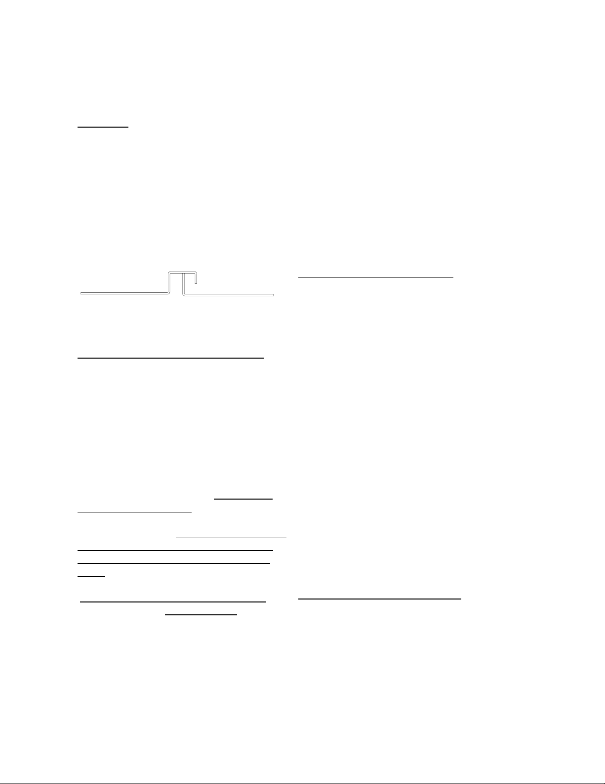
LEVELING and SEALING
–
Proper drainage of the evaporator
condensate water requires the cabinet to
be properly leveled. This means left to
right as well as front t o back.
The case can be leveled using the
leveling screws in the bottom of the case
or by shimming under the cabinet base
frame. The self-closing doors require the
cabinet to be properly leveled. End to end
leveling will make the doors close with
uniform speed and tightness. Once level
the case should be sealed to the floor as
shown in the f ollowing drawing, using an
NSF approved material such as General
Electric RTV-102 silicone sealer or an
equivalent.
Silico ne Sealant
Floor
BOTTOM LOUVERED PANEL
REMOVAL –
The louvered panel provides access to the condens ing unit and the electrical box. The panel is secured with
screws to prevent injury.
COMPRESSOR
–
The compress or is banded for
s hippi ng . T HE BA N D MU S T B E R EMOVED. The mounting bolts on the
compressor are factory pre-set to allow
the compressor to float freel y on the
mounting springs. DO NOT LOOSEN
NUTS.
CABI NET DRA IN
–
A positive pitched drain tube is
factory-installed which runs to a drain
pan in the condensing unit area from
the evaporator se ction to handle defrost
water. No piping to a floor drain is necessary but the tube should be checked
to make sure the tube has not become
plugged with items such as pricing
stickers, and is over the pan so water
does not run onto the floor.
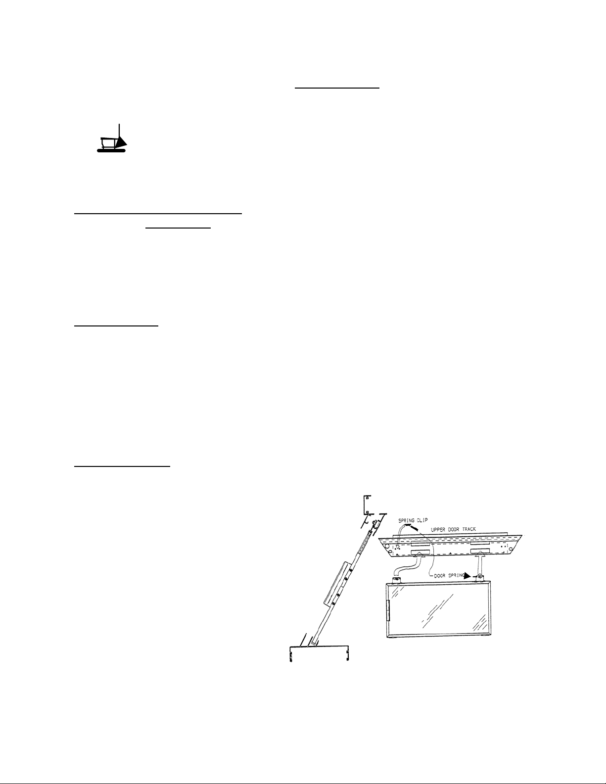
GLASS DOORS –
The doors are made of tempered,
heat reflective glass. The doors mount in
the aluminum top canopy. The bot tom
tr acks are provi ded with wipe outs for
cleaning purposes.
The doors are self-closing and are
supported by rollers that ride on the upper
track. The upper track has cut out areas to
insert the door rollers up into. The door
spring is then slipped over a clip at the end
of the track. Prior to November, 1997 the
upper track also has a ‘bounce back’ spring
mounted to each end to assist the door in
sealing when it closes. There is a thumbscrew on the end of the spring that allows
for adjustment of the amoun t of ‘bounce
back’. Turning the screw ‘in’ will allow
for more ‘ bounce back’.
Cas es produced starting November
1997 eliminate the spring back mechanism
and have rubber channels in the end frames
to grab and seal the door upon cl osing. As
always, proper cleaning of d oor rollers and
tracks is required for proper door operation.
SHELVES
–
The five solid shelves that set
over the evaporator section must be installed
as shown below otherwise the air will not
flow through the cas e and the novelty baskets
will not set in the case correctly.
Example in the diagram below
CABINET AREA
PAN
COIL & FAN AREA
PAN
AIR DISTRIBUTION AND PRODUCT
If desired an optional kit utilizing
twenty-one baskets in place of the fifteen baskets supplied with the cabinet may be ordered. This kit consists of baskets (which are
different size than the fifteen standard ones
supplied with the cabinet) and two shelf covers. The shelf covers, when properly installed over the five solid metal shelves, create a smooth flat surface allowing the use of
additional baskets. When utilizing this kit,
the five solid s helves must be left properly
ins talled as shown above, and the opti onal
covers placed over the shelves with the
formed edges down. If all shelves and covers
are not properly installed, interior airflow
and temperature in the cabinet will be affected.
AIR DISTRIBUTIO N AND PRODUCT
and LOADING
The GIM-6 is a ‘forced-air” cabinet
employing a state-of-the-art honeycomb air
discharge system. Air is discharged from the
honeycomb, flows over the top of the product,
and is returned throug h the return air duct.
The interior of the cabinet has load line
markings showing how high product can be
loaded in the cabinet without affecting the air
curtain. White, epoxy-coated, wire baskets are
provided for the product and they are designed
to fit below the load line. DO NOT LOAD
PRODUCT ABOVE THE LOAD LINE AS IT
WILL ADV ERSE L Y AFFECT CAB INET
TEMPERATURE.
ELE CTRI CA L CONNE CTION S
–
It is very important for safety to you and
your customers to have the cabinet properly
grounded.
The e lectric al installation should be done
by a qualified electrician in accordance with the
National Electrical Code and/or local codes.
NOTE: Connecting this unit to
any electrical supply other than
specified on the serial plate will
void the warranty and may res ult
in serious damage to the unit. The
cabinet should be supplied with its
own service.
Pr ior to performing any s ervice or maintenance on this cabinet, be sure to disconnect the
power supply to the cabinet. Failure to do so
may result in electrical shock and/or serious inju ry .
SERI AL PLAT E I NFORMA TION
–
The serial plate is located in the upper
left hand corner of the case interior. It has all
the pertinent information needed for proper
el ectric al installati on. The serial plate should
not be removed for any reason.
 Loading...