

Page 1
B
D
G
E
F
C
A
H
E
P/N0465900F
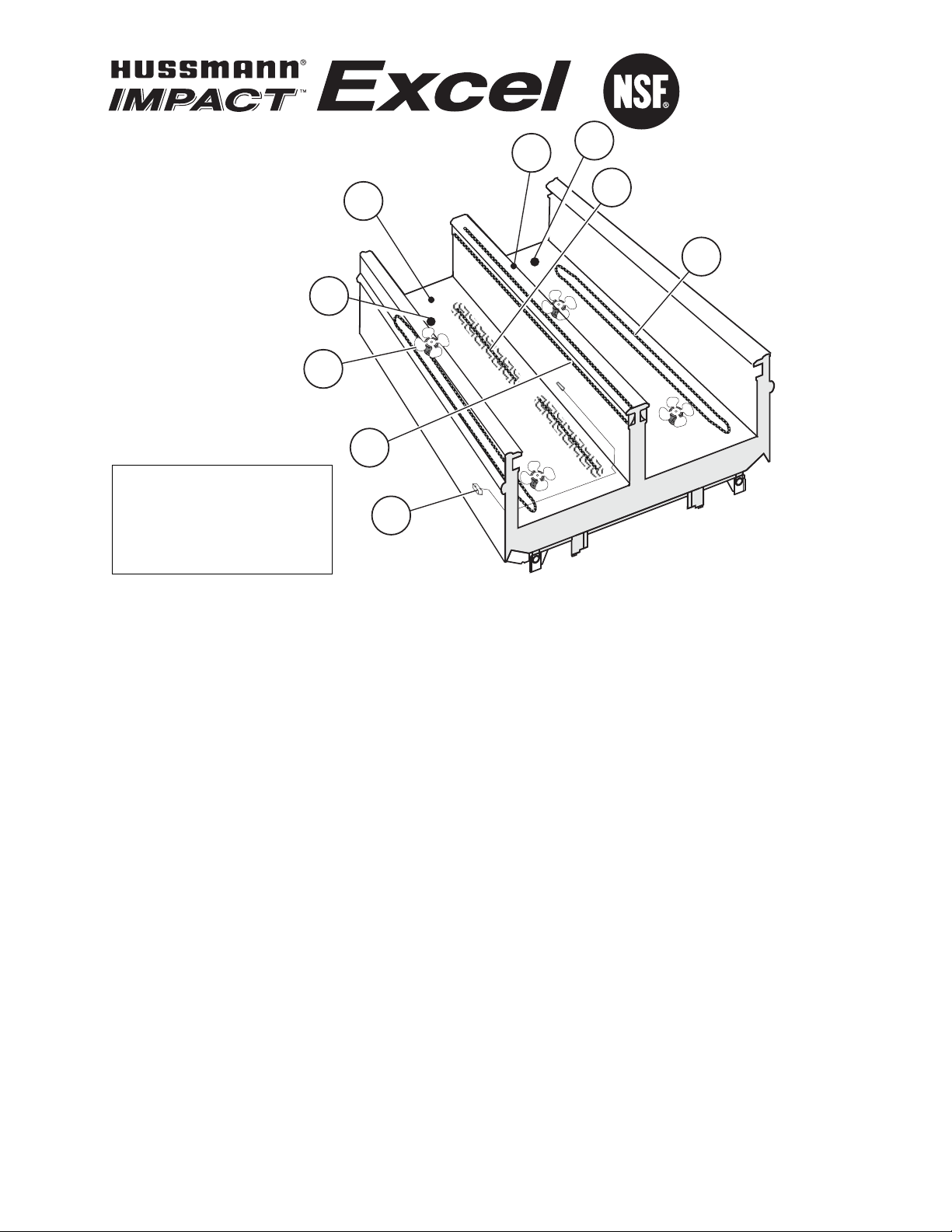
Item Part # Description Wiring Item #
FAN ASSEMBLIES, AND THERMOSTATS
A. 4W Standard Fan Assembly (1)
0392457 Fan Motor, Evaporator
(MO.4410101)
0464847 Fan Blade (FB.4780649)
4W Energy Efficient Fan Assembly (1)
0477653 Fan Motor, Evaporator
(MO.4410544)
0464847 Fan Blade (FB.4780649)
B. Optional Adjustable Refrigeration Thermostat (2)
C. 0398557 Defrost Termination Thermostat (3)
(Front/Electric Defrost only)
(CT.4440611)
D. 0398558 Defrost Termination Thermostat (3)
(Rear/Electric Defrost only)
(CT.4481088)
E. 0481370 Heater Switch (4)
(Koolgas Defrost only)
(CT.4440738)
Item Part # Description Wiring Item #
H
EATERS
F. 208V Evaporator Defrost Heaters (5)
0481864 4 ft case (HE.4850637)
0462159 8 ft case (HE.4850603)
0444058 12 ft case (HE.4850571)
G. 208V Drip Pan Defrost Heaters, Electric (6)
0481865 4 ft case (HE.4850638)
0462160 8 ft case (HE.4850636)
0444296 12 ft case (HE.4850572)
120V Drip Pan Defrost Heaters, Koolgas (7)
0488967 4 ft case (HE.4850641)
0465907 8 ft case (HE.4850622)
0465908 12 ft case (HE.4850623)
H. Nosing Anti-sweat Heaters (8)
0495009 4 ft case (HE.4850687)
0495007 8 ft case (HE.4850685)
0495008 12 ft case (HE.4850686)
We reserve the right to change or revise
specifications and product design in
connection with any feature of our
products. Such changes do not entitle
the buyer to corresponding changes,
improvements, additions or replacements
for equipment previously sold or shipped.
FW
Technical Data Sheet
P/N 0465900_F
NSF
®
Certified
Mach 2010
©2010 HUSSMANN CORPORATION • BRIDGETON, MO 63044-2483 U.S.A.
U.S. & CANADA 1-800-922-1919 • MEXICO 1-800-522-1900 • WWW.HUSSMANN.COM
Note: Revision F adds 6 ft length.
Page 2
2 of 7 FW Technical Data Sheet
U.S. & CANADA 1-800-922-1919 • MEXICO 1-800-522-1900
10 1/4
(261)
4 3/4 (120)
15 3/4
(400)
FRONT
C
Splashguard
12 1/8 (307)
A
B
D
Splashguard
8 1/2 (217)
Waste Outlet
29 1/2
(750)
Refrigeration
Outlet
Waste
Outlet
Waste
Outlet
80 5/8
(2046)
72
(1829)
64 1/2
(1638)
70 1/4
(1784)
59 3/4
(1515)
Electrical
Field
Connection
26 1/2 (673)
Wireway
Electrical
Stub Up Area
6 x 6
(152 x 152)
8 (203)
41 1/2
(1054)
43 7/8
(1114)
41 1/2
(1054)
4 1/4 (108)
4 1/2 (115)
Waste Outlet
20 3/4
(529)
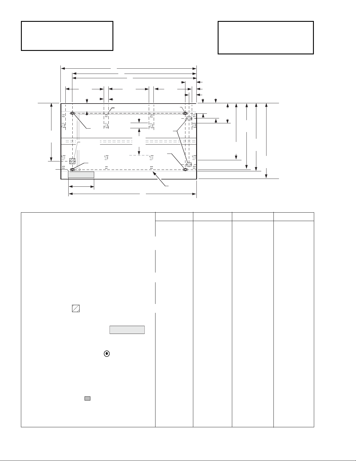
Engineering
Plan Views
Dimensions shown as inches & (mm).
10-2004
Low / Medium Temperature
Wide Island
PHYSICAL DATA
Merchandiser Drip Pipe (in.) 1 1/4
Merchandiser Liquid Line (in.)
3
/8
Merchandiser Suction Line (in.)
5
/8
(12 Ft shown)
4 ft 6 ft 8 ft 12 ft
General
(A) Case Length (without ends or partitions) 48 1/4 (1226) 73 3/4 (1874) 96 3/8 (2448) 144 1/2 (3670)
(Each end and insulated partition adds 2 in. (51 mm) to case line up.)
Maximum O/S dimension of case back to front (includes bumper)
80 5/8 (2046) 80 5/8 (2046) 80 5/8 (2046) 80 5/8 (2046)
Back of case to front of splashguard 72 (1829) 72 (1829) 72 (1829) 72 (1829)
Back of case to O/S edge of front leg 59 3/4 (1515) 59 3/4 (1515) 59 3/4 (1515) 59 3/4 (1515)
Distance between edges of external legs and center legs NA 30 1/4 (768) 41 1/2 (1054) 41 1/2 (1054)
Distance between edges of center legs NA NA NA 43 7/8 (1114)
Distance between front legs and splashguard 12 3/
8 (312) 12
3
/
8 (312) 12
3
/
8 (312) 12
3
/
8 (312)
Electrical Service (Electrical Field Wiring connection point)
(B) RH End of case to center of stub up area 36
1
/8 (918) 61 5/8 (1565) 84 1/4 (2140) 132 3/8 (3363)
Back of case to center of stub up area 64 1/2 (1638) 64 1/2 (1638) 64 1/2 (1638) 64 1/2 (1638)
Length of electrical wireway 26
1
/2 (673) 26 1/2 (673) 26 1/2 (673) 26 1/2 (673)
(C) RH End of case to LH end of wireway 40
1
/2 (1029) 67 1/2 (1715) 90 1/8 (2289) 138 1/4 (3511)
Waste Outlets (One each end)
(D) RH End of case to the center of LH waste outlet 36 1/8 (918) 61 5/8 (1565) 84 1/4 (2140) 132 3/8 (3363)
RH End of case to the center of RH waste outlet 12 1/8 (307) 12 1/8 (307) 12 1/8 (307) 12 1/8 (307)
Back O/S of case to center of waste outlets 70
1
/4 (1784) 70 1/4 (1784) 70 1/4 (1784) 70 1/4 (1784)
Schedule 40 PVC drip pipe 1
1
/4 (32) 1 1/4 (32) 1 1/4 (32) 1 1/4 (32)
Refrigeration Outlet
Back of case to center of front refrigeration outlet 64 7/8 (1646) 64 7/8 (1646) 64 7/8 (1646) 64 7/8 (1646)
Back of case to center of rear refrigeration outlet 15 3/4 (400) 15 3/4 (400) 15 3/4 (400) 15 3/4 (400)
RH end of case to center of refrigeration outlet 8 (203) 8 (203) 8 (203) 8 (203)
Wireway
Page 3
REFRIGERATION DATA
Note: This data is based on store temperature and
humidity that does not exceed 75°F and 55% R.H.
MED FF IC
Discharge Air (°F) +24 –12 –22
Evaporator(°F) +19 –20 –30
Unit Sizing (°F) +17 –23 –33
Btu/hr/ft * M
ED FF IC
Parallel 415 530 575
Conventional 430 550 600
*Optional energy efficient motors reduce the
refrigeration load by 27 Btu/hr/ft (4 ft and 8 ft models)
and 18 Btu/hr/ft (12 ft models).
DEFROST DATA
MED FF IC
Frequency (hr) 24 24 24
Defrost Water (lb/ft/day) 1.6 1.5 1.2
(± 15% based on case configuration and product
loading).
E
LECTRIC
M
ED FF IC
Temp Term (°F) 48 48 48
Failsafe (minutes) 60 60 60
GAS
Duration (minutes) NA 15 18
O
FFTIME Not Recommended
Standard Defrost Thermostat
Close on rise: close 48°F — open 33°F
CONVENTIONAL CONTROLS
Low Pressure Backup Control — CI/CO **
M
ED +22°F / +10°F
FF –17°F / –29°F
IC –27°F / –39°F
Indoor Unit Only, Pressure Defrost Termination**
Not Recommended
**Use a Temperature Pressure Chart to determine
PSIG conversions.
Estimated Charge ***
4 ft 1.7 lb 27 oz 0.8 kg
6 ft 2.1 lb 34 oz 1.0 kg
8 ft 2.5 lb 40 oz 1.1 kg
12 ft 3.7 lb 59 oz 1.7 kg
***This is an average for all refrigerant types. Actual
refrigerant charge may vary by approximately half a
pound.
3 of 7P/N 0465900_F
HUSSMANN CORPORATION • BRIDGETON, MO 63044-2483 U.S.A. • WWW.HUSSMANN.COM
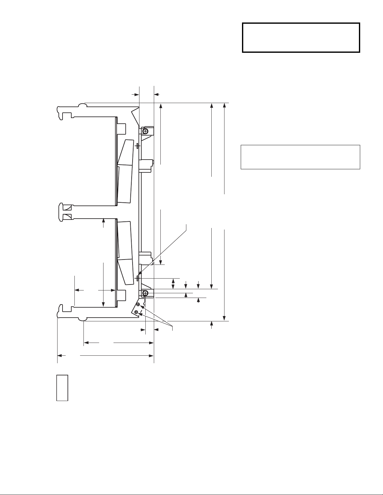
FAN
COIL
15
1
/4
(388)
35
7
/8
(910)
33 (838)
5
1
/2
(140)
3
1
/8
(79)
26
3
/8
(669)
COIL
FAN
Refrigeration
Outlet
59
3
/4 (1515)
11
3
/4 (299)
68
7
/8 (1747)
80
5
/8 (2046)
3
1
/4 (82)
1
1
/2 (37)
4 (101)
FW
Case-to-Case
Connection
Impact
Excel
FW
Low / Medium Temperature
Wide Island Display with Solid Walls
Dimensions shown as inches & (mm).
NSF Certification
This merchandiser model is manufactured to meet ANSI/NSF
(National Sanitation Foundation) Standard #7 requirements for
construction, materials & cleanability.
Page 4

FW Technical Data Sheet
U.S. & CANADA 1-800-922-1919 • MEXICO 1-800-522-1900
4 of 7
Impact
Excel
FW
Low / Medium Temperature
Electrical Data
4 ft 6 ft 8 ft 12 ft
Number of Fans – 4W Evaporator 2 2 4 4
Amperes Watts
4 ft 6 ft 8 ft 12 ft 4 ft 6 ft 8 ft 12 ft
Evaporator Fans
120V 60Hz Standard 0.62 0.62 1.24 1.24 48 48 96 96
120V 50Hz Standard 0.76 0.76 1.52 1.52 54 54 108 108
230V 60Hz Export 0.30 0.30 0.60 0.60 48 48 96 96
230V 50Hz Export 0.36 0.36 0.72 0.72 54 54 108 108
120V 60Hz Energy Efficient 0.24 0.24 0.48 0.48 16 16 32 32
230V 60Hz Energy Efficient 0.12 0.12 0.24 0.24 16 16 32 32
Anti-sweat Heaters (on fan circuit)
120V 50/60Hz Standard 0.67 1.00 1.33 2.00 80 120 160 240
230V 50/60Hz Export 0.35 0.52 0.70 1.04 80 120 160 240
Minimum Circuit Ampacity
120V 60Hz Standard 1.49 1.82 2.77 3.44
120V 50Hz Standard 1.63 1.96 3.05 3.72
230V 60Hz Export 0.85 1.02 1.50 1.84
230V 50Hz Export 0.91 1.08 1.62 1.96
120V 60Hz Energy Efficient 1.11 1.68 2.01 2.68
230V 60Hz Energy Efficient 0.67 0.84 1.14 1.48
Maximum Over Current Protection 120V 20 20 20 20
Maximum Over Current Protection 230V 15 15 15 15
208V Electric Defrost 8.75 13.07 15.38 23.07 1820 2720 3200 4800
230V Export Electric Defrost 7.91 11.83 13.91 20.87 1820 2720 3200 4800
120V Koolgas Defrost 2.50 2.67 3.33 6.66 300 320 400 800
Standard Lighting
None
Page 5
5 of 7P/N 0465900_F
HUSSMANN CORPORATION • BRIDGETON, MO 63044-2483 U.S.A. • WWW.HUSSMANN.COM
Impact
Excel
FW
Low / Medium Temperature
ESTIMATED SHIPPING WEIGHT
5
Case Solid End
4 ft 6 ft 8 ft 12 ft (each)
lb (kg) 1000 (454) 1200 (544) 1400 (635) 1600 (726) 75 (34)
5
Actual weights will vary according to optional kits included.
Product Data
Recommended Usable Cube
1
(Cu Ft/Ft) 6.99 ft3 /ft (0.65 m3 /m)
AHRI Total Display Area
2
(Sq Ft/Ft) 5.50 ft2/ft (1.68 m2/m)
Shelf Area 3(Sq Ft/Ft) 5.50 ft2/ft (1.68 m2 /m)
1 AHRI Refrigerated Volume less shelving and other unusable space: Refrigerated Volume/Unit of Length, ft
3
/ft [m3/m]
2
Computed using AHRI 1200 standard methodology: Total Display Area, ft2[m2]/Unit of Length, ft [m]
3
Shelf surface area is composed of bottom deck plus standard shelf complement, as shown in the Hussmann
Product Reference Guide. The standard shelf complement for this model is NONE
.
Page 6

6 of 7
Red
Electric Defrost Heaters
Drip Pan Heater
6
Red
5
208 V Power From
Defrost Contactors
L1
L2
Red
Electric Defrost Heaters
Drip Pan Heater
6
Red
5
Defrost Termination Thermostat
Dark Blue
To
Condensing Unit
}
3
Light Blue
2
To
Condensing Unit
}
Refrigeration Thermostat (Optional)
1
BROWN BAND
Fans
BROWN BAND
Nosing Anti-sweat Heaters
120V POWER
120V NEUTRAL
8
WARNING
All components must have mechanical ground, and the merchandiser must be grounded.
Circled Numbers = Parts List Item Numbers
1
BROWN BAND
BROWN BAND
8
Electric Defrost – Standard
4 Ft - 2 Fans
6 Ft - 2 Fans
8 Ft - 4 Fans
12 Ft - 4 Fans
FW Technical Data Sheet
U.S. & CANADA 1-800-922-1919 • MEXICO 1-800-522-1900
Page 7
7 of 7P/N 0465900_F
HUSSMANN CORPORATION • BRIDGETON, MO 63044-2483 U.S.A. • WWW.HUSSMANN.COM
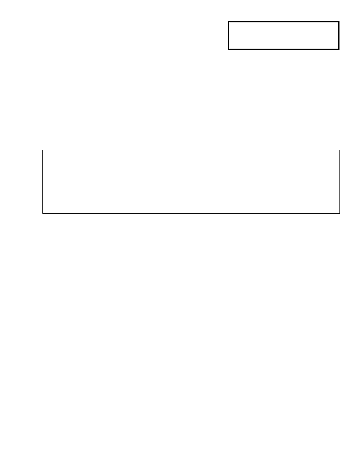
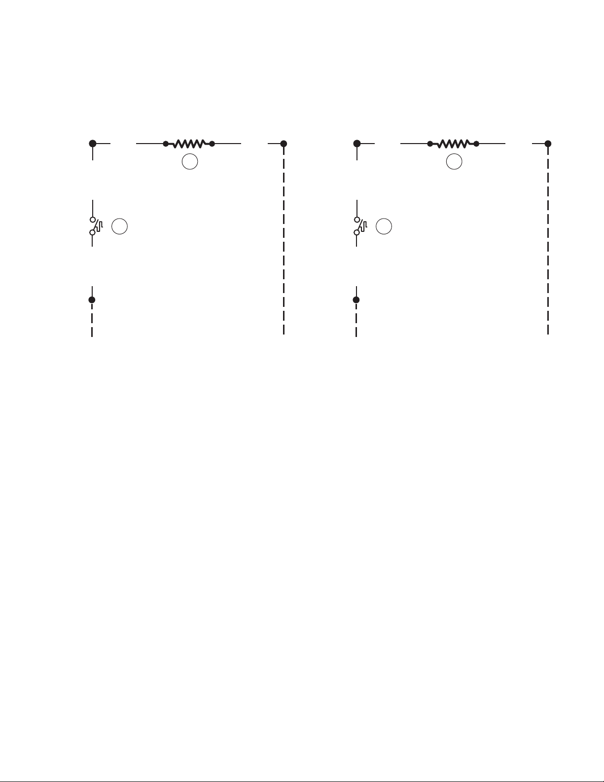
Gas Defrost – Optional
WARNING
All components must have mechanical ground, and the merchandiser must be grounded.
Circled Numbers = Parts List Item Numbers
Grayed components in 12 foot models only.
7
4
120V Drip Pan Heater — Koolgas Only
Yellow
Heater Switch
Yellow
120V
POWER
120V
NEUTRAL
Dark Blue
Dark Blue
7
4
Yellow
Heater Switch
Yellow
120V
POWER
120V
NEUTRAL
Dark Blue
Dark Blue
 Loading...