

Page 1
Chromalox
®
DIVISION 4 SECTION
SALES
REFERENCE
DATE
SERVICE REFERENCE
PD447-2
161-304262-001
DECEMBER, 2004
Installation Instructions
(Supersedes PD447-1)
© 2010 Chromalox, Inc.
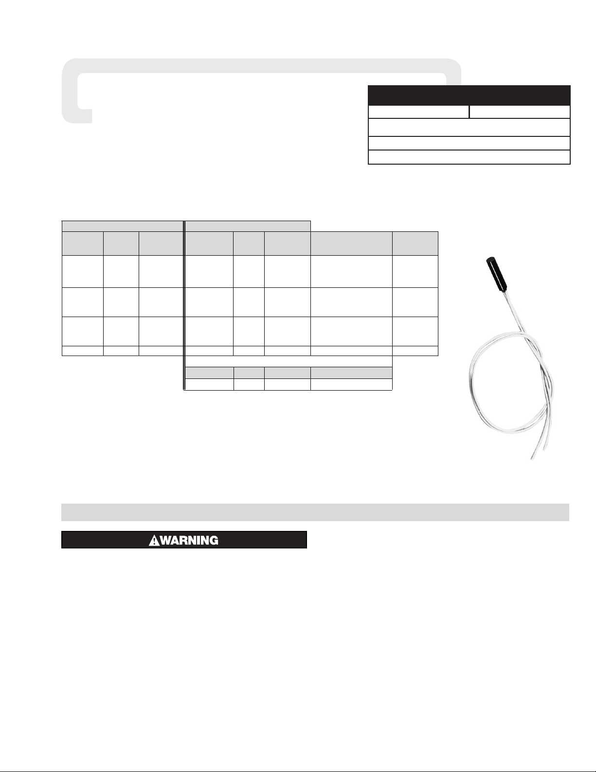
Replacement Thermal Fuses
For Use on Products Listed in Table Below
Model No. PCN Temp. Products Used on
RFM-EC 360321 All All
Note: Single fuse rated to 240V, 25A cold. Resettable fuse rated to 240 V, 5 A cold.
1
Standard fuse from factory for product types listed in box to right.
2
Resettable fuse is bi-metal switch only and requires connection to Resettable Fuse System Circuitry, model
RFM-EC, PCN 360321 which must be ordered separately. RFM-EC includes Manual Reset, Audible Alarm and
Relay rated to 240 V, 5 Amp.
3
Process temperature of solution must always be a minimum of 30˚F below Fuse Temperature Limit.
4
For fluoropolymer series process temperatures over 180˚F, consult factory. (GTF / GXF Series)
5
For QM Series process temperatures above 230˚F, consult factory.
Resettable Fuse System Circuitry
2
Fuse Temp. Fuse Temp. Lead
Model No. PCN Limit (˚F)
3,4,5
Model No.2PCN Limit (˚F)
3,4,5
Applicable Products Length (in)
F 360330 219 RF 360436 219 18
FM
1
360348 262 RFM 360444 262 GS, GT, GS3, GT3 18
FH 360356 330 RFH 360452 330 18
FT 360364 219 RFT 360460 219
GTF, GTFL, GXF 18
FTM
1
360372 262 RFTM 360479 262
GTF6, GTF9, 18
QM, QM3 18
FL 360399 219 RFL 360495 219 GSL, GTL, 86
FLM
1
360401 262 RFLM 360508 262 GSL3, GTL3, 86
FLH 360410 330 RFLH 360516 330 GSV3, GTV3 86
FLT 224717 219 RFLT 224725 219 GTFL, GXFL, GTFL3 86
Single Use Fuse Resettable Fuse
2
INSTALLATION
ELECTRIC SHOCK HAZARD. Disconnect all power
to heater before replacing Fuse. Failure to do so
could result in personal injury or death.
The thermal fuse device must be properly installed and these procedures must be followed or heater failure or fire may result.
A liquid level control is required as an additional safety fea-
ture to help minimize the possibility of fire.
1. Insure all electrical power to the heater is shut-off.
2. Unscrew the terminal head cover. Remove the wire nuts from
the fuse leads and save for reuse.
3. Remove the sealing material and pull the fuse out of the
well. Save the sealing material for reuse.
4. Check the fuse and the inside of the well for wetness. If
wet, the well must be dried out. We recommend using a heat
gun or hair dryer. Immerse the tube into the solution. If moisture again appears inside the well, DO NOT use the heater!
Call your local Chromalox representative for further advice.
5. If the removed fuse is dry, proceed by using it as a guide to
cut and strip the new fuse lead wires to the correct lengths.
6. Reconnect the fuse leads to the extension leads using the original
wire nuts.
7. Reinsert the fuse into the well making sure it is fully seated to
the bottom of the well.
8. Reseal using the original sealing material or an RTV type
sealant.
9. Replace the head cover, return the heater to the tank.
10. Turn power back on.
Thermal Fuse Temperature System —
Grounded electric immersion heaters are practical, efficient
and safe when used properly and installed in tanks that have proper solution levels, good ventilation, trained operators and safeguards such as liquid level controls and Chromalox thermal fuse
over-temperature sensors.
Chromalox thermal fuse systems help reduce the hazards created
by low liquid levels and when properly seated and wired, they will
cut off the power to the heaters, thus avoiding the high temperatures
resulting if solution levels are low enough to expose heater hot zones.
Page 2
TA - Q0 - EF
Litho in U.S.A.
2150 N. RULON WHITE BLVD., OGDEN, UT 84404
Phone: 1-800-368-2493 www.chromalox.com
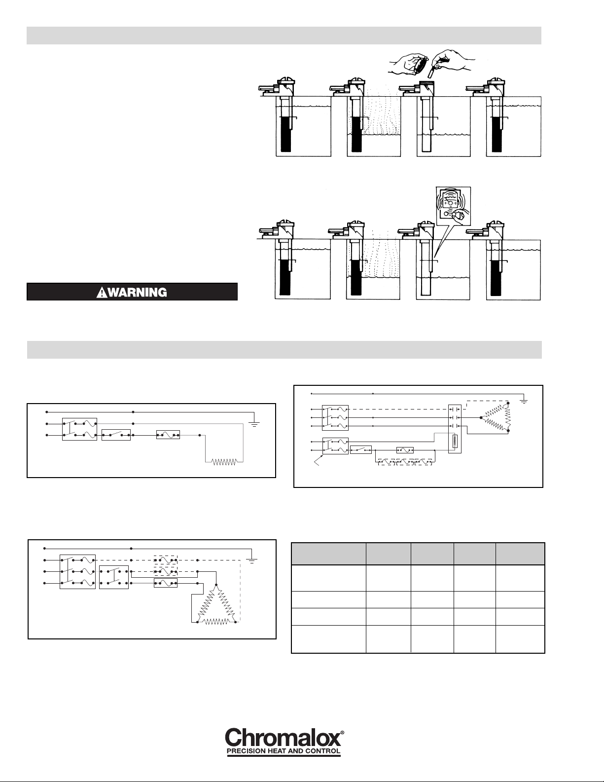
Tank with normal
solution level. System
working normally.
Tank has low solution
level, system shuts
off power to heater.
Alarm sounds. Proper
solution level is restored
and system is reset.
Normal operation
resumed.
THERMAL FUSE INSTALLATION/REPLACEMENT
Single Use System —
Sensor consists of a one-time thermal fuse which is stan-
dard on the over-the-side metal, Teflon
®
and quartz heaters,
and L-shaped metal and Teflon
®
heaters, listed in the table on
page 1.
The thermal fuse is wired in series with the controller. To
operate properly, the fuse must be fully seated to the bottom of
the thermowell tube. When the fuse blows, shut off the main
power to the heater, remove the spent fuse, install the new one,
then refill the tank. Turn power back on. Replacement thermal
devices must be purchased from Chromalox.
Resettable Fuse System —
Sensor consists of a Bi-metallic thermostatic sensor, an
audible alarm, alarm relay, and reset button. This option is
available on metal, Teflon
®
and quartz heaters, as listed in the
table on page 1.
The system operates on the same principle as the single
use fuse except that the sensor does not blow. It operates as
a Bi-metallic thermostat which opens and sounds the alarm.
The reset button must be pushed to re-activate the heater
and control after the solution level in the tank has been
raised to the proper level.
In both of the above cases make sure the
cause of the failure has been determined and
corrected.
Single Use System
Resettable Fuse System
WIRING
Representative wiring diagrams for heaters with Thermal Fuses —
Single phase heater circuit using a SPST thermostat. Line
Voltage and/or current do not exceed thermostat or thermal fuse
rating (Figure A).
One Single phase heater or (3) single phase heaters equal in
size and each having a thermal fuse wired as a 3 phase heater circuit using a DPST thermostat. Line voltage and current do not
exceed thermostat or thermal fuse(s) rating (Figure B). Dotted
line and L3 indicate 3 phase connections.
Single phase or 3 phase heater circuit. Line voltage and/or
current exceeds thermostat or thermal fuses ratings (Figure C).
Dotted line and L3 indicate 3 phase connections.
Thermal Fuse Electrical and Temperature Ratings —
Electrical Ratings:
Single Use Fuses rated at 25 amps, 240 VAC max.
Resetable Fuses rated at 5 amps, 240 VAC max.
Ground
L2
Thermostat
Thermal Fuses
Black
Black
Green
Fused
Disconnect
(Customer Supplied)
*
*
*
*
*
*
L3
L1
Heater
Black
Figure B
Ground
L2
L1
Thermostat
Thermal Fuse
Heater
Black
Black
Green
Fused
Disconnect
(Customer Supplied)
**
Figure A
Fused Disconnect
(Customer Supplied)
Ground
L3
L2
L1
L2
L1
*
*
Thermostat
Thermal Fuses
Magnetic
Contactor
Black
Black
Heater
Black
Green
Figure C
Tank has low solution level, fuse shuts
off power to heater.
Spent fuse removed,
new fuse installed.
Proper liquid level
restored and normal
operation resumed.
Tank with normal
solution level. Fuse
system on heater
working normally.
Heater
Single Use Reset
Temp.
Process
Wire Color Wire Color Temp.
GS, GT,
White White 219 <180
GS3, GT3
Blue Blue 262 <230
Red Red 330 <300
QM, QM3
Red White 219 <180
Blue Blue 262 <230
GTF, GTFL, GXF, GXFL
Red White 219 <180
GTF6, GTF9, GTFL3
GSL, GTL or White White 219 <180
GSL3, GTL3 or Blue Blue 262 <230
GSV3, GTV3 Red Red 330 <300
Limited Warranty:
Please refer to the Chromalox limited warranty applicable to this product at
http://www.chromalox.com/customer-service/policies/termsofsale.aspx.
 Loading...