

Hussmann ESC Installation And Operation Manual
Manual
Installation
& Operation
/Chino
ESC
REV. 0303
DELI/MEAT/FISH SERVICE CASE
ESC
DELI/MEAT/FISH SERVICE CASE
P/N IGSV-ESC-0303
INSTALLATION & OPERATION GUIDE

General Instructions
Ta b l e of Contents
General Instructions ................................................. 2
SHIPPING DAMAGE............................................................................................... 2
Important Information ............................................. 3
Cut & Plan Views ....................................................... 4
Installation ................................................................. 5
LIFT-UP GLASS RE-ADJUSTMENT .......................................................................... 5
LEVELING.............................................................................................................. 5
Glass Adjustment ...................................................... 8
Plumbing .................................................................... 9
WASTE OUTLET AND P-TRAP .............................................................................. 9
Manifold Flush System ............................................. 9
Humidity System ...................................................... 10
Refrigeration ............................................................. 12
T-STAT LOCATION.................................................................................................. 12
Electrical .................................................................... 13
WIRING COLOR CODE ......................................................................................... 13
ASHRAE COLOR CODE .......................................................................................... 13
Finishing Touches ...................................................... 14
JOINT TRIM........................................................................................................... 14
User Information ...................................................... 15
STOCKING.............................................................................................................. 15
CASE CLEANING.................................................................................................... 15
Lift Up Glass .............................................................. 17
Maintenance .............................................................. 23
ELECTRICAL PRECAUTIONS ................................................................................... 23
REPLACING FLUORESCENT LAMPS ....................................................................... 23
TIPS & TROUBLESHOOTING ................................................................................. 23
Case Specifications ................................................... 24
Electrical Schematics ............................................... 25
Appendices ................................................................ 36
APPENDIX A. – Temperature Guidelines ............................................................ 36
APPENDIX B. – Application Recommendations .................................................. 36
APPENDIX C. – Field Recommendations -......................................................... 36
APPENDIX D. – Recommendations to user - .................................................... 37
IGSV-ESC-0303
THIS BOOKLET CONTAINS INFORMATION ON:
ESC: European-style Refrigerated Service Case for Deli,
Meat, Fish, and matching Refrigerated Wedges.
**NOTE: Be sure to read the “Important Information”
secion for proper case operation, before loading the
merchandiser.
SHIPPING DAMAGE
All equipment and separately packaged accessories
should be carefully removed, and thoroughly examined
for shipping damage during unloading. This equipment
has been carefully inspected at our factory, and the
carrier has assumed responsibility for it's safe arrival.
If it is indeed damaged, either apparent or concealed a claim must be filed with carrier. If there is obvious loss
or damage, it must be noted on the freight bill or
express receipt, and signed by the carrier’s agent;
otherwise, carrier may refuse claim. The carrier will
supply the necessary claim forms. When loss or damage
is not apparent until after all equipment is uncrated, a
claim for concealed damage is made. Make request in
writing to carrier for inspection within 15 days. Retain
all packaging. The carrier will supply inspection report
and required claim forms. Check your shipment for any
possible shortages of material. If a shortage should exist
and is found to be the responsibility of Hussmann Chino,
notify Hussmann Chino. If such a shortage involves the
carrier, notify the carrier immediately and request an
inspection. Hussmann Chino will acknowledge shortages
within ten days from receipt of equipment.
HUSSMANN CHINO PRODUCT CONTROL
The serial number and shipping date of all equipment
is recorded in Hussmann's files for warranty and
replacement part purposes. All correspondence
pertaining to warranty or parts ordering must include
the serial number of each piece of equipment involved,
in order to provide the customer with the correct parts.
Keep this booklet with the case at all times for future reference.
/Chino
A publication of
Hussmann® Chino
13770 Ramona Avenue • Chino, California 91710
(909) 628-8942 FAX
(909) 590-4910
(800) 395-9229
The Hussmann warranty is printed in the back of
this guide.
2

Rev. 0303
Important Information
The ESC service cases are easy to work, attractive
merchandising display cases capable of maintaining superb
product quality, with the installation of the proper
controlling devices. These should be set according to the
manufacturer’s specifications and combined with a properly
maintained humidity system. Incorrect settings and failure
to maintain the humidity system will result in short product
life from dehydration, shrinkage and discoloration. Below
are a few guidelines to ensure optimum performance and
product life.
•Review the Case Specification in this book to verify
thermostat setting. Do not set temperature too cold,
as this causes product dehydration.
•Temperatures should be achieved by a t-stat and
suction solenoid at each case. Do not use EPR valves,
liquid line solenoids or electronic control devices of
any kind. These controls allow temperature
swings causing product dehydration and
excessive energy consumption.
•Defrost cycles should be set according to the Case
Specifications in this book
•Clean humidity system a minimum of every 90 days
for proper system operation.
•Work and rotate product – not to exceed a four (4)
hour period.
•At night turn off case lights and cover product with
moistened cheesecloth or fabric towels.
•Keep meat holding box at 32°.
•Keep meat prep room refrigerated at 55°.
• Meat bloom box (if applicable) should be at 36°.
• Meat must enter the case at 40° or below. Product
deterioration is very rapid above 40°.
•Maintain sanitary conditions throughout the meat
holding, prep and working areas.
•Do not display product directly within the air
discharge.
• Turn and rotate the meat. The blood which
gives the pink color works down in time which
causes surface discoloration and dehydration.
When turned before this condition occurs the
other side is kept in good color (bloom)
condition. The meat can even be turned (3)
three and (4) four times.
• It is not required at night to remove the
product from the case. Turn the lights off at
night and cover the product. We recommend
you use a moistened cheesecloth or towels.
This helps slow down the product dehydration
process by taking the moisture from the cloth
and not from the product. This is an old
method that meat shops have used for many
years. It works and helps to gain extended
product life.
• Cold coils remove heat and moisture from the
case and deposit it as frost on the coil. Thus a
defrost is required to remove this frost. Our
humidity system adds moisture to the case and
helps slow down the dehydration process. The
only other moisture in the case is in the
product. A single level of meat in a case will
dry out much faster than a fully loaded case
with three to four levels of meat.
• The colder the case, the faster the product
loses its moisture and shelf life. It is very
important to maintain a constant even
product temperature (see Case
Specifications).
3

Light
IGSV-ESC-0303
Cut & Plan Views
1
2
3
/
4
"
6"
Optional St. Steel Slanted
Deck Pan (Meat/Fish)
/8"
3
36"
1/4"
7
(4 1/4")
45
"
8
/8"
1
1
11
1
10
/2"3
43
1"
5
/8"
1
2
ESC
Service
Scale = 1/2"
8"
8"
DRAIN
MECHANICAL
STUB UP AREA
19" X 19"
1" 1"
CASE FRONT
8'-2"
(VARIABLE LENGTHS)
WATER,
ELEC. &
REFRIG.
MECHANICAL
STUB UP AREA
19" X 19"
ESC
Plan View
Scale = 1/4"
1
1
C
S
E
le
b
ria
a
V
s
th
g
n
e
L
FRONT
30° INSIDE WEDGE
Light
6
1
/4"
7
6
/4")
1
(4
Raceway
1
/4"
"
Water
Optional St. Steel
Slanted Deck
/8"
3
Pan (Meat/Fish)
36"
34
PEDESTAL
OPTION
/4"
1
11
/2" 26"
43
5
/8"
ESC
Pedestal Option
Scale = 3/8"
"
8
/
5
43
3
1
3
"
1
4
/
/
4
"
R
L
ESC
Var i
able
Lengths
"
4
/
3
ESC
3
Var i
able
4
"
4
/
3
3
4
Lengths
1
1
L
3
/
4
"
FRONT
C
S
E
le
b
ria
a
V
s
th
g
n
e
L
R
3
"
4
/
1
1
30° OUTSIDE WEDGE
"
3
4
/
7
1
L
C
S
E
e
l
b
a
i
r
"
s
a
h
V
t
4
g
/
n
e
L
3
3
4
FRONT
45° INSIDE WEDGE
4' - 11 1/4"
"
4
/
3
17
L
ESC
Var iable
Lengths
23
FRONT
INSIDE WEDGE
C
90°
1
7
3
/
4
"
R
E
S
C
V
a
r
i
a
b
L
l
e
e
n
g
t
h
s
E
S
C
V
a
r
i
a
b
L
l
e
e
n
g
t
h
s
R
L
1
7
3
FRONT
3
4
/
/
7
4
"
1
4
3
3
/
4
"
C
S
E
e
l
b
a
i
r
s
a
h
V
t
g
n
e
L
"
45° OUTSIDE WEDGE
17
3
/
4
"
R
ESC
Var iab le
Lengths
"
43
ESC
Var iab le
Lengths
17
"
4
/
3
3
/
4
"
1
/2"
10
L
46"
FRONT
ESC
Var iab le
Lengths
C
R
"
4
/
3
17
90° OUTSIDE WEDGE
4

Rev. 0303
Installation
LOCATION
The refrigerated merchandisers have been designed for
use only in air conditioned stores where temperature and
humidity are maintained at or below 75°F and 55% relative humidity. DO NOT allow air conditioning, electric fans,
ovens, open doors or windows (etc.) to create air currents around the merchandiser, as this will impair its correct operation.
Product temperature should always be maintained at a
constant and proper temperature. This means that from
the time the product is received, through storage, preparation and display, the temperature of the product must
be controlled to maximize life of the product.
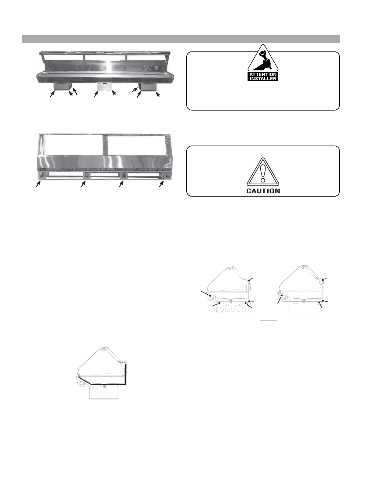
UNCRATING THE STAND
Place the fixture as close to its permanent position as
possible. Remove the top of the crate. Detach the walls
from each other and remove from the skid. Unbolt the
case from the skid. The fixture can now be lifted off the
crate skid. Lift only at base of stand!
NSF7 APPROVED CASES
Cases with the NSF7 are rigidly inspected by our Quality
Control inspectors during construction. The cases are then
temperature and performance tested for 24 hours prior
to shipment.
EXTERIOR LOADING
These models have not been structurally designed to sup-
port excessive external loading. Do not walk on their
tops; This could cause serious personal injury and damage to the fixture.
SETTING AND JOINING
The sectional construction of these models enable them
to be joined in line to give the effect of one continuous
display. A joint trim kit is supplied with each joint.
LIFT-UP GLASS RE-ADJUSTMENT
In addition to verifying that the Allen screws on the lift-up
glass are tightened when the case is delivered, recheck
the Allen screws on the glass ONCE THE CASE IS
IN FULL OPERATION AND BROUGHT TO TEMPERATURE.
Temperature changes can affect the size and shape of the
materials involved, and can cause changes in the secure fit
of the glass and the clamp.
BACK AND SIDE TO SIDE PRIOR TO JOINING. A LEVEL CASE IS NECESSARY TO INSURE PROPER OPERATION, WATER
DRAINAGE, GLASS ALIGNMENT, AND OPERATION OF THE HINGES SUPPORTING
THE GLASS. LEVELING THE CASE CORRECTLY WILL SOLVE MOST HINGE OPERATION PROBLEMS.
NOTE: A. To avoid removing concrete flooring, begin lineup
leveling from the highest point of the store floor.
B. When wedges are involved in a lineup, set them first.
All cases were leveled and joined prior to shipment to
insure the closest possible fit when cases are joined in the
field. When joining, use a carpenters level and shim legs
accordingly.
where support is best, to prevent damage to case.
1. Using case blueprints, measure off and mark on the
floor the exact dimensions of where the cases will
sit. Snap chalk line for front and back positions of
base rail or pedestal. Mark the location of each joint
front and back. Find the highest point throughout
the lineup. FLOORS ARE NORMALLY NOT LEVEL!
Determine the highest point of the floor; cases will
be set off this point. All cases in the entire lineup
must be brought up to the highest level of the case
sitting at the highest point in the lineup. This may be
done a few different ways. 1) Walk the floor looking
for any mounds or dips. 2) Use a string level. 3) Use a
transit. Mark the difference and place the appropriate number of shims required to maintain high-point
level. If a wedge is used in the middle of a lineup, the
wedge must be set of the highest point on the floor
FIRST, with the rest if the lineup being leveled from
it.
NOTE; Pedestals must be shimmed individually
under each corner of the pedestal.
Case must be raised correctly, under legs
LEVELING
IMPORTANT! IT IS IMPERATIVE THAT
CASES BE LEVELED FROM FRONT TO
5
Installation cont’d
Shim standard cases in the middle, and at all other
points under the case along the rail as needed
(depending on case length).
IGSV-ESC-0303
It is the contractor’s responsibility to install
case(s) according to local construction and
health codes.
6. Slide second case up to first case snugly. Then level
second case to the first case so glass front, bumper
and top are flush.
Shimming the cases helps avoid case sag and poor
glass alignment.
2. Set first case, and adjust legs over the highest part of
the floor so that case is level. Prevent damage – case
must be raised under leg or by use of 2x6 or 2x4 leg
brace. Remove side and back leg braces after case is
set.
3. Set second case as close as possible to the first case,
and level case to the first using the instructions in
step one.
4. Apply masking tape 1/8" in from end of case on
inside and outside rear mullion on both cases to be
joined.
5. Apply liberal bead of case joint sealant (butyl) to first
case. Sealant area is shown using a dotted line in
illustration in Step 8. Apply heavy amount to cover
entire shaded area.
DO NOT USE PERMAGUM!
Do not use cam locks to pull cases together.
7. To compress butyl at joint, use two Jurgenson wood
clamps. Make sure case is level from front to back
and side to side on inside bulkheads at joint.
8. Attach sections together via the camlocks pictured
in the illustration below.
A,B
B
A,C,D,E
A,C,D,E
D
Optional St. Steel
Slanted Deck Pan
(Meat/Fish)
A,B,D
A,B,D
A,C,D,E
C,E
LEGEND
A = Straight Case
B = Inside Wedges
°
Wedges
C = 45
D = 30
°
Outside Wedges
°
Outside Wedges
E = 90
9. Apply bead of butyl to top of bulkheads and slip on
stainless steel bulkhead cap. Also apply butyl to
seam between overhead light tubes.
10. VERY IMPORTANT! Apply liberal amounts of
black butyl to area under interior lower legs and fill
all voids down to bulkhead.
11.Use finger to smooth butyl as thin as possible at
masking tape on inside and outside of rear mullion
6
Rev. 0303
Installation cont’d
(apply additional butyl if necessary). Remove tape
applied on line #3.
INSIDE REFRIGERATED WEDGES
Line up taper pins with holes on adjoining case. Turn camlock to lock in. Two camlocks are located at the rear of
the case behind the air discharge and behind the lower
electrical raceway access panel. Bolt the wedge into the
adjoining case in the front. If the adjoining case is refrigerated, the bolt is located under the pans in the front. When
the adjoining case is a hot case, the cases are bolted together by mans of a bracket located behind the front panel.
Remove the front panel by lifting it up and out.
COMMON END BETWEEN UNLIKE CASES AND HOT
CASES
Bolt the end onto the case using the bolts provided in
predrilled holes behind the front of the panel through the
bracket provided and in the rear behind the rear access
panel on the bottom Common ends between refrigerated
cases are also bolted together behind the air discharge
panel. Remove the discharge panel by lifting up and out.
Hot case are only bolted in two places. IN the rear of the
case, behind the access panel and in the front of the case
behind the front panel.
OUTSIDE REFRIGERATED WEDGE:
Ta per pin and camlock locations are the same as a standard case.
INSIDE DRY WEDGES
Bolt the wedge into the sides of the adjoining case. Use
the bolts provided
INSIDE PEDESTAL WEDGES
Set the wedge on adjoining case’s mounting brackets located at the base of the unit, and bolt down. Drive screws
provided through the sides of the wedge (4 screws per
side), accessible through the back of the wedge.
1. Secure the joint backer located behind the cart
bumper support at the joints. To adjust the front
panel. Loosen the screws holding the bumper on the
case on either side the joint, and slide the extrusion
to the center of the joint.
2. Starting from a center case in a lineup or a wedge,
align front panels. Front panels can be loosened and
adjusted laterally by loosening the screws holding
the case bumper channel
**NOTE: Be sure to read the “Important Information” Section
for proper case operation, before loading the merchandiser.
LIFT-UP GLASS RE-ADJUSTMENT
In addition to verifying that the Allen screws on the lift-up
glass are tightened when the case is delivered, recheck
the Allen screws on the glass ONCE THE CASE IS
IN FULL OPERATION AND BROUGHT TO TEMPERATURE.
Temperature changes can affect the size and shape of the
materials involved, and cas cause changes in the secure fit
of the glass and the clamp.
ARM STRUT
GUSSET
WEDGE BRACKET
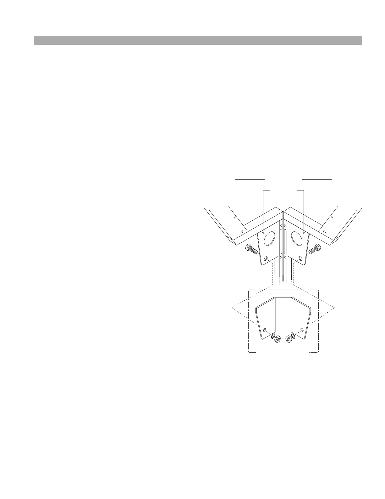
Corner wedges are attached via front and rear camlocks.
Use a 7mm allen wrench to turn the locks. Do not overtighten! Join the top by using a joint bracket (included in
joint kit) with 3/8" bolts.
7

ESC Glass Adjustment
NOTE: Before making any of the recommended adjustments,
Verify that the case(s) have been leveled properly.
IGSV-ESC-0303
Glass Adjustment
Tech/glassadj/970602 tn
Adjust glass Up and Down
(vertically)
A
Adjust glass Front to Back
B
Adjust glass Side to Side
(horizontally)
C
1. Remove 2. Remove 3. Loosen front 4. Turn height adjustment screw 5. Check alignment
rear prep galvanized locking screw to raise and lower mullion. and retighten
ledge. sub top. ONLY! (1/8" set screw) front locking
1. Remove 2. Loosen front 3. Loosen back 4. Back out 5. Slide the mullion arm
rear prep locking screw locking screw height adjustment forward or backward
ledge and FIRST! SECOND! screw, until arm by moving the mullion
remove (5/16" flat head). (5/16" flat head). bottoms out on structure itself.
galvanized the gusset bracket Max travel = 5/8"
sub top COUNT # of turns!
(see above). (1/8" set screw).
6. Restore the height adjustment screw
to original position (from step 4)
and verify glass alignment.
Retighten
from step 1.
1. Open glass 2. Back out 3. Slide glass
panel. all the set screws in desired direction.
Relieve the along the top
tension on edge of the glass
the hinge. panel to open clamp.
rear then front lockings screws
(3mm set screw)
(5/16"x1.25" Max travel = 1/4" screw and re Flat head). CW – mullion up, install removed
Back
of Case
CCW – mullion dwn. components.
Mullion
Structure
(Case arm)
Inside
of Case
IMPORTANT
PVC
U-channel
CUT VIEW:
rear ledge
and glass
adjustment
screws
LIFT-UP GLASS RE-ADJUSTMENT
In addition to verifying that the Allen screws on the lift-up glass are tightened when the case is delivered, recheck the Allen
screws on the glass ONCE THE CASE IS IN FULL OPERATION AND BROUGHT TO TEMPERATURE.
Te mperature changes can affect the size and shape of the materials involved, and can cause changes in the secure fit of the
Technical Support: 800-395-9229
®
/CHINO
glass and the clamp.
8

Rev. 0303
Plumbing
WASTE OUTLET AND P-TRAP
The waste outlet is located off the center of the case on
one side allowing drip piping to be run lengthwise under
the fixture.
A 1-1/2" P-trap and threaded adapter are supplied with
each fixture. The P-trap must be installed to prevent air
leakage and insect entrance into the fixture.
NOTE: PVC-DWV solvent cement is recommended.
Follow the manufacturer’s instructions.
INSTALLING CONDENSATE DRAIN
Poorly or improperly installed condensate drains can seriously interfere with the operation of this refrigerator,
and result in costly maintenance and product losses. Please
follow the recommendations listed below when installing
condensate drains to insure a proper installation:
1. Never use pipe for condensate drains smaller than
the nominal diameter of the pipe or P-trap supplied
with the case.
2. When connecting condensate drains, the P-trap
must be used as part of the condensate drain to
prevent air leakage or insect entrance. Store plumbing system floor drains should be at least 14" off the
center of the case to allow use of the P-trap pipe
section. Never use two water seals in series in any
one line. Double P-traps in series will cause a lock
and prevent draining.
3. Always provide as much down hill slope (“fall”) as
possible; 1/8" per foot is the preferred minimum.
PVC pipe, when used, must be supported to maintain the 1/8" pitch and to prevent warping.
4. Avoid long runs of condensate drains. Long runs
make it impossible to provide the “fall” necessary for
good drainage.
5. Provide a suitable air break between the flood rim of
the floor drain and outlet of condensate drain. 1" is
ideal.
6. Prevent condensate drains from freezing:
a. Do not install condensate drains in contact with
non-insulated suction lines. Suction lines should be
insulated with a nonabsorbent insulation material
such as Armstrong’s Armaflex.
b. Where condensate drains are located in dead air
spaces (between refrigerators or between a
refrigerator and a wall), provide means to prevent
freezing. The water seal should be insulated to
prevent condensation.
Manifold Flush System
GENERAL DESCRIPTION
Tw ice a day for two (2) minutes, a high pressure water
stream will flush most residue build-up from the bottom
of the manifold chamber. This is the area that residue builds
and expands from. Frequency of this periodic maintenance
will vary depending on water mineral content and sanitary conditions.
AUTOMATIC FLUSH SYSTEM
Electrical components are located within the electrical
raceway. Electrical components in this area are 115V AC.
Water flow for flush system is rated at 0.25 GPM at 60PSI
water pressure. Flush nozzles are located in the front of
the case.
BASIC SYSTEM OPERATION:
1. Filtered water is supplied to the 115V solenoid valve.
2. At a time of day determined by you, the 115V time
clock will energize the solenoid for 2 minutes.
START UP:
1. Manually move time clock to initiate a flush cycle.
2. Observe that flush nozzle is spraying down center of
manifold chamber.
3. Set clock to correct time of day.
4. Set trip pins to the “time of day system is to flush”
(NOTE: 2 flush/day!)
MANUAL FLUSH SYSTEM
Water valve is located on the outside of the case, in the
rear, on the left hand side as viewed from the rear.
BASIC SYSTEM OPERATION:
1. Open the water valve to allow the flush system start.
It is recommended that the case is flushed two (2) times
daily for two (2) minutes.
MAINTENANCE:
Perform maintenance when servicing humidity system.
9

Humidity System
IGSV-ESC-0303
GENERAL DESCRIPTION
One contributor to the spoilage of fresh meats is dehydration, which causes loss in weight and volume (shrinkage) and product discoloration. As the refrigeration system removes heat from the case, it also removes critical
moisture from the air, and any unwrapped products in
the case. The Humidity System replaces the moisture in
the air, in order to compensate for the moisture taken
by the refrigeration system, and disposed of down the
drain line. The system is built into the discharge plenum,
and mixes moisture laden air with refrigerated air before the air is passed through - and around the product.
The system is constructed almost entirely of PVC pipe,
and uses air that is subcooled to approximately the same
temperature as the case. The sub-cooling of air inhibits
the formation of growth found to be a problem in other
humidification systems. Maintenance is almost unnecessary if you follow a few simple rules:
1. Keep the case clean.
2. Keep the water filter clean, and change it every 6-12
months or sooner, depending on the kind of water found
in your area.
3. Flush the header every 6 months, by loosening the
connecting “L”, then removing it from the case, and flushing with a hose.
**IMPORTANT INFORMATION**
The ESC is capable of maintaining superb product quality with the installation of the proper controlling devices. These devices should be set according to the
manufacturer’s specifications. The humidity system should
be properly maintained. Incorrect settings and failure to
maintain the humidity system will result in short product life. Below are a few guidelines for optimum performance and product life:
• Set thermostat to cut in at the discharge temperature designated in the case specifications section
of the appropriate installation guide or spec. sheet.
Maintain the recommended product temperature
for Deli, Meat, and Fish. DO NOT set temperature
too cold, as this causes product dehydration.
•Temperatures should be achieved by means of a TStat and Suction Solenoid at each case. DO NOT
use EPR valves, Liquid Line Solenoids, or electronic
control devices of any kind. These controls allow
temperature swings that cause dehydration and
excessive energy consumption.
• Set defrost cycles as listed in the Case Specifications Data for your particular case. The number of
defrosts per day should never change. The duration of the defrost cycle may be adjusted to meet
conditions present at your location.
•Clean humidity system a minimum of every 90 days
for proper system operation.
•Work and rotate product - not to exceed a 4-hour
period.
•At night, turn off case lights, and cover unwrapped
product with moistened cheesecloth or fabric
towels.
•Keep meat holding box at 32°F
•Keep meat prep room refrigerated at 55°F
• Meat Bloom Box (if applicable) should be at 36°F
• Meat must enter the case at 40°F or below. Product
deteriorates rapidly above 40°F.
•Clean sanitary conditions throughout the meat
holding, prep, and work areas.
• Do not display product directly within the air
discharge
•Turn and rotate meat. The blood works down
through the meat over time, which causes the top
surface to discolor and dehydrate. Turn meat 3-4
times.
• It is not required to remove product from case
overnight. Turn off case lights, and cover product
with moistened cheesecloth or fabric towel. This
helps slow down product dehydration, by taking
moisture from the cloth and not the product. This is
an old method used by meat shops for many years,
as it extends product life.
• Cold coils remove heat & moisture from the case
and deposit this as frost onto the coil. Thus a defrost
is required to remove this frost. Our humidity
system induces moisture into the case, and helps
slow down the dehydration process. The only other
moisture in the case is that which is in the product. A
single level of meat will dry out faster than a fully
loaded case with 3-4 levels of meat.
• The colder the case, the faster the product loses its
moisture and shelf life. It is very important to
maintain a constant, even, correct, product temperature.
10
Rev. 0303
Humidity System, cont’d
HUMIDIFICATION SYSTEM HOOKUPS
Remove the raceway panel on the lower back of the case.
The pre-piped water shut-off valve and the water filter
are located on the left hand side of the case. The water
line (which is a 1/4" OD copper fitting) can be connected
to the ball shut-off valve, by means of a compression fitting (supplied). The line should be one size larger than the
supply line. The line can then be run from one case to
another from within the raceway(s) using Tee connectors.
Before connecting the water to the humidity system, it is
best to purge the line to flush any debris that may clog the
water filter. If the water line requires purging after the
cases are hooked together, it is not necessary to check
each one. Simply shut ball valves to each humidity system,
remove the water line from the last case in the flow, and
purge. By doing this as a precautionary measure, you may
avoid problems and repeat servicing.
START-UP
Turn on the fan circuit. Check to see if the fan for the
humidity system is running. Remove the right hand bottom pan (when facing the front of the case), then the TXV
cover. The fan is located up against the right hand side of
for proper system operation.
SPRAY HEADER
RUNS LENGTH
OF CASE
SCOTTDALE NOZZLE
225-01-2089A
the case, as viewed from the front, under the fan plenum
(see diagram). View the blade, and make sure the fan rotation agrees with the air flow arrows. Turn on the water, by
turning the ball valve in the direction of the flow (OFF is
at 90° to the direction of flow).
After a few minutes, Check the spray header by removing
the discharge air grill located on the right hand side of the
case (when viewed from the rear), by lifting the 4'-0" section of grill by both ends, until the bottom clears. Pull up
and set aside. The spray header will be exposed. Grasp the
header and pull it loose from the 90° “L” until you see the
misting nozzle, which should be spraying. If not, check the
following:
1. Make sure the water is feeding the nozzle
2. Remove the nozzle, and purge the water
3. Check strainer at entrance to nozzle
Reinsert the header into the 90° “L”, making sure that the
nozzle is in the center of the pipe when totally inserted,
and the holes in the header are facing the front of the case
at a level angle.
MAINTENANCE
•Clean humidity system a minimum of every 90 days
1/4" 100 X 1/8FPT
SW ADAPTER
REAR INTERIOR WALL OF CASE
VIEWED FROM FRONT
1/4"MPT X 1/4" COMP
PVC ADAPTER
225-01-2026
WATER
SUPPLY
1/4"MPT X 1/4" OD
COMP ADAPTER
225-01-1312
BALL VALVE
HAMMON
225-01-2026
WATER FILTER
3 STAGE #00015
225-01-3047
2ND FAN USED
IN 12' CASE
HUMIDITY SYSTEM as viewed from the front.
Note: The axial fans included in the humidity system must be replaced as a unit.
1/4" OD X 1/8" FPT
SW ADAPTER
225-01-3059
1/8" MPT X 1/4" COMP
PVC ADAPTER
225-01-3059
PAN AND
ACCESS PANEL
3" AXIAL FAN
225-01-2026
11
Refrigeration
REFRIGERANT TYPE
The standard refrigerant will be R-22 unless otherwise
specified on the customer order. Check the serial plate
on the case for information.
PIPING
The refrigerant line outlets are located under the case.
Locate first the electrical box, the outlets are then on the
same side of the case but at the opposite end. Insulate
suction lines to prevent condensation drippage.
REFRIGERATION LINES
LIQUID SUCTION
3/8" O.D. 5/8" O.D.
NOTE: The standard coil is piped at 5/8" (suction); however,
the store tie-in may vary depending on the number of
coils and the draw the case has. Depending on the case
setup, the connecting point in the store may be
5
/8", 7/8", or 11/8". Refer to the particular case you are
hooking up.
Refrigerant lines should be sized as shown on the refrigeration legend furnished by the store.
Install P-traps (oil traps) at the base of all suction line vertical risers.
Pressure drop can rob the system of capacity. To keep the
pressure drop to a minimum, keep refrigerant line run as
short as possible, using the minimum number of elbows.
Where elbows are required, use long radius elbows only.
CONTROL SETTINGS
See the “Case Specs” section of this guidebook for the
appropriate settings for your merchandiser. Maintain these
parameters to achieve near constant product temperatures. Product temperature should be measured first thing
in the morning, after having been refrigerated overnight.
For all multiplexing, defrost should be time terminated.
Loadmaster valves are not recommended. Defrost times
should as directed in the Case Specifications section of
this guide. The number of defrosts per day should never
change. The duration of the defrost cycle may be adjusted
to meet conditions present at your location.
ACCESS TO TX VALVES & DRAIN LINES
MECHANICAL - Remove product from end of case. Remove
product racks. Remove refrigeration and drain access panels
(labeled). TX valve (mechanical only) and drain are located
under each access panel at end of the case.
ELECTRONIC - The Electronic Expansion valve master and
slave cylinder(s) are located within the electrical access
panel(s).
ELECTRONIC EXPANSION VALVE (OPTIONAL)
A wide variety of electronic expansion valves and case
controllers can be utilized. Please refer to EEV and controller manufacturers information sheet. Sensors for elec-
IGSV-ESC-0303
tronic expansion valves will be installed on the coil inlet,
coil outlet, and in the discharge air. (Some supermarkets
require a 4th sensor in the return air). Case controllers
will be located in the electrical raceway or under the case
THERMOSTATIC EXPANSION VALVE LOCATION
This device is located on the same side as the refrigeration stub. A Sporlan balanced port expansion valve model
is furnished as standard equipment, unless otherwise specified by customer.
EXPANSION VALVE ADJUSTMENT
Expansion valves must be adjusted to fully feed the evaporator. Before attempting any adjustments, make sure the
evaporator is either clear or very lightly covered with frost,
and that the fixture is within 10°F of its expected operating temperature.
MEASURING THE OPERATING SUPERHEAT
1. Determine the suction pressure with an accurate
pressure gauge at the evaporator outlet.
2. From a refrigerant pressure temperature chart,
determine the saturation temperature at the
observed suction pressure.
3. Measure the temperature of the suction gas at the
thermostatic remote bulb location.
4. Subtract the saturation temperature obtained in step
No. 2 from the temperature measured in step No. 3.
3. The difference is superheat.
5. Set the superheat for 5°F - 7°F.
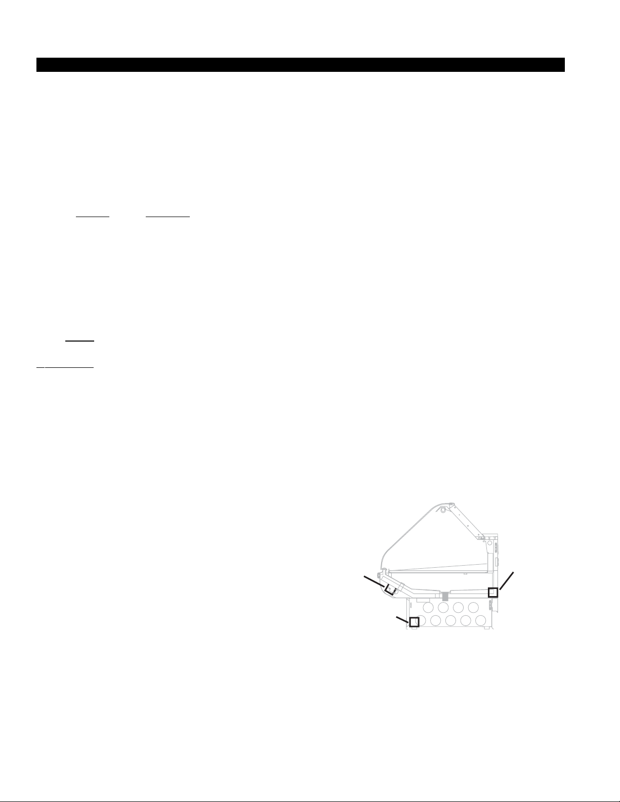
T-STAT LOCATION
T- Stats are located within the electrical raceway. Refer to
diagram below.
Standard
Location
Optional
Location
Optional
Location
12
 Loading...