

Page 1
January 2006
INSTALLATION & SERVICE
INSTRUCTIONS
FOR
DDS – DDSS SELF-CONTAINED AND REMOTE
Multi-deck, Spot display
Refrigerator Merchandisers
First Call for help (US and Canada):
1-800-922-1919
Soporte Tècnico y Asistencia (Mèxico):
01-800-522-1900
For a Service Network Locator and other
Information visit us at
www.hussmann.com
select Worldwide Locations
HUSSMANN - GLOVERSVILLE
P/N OII – DDS, DDSS Merchand isers
January 2006
Page 2

TABLE OF CONTENTS
SECTION 1 General Information Page 3
SECTION 2 Installation Page 4
SECTION 3 Refrigeration Page 5
Self Contained Models
SECTION 4 Refrigeration Page 6
Remote Models
SECTION 5 Electrical Page 12
SECTION 6 Replacement Parts List Page 14
SECTION 7 User Instructions Page 20
SECTION 8 Service Tips and Wiring Diagrams Page 22
Page 3
SECTION 1
GENERAL INFORMATION
MODEL DESCRIPTION
The DDS model seri es are multi-deck, spot merchandisers designed for medium tem pe ratu re
area of the case ready for operation wh en electrical service is connec ted.
requi rements for the rem ote model will be 120 v olt, 60 hertz (Hz).
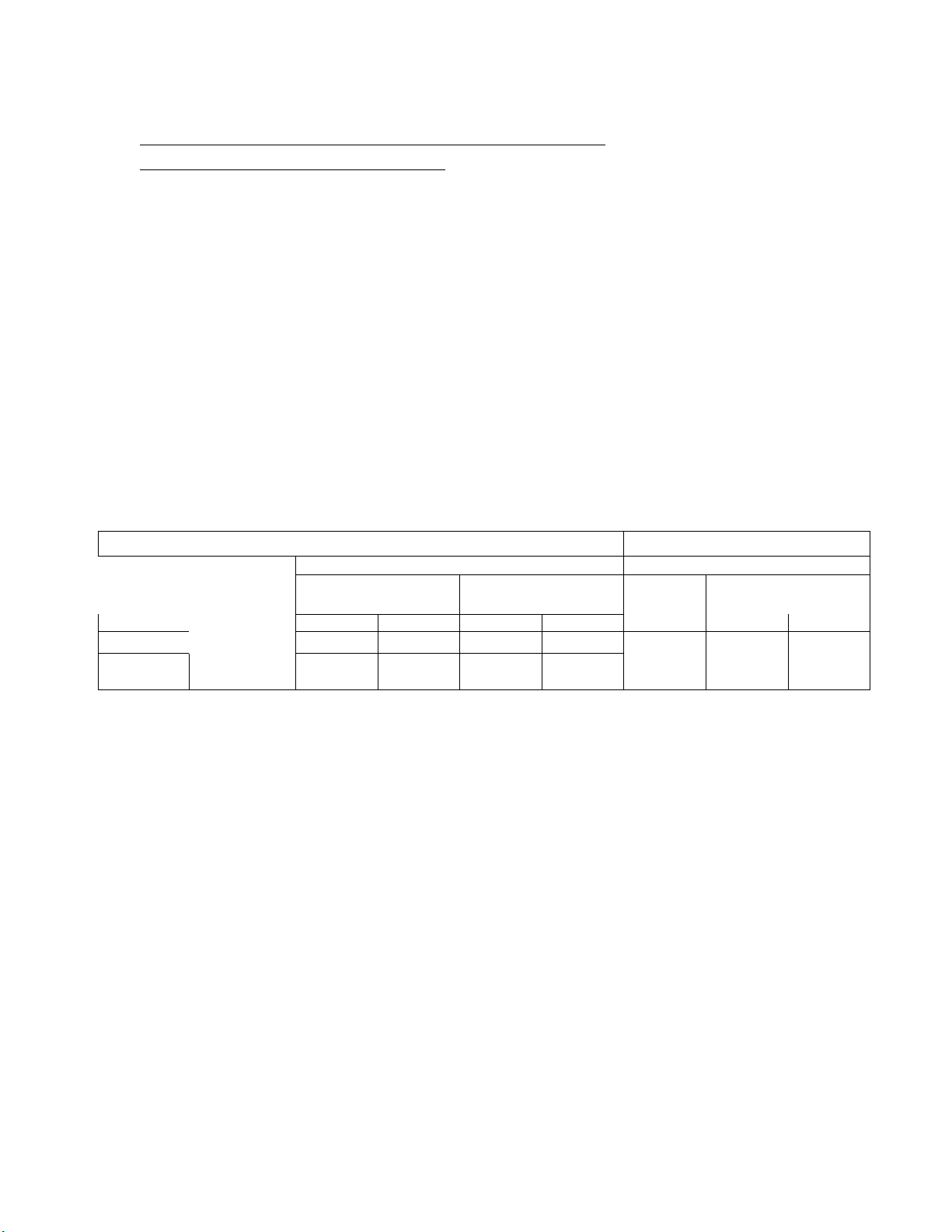
MODEL ELECTRICAL DESCRIPTION
MODEL
DESCRIPTION
ELECTRICAL SERVICE
Symbol
∅
den otes
APPLICATION
less and relative hu midity does not exceed 55%.
HUSSMANN - GLOVERSVILLE
applica ti ons such as : deli/dairy/bevera ge /floral. They are avail ab l e as eithe r remote ty pe
models, which requi re sepa rate condensing unit connections, or self -con tain ed m odels. Each
self -c ontai n ed model will have i t’s own c on de nsing unit, fac tory installed ben ea th the di s pl ay
The f ollowing table lists the standa rd models wi th a brief description of each, incl uding the
elec trical requi rem en ts of the self-con tained m odel. Unless otherwis e specifi ed , the elec trical
DDS/DDF-4B Self-Contained 4’ Merchandiser 115 / 60 Hz / 1
DDS/DDF-4D/G Self-Contained 4’ Merchandiser 230v - 208v / 60 Hz / 1
DDS/DDF-6D/G Self-Contained 6’ Merchandiser 230v - 208v / 60 Hz / 1
DDS/DDF-8D/G Self-Contained 8’ Merchandiser 230v - 208v / 60 Hz / 1
DDS/DDF-4R Remote Type 4’ Merchandiser 115 / 60 Hz / 1
DDS/DDF-6R Remote Type 4’ Merchandiser 115 / 60 Hz / 1
DDS/DDF-8R Remote Type 4’ Merchandiser 115 / 60 Hz / 1
DDSS-4D/G Self-Contained 4’ Merchandiser 230v- 208v / 60 Hz / 1
∅
∅
∅
∅
∅
∅
∅
∅
These models are designe d for use only in air-conditioned stores where temperature is 75°F or
Page 4

03 Page 4
SECTION 2
INSTALLATION
SHIPPING DAMAGE
All equipment should be examined for shipping damage before and during unloading. If there is
any damage, the carrier should be notified immediately and an inspection requested. The
delivery receipt must be noted that equipment was received damaged. If damage is of a
concealed nature, we suggest the carrier be contacted immediately, or no later than (3) days
following delivery. The consignee for all damages must file a claim with the carrier.
SHIPPING BRACES
Move the fixture as close as possible to its permanent location then remove all packaging and
shipping braces. Remove all separately packed accessories such as kits, shelves, etc.
EXTERIOR LOADING
These cases are not structurally designed to support excessive external loading such as the
weight of a person, therefore, do not walk on the top of these refrigerators or damage to the
refrigerator and serious personal injury could occur.
LOCATION
These refrigerators, like other open refrigerators, are sensitive to air disturbances. Air currents
passing around them will seriously impair their operation. Do not allow air-conditioning,
electric fans, open doors or windows, etc. to create air currents around these cases.
DO NOT INSTALL THE VENTED PANELS OF THE SELF-CONTAINED MODELS
AGAINST A WALL OR OTHER STORE FIXTURE.
Located in the lower front and rear of the self-contained models are vented panels. These panels
allow air circulation to the condensing unit. Blocking or restricting air circulation through these
panels can cause poor performance and damage the refrigeration system.
INSTALL THE REFRIGERATOR NO CLOSER THAN (4) FOUR INCHES FROM A WALL OR OTHER
STORE FIXTURES.
HUSSMANN - GLOVERSVILLE
Page 5
07/02/03
Page 5
SECTION
3
REFRIGERATION
-
SELF CONTAINED MODELS
Each self-contained model is eq uipped with its own condensing unit located ben eath the display
serv ice valves open, compl e tel y ready for operation when elec trical power h as been connected.
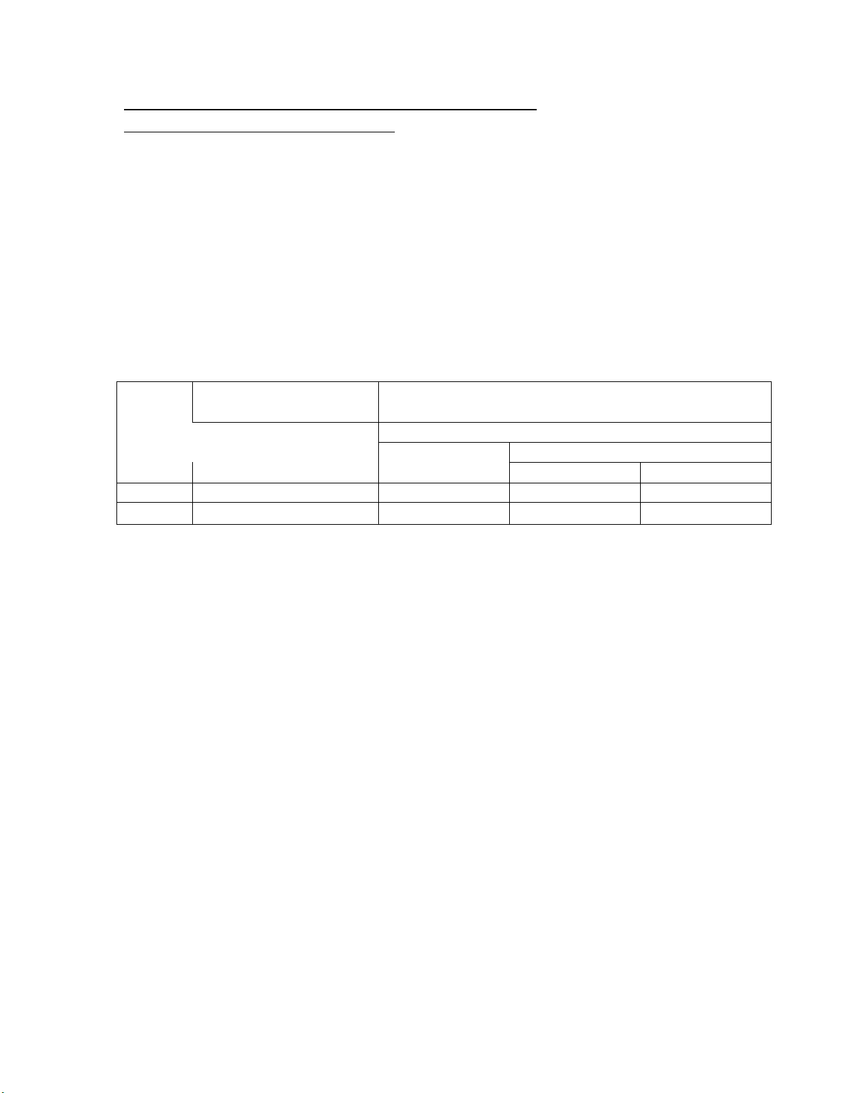
REFRIGERANT
CHARGE
DDS/DDF-8D /G
R – 404A
8
2
DDS – 4D/G c/w
Hp
Condens in g
Unit
R - 22
50DDSS – 4D/G
R-22
5
8
CONTROLS a nd ADJUSTMENTS
TEMPERATURE
FREQUENCY
FAILSAFE
28° to 34
°
F
Every
6 Hours
90 psig (R-22)
105 psi g (R-404A)
45
Minutes
honeycomb.
s
k
HUSSMANN - GLOVERSVILLE
area. The unit will be charged per nameplate refri ge rant and shipped from the fa ctory with all
MODEL REFRIGERANT POUNDS OUNCES
DDS/DDF -4B R - 22 5 8
DDS/DDF-4D /G R - 22 5 8
DDS/DDF-6D /G R - 22 7 11
REFRIGERATION
CONTROLS
DISCHARGE AIR
A ref rigeration thermostat con trol s refrige ration tempera ture . The control i s f actory
installed in th e c ontrol p anel. Adjust this thermostat to m aintai n th e discharge air
temperature sh own . Meas ure dis ch arg e air temperatures at the center of the discharge
Defrosts are time-initiated and pressure terminated. The defrost timer is factory set a
shown. Check that the above settings are imp lemented and correct, and that the cloc
indicated the correc t tim e of day.
Defrost m ust be terminated by def rost termi nation settin g.
DEFROST
DEFROST CONTROLS
PRESSURE
TERMINATION
Page 6

07/02/03 Page 6
SECTION 4
REFRIGERATION - REMOTE MODELS
REFRIGERANT PIPING
Refrigerant line connection sizes: All models LIQUID LINE 3/8” OD
SUCTION LINE 5/8” OD for 4’ & 6’ Models; 1 1/8” for all other models
These connections are made at the right hand end of the cases (facing front) beneath the
refrigerated display area. Refrigerant lines should be sized as shown on the refrigeration legend
(furnished by the owner). If a legend has not been furnished, refer to Section 12 of the
Hussmann Application Engineering Manual for guidance.
OUTLET LOCATION
The refrigerant line outlet is located at the right hand end of the refrigerator beneath the display
pans. After connections have been made, seal this outlet thoroughly both on the inside and the
outside. An aerosol dispensed urethane type of insulation is recommended.
LINE SIZING
Refrigerant lines should be sized as shown on the refrigeration legend prepared for the store and
as (furnished by the owner). If a legend has not been furnished, refer to Section 12 of the
Hussmann Application Engineering Manual for guidance.
OIL TRAPS
P-traps (oil traps) must be installed at the base of all suction line vertical risers.
PRESSURE DROP
Pressure drop reduces capacity of the refrigeration system. To minimize pressure drop, use
proper size tubing, keep the refrigerant line runs as short as possible and use a minimum number
of elbows. Where elbows are needed, use long radius elbows only.
PIPING INSULATION
For refrigerators with other than KOOLGAS defrost, the suction and liquid lines should be
clamped and/or taped together and insulated for a minimum of 30 feet from the refrigerator.
Refrigerators with KOOLGAS defrost should not have their liquid and suction lines in contact
with each other but are to be separately insulated for a minimum of 30 feet from the refrigerator.
Additional insulation for the balance of the refrigerant lines is recommended and required
wherever condensation and dripping would be objectionable.
HUSSMANN - GLOVERSVILLE
Page 7

07/02/03 Page 7
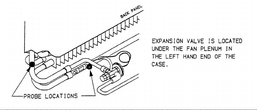
EXPANSION VALVE ADJUSTMENT
Expansion valves must be adjusted to fully feed the evaporator. Before attempting to adjust
valves, make sure the evaporator is either clear of / or only lightly covered with frost, and that
the fixture is within 10° F of it’s expected operating temperature.
Adjust the valve as follows:
A. Attach a probe to the suction line near the expansion valve bulb.
B. Obtain a pressure reading from the factory installed Schraeder valve. Convert
the pressure reading to a saturated temperature for the appropriate refrigerant
Temperature B minus Temperature A = Superheat
Some “hunting” of the expansion valve is normal. The valve should be adjusted so that during
the hunting the greatest difference between the two temperatures is 3° F to 5° F.
With this adjustment, during a portion of the hunting the temperature difference between the
probes will be less than 3° F (at times as low as 0° F).
Make adjustments of no more than (1/2) turn of the valve stem at a time and wait for at
least fifteen minutes before rechecking the probe temperature and making further
adjustments.
Page 8
Page 9
07/02/03 Page 8
REFRIGERATION & DEFROST CONTROLS FOR
CONVENTIONAL OPERATION
(Single Compressor System)
Refrigeration temperature may be controlled by either the condensing unit’s low-pressure
control or by refrigeration thermostat (optional / one per condensing unit). Thermostatic control
is preferred since it will provide a more constant year-round control of temperature. The
thermostat may be field or factory installed, must have a differential of 3° F to 6° F and have its
sensing bulb located to monitor the air leaving the evaporator. One thermostat per condensing
unit is required and should be wired into the compressor motor contactor control circuit.
A pump down system is recommended for outdoor condensing units.
DEFROST:
DDS models have defrost cycles that are time initiated and time terminated.
REFRIGERATION CONTROLS
Discharge
Air
Temp
(Cut-out)
28°F
c
c
Convert
Temperatures
to Pressures for
type of
Refrigerant
Used
LOW PRESSURE CONTROL SETTINGS DEFROST TIMER
If used to control
temperature
d
(Cut-out) (Cut-in)
If thermostat controls
temperature
e
(Cut-out) (Cut-in)
12°F 30°F -7°F 26°F
Measure discharge air temperatures at the center of the honeycomb. If thermostat is
DEFROST CONTROLSf
Defrost
Frequency
Every
6 Hours
used to control temperature, set thermostat to open contacts at the discharge air
d
temperature given in the table.
Adjust the cutout on the low-pressure control to stop the compressor at the discharge
temperature given in the table. Final adjustment should be made after refrigerator is
stocked with product. If cycle frequency is more than 4 times per hour, cycling should
produce an average discharge air temperature as shown above.
e
These settings are acceptable for outdoor unit applications when the coldest expected
ambient does not go below 0° F. If colder ambient temperatures are expected, set
control accordingly per “Hussmann Condensing Unit Installation Instructions.
f
If these spot display refrigerators are to be multiplexed with a different type refrigerator,
compare these defrost settings with those specified for the other refrigerator. If the
settings are not compatible, refer to page 15 (Controls & adjustments – Mixed
Multiplexing).
Failsafe
Length
Termination
Pressure
45 Min 90 psig
HUSSMANN - GLOVERSVILLE
Page 10
07/02/03 Page 9
REFRIGERATION & DEFROST CONTROLS FOR
CONVENTIONAL OPERATION - Mixed Multiplexing (Parallel Racks)
Refrigeration temperature may be controlled by a refrigeration thermostat sensing discharge air
temperature. The thermostat controls a liquid line solenoid (optional) or a suction line solenoid
(optional). The use of an evaporator pressure regulator (EPR) is recommended to allow fixture
to refrigerate at steady levels.
DEFROST:
DDS models have defrost cycles that are time initiated and time terminated.
MODEL
ALL
c
d
e
f
Each system shown on the “store legend” must have staggered defrosts to maintain stable
compressor loading and a sufficient supply of defrost gas.
Discharge air temperature is to be measured by attaching a service thermometer to the
discharge honeycomb at the centre of the case.
Adjust the refrigeration thermostat or EPR valve to maintain the discharge air
temperature shown above.
If these spot display refrigerators are to be multiplexed with a different type refrigerator,
compare these defrost settings with those specified for the other refrigerator. If these
settings are not compatible, refer to the following page.
KOOLGAS defrost is time initiated and time terminated. The defrost lengths listed
above are based upon laboratory testing but operation under actual store conditions may
require that they be lengthened to accomplish a thorough defrost. Some of the store
conditions that can contribute to a longer defrost are: low head pressure, long runs of
refrigerant lines, store ambient, fixture temperature operating lower than that
recommended, seasonal ambient changes etc.
REFRIGERATION
CONTROLS
DISCHARGE
AIR TEMP c
(Cut-out)
28° F
DEFROST CONTROLS d
DEFROST
Frequency
Every 6 Hours
DEFROST TIMER
Length of Defrost
Off-Time/Electric
45 Min e
14 Min
KOOLGAS
f
HUSSMANN - GLOVERSVILLE
Page 11

07/02/03 Page 10
REMOTE CONTROL KIT (Optional)
The control settings listed in the preceding tables are those that will provide proper case
performance. If these spot display refrigerators are to be multiplexed with different types of
refrigerator models, we suggest that each spot display refrigerator be equipped with a
“REMOTE CONTROL KIT”.
The remote control kit will insure better control of refrigeration temperature and provide
additional defrost controls that maybe needed since most other refrigerators do not have similar
defrost frequencies and terminations (fail safeguards) with these spot display refrigerators.
The remote-control kit will be factory installed below the display area of the spot display
refrigerator. A liquid line solenoid valve will also be installed.
The liquid line solenoid valve will open when energized. During refrigeration, the valve is
controlled by the refrigeration thermostat (close-on-rise of temperature) providing better and
more specific control of refrigeration temperature. The defrost timer controls the valve for
defrost; closing the valve for initiation; opening the valve at termination.
The remote control kit timer must be synchronized with the timer of the unit.
HUSSMANN - GLOVERSVILLE
Page 12

Page 13

07/02/03 Page 12
SECTION 5
ELECTRICAL
CONNECTIONS
Electrical power connections are made at the left hand end of the case, behind the removable
front or rear base panels.
REMOTE MODELS
All electrical connections for remote models will be made in the junction box located behind the
removable front base panel, at the left hand end of the case.
SELF CONTAINED MODELS
All electrical connections for self-contained models will be made in the control panel of the
case. All electrical connections have been terminated inside the control panel and “pig-tailed”
for ease of connecting field wiring. See appropriate wiring diagram in this section.
CAUTION:
NOTE: ALL WIRING AND CONNECTIONS MUST COMPLY
THE FIXTURE MUST BE ELECTRICALLY GROUNDED.
WITH N.E.C., STATE, PROVINCIAL AND LOCAL CODES.
HUSSMANN - GLOVERSVILLE
Page 14

07/02/03 Page 13
SERIAL PLATE AMPERAGES
Serial plate amperes are the amperage figures that are stamped on the fixture’s Serial Plate.
Although all field installed wiring must be sized to the Serial Plate amperages, the actual current
or amps may be less than specified. DDS Serial Plate is located on the upper left hand corner of
the top interior panel inside the case.
REMOTE MODELS - R
ELECTRICAL SERVICE
DDS / DDF- 4R 115 v / 60 Hz 2.7 1.3
DDS / DDF- 6R 115 v / 60 Hz 6.2 2.6
DDS / DDF- 8R 115 v / 60 Hz 4.7 2.6
CIRCUIT REQUIREMENTS MODEL
LIGHTS
(amps)
FANS
(amps) c
SELF CONTAINED MODELS – B, D/G
ELECTRICAL SERVICE
CIRCUIT REQUIREMENTS MODEL
LIGHTS
(amps)
Condensing Unit,
Evaporator Pan Heater,
(amps) c
Fans
DDS / DDF- 4B 115 v / 60 Hz 2.70 19.0
DDS / DDF- 4D/G
DDS / DDF- 6D/G
DDS / DDF- 8D/G
230 v - 208 v / 60 Hz / 1∅
230 v - 208 v / 60 Hz / 1∅
230 v - 208 v / 60 Hz / 1∅
2.70 10.3
6.2 18.0
5.2 22.65
DDSS-4D/G
115V/208V/230V/1∅/60
0.43 12.01
Hz
DDSS-4D/G
115/208/230V/1∅/60 Hz
0.43 12.01
Fans are to be continuously energized.
c
The amperage figure shown includes the maximum number of
lighted shelves where applicable
HUSSMANN - GLOVERSVILLE
Page 15

07/02/03
Page 14
SECTION 6
REPLACEMENT PARTS LIST: DDS-4B, DDS-4R
ITEM #
HUSSMANN
DESCRIPTION
PART #
1
21-S-138 Fan Motor,
2 21-S-136 Fan Blade
NOTE: Items 1 through 5 are standard parts for both the DDS-4B and DDS-4R
HUSSMANN - GLOVERSVILLE
3 06-S-214 Bulb
4 06-S-187 Ballast –
5 17-s-390 Expansion Valve - R-22
17-S-541 R-404/507
6 04-S-067 Temperature Ctrl
7 03-S-286 Power Switch
8 19-S-757 Condensate Pan Htr. 570W 120V
19-S-766 Co ndensate Pan Htr. 500W 208V
9 02-S-631 Compressor R22 115V
10 17-S-507 Drier
11 03-S-562 Fuse (Elect. Box)
12 14114 Pressure Control
13 03-S-559 Timer 120V 60Hz
03-S-560 208-203V 60Hz
Page 16

07/02/03
Page 15
SECTION 6
REPLACEMENT PARTS LIST: DDS – 4 D/G
ITEM #
HUSSMANN
DESCRIPTION
PART #
1
21-S-138 Fan Motor
HUSSMANN - GLOVERSVILLE
2 21-S-136 Fan Blade
3 06-S-214 Bulb
4 06-S-187 Ballast 5 17-S-390 Expansion Valve – R-22
17-S-541 R-404/507
6 04-S-067 Temperature Ctrl
7 03-S-286 Power Switch
8 03-S-559 Defrost Timer – 120V 60Hz
03-S-560 208-230V 60 Hz
9 17-S-507 Drier
10 14114 Pressure Control
11 03-S-568 Contactor
12 02-S-632 Compressor R22 208-230V
13 19-S-757 Condensat e Pan Htr. 570W 120V
19-S-766 500W 208V
Page 17

07/02/03
Page 16
SECTION 6
REPLACEMENT PARTS LIST: DDS - 6 D/G and DDS - 6R
ITEM #
HUSSMANN
DESCRIPTION
PART #
1
21-S-138 Fan Motor,
2
21-S-136 Fan Blade
Items 6 through 13 are standard parts for only the DDS-6D/G Model
HUSSMANN - GLOVERSVILLE
3 06-S-233 Bulb
4 06-S-187 Ballast
5 17-S-535 Expansion Valve R-22
17S545 R404
17-S-565 R401
6 04-S-067 Temperature Control
7 03-S-286 Power Switch
8 03-S-559 Defrost Timer 120V 60 Hz
03-S-560 208-230V 60Hz
9 19-S-757 Condensate Pan Htr. 570W 120V
19-S-766 500W 208V
10 17-S-507 Drier 11 03-S-562 Fuse – Electrical Box
12 03-S-568 Contactor
13 02-S-633 Compressor R22 208/230V
NOTE: Items 1 through 5 are standard parts for both the DDS-6D/G and DDS-6R
Models
Page 18

07/02/03
Page 17
SECTION 6
REPLACEMENT PARTS LIST: DDS - 8 D/G and DDS - 8R
ITEM #
HUSSMANN
DESCRIPTION
PART #
1
21-S-138 Fan Motor
HUSSMANN - GLOVERSVILLE
2 21-S-136 Fan Blade
3 06-S-214 Bulb
4 06-S-187 Ballast
5 17-S-545 Expansion Valve R404
6 04-S-067 Temperature Control
7 03-S-286 Power Switch
8 03-S-560 Defrost Timer 208-240V 60 Hz
9 19-S-757 Condensate Pan Htr. 570W 120V
19-S-766 Condensate Pan Htr 500W 208V
10 17-S-507 Drier 11 03-S-563 Fuse Electrical Box
12 03-S-298 Contactor
13 02-S-638 Compressor R404 208/230V
Page 19

07/02/03 Page 18 18
SECTION 7
USER’S INSTRUCTIONS
STOCKING
Merchandise should not be placed in the refrigerator until it is at the designed operating
temperature, approximately 2-3 hours. When stocking, never allow product to extend beyond
into the lower return grill.
AIR DISCHARGE AND RETURN AIR FLUES MUST BE UNOBSTRUCTED AT ALL
TIMES, TO PROVIDE PROPER REFRIGERATION AND AIR CURTAIN PERFORMANCE
Since all food items are perishable, packages should be periodically rotated to maintain
freshness.
DO NOT BLOCK OR RESTRICT THE VENTED LOWER BASE PANELS LOCATED AT
EACH END OF THE SELF-CONTAINED MODELS.
These vented areas are for air circulation to the condensing unit area located behind the panels.
CARE AND CLEANING
Long life and satisfactory performance of any equipment is dependent upon the care given to it.
To ensure long life, proper sanitation and minimum maintenance, the fixture should be
thoroughly cleaned, debris removed and the interior washed down monthly.
DO NOT USE STEAM OR EXTREMELY HOT WATER TO WASH THE INTERIOR
•
BOTTOM OF THE CASE.
• WHEN CLEANING, DO NOT USE A HIGH PRESSURE HOSE
• NEVER INTRODUCE WATER INTO THE FIXTURE FASTER THAN THE WASTE
OUTLET CAN CARRY IT AWAY.
THE WASTE OUTLET OF THE OF THE SELF-CONTAINED MODEL DOES NOT
•
EMPTY INTO A FLOOR DRAIN BUT INTO A LIMITED CAPACITY EVAPORATOR
PAN WHICH WILL OVERFLOW IF EXCESS WATER IS USED IN CLEANING.
SOME PANS ARE EQUIPPED WITH A SIDE OUTLET DRAIN TUBE, OTHERS HAVE
•
A TUBE COMING DOWN FROM THE DRAIN.
.
CAUTION:
.
HUSSMANN - GLOVERSVILLE
Page 20

07/02/03 Page 19
CARE AND CLEANING CONTINUED;
CAUTION:
• WHEN CLEANING, STORE PERSONNEL SHOULD CONNECT THIS TUBE TO A
REMOTE HOSE TO CARRY WATER AWAY.
• BE SURE TO CRIMP AND RE-INSERT THE TUBE BACK INTO ITS HOLDING CLIP
ON THE EVAPORATOR PAN, OR PLACE DRAIN TUBE BACK INTO THE
EVAPORATOR PAN AFTER CLEANING.
The interior bottom of this case is an easy to clean, corrosion resistant material designed for
maximum sanitation. All domestic detergents, even ammonia based cleaners are recommended.
Sanitizing solutions will not harm the case interior bottom, however, these sanitizers should be
used in accordance with manufacturer’s directions.
To preserve the exterior finish of the fixture, use warm water and a mild detergent.
DO NOT USE ABRASIVE CLEANERS OR STEEL WOOL SCOURING PADS
TO CLEAN THE FIXTURE, AS THESE WILL MARR THE FINISH.
To maintain good refrigeration performance, a refrigeration service person should be called
periodically (at least twice a year) to clean the discharge honeycomb and remove any
accumulated dirt from the condenser coil and condensate evaporator pan on self-contained
models.
POOR CIRCULATION OF AIR THROUGH THE CONDENSER COIL
WILL RESULT IN POOR REFRIGERATION PERFORMANCE.
Dirt accumulation inside the condensate evaporator pan will reduce the pan’s capacity and affect
the efficiency of the heater causing a burned out heater and an overflow of defrost water onto
the store floor.
HUSSMANN - GLOVERSVILLE
Page 21

07/02/03 Page 20
SECTION 8
SERVICE TIPS
WARNING
ALWAYS DISCONNECT THE ELECTRICAL POWER AT THE MAIN DISCONNECT
WHEN SERVICING OR REPLACING ANY ELECTRICAL COMPONENT OF THIS
REFRIGERATOR. THIS INCLUDES, BUT IS NOT LIMITED TO SUCH ITEMS AS FANS
AND THERMOSTATS.
FAN BLADE REPLACEMENT
The evaporator fan is located at the back of the case directly beneath the display pan. Should
the fan blade ever need servicing, ALWAYS REPLACE THE FAN BLADE WITH THE
RAISED EMBOSSING SIDE OF THE BLADE INSTALLED TOWARD THE MOTOR.
HONEYCOMB REMOVAL & CLEANING
CAUTION: DO NOT TEAR THE HONEYCOMB
1) Remove the honeycomb assembly as follows:
Insert a small Phillips screwdriver behind the rear edge of the honeycomb on the right
hand end and gently pull down. The bottom of the honeycomb will drop down.
Continue down the length of the case, lifting the honeycomb out.
2) To clean honeycomb:
• Mix powdered detergent, in warm water. (5 to 7 Tablespoons per gallon)
• Immerse or spot clean the honeycomb. Use care not to damage the cell structure of
the honeycomb.
• Rinse thoroughly in clean water. Shake excess water from the honeycomb and dry.
(if heat is used, do not exceed 140° F dry heat)
3) Install honeycomb by inserting the notched side up against the deflector and press
upwards inserting the bottom of the honeycomb into the back ledge. Slide along the
honeycomb, pressing the front edge upward into the ledge. Be careful no to damage the
cells or cut yourself on the edges of the honeycomb
(See diagram on next page)
HUSSMANN - GLOVERSVILLE
Page 22

Page 23

07/02/03 Page 21
BALLAST REPLACEMENT
The ballast for the canopy fluorescent lamps is located beneath the canopy panel at the left hand
end of the case.
For access to the ballast:
• Remove the screws that fasten the canopy to the exterior top of the case
• Pull the top of the canopy forward and rotate it down to remove it from the case
• Replace or service the ballast as required and replace the canopy in reverse order of
removal.
HUSSMANN - GLOVERSVILLE
Page 24

Page 25

Page 26

Page 27

Page 28

Page 29

Page 30

Page 31

Page 32

Page 33

Page 34

Page 35

Page 36

Page 37

 Loading...