

Page 1
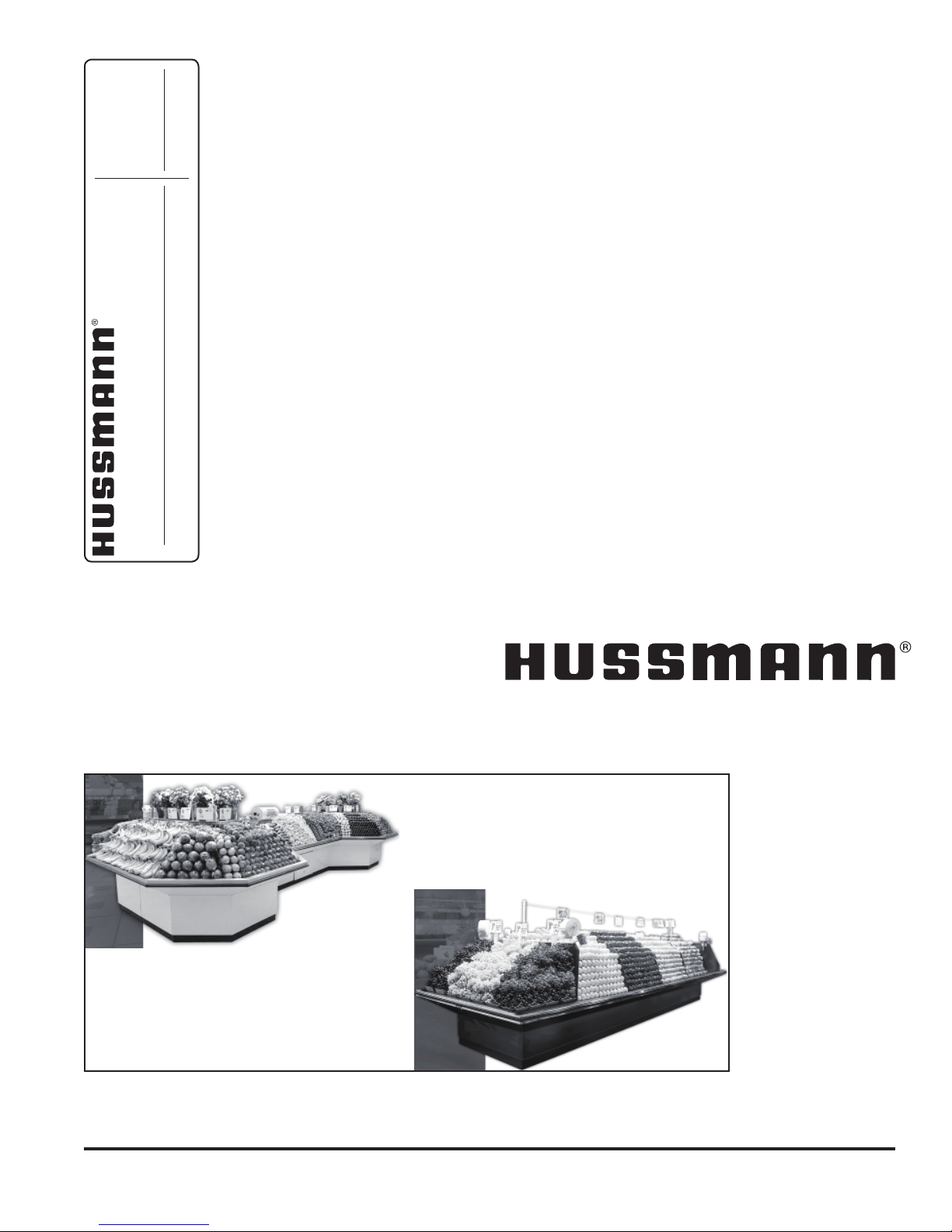
Manual
Installation
& Operation
REV. 0508
/CHINO
DBP, DBRP 01, 03
ISLAND PRODUCE
DBP, DBRP 01, 03
ISLAND PRODUCE
P/N IGIP-DBP, DBRP 01, 03-0508
INSTALLATION & OPERATION GUIDE
Page 2

General Instructions
This equipment is to be installed
to comply with the applicable
NEC, Federal, State , and Local
Plumbing and Construction
Code h a v ing j u risdicti o n .
Table of Contents
General Instructions.....................................................2
Cut and Plan Views ......................................................3
Installation .....................................................................4
Location ..................................................................................... 4
Uncrating the Stand ................................................................... 4
Exterior Loading ......................................................................... 4
Setting and Joining .................................................................... 5
Leveling .....................................................................................5
Splash Guard ............................................................................. 5
Plumbing ....................................................................... 6
Waste Outlet and P-TRAP ......................................................... 6
Access Panels ........................................................................... 6
Installing Condensate Drain....................................................... 6
Hose Reel .................................................................................. 6
Spray Hose ................................................................................ 6
Refrigeration ................................................................. 6
Refrigerant Type ........................................................................ 6
Piping ......................................................................................... 6
Access Panels ........................................................................... 6
Refrigeration Lines ..................................................................... 6
Control Settings ......................................................................... 6
Access to TX Valves and Drain Lines ........................................ 7
Electronic Expansion Valve (Optional) ....................................... 7
Thermostatic Expansion Valve Location .................................... 7
Measuring the Operating Superheat.......................................... 7
T-STAT Location ........................................................................ 7
Electrical........................................................................7
Wiring Color Code .....................................................................7
Electrical Circuit Identication .................................................... 7
Electrical Service Receptacles (When Applicable) .................... 7
Field Wiring and Serial Plate Amperage .................................... 8
Ballast Location .........................................................................8
Wiring and Serial Plate Amperage ............................................. 8
Ashrae Color Code .................................................................... 8
User Information ........................................................... 8
Stocking ..................................................................................... 8
Important Steps .........................................................................8
Case Cleaning ........................................................................... 8
Maintenance .................................................................. 9
Replacing Fluorescent Lamps ................................................... 9
Replacement Lamp Part List .....................................................9
T-5 Bulbs .................................................................................... 9
Evaporator Fans ........................................................................ 9
Copper Coils .............................................................................. 9
Tips and Troubleshooting ........................................................ 10
Electrical Wiring Diagrams ........................................10
Wiring Diagrams ......................................................... 11
Appendices ................................................................. 24
Appendix A. - Temperature Guidelines - Refrigerated ............. 24
Appendix B. - Application Recommendations - Refrigerated ... 24
Appendix C. - Field Recommendations - Refrigerated ............ 24
Appendix D. - Recommendations to User - Refrigerated ........ 25
IGIP-DBP, DBRP 01, 03-0508
This Booklet Contains Information on:
DBP, DBRP 01, 03 Island Produce Cases
Shipping Damage
All equipment should be thoroughly examined for shipping
damage before and during unloading.
This equipment has been carefully inspected at our factory
and the carrier has assumed responsibility for safe arrival.
If damaged, either apparent or concealed, claim must be
made to the carrier.
Apparent Loss or Damage
If there is an obvious loss or damage, it must be noted on
the freight bill or express receipt and signed by the carrier’s
agent; otherwise, carrier may refuse claim. The carrier will
supply necessary claim forms.
Concealed Loss or Damage
When loss or damage is not apparent until after equipment
is uncrated, a claim for concealed damage is made. Make
request in writing to carrier for inspection within 15 days,
and retain all packaging. The carrier will supply inspection
report and required claim forms.
Shortages
Check your shipment for any possible shortages of
material. If a shortage should exist and is found to be the
responsibility of Hussmann Chino, notify Hussmann Chino.
If such a shortage involves the carrier, notify the carrier
immediately, and request an inspection. Hussmann Chino
will acknowledge shortages within ten days from receipt
of equipment.
Hussmann Chino Product Control
The serial number and shipping date of all equipment
has been recorded in Hussmann’s les for warranty and
replacement part purposes. All correspondence pertaining
to warranty or parts ordering must include the serial number
of each piece of equipment involved, in order to provide
the customer with the correct parts.
Keep this booklet with the case at all times for future reference.
/CHINO
A publication of HUSSMANN® Chino
13770 Ramona Avenue • Chino, California 91710
(909) 628-8942 FAX
(909) 590-4910
(800) 395-9229
2
Page 3
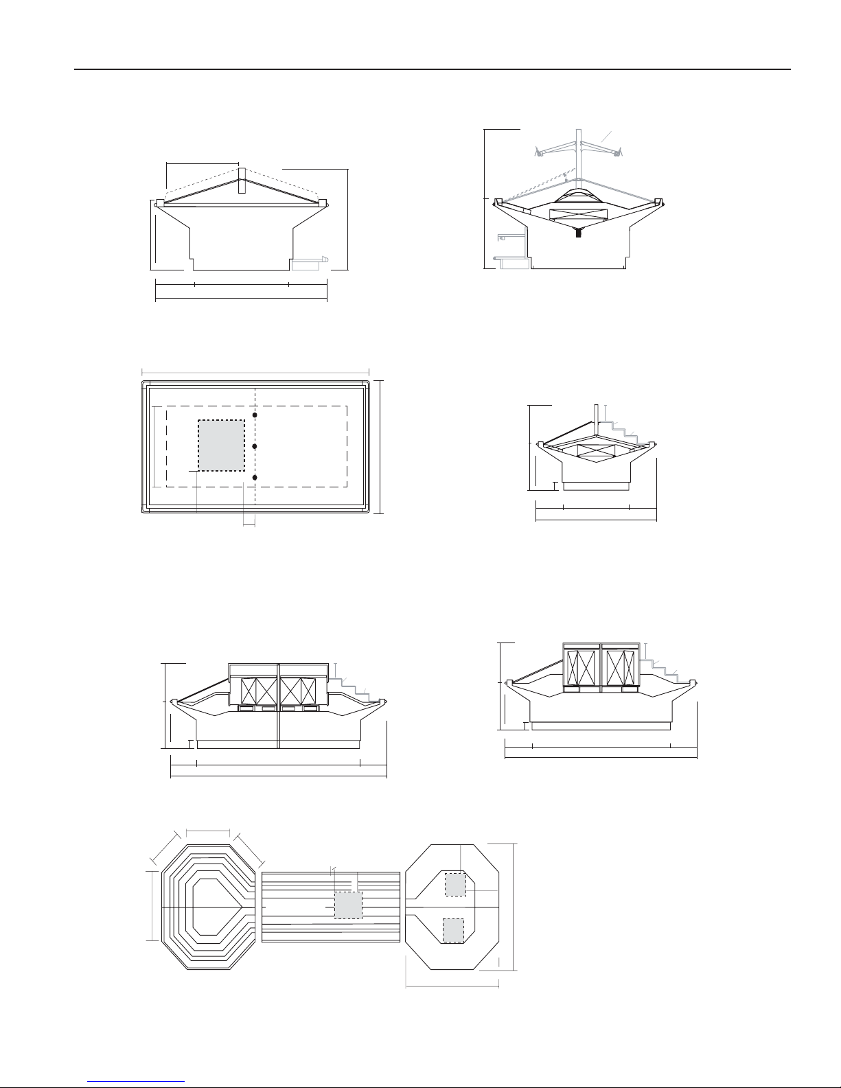
Rev. 0508
DBP-03
Standard Section
Produce
Scale = 3/8"
381/2"
701/4"
26
1
/
8
"
35
1
/
4
"
30"
153/
4
51"
3
/4"
Optional
Base Display
11"
141/4"
4"
26
1
/8
"
20
1
/
8"
5'-101/8"
41
5
/8"
DBRP
Straight Section
Scale = 1/4"
Straight
Racks
141/4"
4"
9"
73/8"
Optional
Step Racks
Mech.
stub-up
area
24" X 24"
C
L
70
1
/
4
"
DBRP-03
Plan View
NOTE: Mechanical Stub-Up Areas will vary with size of case
Scale = 1/4"
Variable
40"
Elec.
Drain
Ref.
6"
24"
1
6
"
26
1
/
8
"
DBRP-03
Shown with Optional
Ref. High Center Divider and
Refrigerated Lighted Shelves
Scale = 3/8”
30"
Optional Ref. High
Center Divider
and Ref. Lighted
Shelves
Optional
Base Display
C
L
DBP LINEUP
Modular Example
Scale = 1/8"
Crown
8'-73/4"
5’-9
1
/
2
"
10'-6
3
/
4
"
3
'
-
3
"
3'-3"
3'-101/2"
Center Display
Mech.
stub-up
area
6"
18"
18"
18"
Mech.
Stub-up
Area
24" X 24”
24"
X
24"
4"
DBRP
Crown Section
Scale = 1/4"
26
1
/8"
20
1
/
8
"
10'-63/4"
8'-1"
147/8"
73/8"
Straight
Racks
Optional
Step Racks
9"
4"
147/8"
DBRP
Octagon Section
Scale = 1/4"
Straight
Racks
Optional
Step Racks
4"
26
1
/
8
" 20
1
/
8
"
157/8"
9'-41/8"
6'-111/2" 157/8"
9"
7
3
/8"
4"
Cut and Plan Views
3
Page 4
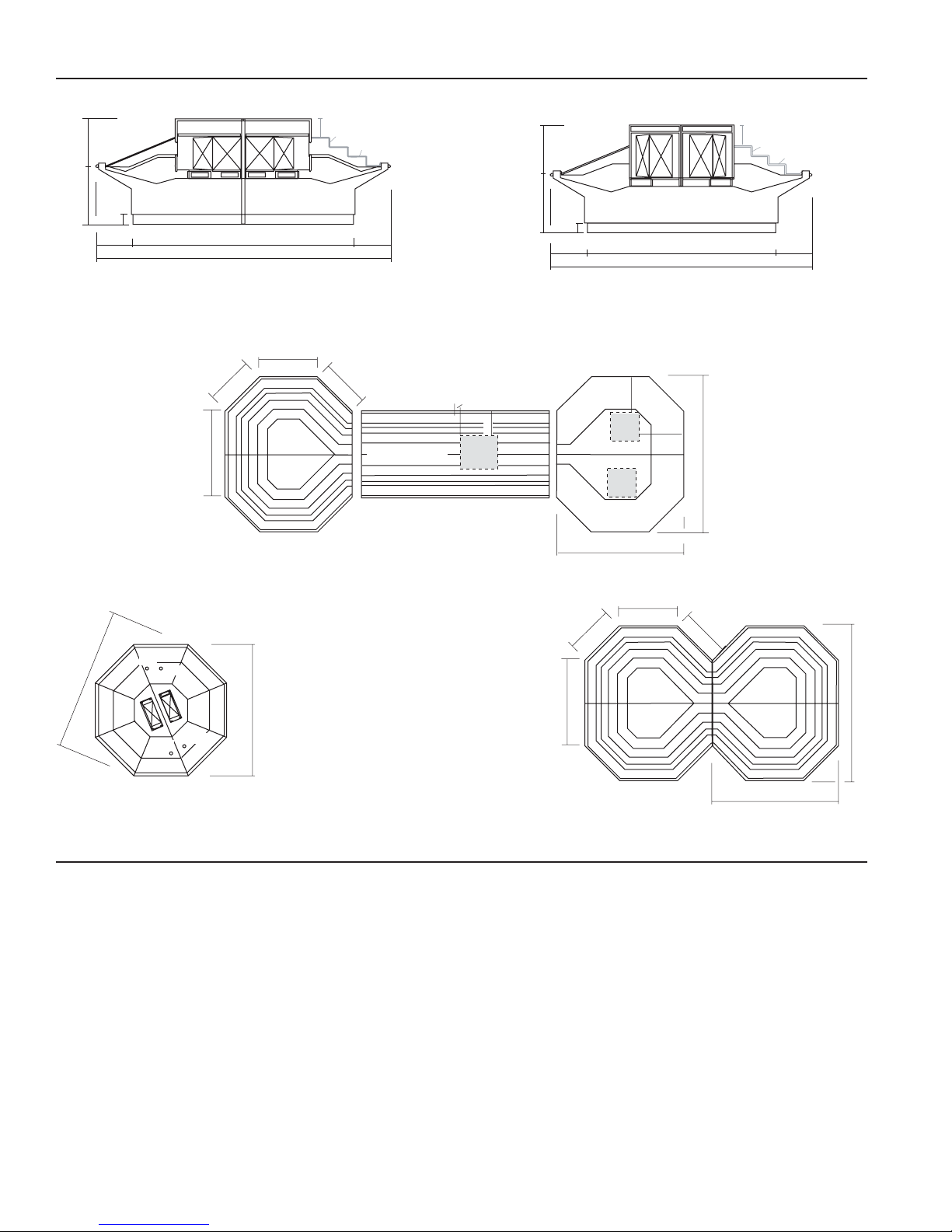
C
L
DBP LINEUP
Modular Example
Scale = 1/8"
Crown
8'-73/4"
5’-9
1
/
2
"
10'-6
3
/
4
"
3
'
-
3
"
3'-3"
3'-101/2"
Center Display
Mech.
stub-up
area
6"
18"
18"
18"
Mech.
Stub-up
Area
24" X 24”
24"
X
24"
4"
DBRP
Crown Section
Scale = 1/4"
26
1
/
8
"
20
1
/
8
"
10'-63/4"
8'-1"
14
7
/8"
7
3
/8"
Straight
Racks
Optional
Step Racks
9"
4"
147/8"
DBRP
Octagon Section
Scale = 1/4"
Straight
Racks
Optional
Step Racks
4"
26
1
/8" 20
1
/8"
157/8"
9'-41/8"
6'-11
1
/2" 157/8"
9"
73/8"
4"
9'-4
1
/
8
"
1
0
'
-
1
3
/
8
"
DBRP-OCTAGON
Plan View
Scale = 1/4"
Dra
in
Drain
R
e
f.
Elec
.
Crown
8'-73/4"
5'-9
1
/
2
"
10'-6
3
/
4
"
3
'-
3
"
3
'
-
3
"
3'-101/2"
DOUBLE DOG PLAN
Modular Example
Scal e = 1/8"
Cut and Plan Views (Cont'd)
IGIP-DBP, DBRP 01, 03-0508
Location
The refrigerated merchandisers have been designed
for use only in air conditioned stores where temperature
and humidity are maintained at or below 75°F and 55%
relative humidity. DO NOT allow air conditioning, electric
fans, ovens, open doors or windows (etc.) to create air
currents around the merchandiser, as this will impair its
correct operation.
Product temperature should always be maintained at a
constant and proper temperature. This means that from the
time the product is received, through storage, preparation
and display, the temperature of the product must be
controlled to maximize life of the product.
Installation
Uncrating the Stand
Place the xture as close to its permanent position as
possible. Remove the top of the crate. Detach the walls
from each other and remove from the skid. Unbolt the case
from the skid. The xture can now be lifted off the crate
skid. Lift only at base of stand!
Exterior Loading
These models have not been structurally designed to
support excessive external loading. Do not walk on their
tops; This could cause serious personal injury and damage
to the xture.
4
Page 5
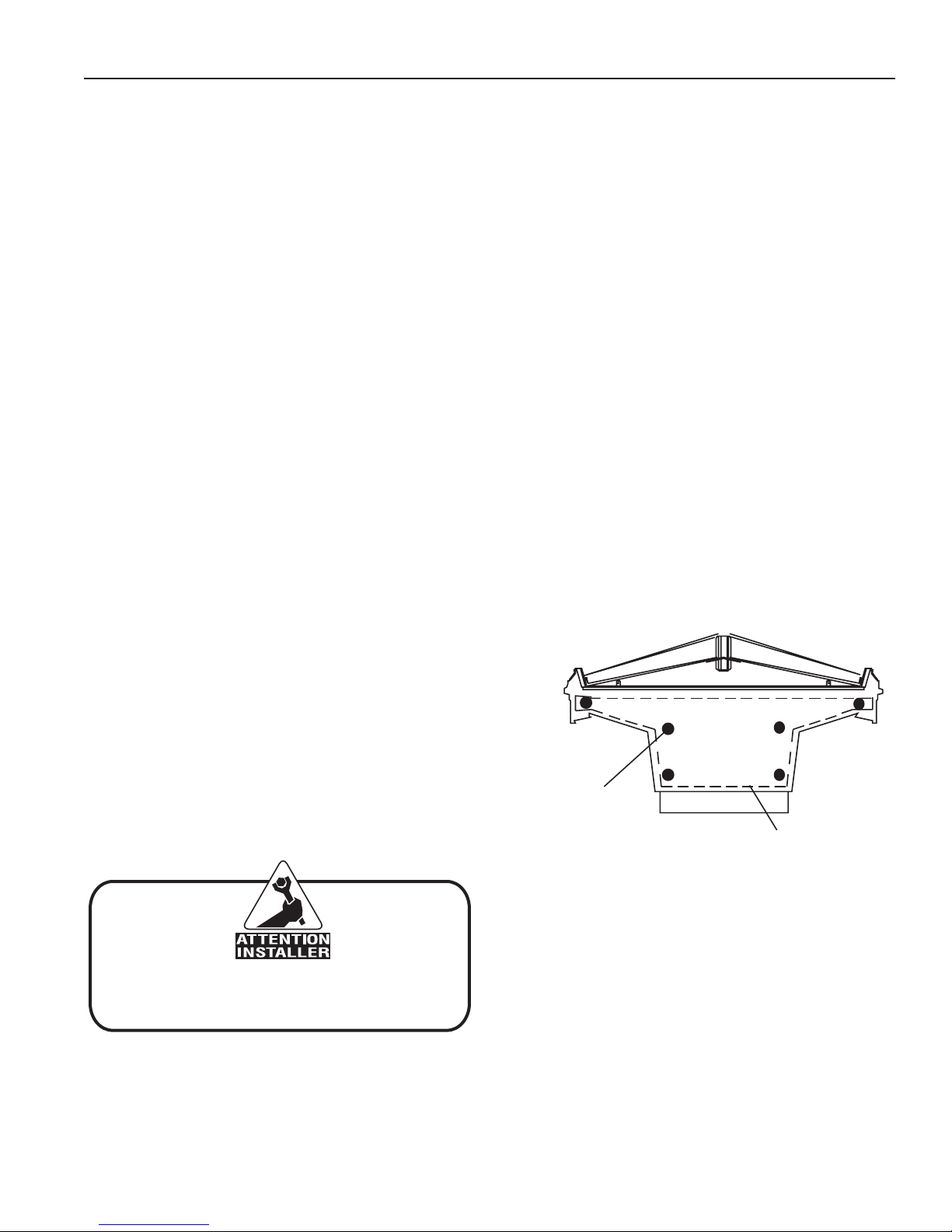
Rev. 0508
It is the contractor’s responsibility to install
case(s) according to local construction and
health codes
BO LT LO C ATIO N S
SE A L ANT A P PLIC ATIO N
Installation (Cont'd)
Setting and Joining
The sectional construction of these models enable them to
be joined in line to give the effect of one continuous display.
A joint trim kit is supplied with each joint.
Leveling
IMPORTANT! IT IS IMPERATIVE THAT CASES BE
LEVELED FROM FRONT TO BACK AND SIDE TO SIDE
PRIOR TO JOINING. A LEVEL CASE IS NECESSARY
TO INSURE PROPER OPERATION, WATER DRAINAGE,
GLASS ALIGNMENT, AND OPERATION OF THE HINGES
SUPPORTING THE GLASS. LEVELING THE CASE
CORRECTLY WILL SOLVE MOST HINGE OPERATION
PROBLEMS.
NOTE: A. To avoid removing concrete ooring, begin lineup
leveling from the highest point of the store oor.
B. When wedges are involved in a lineup, set them rst.
All cases were leveled and joined prior to shipment to
insure the closest possible t when cases are joined in
the eld. When joining, use a carpenters level and shim
legs accordingly. Case must be raised correctly, under legs
where support is best, to prevent damage to case.
1. Check level of oor where cases are to be set.
Determine the highest point of the oor; cases will
be set off this point.
2. Set rst case, and adjust legs over the highest part
of the oor so that case is level. Prevent
damage-case must be raised under leg or by use
of 2x6 or 2x4 leg brace. Remove side and back leg
braces after case is set.
3. Set second case as close as possible to the
rst case, and level case to the rst using the
instructions in step one.
4. Apply masking tape 1/8” in from end of case on
inside and outside rear mullion on both cases to be
joined.
5. Apply liberal bead of case joint sealant (butyl) to
(dotted area shown in gure) rst case. Apply heavy
amount to cover entire shaded area.
DO NOT USE PERMAGUM!
7. Apply bead of silicone to side of either half of case
(if case is built in two pieces). Also apply silicone to
seam between overhead light tubes.
8. Slide second half up to rst case snugly. To
compress silicone at joint, use two Jurgenson wood
clamps to pull the inside of the bulkheads together.
Make sure case is level from front to back and side
to side at joint. DO NOT USE BOLTS TO DRAW
CASES UP TIGHT! DAMAGE MAY OCCUR!
Make sure cases are tight and bolted together in all
locations (see diagram next page). Remove clamps.
Cleanup excess silicone.
9. There may be an interlock system built into the
tower, depending on the height of it. Joining involves
a number of bolts, again dependent on the height.
10. Attach joint trim pieces, that will hide the loose joint
where the case halves come together.
11. Connect case to eld electrical, refrigeration, and
pipe to oor sink.
12. Install body covers.
13. Attach cart bumper, if applicable.
Splash Guard
After cases have been leveled and joined, and refrigeration,
electrical, and wasted piping work completed, install the
splashguards. Fasten along the top edge, or center, with
#10 X 3/3” sheet metal screws.
DO NOT SEAL JOINT TRIM TO FLOOR!
6. Slide second case up to rst case snugly. Then level
second case to the rst case so glass front, bumper
and top are ush.
5
Page 6

Plumbing
IGIP-DBP, DBRP 01, 03-0508
Waste Outlet and P-TRAP
The waste outlet is located off the center of the case on
one side allowing drip piping to be run lengthwise under
the xture.
A 1-1/2” P-TRAP and threaded adapter are supplied with
each xture. The P-TRAP must be installed to prevent air
leakage and insect entrance into the xture.
NOTE: PVC-DWV solvent cement is recommended. Follow the
manufacturer’s instructions.
Access Panels
All electrical and drain access panels are clearly labeled on
the deck of the produce stand. The access for condensing
units (in the self contained units) is located on the side of
the stand, at the end. Ends of stand are tted for removal,
if condensing unit has to be taken out.
Installing Condensate Drain
Poorly or improperly installed condensate drains can
seriously interfere with the operation of this refrigerator, and
result in costly maintenance and product losses. Please
follow the recommendations listed below when installing
condensate drains to insure a proper installation:
1. Never use pipe for condensate drains smaller
than the nominal diameter of the pipe or P-TRAP
supplied with the case.
2. When connecting condensate drains, the P-TRAP
must be used as part of the condensate drain
to prevent air leakage or insect entrance. Store
plumbing system oor drains should be at least 14”
off the center of the case to allow use of the P-TRAP
pipe section. Never use two water seals in series in
any one line. Double P-TRAPS in series will cause a
lock and prevent draining.
Refrigeration
Refrigerant Type
The standard refrigerant will be R-22 unless otherwise
specied on the customer order. Check the serial plate on
the case for information.
Piping
The refrigerant line outlets are located under the case.
Locate rst the electrical box, the outlets are then on the
same side of the case but at the opposite end. Insulate
suction lines to prevent condensation drippage.
Access Panels
All electrical and drain access panels are clearly labeled on
the deck of the produce stand. The access for condensing
units (in the self contained units) is located on the side of
the stand, at the end. Ends of stand are tted for removal,
if condensing unit has to be taken out.
Refrigeration Lines
Liquid Suction
3/8” O.D. 5/8” O.D.
NOTE: The standard coil is piped at 5/8” (suction); however,
the store tie-in may vary depending on the number of
coils and the draw the case has. Depending on the case
setup, the connecting point in the store may be 5/8”, 7/8”,
or 11/8”. Refer to the particular case you are hooking up.
3. Always provide as much down hill slope (“fall”) as
possible; 1/8” per foot is the preferred minimum.
PVC pipe, when used, must be supported to
maintain the 1/8” pitch and to prevent warping.
4. Avoid long runs of condensate drains. Long runs
make it impossible to provide the “fall” necessary for
good drainage.
5. Provide a suitable air break between the ood rim of
the oor drain and outlet of condensate drain. 1” is
ideal.
6. Prevent condensate drains from freezing:
a. Do not install condensate drains in contact with
non-insulated suction lines. Suction lines should
be insulated with a non absorbent insulation
material such as Armstrong’s Armaex.
b. Where condensate drains are located in dead
air spaces (between refrigerators or between a
refrigerator and a wall), provide means to prevent
freezing. The water seal should be insulated to
prevent condensation.
Hose Reel
If an optional hose reel is ordered, it will be installed at the
factory. The water supply valve is located next to the access
panel. Connect the water supply to the valve.
Spray Hose
If an optional quick-disconnect spray hose is ordered, a
pressure regulating valve should be installed. If the water
pressure exceeds 45 PSI, the valve should be set for 30
to 35 PSI outlet pressure.
Refrigerant lines should be sized as shown on the
refrigeration legend furnished by the store.
Install P-TRAPS (oil traps) at the base of all suction line
vertical risers.
Pressure drop can rob the system of capacity. To keep the
pressure drop to a minimum, keep refrigerant line run as
short as possible, using the minimum number of elbows.
Where elbows are required, use long radius elbows only.
Control Settings
See DBP, DBRP 01, 03 technical data sheet for the
appropriate settings for your merchandiser. Maintain these
parameters to achieve near constant product temperatures.
Product temperature should be measured rst thing in
the morning, after having been refrigerated overnight.
For all multiplexing, defrost should be time terminated.
Loadmaster valves are not recommended. Defrost times
should be as directed in the DBP, DBRP 01, 03 technical
data sheet. The number of defrosts per day should never
change. The duration of the defrost cycle may be adjusted
to meet conditions present at your location.
6
Page 7
Rev. 0508
BEFORE SERVICING
ALWAYS DISCONNECT ELECTRICAL
POWER AT THE MAIN DISCONNECT
WHEN SERVICING OR REPLACING ANY
ELECTRICAL COMPONENT.
This includes (but not limited to) Fans, Heaters
Thermostats, and Lights.
Refrigeration (Cont'd)
Access to TX Valves and Drain Lines
Mechanical - Remove product from end of case. Remove
product racks. Remove refrigeration and drain access
panels (labeled). TX valve (mechanical only) and drain are
located under each access panel at end of the case.
Electronic - The Electronic Expansion valve master and
slave cylinder(s) are located within the electrical access
panel(s).
Electronic Expansion Valve (Optional)
A wide variety of electronic expansion valves and case
controllers can be utilized. Please refer to EEV and
controller manufacturers information sheet. Sensors for
electronic expansion valves will be installed on the coil inlet,
coil outlet, and in the discharge air. (Some supermarkets
require a 4th sensor in the return air). Case controllers will
be located in the electrical raceway or under the case.
Thermostatic Expansion Valve Location
This device is located on the same side as the refrigeration
stub. A balanced port expansion valve model is furnished
as standard equipment, unless otherwise specied by
customer.
Electrical
Expansion Valve Adjustment
Expansion valves must be adjusted to fully feed the
evaporator. Before attempting any adjustments, make
sure the evaporator is either clear or very lightly covered
with frost, and that the xture is within 10°F of its expected
operating temperature.
Measuring the Operating Superheat
1. Determine the suction pressure with an accurate
pressure gauge at the evaporator outlet.
2. From a refrigerant pressure temperature chart,
determine the saturation temperature at the
observed suction pressure.
3. Measure the temperature of the suction gas at the
thermostatic remote bulb location.
4. Subtract the saturation temperature obtained in step
No. 2 from the temperature measured in step No. 3.
5. The difference is superheat.
6. Set the superheat for 5°F - 7°F.
T-STAT Location
T-STATS are located under access panels on the end of
the case.
Wiring Color Code
CASE MUST BE GROUNDED
NOTE: Refer to label illustrated above that is afxed to case
to determine the actual conguration as checked in the
“TYPE INSTALLED” boxes.
Electrical Circuit Identication
Standard lighting for all models will be full length uorescent
lamps located within the case at the top.
The switch controlling the lights, the plug provided for
digital scale, and the thermometer are located at the rear
of the case mullion.
The receptacle that is provided on the exterior back of these
models is intended for computerized scales with a ve amp
maximum load, not for large motors or other high wattage
appliances. It should be wired to a dedicated circuit.
Electrical Service Receptacles (When Applicable)
The receptacles located on the exterior of the merchandiser
are intended for scales and lighted displays. They are not
intended nor suitable for large motors or other external
appliances.
7
Page 8
Electrical (Cont'd)
IGIP-DBP, DBRP 01, 03-0508
Field Wiring and Serial Plate Amperage
Field Wiring must be sized for component amperes printed
on the serial plate. Actual ampere draw may be less than
specied. Field wiring from the refrigeration control panel to
the merchandisers is required for refrigeration thermostats.
Case amperes are listed on the wiring diagram, but always
check the serial plate.
Ballast Location
Ballasts are located within the access panel that runs the
length of the rear of the case. Refer to diagram on page 5.
Wiring and Serial Plate Amperage
Field Wiring must be sized for component amperes stamped
on the serial plate. Actual ampere draw may be less than
specied. Field wiring from the refrigeration control panel to
the merchandisers is required for refrigeration thermostats.
Case amperes are listed on the wiring diagram, but always
check the serial plate.
User Information
Stocking
Improper temperature and lighting will cause serious
product loss. Discoloration, dehydration and spoilage
can be controlled with proper use of the equipment and
handling of product. Product temperature should always
be maintained at a constant and proper temperature.
This means that from the time the product is received,
through storage, preparation and display, the temperature
of the product must be controlled to maximize life of the
product. Hussmann cases were not designed to “heat up”
or “cool down” product-but rather to maintain an item’s
proper temperature for maximum shelf life. To achieve the
protection required always:
1. Minimize processing time to avoid damaging
temperature rise to the product. Product should be
at proper temperature.
2. Keep the air in and around the case area free
of foreign gasses and fumes or food will rapidly
deteriorate.
3. Maintain the display merchandisers temperature
controls as outlined in the refrigerator section of this
manual.
4. Do not place any product into these refrigerators
until all controls have been adjusted and they
are operating at the proper temperature. Allow
merchandiser to operate a minimum of 6 hours
before stocking with any product.
5. When stocking, never allow the product to extend
beyond the recommended load limit. Air discharge
and return air ue must be unobstructed at all
times to provide proper refrigeration.
Ashrae Color Code
NOTE: All other manufacturers have no standard sensor codes.
Case Control Systems SENSOR COLOR
Manufacturer ® > EIL CPC
Location
Coil Inlet
Coil Outlet
Discharge Air
Return Air
Defrost Term.
Liquid Line
Color Blue Blue
Part# 225-01-1755 225-01-3255
Color Red Red
Part# 225-01-1757 225-01-3123
Color Green Green
Part# 225-01-1756 225-01-3260
Color Purple Green
Part# 225-01-1758 225-01-3260
Color White Orange
Part# 225-01-0650 225-01-3254
Color White Blue
Part# 225-01-0650 225-01-3255
6. There are vents located at the base of the front of the
glass, just above the front rail. These vents supply a
continuous, gentle ow of air across the front glass
which inhibits condensation. Do not place any
signs or other restrictive objects on the front of
the refrigerator that will block these vents.
7. Avoid the use of supplemental ood or spot lighting.
Display light intensity has been designed for
maximum visibility and product life at the factory.
The use of higher output uorescent lamps (H.O.
and V.H.O.), will shorten the shelf life of the product.
8. Cold coils remove heat and moisture from the
case and deposit this as frost onto the coil. Thus, a
defrost is required. The only other moisture within
the case is that in the product itself. A single level of
meat will dry out faster than a fully loaded case of
3-4 levels of meat.
Important Steps
1. Do not set temperature too cold, as this causes
product dehydration. See Case Specs for Proper
Temperature: Settings.
Case Cleaning
Long life and satisfactory performance of any equipment
are dependent upon the care given to it. To insure long
life, proper sanitation and minimum maintenance costs,
the refrigerator should be thoroughly cleaned frequently.
SHUT OFF FAN DURING CLEANING PROCESS. It can be
unplugged within the case, or shut off case at the source.
The interior bottom may be cleaned with any domestic soap
or detergent based cleaners. Sanitizing solutions will not
harm the interior bottom, however, these solutions should
always be used according to the manufacturer’s directions.
It is essential to establish and regulate cleaning procedures.
This will minimize bacteria causing discoloration which
leads to degraded product appearance and signicantly
shortening product shelf life.
8
Page 9
Rev. 0508
CLEANING PRECAUTIONS
When cleaning:
• Do not use high pressure water hoses
• Do not introduce water faster than waste outlet can drain
• NEVER ON A SELF CONTAINED UNIT WITH AN EVAPORATOR FAN
• NEVER USE A CLEANING OR SANITIZING SOLUTION THAT HAS AN OIL
BASE (these will dissolve the butyl sealants) or an AMMONIA BASE
(this will corrode the copper componets of the case)
TO PRESERVE THE ATTRACTIVE FINISH:
• DO USE WATER AND A MILD DETERGENT FOR THE EXTERIOR ONLY
• DO NOT USE ABRASIVES OR STEEL WOOL SCOURING PADS
(these will mar the finish)
BEFORE SERVICING
ALWAYS DISCONNECT ELECTRICAL
POWER AT THE MAIN DISCONNECT
WHEN SERVICING OR REPLACING ANY
ELECTRICAL COMPONENT.
This includes (but not limited to) Fans, Heaters
Thermostats, and Lights.
This lamp has been treated to resist breakage and must be
replaced with a similarly treated lamp in order to maintain
compliance with NSF Standards. NSF CODE 4.28.1
Contact HUSSMANN Chino for replacement
1-800-395 -9 22 9 x 2131
User Information (Cont'd)
Soap and hot water are not enough to kill this bacteria. A
sanitizing solution must be included with each cleaning
process to eliminate this bacteria.
1. Scrub thoroughly, cleaning all surfaces, with soap
and hot water.
2. Rinse with hot water, but do not ood.
3. Apply the sanitizing solution according to the
manufacturer’s directions.
4. Rinse thoroughly.
5. Dry completely before resuming operation.
Maintenance
Replacement Lamp Part List
Refrigerated Lamps
Replacing Fluorescent Lamps
Fluorescent lamps are furnished with a shatterproof
protective coating. The same type of lamp with protective
coating must be used if replaced.
Lamp Q150T3/CL J220/230V150W/79
Our Part No. 125-03-1081 125-03-1141
Voltage 120VAC 220VAC
Rated Life 1500 Hrs 1500 Hrs
Manufacturer General electric Ushio America, Inc.
Our Cost $7.00 $2.55
Telephone 1-800-554-4680 1-800-760-7446
1-800-327-0097
General Electric has many national distribution locations.
Call for your closest location.
Ushio America Inc. is located at:
10550 Camden Drive.
Cypress, CA. 90630
T-5 Bulbs
Please note: T-5 lights must be turned off and on after bulb
replacement.
Evaporator Fans
The evaporator fans are located at the center front of these
merchandisers directly beneath the display pans. Should
fans or blades need servicing, always replace fan blades
with the raised embossed side of the blade TOWARD THE
MOTOR.
Copper Coils
The copper coils used in Hussmann merchandisers may
be repaired in the eld. Materials are available from local
refrigeration wholesalers.
Hussmann recommends using #15 Sil-Fos for repairs.
9
Page 10

FOR PROMPT SERVICE
When contacting the factory,
be sure to have the Case Model and Serial
Number handy. This information is on a plate
located on the case itself.
Maintenance (Cont'd)
Tips and Troubleshooting
Before calling for service, check the following:
1. Check electrical power supply to the equipment for
connection.
2. Check xture loading. Overstocking case will affect
its proper operation.
3. If frost is collecting on xture and/or product, check
that Humidity Control is working properly, and that
no outside doors or windows are open-allowing
moisture to enter store.
Electrical Wiring Diagrams
IGIP-DBP, DBRP 01, 03-0508
DBRP-01 Crown
2 Point
3 Point
8’
10’
12’
14’
Octagon ► 9’ Ø
DBRP-03 8’
32’
DBRP-03-SC-6x8-31”HRH 8’
DBRP-03-SC-6x8-31”HRH 8’
DBRP-03-12-SC 99 CENTS STORE 12’
W0500000
W0500001
W0500002
W0500003
W0500004
W0500005
W0500006
W0500007
W0500008
W0500020
W0500023
W0500024
W0500025
10
Page 11

Rev. 0508
DATE:
PROJECT TITLE:
DWG #:DRAWN BY:
PRODUCTION ORDER #:
DRAWING TITLE:
DATE:
REVISIONS:
:YB DEKCE
H
C:NOITPIRCSED :#
BY:
FILE LOCATION:
ADRIAN E. CRISCI
AEC
PAGE OF
HUSSMANN CORPORATION
13770 RAMONA AVENUE
CHINO, CA.91710
(909) 590-4910 LIC.#: 644406
1
2
3
1 1
03/19/02
H:\WIRESCHEMATICS\NEW-W IRING
DBRP-01 CASES
W0500000
CROWN CASE WIRING DIAGRAM
~ 115 VAC - 50/60 Hz.
L1 N
BUNDLE COLOR
BLACK / WHITE
T-STAT
SUCTION
SOLENOID
VALVE
FIXTURE LITHONIA
SM132 125-02-1072
FIXTURE LITHONIA
SM125 125-02-1073
SWITCH TOGGLE
125-01-0329
BUNDLE COLOR
BROWN
L1 N ~ 115 VAC - 50/60 Hz.
(OPTIONAL)
(OPTIONAL)
BUNDLE COLOR
ORANGE
L1 N ~ 115 VAC - 50/60 Hz.
CAP
CAP
TYPICAL 36" LEDGE
LIGHT (OPTIONAL)
TYPICAL 48" LEDGE
LIGHT (OPTIONAL)
EVAPORATOR FAN MOTORS
OPTIONAL LEDGE LIGHTING - MULTIPLE FIXTURES
ACCORDING TO CASE SHAPE AND SIZE.
(TYPICAL FIXTURES SHOWN)
M M M M M M
Wiring Diagrams
11
Page 12

DATE:
PROJECT TITLE:
DWG #:DRAWN BY:
PRODUCTION ORDER #:
DRAWING TITLE:
DATE:
REVISIONS:
:YB DEKCE
H
C:NOITPIRCSED :#
BY:
FILE LOCATION:
ADRIAN E. CRISCI
AEC
PAGE OF
HUSSMANN CORPORATION
13770 RAMONA AVENUE
CHINO, CA.91710
(909) 590-4910 LIC.#: 644406
1
2
3
1 1
03/19/02
H:\WIRESCHEMATICS\NEW-W IRING
DBRP-01 CASES
W0500001
2 POINT CASE WIRING DIAGRAM
~ 115 VAC - 50/60 Hz.
L1 N
BUNDLE COLOR
BLACK / WHITE
T-STAT
SUCTION
SOLENOID
VALVE
FIXTURE LITHONIA
SM132 125-02-1072
FIXTURE LITHONIA
SM125 125-02-1073
SWITCH TOGGLE
125-01-0329
BUNDLE COLOR
BROWN
L1 N ~ 115 VAC - 50/60 Hz.
(OPTIONAL)
(OPTIONAL)
BUNDLE COLOR
ORANGE
L1 N ~ 115 VAC - 50/60 Hz.
CAP
CAP
TYPICAL 36" LEDGE
LIGHT (OPTIONAL)
TYPICAL 48" LEDGE
LIGHT (OPTIONAL)
EVAPORATOR FAN MOTORS
OPTIONAL LEDGE LIGHTING - MULTIPLE FIXTURES
ACCORDING TO CASE SHAPE AND SIZE.
(TYPICAL FIXTURES SHOWN)
M M M M M M
Wiring Diagrams (Cont'd)
IGIP-DBP, DBRP 01, 03-0508
12
Page 13

Rev. 0508
DATE:
PROJECT TITLE:
DWG #:DRAWN BY:
PRODUCTION ORDER #:
DRAWING TITLE:
DATE:
REVISIONS:
:YB DEKCE
H
C:NOITPIRCSED :#
BY:
FILE LOCATION:
ADRIAN E. CRISCI
AEC
PAGE OF
HUSSMANN CORPORATION
13770 RAMONA AVENUE
CHINO, CA.91710
(909) 590-4910 LIC.#: 644406
1
2
3
1 1
03/19/02
H:\WIRESCHEMATICS\NEW-W IRING
DBRP-01 CASES
W0500002
3 POINT CASE WIRING DIAGRAM
~ 115 VAC - 50/60 Hz.
L1 N
BUNDLE COLOR
BLACK / WHITE
T-STAT
SUCTION
SOLENOID
VALVE
FIXTURE LITHONIA
SM132 125-02-1072
FIXTURE LITHONIA
SM125 125-02-1073
SWITCH TOGGLE
125-01-0329
BUNDLE COLOR
BROWN
L1 N ~ 115 VAC - 50/60 Hz.
(OPTIONAL)
(OPTIONAL)
BUNDLE COLOR
ORANGE
L1 N ~ 115 VAC - 50/60 Hz.
CAP
CAP
TYPICAL 36" LEDGE
LIGHT (OPTIONAL)
TYPICAL 48" LEDGE
LIGHT (OPTIONAL)
EVAPORATOR FAN MOTORS
OPTIONAL LEDGE LIGHTING - MULTIPLE FIXTURES
ACCORDING TO CASE SHAPE AND SIZE.
(TYPICAL FIXTURES SHOWN)
M M M M M M M
Wiring Diagrams (Cont'd)
13
Page 14

DATE:
PROJECT TITLE:
DWG #:DRAWN BY:
PRODUCTION ORDER #:
DRAWING TITLE:
DATE:
REVISIONS:
:YB DEKCE
H
C:NOITPIRCSED :#
BY:
FILE LOCATION:
ADRIAN E. CRISCI
AEC
PAGE OF
HUSSMANN CORPORATION
13770 RAMONA AVENUE
CHINO, CA.91710
(909) 590-4910 LIC.#: 644406
1
2
3
1 1
03/19/02
H:\WIRESCHEMATICS\NEW-W IRING
DBRP-01 CASES
W0500003
8' CASE WIRING DIAGRAM
~ 115 VAC - 50/60 Hz.
L1 N
BUNDLE COLOR
BLACK / WHITE
T-STAT
SUCTION
SOLENOID
VALVE
FIXTURE LITHONIA
SM132 125-02-1072
FIXTURE LITHONIA
SM125 125-02-1073
SWITCH TOGGLE
125-01-0329
BUNDLE COLOR
BROWN
L1 N ~ 115 VAC - 50/60 Hz.
(OPTIONAL)
(OPTIONAL)
BUNDLE COLOR
ORANGE
L1 N ~ 115 VAC - 50/60 Hz.
CAP
CAP
TYPICAL 36" LEDGE
LIGHT (OPTIONAL)
TYPICAL 48" LEDGE
LIGHT (OPTIONAL)
EVAPORATOR FAN MOTORS
OPTIONAL LEDGE LIGHTING - MULTIPLE FIXTURES
ACCORDING TO CASE SHAPE AND SIZE.
(TYPICAL FIXTURES SHOWN)
M M
Wiring Diagrams (Cont'd)
IGIP-DBP, DBRP 01, 03-0508
14
Page 15

Rev. 0508
DATE:
PROJECT TITLE:
DWG #:DRAWN BY:
PRODUCTION ORDER #:
DRAWING TITLE:
DATE:
REVISIONS:
:YB DEKCE
H
C:NOITPIRCSED :#
BY:
FILE LOCATION:
ADRIAN E. CRISCI
AEC
PAGE OF
HUSSMANN CORPORATION
13770 RAMONA AVENUE
CHINO, CA.91710
(909) 590-4910 LIC.#: 644406
1
2
3
1 1
03/19/02
H:\WIRESCHEMATICS\NEW-W IRING
DBRP-01 CASES
W0500004
10' CASE WIRING DIAGRAM
~ 115 VAC - 50/60 Hz.
L1 N
BUNDLE COLOR
BLACK / WHITE
T-STAT
SUCTION
SOLENOID
VALVE
FIXTURE LITHONIA
SM132 125-02-1072
FIXTURE LITHONIA
SM125 125-02-1073
SWITCH TOGGLE
125-01-0329
BUNDLE COLOR
BROWN
L1 N ~ 115 VAC - 50/60 Hz.
(OPTIONAL)
(OPTIONAL)
BUNDLE COLOR
ORANGE
L1 N ~ 115 VAC - 50/60 Hz.
CAP
CAP
TYPICAL 36" LEDGE
LIGHT (OPTIONAL)
TYPICAL 48" LEDGE
LIGHT (OPTIONAL)
EVAPORATOR FAN MOTORS
OPTIONAL LEDGE LIGHTING - MULTIPLE FIXTURES
ACCORDING TO CASE SHAPE AND SIZE.
(TYPICAL FIXTURES SHOWN)
M M M
Wiring Diagrams (Cont'd)
15
Page 16

DATE:
PROJECT TITLE:
DWG #:DRAWN BY:
PRODUCTION ORDER #:
DRAWING TITLE:
DATE:
REVISIONS:
:YB DEKCE
H
C:NOITPIRCSED :#
BY:
FILE LOCATION:
ADRIAN E. CRISCI
AEC
PAGE OF
HUSSMANN CORPORATION
13770 RAMONA AVENUE
CHINO, CA.91710
(909) 590-4910 LIC.#: 644406
1
2
3
1 1
03/19/02
H:\WIRESCHEMATICS\NEW-W IRING
DBRP-01 CASES
W0500005
12' CASE WIRING DIAGRAM
~ 115 VAC - 50/60 Hz.
L1 N
BUNDLE COLOR
BLACK / WHITE
T-STAT
SUCTION
SOLENOID
VALVE
FIXTURE LITHONIA
SM132 125-02-1072
FIXTURE LITHONIA
SM125 125-02-1073
SWITCH TOGGLE
125-01-0329
BUNDLE COLOR
BROWN
L1 N ~ 115 VAC - 50/60 Hz.
(OPTIONAL)
(OPTIONAL)
BUNDLE COLOR
ORANGE
L1 N ~ 115 VAC - 50/60 Hz.
CAP
CAP
TYPICAL 36" LEDGE
LIGHT (OPTIONAL)
TYPICAL 48" LEDGE
LIGHT (OPTIONAL)
EVAPORATOR FAN MOTORS
OPTIONAL LEDGE LIGHTING - MULTIPLE FIXTURES
ACCORDING TO CASE SHAPE AND SIZE.
(TYPICAL FIXTURES SHOWN)
M M M M
Wiring Diagrams (Cont'd)
IGIP-DBP, DBRP 01, 03-0508
16
Page 17

Rev. 0508
DATE:
PROJECT TITLE:
DWG #:DRAWN BY:
PRODUCTION ORDER #:
DRAWING TITLE:
DATE:
REVISIONS:
:YB DEKCE
H
C:NOITPIRCSED :#
BY:
FILE LOCATION:
ADRIAN E. CRISCI
AEC
PAGE OF
HUSSMANN CORPORATION
13770 RAMONA AVENUE
CHINO, CA.91710
(909) 590-4910 LIC.#: 644406
1
2
3
1 1
03/19/02
H:\WIRESCHEMATICS\NEW-W IRING
DBRP-01 CASES
W0500006
14' CASE WIRING DIAGRAM
~ 115 VAC - 50/60 Hz.
L1 N
BUNDLE COLOR
BLACK / WHITE
T-STAT
SUCTION
SOLENOID
VALVE
FIXTURE LITHONIA
SM132 125-02-1072
FIXTURE LITHONIA
SM125 125-02-1073
SWITCH TOGGLE
125-01-0329
BUNDLE COLOR
BROWN
L1 N ~ 115 VAC - 50/60 Hz.
(OPTIONAL)
(OPTIONAL)
BUNDLE COLOR
ORANGE
L1 N ~ 115 VAC - 50/60 Hz.
CAP
CAP
TYPICAL 36" LEDGE
LIGHT (OPTIONAL)
TYPICAL 48" LEDGE
LIGHT (OPTIONAL)
EVAPORATOR FAN MOTORS
OPTIONAL LEDGE LIGHTING - MULTIPLE FIXTURES
ACCORDING TO CASE SHAPE AND SIZE.
(TYPICAL FIXTURES SHOWN)
M M M M M
Wiring Diagrams (Cont'd)
17
Page 18

DATE:
PROJECT TITLE:
DWG #:DRAWN BY:
PRODUCTION ORDER #:
DRAWING TITLE:
DATE:
REVISIONS:
:YB DEKCE
H
C:NOITPIRCSED :#
BY:
FILE LOCATION:
ADRIAN E. CRISCI
AEC
PAGE OF
HUSSMANN CORPORATION
13770 RAMONA AVENUE
CHINO, CA.91710
(909) 590-4910 LIC.#: 644406
1
2
3
1 1
03/19/02
H:\WIRESCHEMATICS\NEW-W IRING
DBRP-01 CASES
W0500007
9' Ø - OCTAGON CASE WIRING DIAGRAM
~ 115 VAC - 50/60 Hz.
L1 N
BUNDLE COLOR
BLACK / WHITE
T-STAT
SUCTION
SOLENOID
VALVE
FIXTURE LITHONIA
SM132 125-02-1072
FIXTURE LITHONIA
SM125 125-02-1073
SWITCH TOGGLE
125-01-0329
M M M M M M M M
BUNDLE COLOR
BROWN
L1 N ~ 115 VAC - 50/60 Hz.
(OPTIONAL)
(OPTIONAL)
BUNDLE COLOR
ORANGE
L1 N ~ 115 VAC - 50/60 Hz.
CAP
CAP
TYPICAL 36" LEDGE
LIGHT (OPTIONAL)
TYPICAL 48" LEDGE
LIGHT (OPTIONAL)
EVAPORATOR FAN MOTORS
OPTIONAL LEDGE LIGHTING - MULTIPLE FIXTURES
ACCORDING TO CASE SHAPE AND SIZE.
(TYPICAL FIXTURES SHOWN)
Wiring Diagrams (Cont'd)
IGIP-DBP, DBRP 01, 03-0508
18
Page 19

Rev. 0508
DATE:
PROJECT TITLE:
DWG #:DRAWN BY:
PRODUCTION ORDER #:
DRAWING TITLE:
DATE:
REVISIONS:
:YB DEKCE
H
C:NOITPIRCSED :#
BY:
FILE LOCATION:
DENNY QUAN
---
PAGE OF
HUSSMANN CORPORATION
13770 RAMONA AVENUE
CHINO, CA.91710
(909) 590-4910 LIC.#: 644406
1
2
3
1 1
04/08/05
T:\WIRESCHEMATICS\NEW -WIRING
DBRP-03-8
W0500008
DBRP-03-8
######
COIL
PGS-2-3'-6"
115V 1 PHASE 50/60HZ
1.34 AMP
225-02-0040
M M
TERMINAL
BLOCK
125-01-0295
L1
L2
L3
N
G
POWER: ~115 VAC - 60 Hz. - 3 WIRE
CIRCUIT #1
NOTE:
CASE MUST
BE GROUNDED
1.4
#.#
#.#
L1L2L3
115 V
LOADING
Wiring Diagrams (Cont'd)
19
Page 20

DATE:
PROJECT TITLE:
DWG #:DRAWN BY:
PRODUCTION ORDER #:
DRAWING TITLE:
DATE:
REVISIONS:
:YB DEKCE
H
C:NOITPIRCSED :#
BY:
FILE LOCATION:
DENNY QUAN
---
PAGE OF
HUSSMANN CORPORATION
13770 RAMONA AVENUE
CHINO, CA.91710
(909) 590-4910 LIC.#: 644406
1
2
3
1 1
04/08/05
T:\WIRESCHEMATICS\NEW -WIRING
DBRP-03-32
W0500020
DBRP-03-32
######
COIL
PGS-2-3'-6"
115V 1 PHASE 50/60HZ
1.34 AMP
225-02-0040
M M
TERMINAL
BLOCK
125-01-0295
L1L2L3
N
G
POWER: ~115 VAC - 60 Hz. - 3 WIRE
M M M M M
M M M M M M M
CIRCUIT #1
NOTE:
CASE MUST
BE GROUNDED
9.4
#.#
#.#
L1L2L3
115 V
LOADING
Wiring Diagrams (Cont'd)
IGIP-DBP, DBRP 01, 03-0508
20
Page 21

Rev. 0508
DATE:
:# GWD:ELTIT TCEJORPDRAWN BY:
PRODUCTION ORDER #:
DRAWING TITLE:
DATE:
REVISIONS:
:YB DEKCEHC:NOITPIRCSED :# BY:
FILE LOCATION:
DENNY QUAN
---
PAGE OF
HUSSMANN CORPORATION
13770 RAMONA AVENUE
CHINO, CA.91710
(909) 590-4910 LIC.#: 644406
1
2
3
1 1
10/07/05
F:\WIRESCHEMATICS\NEW-WIRING
DBRP-03-SC-6x8-31"HRH
W0500023
DBRP-03-SC-6x8-31"HRH
561536
COIL
PGS-2-3'-6"
115V 1 PHASE 50/60HZ
1.34 AMP
225-02-0040
M M
TERMINAL
BLOCK
125-01-0295
L1
L2L3N
G
DEFROST TIMER
PARAGON 8045-20
~208 V - 60 Hz.
125-01-0715
M
YELLOW
C
2
1
3
R
S
POWER: ~208 / ~230 VAC - 60 Hz. - 4 WIRE
S
C
R
BLACK
START & RUN
CAPACITORS
5
21
RED
POWER SWITCH
POTENCIAL
RELAY
EXTERNAL
PROTECTOR
B
L
U
E
T
X
4
N
3
1
2
COMPRESSOR
MOTOR
CONDENSER FAN
~208 VAC
T-STAT P
RESSURE
SAFETY
CONDENSING UNIT
COPELAND
F2EM-A077-CAV-140
225-03-0041
CIRCUIT #1
NOTE:
CASE MUST
BE GROUNDED
13.2
11.8
#.#
11.7
10.5
#.#
L1
L2
L3
208 V 240 V
LOADING
Wiring Diagrams (Cont'd)
21
Page 22

DATE:
:# GWD:ELTIT TCEJORPDRAWN BY:
PRODUCTION ORDER #:
DRAWING TITLE:
DATE:
REVISIONS:
:YB DEKCEHC:NOITPIRCSED :# BY:
FILE LOCATION:
DENNY QUAN
---
PAGE OF
HUSSMANN CORPORATION
13770 RAMONA AVENUE
CHINO, CA.91710
(909) 590-4910 LIC.#: 644406
1
2
3
1 1
10/11/05
F:\WIRESCHEMATICS\NEW-WIRING
DBRP-03-SC-6x8-31"HRH
W0500024
DBRP-03-SC-6x8-31"HRH
COIL
PGS-2-3'-6"
115V 1 PHASE 50/60HZ
1.34 AMP
225-02-0040
M M
TERMINAL
BLOCK
125-01-0295
L1
L2L3N
G
DEFROST TIMER
PARAGON 8045-20
~208 V - 60 Hz.
125-01-0715
M
YELLOW
C
2
1
3
R
S
POWER: ~208 / ~230 VAC - 60 Hz. - 4 WIRE
S
C
R
BLACK
START & RUN
CAPACITORS
5
21
RED
POWER SWITCH
POTENCIAL
RELAY
EXTERNAL
PROTECTOR
B
L
U
E
T
X
4
N
3
1
2
COMPRESSOR
MOTOR
CONDENSER FAN
~208 VAC
T-STAT P
RESSURE
SAFETY
CONDENSING UNIT
COPELAND
1 HP
F3AM-A101-CFV-001
11.8 AMP @230 VAC
225-03-0110
CIRCUIT #1
NOTE:
CASE MUST
BE GROUNDED
13.2
11.8
#.#
11.7
10.5
#.#
L1
L2
L3
208 V 240 V
LOADING
Wiring Diagrams (Cont'd)
IGIP-DBP, DBRP 01, 03-0508
22
Page 23

Rev. 0508
DATE:
PROJECT TITLE:
DRAWING #:
DRAWN BY:
PRODUCTION ORDER #:
DRAWING TITLE:
DATE:
Hussmann Corporation, Int'l.
13770 Ramona Avenue
Chino, CA. 91710
(909)-590-4910 Lic.#: 644406
REVISIONS:
#: DESCRIPTION:
CHECKED BY:
BY:
FILE LOCATION:
JESSE RIOS
PAGE OF1
1
6/11/07
99 CENTS STORE
W0500025
DBRP-03-12-SC
885806
B Revised Condenser fan wiring scheme
6/29/07 JR
C Updated dwg to match UL test report 1/10/08 JR
DEFROST TIMER
PARAGON 8045-20
~208 V - 60 Hz.
125-01-0715
POWER SWITCH
125-01-0271
T-STAT
225-01-2010
PRESSURE
SAFETY
225-01-0706B
GE FAN 9W
(4)125-01-0615A
.60A
CONDENSING UNIT
COPELAND FJAM-A150-CFV-020
225-03-7510
RLA= 10.9A
MCC= 15.7A
LRA= 56 A
M
C
R
CONDENSING UNIT
SAFETY
SWITCH
FLOAT SWITCH
FISHER™ EVAPOWAY™
DM20WW-3D
2000W @ ~ 240 VAC
8.33A
125-01-0500
BUNDLE
BROWN
LABELED
FAN CIRCUIT
BUNDLE
PURPLE
LABELED
EVAP PAN
CIRCUIT
BUNDLE BLUE
LABELED
CONDENSING
UNIT CIRCUIT
~208 / 240 VAC - 50/60 Hz.
BLACK #14
BLACK # 14
RED # 14
BLACK # 14
RED # 14
M M
M
M
T
X
4
N
3
1
2
CIRCUIT #1
GREEN # 10
L1
L2
N
G
WHITE # 14
BLACK # 10
RED # 10
15A
(4) 15A FUSE
125-01-8604
(2)15A FUSE
HOLDER
125-01-8610
FUSE
15A
15A
15A
15A
15A FUSE
125-01-8604
15A FUSE
HOLDER
125-01-8605
FUSE
CIRCUIT #1
NOTE:
CASE MUST
BE GROUNDED
21.6
19.2
20.5
18.1
L1
L2
L3
208 V 240 V
LOADING
Wiring Diagrams (Cont'd)
23
Page 24

Appendices
IGIP-DBP, DBRP 01, 03-0508
Appendix A. - Temperature Guidelines - Refrigerated
The refrigerators should be operated according to the
manufacturer’s published engineering specications for
entering air temperatures for specic equipment applications.
Table 1 shows the typical temperature of the air entering the
food zone one hour before the start of defrost and one hour
after defrost for various categories of refrigerators. Refer to
Appendix C for Field Evaluation Guidelines.
Table 1
Type of Refrigerator
I. OPEN DISPLAY
A. Non frozen:
1) Meat 28°F
2) Dairy/Deli 32°F
3) Produce
a. Processed 36°F
b. Unprocessed 45°F
B. Frozen 0°F
C. Ice Cream -5°F
II. CLOSED DISPLAY
A. Non frozen:
1) Meat 34°F
2) Dairy/Deli 34°F
3) Produce
a. Processed 36°F
b. Unprocessed 45°F
B. Frozen 0°F
C. Ice Cream -5°F
Single Deck Multi Deck Service Case Reach-In
I. Open Display Styles II. Closed Display Styles
Typical Entering
Air Temperature
Appendix B. - Application Recommendations Refrigerated
1.0 Temperature performance is critical for controlling
bacteria growth. Therefore, the following
recommendations are included in the standard.
They are based on conrmed eld experience
over many years.
1.1 The installer is responsible for following the
installation instructions and recommendations
provided by Hussmann for the installation
of each individual type refrigerator.
1.2
Refrigeration piping should be sized according to
the equipment manufacturer’s recommendations
and installed in accordance with normal
refrigeration practices. Refrigeration piping
should be insulated according to Hussmann’s
recommendations.
1.3 A clogged waste outlet blocks refrigeration. The
installer is responsible for the proper installation
of the system which dispenses condensate waste
through an air gap into the building indirect waste
system.
1.4 The installer should perform a complete start-up
evaluation prior to the loading of food into the
refrigerator, which includes such items as:
a) Initial temperature performance, Coils should
be properly fed with a refrigerant according to
manufacturer’s recommendations.
b) Observation of outside inuences such
as drafts, radiant heating from the ceiling
and from lamps. Such inuence should be
properly corrected or compensated for.
c) At the same time, checks should be made of
the store dry-bulb and wet-bulb temperatures
to ascertain that they are within the limits
prescribed by Hussmann.
d) Complete start-up procedures should include
checking through a defrost to make certain
of its adequate frequency and length without
substantially exceeding the actual needs.
This should include checking the electrical
or refrigerant circuits to make sure that
defrosts are correctly programmed for all the
refrigerators connected to each refrigeration
system.
e) Recording instruments should be used to
check performance.
Appendix C. - Field Recommendations - Refrigerated
Recommendations for eld evaluating the
performance of retail food refrigerators and hot
cases
1.0 The most consistent indicator of display
refrigerator performance is temperature of the air
entering the product zone (see Appendix A). In
practical use, the precise determination of return
air temperature is extremely difcult. Readings of
return air temperatures will be variable and results
will be inconsistent. The product temperature
alone is not an indicator of refrigerator
performance.
NOTE: Public Health will use the temperature of the product in
determining if the refrigerator will be allowed to display
potentially hazardous food. For the purpose of this
evaluation, product temperature above the FDA Food
Code 1993 temperature for potentially hazardous food
will be the rst indication that an evaluation should
be performed. It is expected that all refrigerators will
keep food at the FDA Food Code 1993 temperature for
potentially hazardous food.
24
Page 25

Rev. 0508
Appendices (Cont'd)
1.1 The following recommendations are made
for the purpose of arriving at easily taken and
understood data which, coupled with other
observations, may be used to determine whether
a display refrigerator is working as intended:
a) INSTRUMENT - A stainless steel stem-type
thermometer is recommended and it should
have a dial a minimum of 1 inch internal
diameter. A test thermometer scaled only
in Celsius or dually scaled in Celsius and
Fahrenheit shall be accurate to 1°C (1.8°F).
Temperature measuring devices that are
scaled only in Fahrenheit shall be accurate to
2°F. The thermometer should be checked for
proper calibration. (It should read 32°F when
the stem is immersed in an ice water bath).
b) LOCATION - The probe or sensing element
of the thermometer should be located in
the airstream where the air rst enters the
display or storage area, and not more than
1 inch away from the surface and in the
center of the discharge opening.
c) READING - It should rst be determined
that the refrigerator is refrigerating and has
operated at least one hour since the end
of the last defrost period. The thermometer
reading should be made only after it has
been allowed to stabilize, i.e., maintain a
constant reading.
d) OTHER OBSERVATIONS - Other
observations should be made which may
indicate operating problems, such as
unsatisfactory product, feel/appearance.
e) CONCLUSIONS - In the absence of any
apparent undesirable conditions, the
refrigerator should be judged to be operating
properly. If it is determined that such
condition is undesirable, i.e., the product is
above proper temperature, checks should be
made for the following:
1. Has the refrigerator been loaded with warm
product?
2. Is the product loaded beyond the “Safe Load
Line” markers?
3. Are the return air ducts blocked?
4. Are the entering air ducts blocked?
5.
Is a dumped display causing turbulent air ow and
mixing with room air?
6. Are spotlights or other high intensity lighting
directed onto the product?
7. Are there unusual draft conditions (from heating/
air-conditioning ducts, open doors, etc.)?
8. Is there exposure to direct sunlight?
9. Are display signs blocking or diverting airow?
10. Are the coils of the refrigerator iced up?
11. Is the store ambient over 75°F, 55% RH as set
forth in ASHRAE Standard 72 and ASHRAE
Standard 117?
12. Are the shelf positions, number, and size other
than recommended by Hussmann?
13. Is there an improper application or control
system?
14. Is the evaporator fan motor/blade inoperative?
15. Is the defrost time excessive?
16. Is the defrost termination, thermostat (if used) set
too high?
17. Are the refrigerant controls incorrectly adjusted?
18. Is the air entering the condenser above design
conditions? Are the condenser ns clear of dirt,
dust, etc.?
19. Is there a shortage of refrigerant?
20. Has the equipment been modied to use
replacements for CFC-12, CFC-502 or other
refrigerant? If so, have the modications been
made in accordance with the recommendations of
the equipment manufacturer? Is the refrigerator
charged with the proper refrigerant and lubricant?
Does the system use the recommended
compressor?
Appendix D. - Recommendations to User Refrigerated
1.0 Hussmann Corporation provides instructions
and recommendations for proper periodic
cleaning. The user will be responsible for
such cleaning, including the cleaning of low
temperature equipment within the compartment
and the cooling coil area(s). Cleaning practices,
particularly with respect to proper refrigerator
unloading and warm-up, must be in accordance
with applicable recommendations.
25
Page 26

Appendices (Cont'd)
IGIP-DBP, DBRP 01, 03-0508
1.1 Cleaning of non frozen food equipment
should include a weekly cleaning of the food
compartment as a minimum to prevent bacteria
growth from accumulating. Actual use and
products may dictate more frequent cleaning.
Circumstances of use and equipment design
must also dictate the frequency of cleaning the
display areas. Weekly washing down of the
storage compartment is also recommended,
especially for equipment subject to drippage
of milk or other liquids, or the collection of
vegetable, meat, crumbs, etc. or other debris
or litter. Daily cleaning of the external areas
surrounding the storage or display compartments
with detergent and water will keep the equipment
presentable and prevent grime buildup.
1.2 Load levels as dened by the manufacturer must
be observed.
1.3 The best preservation is achieved by following
these rules:
a) Buy quality products.
b) Receive perishables from transit equipment
at the ideal temperature for the particular
product.
c) Expedite perishables to the store’s storage
equipment to avoid unnecessary warm-up
and prolonged temperature recovery. Food
store refrigerators are not food chillers nor
can they reclaim quality lost through previous
mishandling.
d) Care must be taken when cross
merchandising products to ensure that
potentially hazardous vegetable products are
not placed in non refrigerated areas.
e) Display and storage equipment doors should
be kept closed during periods of inactivity.
f) Minimize the transfer time of perishables
from storage to display.
g) Keep meat under refrigeration in meat cutting
and processing area except for the few
moments it is being handled in processing.
When a cut or tray of meat is not to be
worked on immediately, the procedure should
call for returning it to refrigeration.
h) Keep tools clean and sanitized. Since
mechanical equipment is used for fresh
meat processing, all such equipment should
be cleaned at least daily and each time
a different kind of meat product comes in
contact with the tool or equipment.
i) Make sure that all refrigeration equipment is
installed and adjusted in strict accordance
with the manufacturer’s recommendations.
j) See that all storage and refrigeration
equipment is kept in proper working order by
routine maintenance.
For further technical information, please log on to http://www.hussmann.com/products/DBP-03.htm
26
Page 27

IGIP-DBP, DBRP 01, 03-0508
Service Record
Last service date: By:
_______________ __________________________________________________________________________________________________
_______________ __________________________________________________________________________________________________
_______________ __________________________________________________________________________________________________
_______________ __________________________________________________________________________________________________
_______________ __________________________________________________________________________________________________
_______________ __________________________________________________________________________________________________
_______________ __________________________________________________________________________________________________
/Chino
Additional copies of this publication may be obtained by contacting:
Hussmann® Chino
13770 Ramona Avenue • Chino, California 91710
(909) 628-8942 FAX
(909) 590-4910
(800) 395-9229
The MODEL NAME and SERIAL NUMBER is required in order to provide
you with the correct parts and information for your particular unit.
They can be found on a small metal plate on the unit.
Please note them below for future reference.
MODEL:
SERIAL NUMBER:
 Loading...