

Page 1
For Medium Temperature Merchandisers
D5ELE/D5EE END CASES
TO D5 PARENT CASE
JOINING INSTRUCTION
HUSSMANN CORPORATION • BRIDGETON, MO 63044-2483 (Printed in U.S.A.)
®
1
B
e sure Merchandisers have
been leveled according to the
installation instructions.
Carefully unpack and inspect
the Joint Kit making sure
there is no breakage or
damage.
1
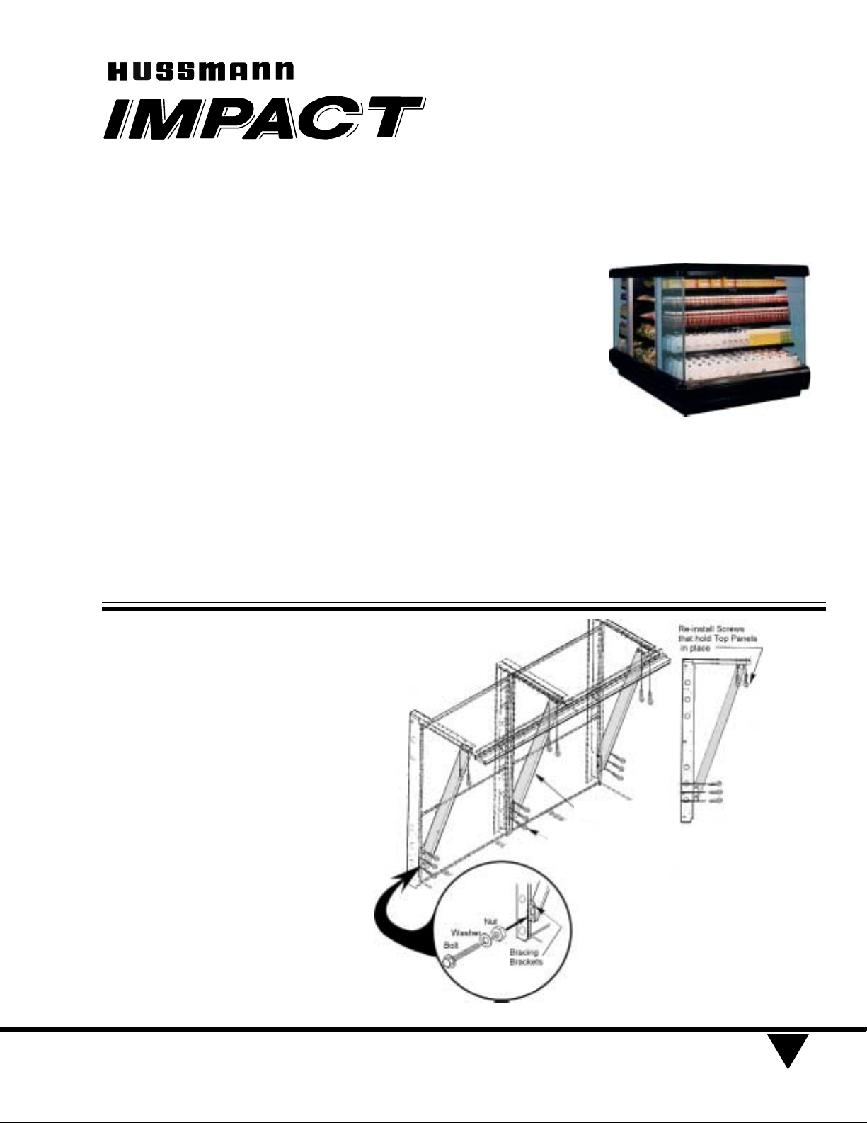
REMOVING SHIPPING BRACES .
Remove Bolts, Washers and
Nuts from Shipping Braces.
Then remove the shipping
brace Brackets. See Figure 1
and Detail A.
After removing the braces
and brackets, make sure to
replace the screws that hold
the top panels in place.
July, 2000
P/N 407199
JOINT KIT
JOINT KIT
Fig. 1. Removing Shipping Braces
Side View
Bracing
PARTS LIST
Item Quantity Description
19" Front 23" Front
1. 1 1 Gasket
1
/
2
x
1
/
2
x 60
2. 1 1 Gasket
1
/
2
x 1
5
/
8
x 120
3. 4 4 Joining Brackets
4. 12 12 Hex Washer Head SM Screw
3
/
4
10 -16
5 2 4 Cap Screw
5
/16 -18 x 4
6. 2 4 Flat Washer
5
/16
7. 8 8 Cap Screw
1
/4
- 20 x 1
8. 8 8 Flat Washer
1
/4
9. 2 2 Cap Screw
5
/16
- 18 x 2
1
/
2
10. 4 4 Flat Washer
5
/16
11. 2 2 Lock Washer
5
/16
12 2 2 Hex Nut
5
/16
- 18
13. 2 2 Threaded Rod
1
/2
-13 x 15
14. 4 4 Flat Washer
1
/2
15. 4 4 Hex Nut
1
/2 -13
16. 1 1 Butyl Tape
17. 2 2 Splashguard Joint Support
18. 8 8 Hex Head Sheet metal Screw #8 x
1
/2
Note: Nut retainers are factory installed in the left end, and alignment pins are factory installed in the right end of each
merchandiser.
Detail A
Sheet Metal
Screws
Page 2
P/N 407199
HUSSMANN CORPORATION • BRIDGETON, MO 63044-2483 (Printed in U.S.A.)
2
2
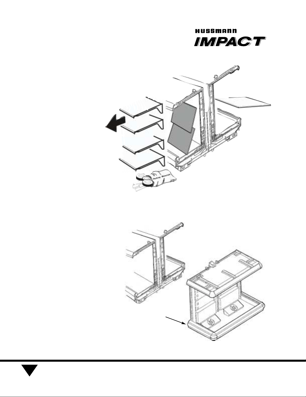
REMOVING CASE COMPONENTS.
Remove shelves (if they are
installed), display racks, pans,
front shelf supports and front
air grilles from the right end.
Remove the rear panels at the
RIGHT end:
Remove the lower back
panel first by lifting up from
its bottom edge and out. Do
not use sharp tools.
Remove the rear panels at
the RIGHT end:
Lift the upper back panel up
and out.
See Figure 2.
3
Check that the Nut Retainers
are in place in the bottom of
the merchandiser at locations
shown in Figure 3.
Fig. 2. Removing Components from Case
Retainer Clips here
both sides.
(2) on D5ELE
(4) on D5 EE
See Detail “B”
page 5.
Fig. 3. Locating Nut Retainers
®
Merchandisers
Page 3
4
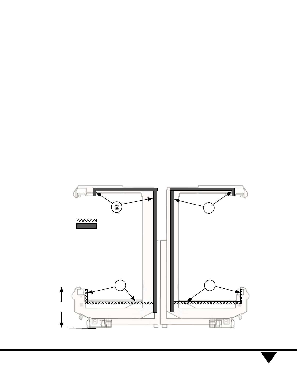
Apply Gasket - 1 in the horizontal recess across the bottom
and up front to cover slots.
Apply Gasket - 2 to cover
foam -to- metal gap at rear
and across top as shown. Lap
gaskets at lower corners.
Check that there are no gaps
between gasket and merchandiser.
Do not stretch gasket, espe-
cially around corners.
Do not butt gaskets; always
overlap joints.
Remove paper backing after
gasket is applied.
HUSSMANN CORPORATION • BRIDGETON, MO 63044-2483 (Printed in U.S.A.)
3
D5ELE/D5EE END CASES TO D5 PARENT CASE
JOINING INSTRUCTION
P/N 407199
Fig. 4. Installing Gasket
Gasket
D5 Parent
Case
23”
2
1
2
1
2
1
Page 4

5
Move second merchandiser
against first, mating alignment
pins with corresponding holes
N
OTE: WHEN BOLTING THE CASES
TOGETHER
, BE SURE TO FOLLOW
THE SEQUENCE SHOWN BELOW IN
FIGURE 5 AND ON PAGE
5.
6
Install (4)
Joining Brackets - 3, using
Screws - 4 as shown in
Figure 5 below.
P/N 407199
HUSSMANN CORPORATION • BRIDGETON, MO 63044-2483 (Printed in U.S.A.)
Model D5ELE
End Case
A
E
B
C
D
F
Model D5L
Parent Case
Joining
Brackets
(1) each on
Parent case
Joining
Brackets
(2) on
End Case
4
Fig. 5. Sequence of bolting cases together
T op V iew
Joining Brackets
(3) Screws each
®
Merchandisers
Page 5

6
Fasten fronts together using
Cap Screw – 5 and Flat
Washers – 6. Tighten only
until front panels touch. Do not
tighten fully. See Detail B.
7
Use Cap Screws – 7 with
Flat Washers – 8 to draw
merchandisers together at
rear. Start at the bottom,
below the coil baffle, then
middle, then top; tighten until
gaskets are compressed. See
Detail C.
8
Use Cap Screws – 9 with
Flat Washers – 10, Lock
Washers – 11 and Hex Nut 12 to join and bolt merchand-
isers together at rear top. See
Detail D.
9
Draw canopies together using
Rod – 13 through top shoe,
and Washers – 14, and
Nuts – 15 on each end of rod
Stop when canopies touch.
See Detail E.
HUSSMANN CORPORATION • BRIDGETON, MO 63044-2483 (Printed in U.S.A.)
5
6
5
Retainer Nut
6
5
12
13 14
7
8
11
10
9
6
5
7
8
11
10
9
13 14 15
Alignment
Pin
Alignment
Pin
7
8
D5EE Case Model
15
Detail B
Detail B
Detail C
Detail C
Detail E
Detail D
Detail D
12
Detail E
Fig. 6. Bolting Cases Together
13
14
15
14
15
14
15
14
15
13
Detail E
D5ELE/D5EE END CASES TO D5 PARENT CASE
JOINING INSTRUCTION
P/N 407199
Detail C
Detail B
Detail D
Detail E
12
11
DETAIL D
10
9
Page 6

P/N 407199
®
HUSSMANN CORPORATION • BRIDGETON, MO 63044-2483 (Printed in U.S.A.)
6
10
Apply Butyl Tape – 16
across bottom joint, extending up at back and front. Use
field-supplied silicone in any
gap between front support
brackets. See Figure 7.
11
Refer to I/O manual to install
splashguard brackets.
Install Splashguard Joint
Support – 17 using
Screws – 18.
See Figure 8.
12
Install splashguards and
lower front panels according
to I/O manual. See Figure 9.
Fig. 7. Applying the Butyl Tape
Fig. 9. Installing Splashguards
Fig. 8. Installing Splashguard Retainers
16
Typical both sides
Merchandisers
Page 7

13
Refer to Poster 389043 or
I/O manual or to remove and
install top rail and bumpers.
Install upper bumper and bumper
trim on end of case both sides.
Push int o place. Slide internal
bumper trim under end of upper
bumper. Install full length
bumpers and trim flush and offset
across joints, making sure no gaps
exist between sections. Push into
place.
Install lower bumper on end case
both sides. Push into place. Add
full length bumpers flush with
bumper and offset across joints,
making sure no gaps exist
between sections. Push into place.
Install top rail on end case both
sides; push front down over color
panel until snap, then push rear
over light channel until snap.
Add full length top rail flush and
offset across joint.
R
EFRIGERATE CASE LINEUP AND
LAST SECTIONS FOR AT LEAST
6
HOURS.
Before installing last sections, tap the
right end of top rail and bumpers to
close any gaps. Measure between
right end and installed rail or bumper .
Use a miter box and fine-toothed saw
to cut last bumpers to length.
Before installing last section of upper
bumper, install internal trim flush to
right end, then install cut bumper.
HUSSMANN CORPORATION • BRIDGETON, MO 63044-2483 (Printed in U.S.A.)
7
P/N 407199
D5ELE/D5EE END CASES TO D5 PARENT CASE
JOINING INSTRUCTION
Fig. 10. Installing Bumpers and Top Rails
Top Rail
Bumpers
 Loading...