

Page 1

B
D
C
E
D
A
E
E
C2SLE
Data Sheet Set
P/N 0408922
NSF
®
Certified
November, 2002
P/N 0408922
Note: Changed items have been underlined.
®
HUSSMANN CORPORATION, Bridgeton, MO 63044-2483 U.S.A.
Item Part # Description Wiring Item #
FAN ASSEMBLIES, AND THERMOSTATS
A. 6W Fan Assembly (1)
0058698 Fan Motor, Evaporator
115V, 6W, CW
0142780 Fan Blade
embossing toward motor
8 in., 25°, CW
B. 0411744 Standard Non-adjustable (2)
disc type Defrost Thermostat
C. 0137880 Optional Adjustable (3)
Refrigeration Thermostat
Item Part # Description Wiring Item #
L
AMPS AND BALLASTS
D. 0428002 Ballast 1 lamp (4)
D. 0428648 Ballast 2 lamps (4)
D. 0428649 Ballast 3 lamps (4)
E. Fluorescent Lamp (5)
Replace with like fixtures
Merchandisers
Page 2

2 of 8
C2SLE Data Sheet Set
HUSSMANN CORPORATION, Bridgeton, MO 63044-2483 U.S.A.
B
Electrical Connection
Water Seal
(see note)
4 (102)
Waste Outlet
A
46 1/2
(1182)
38 7/8
(986)
30 5/8
(778)
Refrigeration Outlet
29 1/4
(743)
34 11/16
(881)
27 5/8
(703)
C2SLE
11-02
C
C
D
Front
Dimensions shown as in. & (mm).
4 Ft 6 Ft 8 Ft 12 Ft
General
(A) Case Length (without ends or partitions) 48 1/4 (1226) 72 1/4 (1835) 96 3/8 (2448) 144 1/2 (3670)
Maximum O/S dimension of case back to front 46 1/2 (1181) 46 1/2 (1181) 46 1/2 (1181) 46 1/2 (1181)
(Includes bumper)
Back of case to front of splashguard 38 7/8 (987) 38 7/8 (987) 38 7/8 (987) 38 7/8 (987)
Back of case to O/S edge of front skidrail 29 1/4 (743) 29 1/4 (743) 29 1/4 (743) 29 1/4 (743)
Width of Skidrail 4 1/2 (114) 4 1/2 (114) 4 1/2 (114) 4 1/2 (114)
Width of Bottom Front Support 6 (152) 6 (152) 6 (152) 6 (152)
Stub-up area between front skidrail and splashguard 7 (178) 7 (178) 7 (178) 7 (178)
Electrical Service
(B) RH end of case to the center of LH knockout 40 1/4 (1022) 64 1/4 (1632) 88 3/8 (2245) 136 1/2 (3467)
Back O/S of case to center of knockout 34 5/8 (881) 34 5/8 (881) 34 5/8 (881) 34 5/8 (881)
Waste Outlet and Water Seal
(C) Right end of case to center of waste outlet 24 1/8 (613) 24 1/8 (613) 24 1/8 (613) 72 1/4 (1835)
Left end of case to center of waste outlet 24 1/8 (613) 48 1/8 (1222) 72 1/4 (1835) 72 1/4 (1835)
Back O/S of case to center of waste outlet 27 5/8 (703) 27 5/8 (703) 27 5/8 (703) 27 5/8 (703)
Edge of water seal to center of waste outlet 4 (102) 4 (102) 4 (102) 4 (102)
Outside diameter of drip piping lines 1 1/2 (38) 1 1/2 (38) 1 1/2 (38) 1 1/2 (38)
NOTE: Water seal outlet must clear front skid rail.
C2 & C2G water seal rotation in forward direction only
due to low base.
Refrigeration Outlet
(D) Right end of case to center of refrigeration outlet 9 (230) 9 (230) 9 (230) 9 (230)
Back O/S of case to center of refrigeration outlet 30 5/8 (778) 30 5/8 (778) 30 5/8 (778) 30 5/8 (778)
Engineering
Plan Views
Page 3

3 of 8
P/N 0408922
HUSSMANN CORPORATION, Bridgeton, MO 63044-2483 U.S.A.
Multideck, 2 Display Levels, Low Back
Impact C2SLE
Delicatessen/Dairy
Precut & Packaged Produce
Dimensions are shown as in. & (mm).
REFRIGERATION DATA
Note: This data is based on store temperature
and humidity that does not exceed 75°F and
55% R.H.
C2SLE
Discharge Air (°F) 27
Evaporator (°F) 21
Unit Sizing (°F) 19
Btu/hr/ft* C2SLE
Parallel
950
Conventional
1000
*For all refrigeration equipment other than
Hussmann, use conventional Btu values.
DEFROST DATA
C2SLE
Frequency (hr) 6
Defrost Water (lb/ft/day) 6
(± 15% based on case configuration and
product loading).
O
FFTIME
C2SLE
Temp Term (°F) 48°
Failsafe (min) 30
Standard Defrost Thermostat
Close on rise: close 48° — open 33°
CONVENTIONAL CONTROLS
Low Pressure Backup Control
C2SLE
CI/CO (Temp °F)** 17°/ 7°
Indoor Unit Only, Pressure Defrost
Termination (Temp °F)** 48°
**Use a Temperature Pressure Chart to
determine PSIG conversions.
PHYSICAL DATA
Merchandiser
Drip Pipe (in.) 1 1/2
Liquid Line (in.) 3/8
Suction Line (in.) 7/8
Estimated Charge (lb)*** C2SLE
4 ft 1.3
6 ft 1.8
8 ft 2.3
12 ft 3.3
***This is an average for all refrigerant
types. Actual refrigerant charge may vary by
approximately half a pound.
Length Added to Lineup by:
Each End/Partition (in.) 1 1/2
Note: The bumpers are 4 in. wide. The center of the top bumper is 14 1/8 in.
from the floor and the center of the lower bumper is 6
1
/8 in. from
the floor.
NSF Certification
These merchandisers are manufactured to meet ANSI/National
Sanitation Foundation (NSF
®
) Standard #7 requirements.
(95)
3 3/4
C2SLE
20
(508)
30 1/2
(775)
18
(406)
25
(645)
19
(483)
3
/
8
43 1/4
(1092)
19
(483)
(778)
(881)
(986)
(703)
(743)
5 3/8
8 5/8
(219)
46 1/2
(Note:* Optional Accessory Items)
27 5/8
29 1/4
30 5/8
34 5/8
38 7/8
(1182)
(136)
Page 4

4 of 8
C2SLE Data Sheet Set
HUSSMANN CORPORATION, Bridgeton, MO 63044-2483 U.S.A.
Impact C2SLE
Delicatessen/Dairy
Precut & Packaged Produce
Electrical Data
4 ft 6 ft 8 ft 12 ft
Number of Fans — 6W 1 2 2 3
Number of Fans — 6W
(Export) 1 2 2 3
(Export: 230V 50 hz shown)
Amperes Watts
Merchandiser
4 ft 6 ft 8 ft 12 ft 4 ft 6 ft 8 ft 12 ft
Fans
Standard 0.50 1.00 1.00 1.50 39 78 78 117
Energy Efficient 0.26 0.52 0.52 0.78 18 36 36 54
Export: 230V 50 hz 0.28 0.56 0.56 0.84 44 88 88 132
Cycling Anti-sweat Heaters NA NA NA NA NA NA NA NA
Min. Circuit Ampacity
With Standard Fans 0.70 1.20 1.20 1.70
Energy Efficient 0.46 0.72 0.72 0.98
Export: 230V 50 hz 0.48 0.76 0.76 1.04
Max. Over Current Protection
120V 20 20 20 20
230V 15 15 15 15
Standard Lighting
1 Row Canopy 0.26 0.51 0.51 0.77 59 59 59 85
Optional Lighting
1 Row Canopy and 1 Row Rail 0.51 1.02 1.02 1.54 59 118 118 170
2 Rows Canopy 0.51 1.02 1.02 1.54 59 118 118 170
2 Rows Canopy and 1 Row Rail 0.77 1.53 1.53 2.31 88 177 177 255
1 Row of Ledge Lights 0.49 0.51 0.51 0.77 30 59 59 85
Optional Shelf Lighting
1 Row of Shelves 0.26 0.51 0.51 0.77 30 59 59 85
2 Rows of Shelves 0.51 1.02 1.02 1.54 118 118 118 170
Page 5

5 of 8P/N 0408922
HUSSMANN CORPORATION, Bridgeton, MO 63044-2483 U.S.A.
2
Defrost
Termination
Thermostat
Refrigeration
Thermostat
Dark Blue
To
Condensing
Unit
}
Light Blue
3
= 120V POWER = 120V NEUTRAL
= FIELD GROUND
= CASE GROUND
Connector
Connector
Connector
Connector
Connector
Connector
Grayed components in 12 ft models only.
R = Red Y = Yellow G = Green BL = Blue B = Black W = White
WARNING
All components must have mechanical ground, and the merchandiser must be grounded.
CIRCLED NUMBERS = PARTS LIST ITEM NUMBERS
1, 2 & 3 Fans
Optional Shelf Harness and Light Circuits
for One Row of Shelves
120 V
Power
B
W
G
B
B
B
B
BL
BL
BL
G
G
B
B
B
B
B
B
R
R
BL
BL
G
G
W
BL
Shelf Harness
Shelf Light Circuits
BL
G
R
4
W
BL
R
5
BL
R
G
G
B
B
B
R
R
R
G
G G
R
BL
BL
Connector
Connector
5
5
Fan Wiring
Offtime Defrost
Shelf Lighting
Connector
120V NEUTRAL
B
ROWN BAND
120V POWER
Fans
1
BROWN BAND
Page 6

120V NEUTRAL
ORANGE OR TAN BAND
W
Light
Switch
120V POWER
ORANGE OR TAN
BAND
B
B
W
BL
R
R
BL
BL
BL
R
R
BL
BL
R
5
5
5
5
5
5
R
4
4
B
120V NEUTRAL
ORANGE OR TAN BAND
Light
Switch
120V POWER
ORANGE OR TAN
BAND
BL
R
R
BL
BL
4
R
5
5
5
W
= 120V POWER
= 120V NEUTRAL
WARNING
All components must have mechanical ground, and the merchandiser must be grounded.
Grayed components in 12 ft models only
R = Red Y = Yellow G = Green BL = Blue B = Black W = White
CIRCLED NUMBERS = PARTS LIST ITEM NUMBERS
Standard Lighting 1 Row Canopy
Light Circuits
Optional Lighting 2 Rows Canopy
6 of 8
C2SLE Data Sheet Set
HUSSMANN CORPORATION, Bridgeton, MO 63044-2483 U.S.A.
Page 7

SHELF CONFIGURATION
This merchandiser is designed for
one or two shelves.
The depth of the shelf used in the
top eight (8) shelf hole locations is
critical to case performance.
If a shelf is placed in one of the top
eight (8) locations, it must comply
with the angle/depth requirements
listed below:
Maximum Shelf
Shelf Angle Depth
0 º 12 in.
15 º 14 in.
or less
30 º 16 in.
or less
45 º 16 in.
or less
NOTE: Shelves placed in the lower
positions may be up to 16 in. deep
when positioned at a 0º angle.
7 of 8P/N 0408922
HUSSMANN CORPORATION, Bridgeton, MO 63044-2483 U.S.A.
Top Eight (8)
Shelf Hole
Locations
Angle
15
30
45
o
0
o
o
o
o
0
Maximum
Shelf
Size
12 in.
14 in.
16 in.
16 in.
16 in.
Page 8
8 of 8
C2SLE Data Sheet Set
HUSSMANN CORPORATION, Bridgeton, MO 63044-2483 U.S.A.
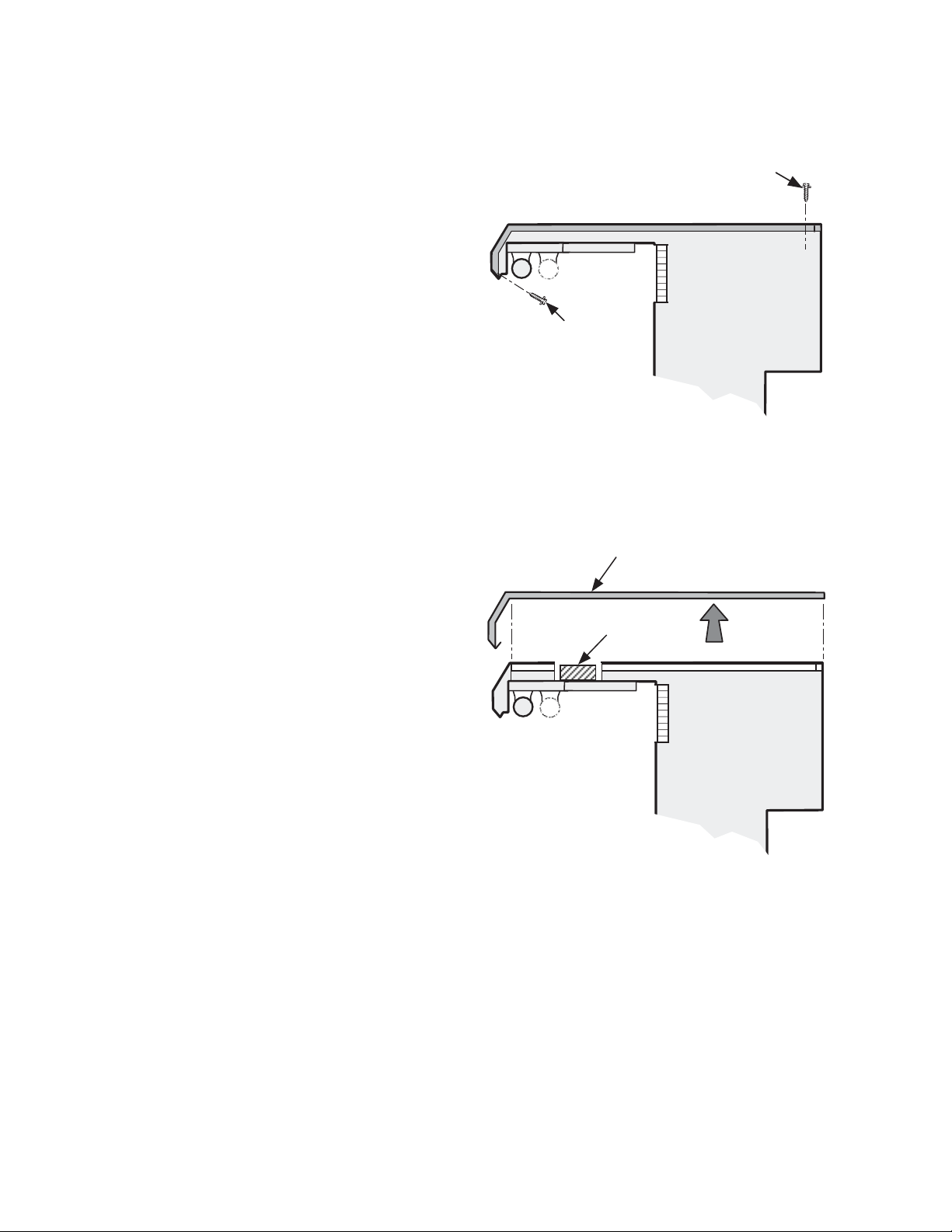
The ballast for the canopy and shelf lamps is
located behind the canopy on the left-hand end of
the merchandiser (when facing case).
To access the ballast:
1. Remove screws at bottom edge of the canopy
and rear of the top panel.
3. Remove the one piece canopy top panel by
moving panel forward slightly to clear flange
in front, then lifting up.
4. Service or replace ballast as required.
5. Reassemble items as they were originally
installed.
NOTE: Rail lamp ballast is located behind the
lower front panel.
REPLACING CANOPY AND SHELF LAMP BALLAST
Remove
Screws
Remove
Screws
Canopy Top Panel
Ballast
 Loading...