

Page 1

Please read the operator’s manual carefully and make sure you understand the instructions before using the machine.
Operator’s manual
GB 320
English
Page 2
-- 2 --
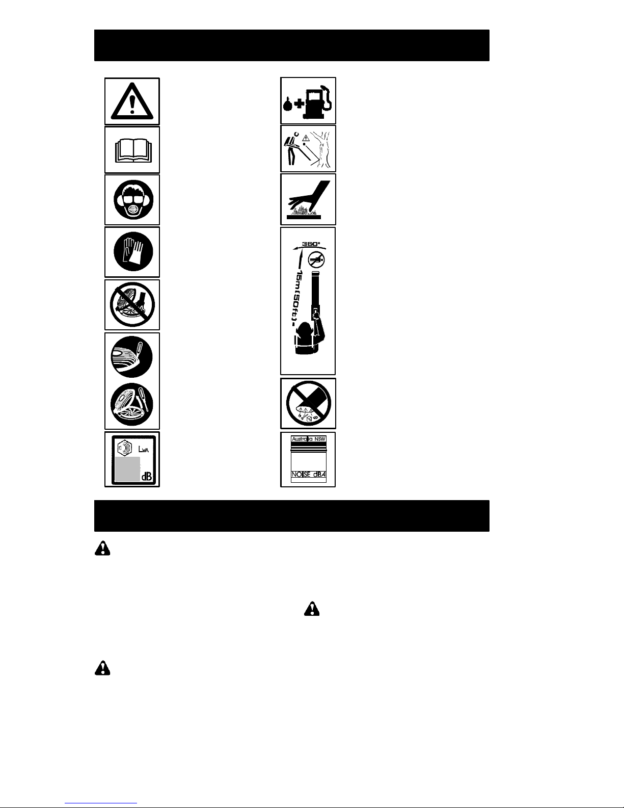
KEY TO SYMBOLS
Approved protective goggles
or visor, ear protection, and
face mask in dusty environments
must be worn.
The blower operator must make sure
that no bystanders or animals come
nearer than 15 metres.
Whenever several operators are
working in the same work area, they
should maintain a safe distance of at
least 15 meters f rom one another.
WARNI NG: The muffler is very
hot during and after use. Do not
touch the muffler, muffler guard, or
surrounding surfaces, or allow
combustible material such as dry
grassorfueltodoso.
Always wear approved,
protective gloves.
Instructions on how to open
vacuum inlet cover. Gently tilt
the handle of the screwdriver
toward the front of the unit to
releas e the latch while pulling
up on the vacuum inlet cover
with your other hand.
WARNING: This blower
can be dangerous! Careless
or improper use can
cause serious o r even fatal
injury.
Read and understand the
instruction manual before
using the blower.
WARNI NG: Be sure the
bottom cover is secured or
the vacuum tube is properly
installed. Avoid the impeller
blade with your hand or any
foreign object.
Sound power
level
Use unleaded or quality
leaded petrol and two
stroke oil.
WARNING: The blower may throw
objects at high velocity that can
ricochet and hit the operator. This
may cause serious eye damage.
Sound pressure level
at 7,5 metres
When using the vacuum attachment, the
unit is designed to pick up dry material
such as leaves, gras s, small twigs, and
bits of paper. Do not vacuum stones,
gravel, metal, broken glass, etc., to
avoid sev ere damage to the impeller.
SAFETY RULES
WARNING: Failure to follow all
Safety Rules and Precautions can result in
serious injury.
KNOW YOUR UNI T
S Read your instruction manual carefully until
you completely understand and can follow all
warnings and safety rules before operating
the unit.
D Restrict unit to users who understand and will
follow all warnings and safety rules in this
manual.
WARNING: Inspect area before start-
ing unit. Remove all debris and hard objects
such as rocks, glass, wire, etc. that can ricochet, be thrown, or otherwise cause injury or
damage during operation.
Use your unit as a blower for:
D Sweeping debris or grass clippings from
driveways, sidewalks, patios, etc.
D Blowing grass clippings, straw, or leaves into
piles, around joints, or between bricks.
PLAN AHEAD
WARNING: This machine produces
an electromagnetic field during operation. Under
some circumstances, this field may interfere
with active or passive medical implants. T o reduce the risk of serious or fatal injury, we recommend persons with medical implants to consult
their physician and the medical implant
manufacturer before operating this machine.
Page 3

-- 3 --
D Always wear eye and ear protection when op-
erating, servicing, or performing maintenance
on unit. Wearing eye protection will help to
prevent rocks or debris from being blown or
ricocheting into eyes and face which can result in blindness and/or serious injury. Eye
protection should be marked Z87.
D Always wear foot protection. Do not go bare-
foot or wear sandals.
D Always wear respirator or face mask when
working with unit in dusty environments.
D Secure hair above shoulder length. Secure or
remove jewelry, loose clothing, or clothing
with loosely hanging straps, ties, tassels, etc.
They can be caught in moving parts.
D Do not operate unit when you are tired, ill, up-
set, or if you are under the influence of alcohol, drugs, or medication.
D Keep children, bystanders, and animals away
from work area a minimum of 15 meters when
starting or operating unit. Do not point blower
nozzle in the direction of people or pets.
FUEL SAFETY
D Eliminate all sources of sparks or flame (in-
cluding smoking, open flames, or work that
can cause sparks) in the areas where fuel is
mixed, poured, or stored.
D Mix and pour fuel in an outdoor area; store
fuel in a cool, dry, well ventilated place; use an
approved, marked container for all fuel purposes.
D Do not smoke while handling fuel or while op-
erating the unit.
D Make sure the unit is properly assembled and
in good operating condition.
D Do not fill fuel tank while engine is hot or run-
ning.
D Avoid spilling fuel or oil. Wipe up fuel spills be-
fore starting engine.
D Move at least 3 meters away from fuel and fu-
eling site before starting engine.
D Always store petrol in a container approved
for flammable liquids.
OPERATE YOUR UNIT SAFELY
WARNING: Stop the engine before
opening the vacuum inlet door. The engine
must be stopped and the impeller blades no
longer turning to avoid serious injury from the
rotating blades.
D This garden blower is only designed for blow-
ing away leaves and other debris on the
ground.
D Inspect unit before each use for worn, loose,
missing, or damaged parts. Do not use until
unit is in proper working order.
D Keep outside surfaces free of oil and fuel.
D Never start or run engine inside a closed
room or building. Breathing exhaust fumes
can kill.
D Mufflers fitted with catalytic converters get
very hot during use and remain so for some
time after stopping. This also applies at idle
speed. Contact can result in burns to the skin.
Remember the risk of fire!
D T o avoid static electricity shock, do not wear
rubber gloves or any other insulated gloves
while operating unit.
D Do not set unit on any surface except a clean,
hard area while engine is running. Debris
such as gravel, sand, dust, grass, etc. could
be picked up by the air intake and thrown out
through discharge opening, damaging unit,
property, or causing serious injury to bystanders or operator.
D Avoid dangerous environments. Do not use in
unventilated areas or where explosive vapors
or carbon monoxide build up could be present.
D Do not overreach or use from unstable sur-
faces such as ladders, trees, steep slopes,
rooftops, etc. Keep firm footing and balance at
all times.
D Never place objects inside the blower tubes;
always direct the blowing debris away from
people, animals, glass, and solid objects such
as trees, automobiles, walls, etc. The force of
air can cause rocks, dirt, or sticks to be
thrown or to ricochet which can hurt people or
animals, break glass, or cause other damage.
D Never run unit without the proper equipment
attached. When using your unit as a blower,
always install blower tubes.
D Check air intake opening and blower tubes
frequently, always with engine stopped and
spark plug disconnected. Keep vents and discharge tubes free of debris which can accumulate and restrict proper air flow.
D Never place any object in the air intake open-
ing as this could restrict proper air flow and
cause damage to the unit.
D Never use for spreading chemicals, fertilizers,
or other substances which may contain toxic
materials.
D T o avoid spreading fire, do not use near leaf or
brush fires, fireplaces, barbecue pits, ashtrays, etc.
D Use only for jobs explained in this manual.
MAINTAIN YOUR UNIT PROPERLY
D Have all maintenance other than the recom-
mended procedures described in the instruction manual performed by an authorized service dealer.
D Disconnect spark plug before performing
maintenance except for carburetor adjustments.
D Use only recommended McCulloch replace-
ment parts; use of any other parts may void
your warranty and cause damage to your unit.
D Empty fuel tank before storing the unit. Use
up fuel left in carburetor by starting engine and
letting it run until it stops.
D Do not use any accessory or attachment
other than those recommended by manufacturer for use with your unit.
D Do not store the unit or fuel in a closed area
where fuel vapors can reach sparks or an
open flame from hot water heaters, electric
moto r s or switches, furna ce s, etc.
D Store in a dry area out of reach of children.
D Secure the machine during transport.
SAFETY NOTICE: Exposure to vibrations
through prolonged use of gasoline powered
hand tools could cause blood vessel or nerve
damage in the fingers, hands, and joints of people prone to circulation disorders or abnormal
Page 4
-- 4 --
swelling. Prolonged use in cold weather has
been linked to blood vessel damage in otherwise healthy people. If symptoms occur such as
numbness, pain, loss of strength, change in skin
color or texture, or loss of feeling in the fingers,
hands, or joints, discontinue the use of this tool
and seek medical attention. An antivibration
system does not guarantee the avoidance of
these problems. Users who operate power tools
on a continual and regular basis must monitor
closely their physical condition and the condition
of this tool.
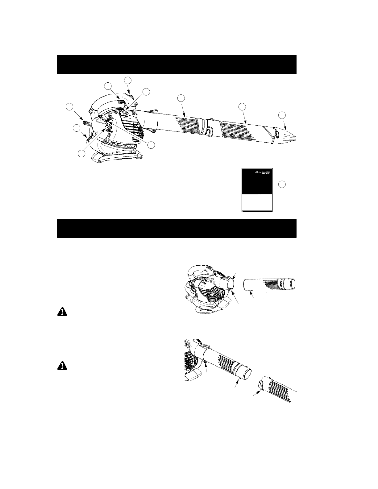
WHAT IS WHAT?
1. Throttle trigger 7. Spark plug
2. STOP switch 8. Upper blower tube
3. Primer button 9. Lower blower tube
4. Choke lever 10. High--speed nozzle
5. Fuel cap 11. Instruction manual
6. Starter rope
WHAT IS WHAT?
6
1
2
7
8
9
10
4
3
5
11
ASSEMBLY
CARTON CONTENTS
Check carton contents against the following list.
S Blower
S Upper blower tube
S Lower blower tube
S High velocity nozzle
NOTE: It is normal for the fuel filter to rattle
in the empty fuel tank.
ASSEMBLY
WARNING: Stop engine and be sure
the impeller blades have stopped turning before opening the vacuum inlet door or attempting to insert or remove the vacuum or
blower tubes. The rotating blades can cause
serious injury. Always disconnect the spark
plug before performing maintenance or accessing movable parts.
WARNING: If received assembled,
repeat all steps to ensure your unit is properly
assembled and all fasteners are secure. Follow all safety information in the manual andon
the unit.
D A standard screwdriver is required for as-
sembly.
BLOWER TUBE ASSEMBLY
1. Align the rib on the upper blower tube with
the groove in the blower outlet; slide the
tube into place.
NOTE: The tube clamp bolt must be loose
enough to allow blower tube to be inserted in
blower outlet. Loosen the bolt by turning counterclockwise (do not remove nuts).
Blower Outlet
Rib
Groove
2. Secure the tube by turning the bolt clockwise.
3. Align the slots on the lower blower tube
with the tabs on the upper blower tube.
Upper Blower
Tube
Ta b
Slot
Lower Blower
Tube
Tube
clamp
bolt and
nut
4. Slide the lower blower tube onto the upper
blower tube.
5. Turn the lower blower tube clockwise until
a click is felt to secure the lower blower
tube to the upper blower tube.
Page 5

-- 5 --
NOTE: When the upper and lower blower
tubes are assembled together properly, the
arrows on both tubes will be aligned.
6. Toremove the tubes, turn the bolt counterclockwise to loosen the tubes (do not remove nuts ); remove the tubes.
HIGH-- SPEED NOZZLE ASSEMBLY
When greater air speed is desired, use the
high-- speed nozzle.
1. Align the slots on the nozzle with the tabs
on the lower blower tube.
High--Speed
Nozzle
Ta b
Slot
Lower Blower
Tube
2. Slide the nozzle onto the lower blower tube.
3. Turn the nozzle clockwise until a click is
felt to secure the nozzle to the lower blower tube.
OPERATION
OPERATING POSITION
Hearing Protection
Eye
Protection
OPERATING TIPS
S While blowing debris, hold the unit with the
muffler side facing away from your body
and clothes (see OPERATING POSITION).
S To reduce the risk of hearing loss
associated with sound level(s), hearing
protection is required.
S To reduce the risk of injury associated with
contacting rotating parts, stop the engine before installing or removing attachments. Do
not operate without guard(s) in place.
S Operate power equipment only at reasonable
hours-- not early in the morning or late at night
when people might be disturbed. Comply with
times listed in local ordinances. Usual recommendations are 9:00 a.m. to 5:00 p.m.,
Monday though Saturday.
S To reduce noise levels, limit the number of
pieces of equipment used at any one time.
S To reduce noise levels, operate power
blowers at the lowest possible throttle
speed to do the job.
S Use rakes and brooms to loosen debris be-
fore blowing.
S In dusty conditions, slightly dampen sur-
faces or use a mister attachment when water is available.
S Conserve water by using power blowers
instead of hoses for many lawn and garden
applications, including areas such as gutters,
screens, patios, grills, porches, and gardens.
S Watch out for children, pets, open windows,
or freshly washed cars. Blow debris away
safely.
S Use the full blower nozzle extension so the
air stream can work close to the ground.
S After using blowers and other equipment,
CLEAN UP! Dispose of debris in trash receptacles.
BEFORE STARTING ENGINE
WARNING: Be sure to read the fuel
information in the safety rules before you
begin. If you do not understand the safety
rules, do not attempt to fuel your unit. Contact
an authorized service dealer.
FUELING ENGINE
WARNING: Remove fuel cap slowly
when refueling.
This engine is certified to operate on unleaded
petrol. Before operation, petrol must be mixed
with a good quality 2--cycle air--cooled engine oil
designed to be mixed at a ratio of 40:1. A 40:1
ratio is obtained by mixing 5 liters of unleaded
petrol with 0,125 liter of oil. DO NOT USE
automotive oil or marine oil. These oils will
cause engine damage. When mixing fuel, follow
instructions printed on oil container . Once oil is
added to petrol, shake container momentarily to
assure that the fuel is thoroughly mixed. Always
read and follow the safety rules relating to fuel
before fueling your unit.
MIXING RATIO
Petrol -- Litre Two--Stroke Oil -- ml
40:1 (2.5%)
250
5 125
10 250
CAUTION: Never use straight petrol in your
unit. This will cause permanent engine damage.
FUEL REQUIREMENTS
Use good quality unleaded petrol. The lowest
recommended octane grade is 90 (RON).
Page 6
-- 6 --
IMPORTANT
Use of alcohol blended fuels (more than 10%
alcohol) can cause major engine performance
and durability problems.
WARNING: Incorrect use of fuel and/
or lubricants will c aus e problems s uc h as:
improper c lutc h engagements, ov erheating, vapor loc k , power loss, lubrication deficiency, deterioration of fuel lines, gaskets
and internal carburetor c omponents, etc.
Alcohol blended fuels will cause a high absorption of moisture in the fuel/oil mix ture,
causing the s eparation of oil and fuel.
HOW TO STOP Y OUR ENGINE
S Release the throttle trigger.
S Push and hold the STOP switch in the
STOP position until the engine stops.
BEFORE STARTING THE ENGINE
WARNING: YouMUSTmakesurethe
tubes are secure before using the unit.
D Fuel engine. Move at least 3 meters away
from the fueling site.
D Hold the unit in the starting position as
shown. Make sure the blower end is directed away from people, animals, glass,
and solid objects.
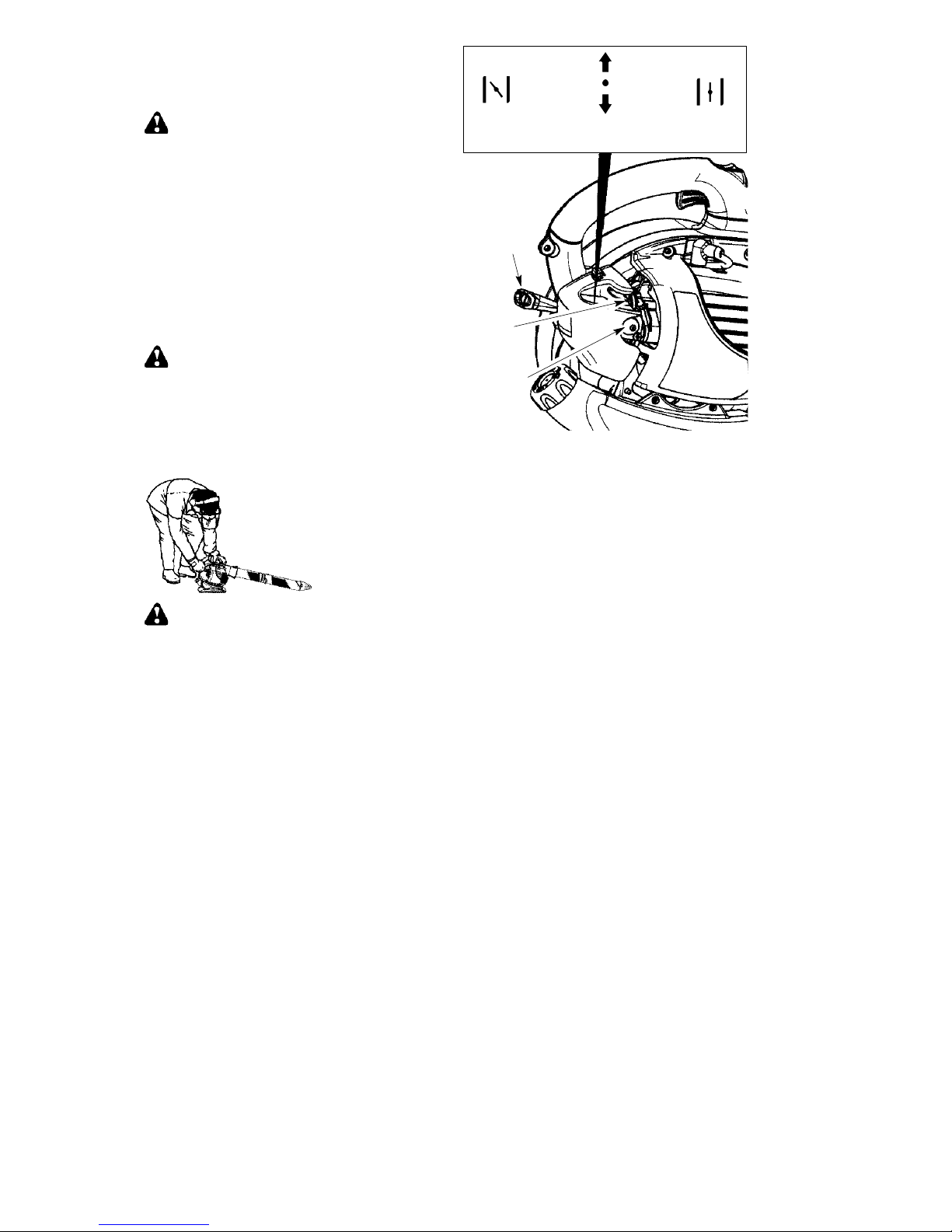
STARTING POSITION
WARNING: When starting engine,
hold the unit as illustrated. Do not set unit on
any surface except a clean, hard area when
starting engine or while engine is running. Debris such as gravel, sand, dust, grass, etc.
could be picked up by the air intake and
thrown out through the discharge opening,
damaging theunit or property, or causing serious injury to bystanders or the operator.
ST AR TI NG A COLD ENGINE (or a
warm engine after running out of fuel)
1. Slowly press the primer bulb 6 times.
2. Move choke lever to the FULL CHOKE position.
3. Squeeze the throttle trigger fully and hold
through all remaining steps.
Choke
Lever
Starter
Handle
Primer
Bulb
HALF
CHOKE
FULL
CHOKE
OFF
CHOKE
4. Pull starter rope handle sharply until engine
sounds as if it is trying to start, but do not pull
rope more than 4 times.
5. As soon as engine sounds as if it is trying to
start, move choke lever to HALF CHOKE
position.
6. Pull starter rope sharply until engine runs,
but no more than 6 pulls.
NOTE: If the en-
gine doesn’t start after 6 pulls (at the HALF
CHOKE position), move the choke lever to
the FULL CHOKE position and press the
primer bulb 6 times. Squeeze and hold the
throttle trigger and pull the starter rope 2
more times. Move the choke lever to the
HALF CHOKE position and pull the starter
rope until the engine runs, but no more
than 6 pulls. If the engine still doesn’t start,
it is probably flooded. Proceed to STARTING A FLOODED ENGINE.
7. Once the engine starts, allow it to run 10 seconds, then move the choke lever to the
RUN position. Allow the unit to run for 30
more seconds at RUN before releasing the
throttle trigger.
NOTE: If engine dies with
the choke lever in the RUN position, move
the choke lever to the HALF CHOKE position and pull the rope until engine runs, but
no more than 6 pulls.
Page 7
-- 7 --
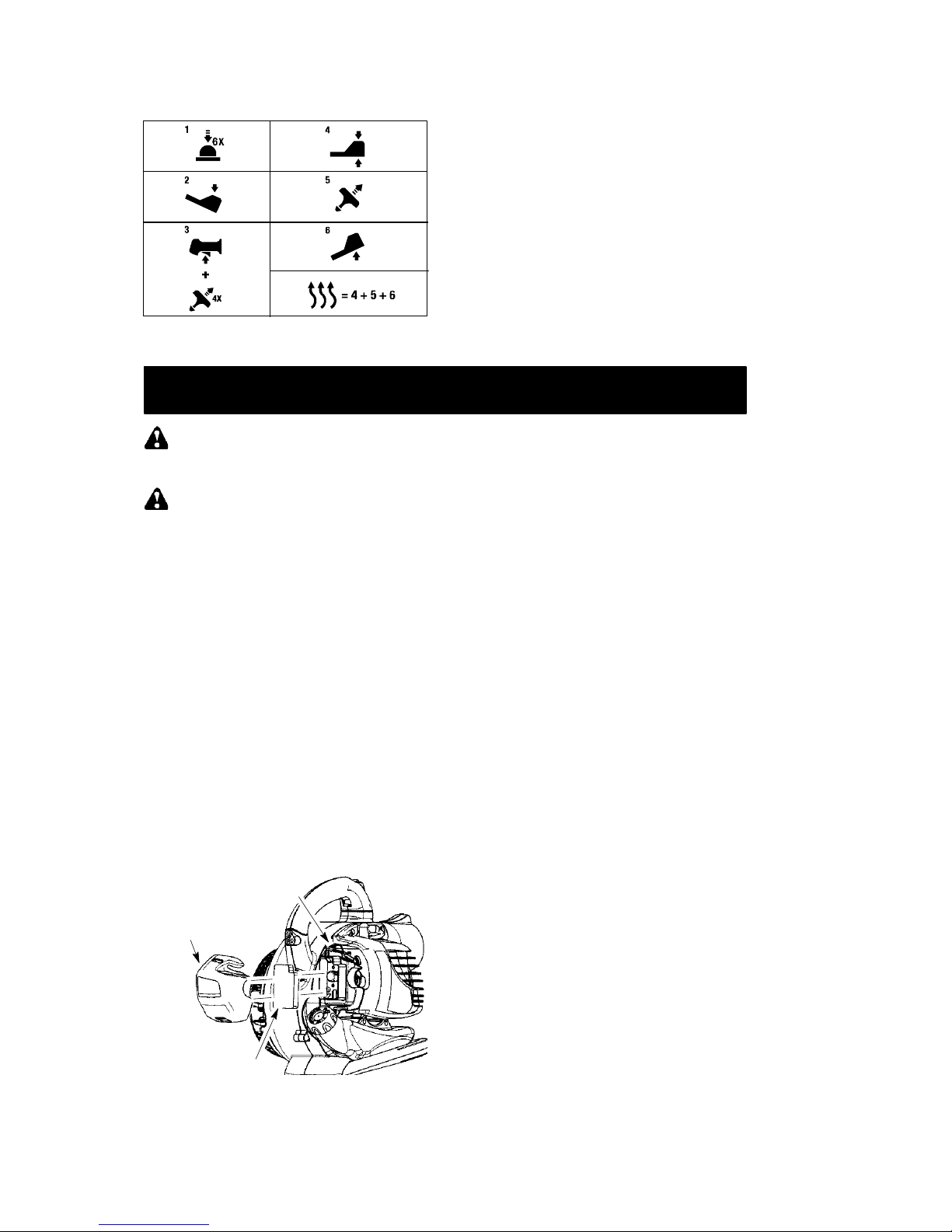
There is a simplified start reminder (with
illustrations to describe each step) located on the back of the blower.
STARTING A WARM ENGINE
1. Move the choke lever to the HALF CHOKE
position.
2. Squeeze the throttle trigger fully and hold
through all remaining steps.
3. Pull starter rope sharply until engine runs,
but no more than 6 pulls.
4. Allow engine to run 15 seconds, then move
the choke lever to RUN.
NOTE: If engine has not started, pull starter
rope 5 more pulls. If engine still does not run, it
is probably flooded.
STARTING A FLOODED ENGINE
Flooded engines can be started by placing the
choke lever in the RUN position; then, pull the
rope to clear the engine of excess fuel. This
could require pulling the starter handle many
times depending on how badly the unit is
flooded. If the unit still doesn’t start, refer to
TROUBLESHOOTING TABLE.
MAINTENANCE
WARNING: Avoid touching muffler
unless engine and muffler are cold. A hot
muffler can cause serious burns.
WARNING: Disconnect the spark
plug before performing maintenance except
for carburetor adjustments.
CHECK FOR LOOSE
FASTENERS A ND PARTS
S Muffler
S Spark Plug Boot
S Air Filter
S Housing Screws
CHECK FOR DAMAGED OR
WORN PARTS
Contact an authorized service dealer for replacement of damaged or worn parts.
S Fuel Tank. Discontinue use of unit if fuel
tank is damaged or leaks.
S Vacuum Bag -- Discontinue use of vacuum
bag if it is torn or damaged.
INSPECT AND CLEAN UNIT & LABELS
S After each use, inspect complete unit for
loose or damaged parts. Clean the unit and
decals using a damp cloth with a mild detergent.
S Wipe off unit with a clean dry cloth.
CLEAN AIR FILTER
Air Filter
Cover
A
ir Filter
Button
A dirty air filter decreases engine performance and increases fuel consumption and
harmful emissions. Always clean after every
5 hours of operation or yearly, whichever
comes first.
1. Clean the cover and the area around it to
keep debris from falling into the carburetor
chamber when the cover is removed.
NOTE: Move choke lever to RUN position
before opening air filter cover.
2. Remove parts as illustrated.
NOTE: Do not clean filter in gasoline or
other flammable solvent. Doing so can
create a fire hazard or produce harmful
evaporative emissions.
3. Wash the filter in soap and water.
4. Allow filter to dry.
5. Apply a few drops of oil to the filter;
squeeze filter to distribute oil.
6. Replace parts.
REPLACE SPARK PLUG
Replace spark plug each year to ensure the
engine starts easier and runs better. Set
spark plug gap at 0.6 mm. Ignition timing is
fixed, nonadjustable.
1. Twist, then pull off spark plug boot.
2. Remove spark plug from cylinder and discard.
3. Replace with Champion RCJ-6Y spark
plug and tighten securely with a 19 mm
socket wrench.
4. Reinstall the spark plug boot.
REPLACE FUEL FILTER
T o replace fuel filter, drain unit by running it dry of
fuel, then remove fuel cap/retainer assembly
from tank. Pull filter from tank and remove it from
fuel line. Install new fuel filter on fuel line; reinstall
parts.
Page 8
-- 8 --
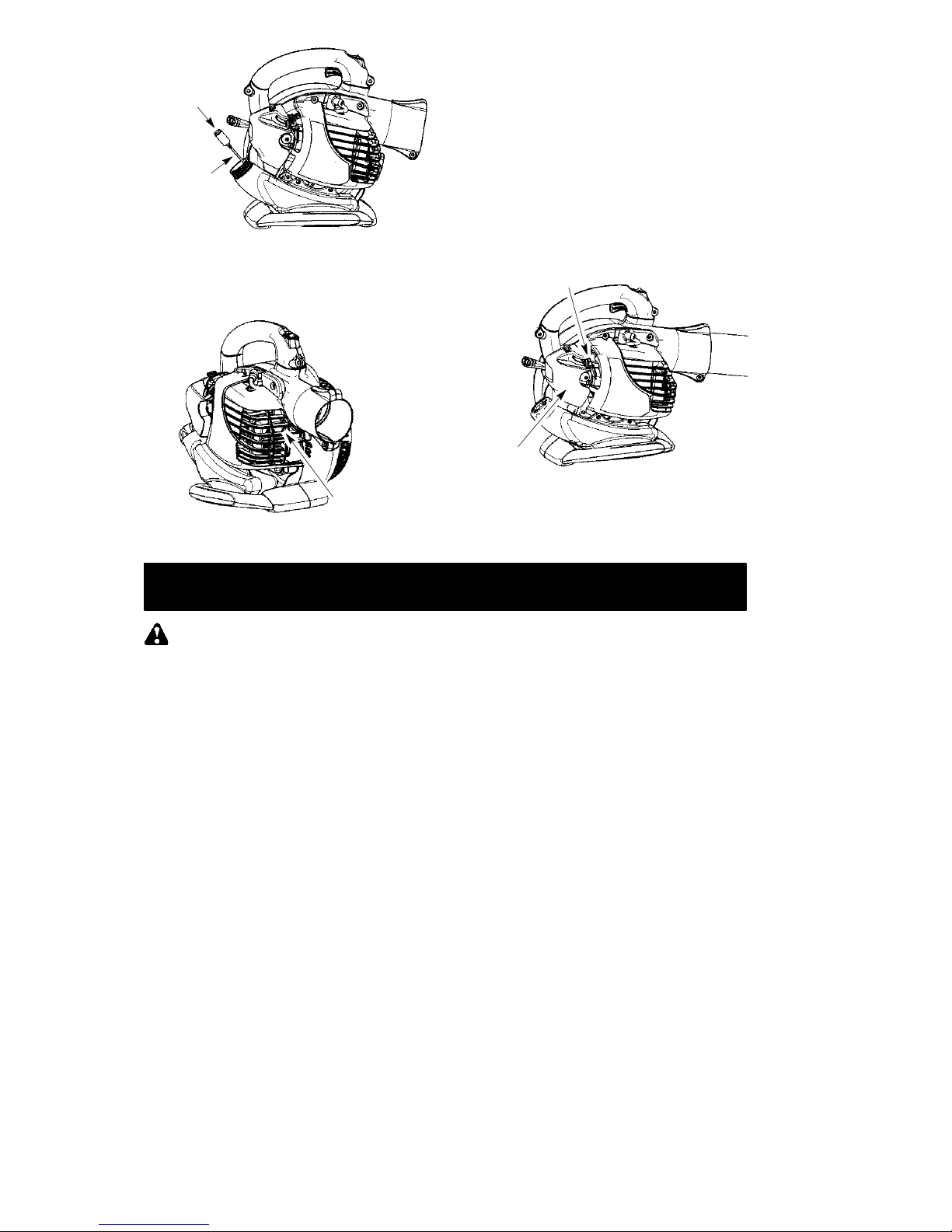
Fuel Line
Fuel Filter
CHECK MUFFLER MOUNTING
SCREWS
Once each year, ensure muffler mounting
screws are secure and tightened properly to
prevent damage.
Muffler
Mounting
Screw
CARBURETOR ADJUSTMENTS
The carburetor has been carefully set at the
factory. Adjustments may be necessary if you
notice any of the following conditions:
S Engine will not idle when the throttle is re-
leased.
Idle Speed Adjustment
Allow engine to idle. Adjust speed until engine
runs without stalling (idle speed too slow).
S Turn idle speed screw clockwise to in-
crease engine speed if engine stalls or dies.
S Turn idle speed screw counterclockwise to
decrease engine speed.
Air
Filter
Cover
Idle Speed Screw
If you require further assistance or are unsure
about performing this procedure, contact an
authorized service dealer.
STORAGE
WARNING: Prepare unit for storage at
end of season or if it will not be used for 30 days
or more.
S Allow engine to cool, and secure the unit be-
fore storing or transporting.
S Store unit and fuel in a well ventilated area
where fuel vapors cannot reach sparks or
open flames from water heaters, electric motors or switches, furnaces, etc.
S Store unit with all guards in place. Position unit
so that any sharp object cannot accidentally
cause injury.
S Store unit and fuel well out of the reach of chil-
dren.
EXTERNAL SURFACES
S If your unit is to be stored for a period of time,
clean it thoroughly before storage. Store in a
clean dry area.
S Lightly oil external metal surfaces.
INTERNAL ENGINE
S Remove spark plug and pour 1 teaspoon of
2-cycle engine oil (air cooled) through the
spark plug opening. Slowly pull the starter
rope 8 to 10 times to distribute oil.
S Replace spark plug with new one of recom-
mended type and heat range.
S Clean air filter.
S Check entire unit for loose screws, nuts, and
bolts. Replace any damaged, broken, or worn
parts.
S Start each season using only fresh fuel hav-
ing the proper gasoline to oil ratio.
OTHER
S Do not store gasoline from one season to
another.
S Replace your gasoline can if it starts to rust.
Page 9
-- 9 --
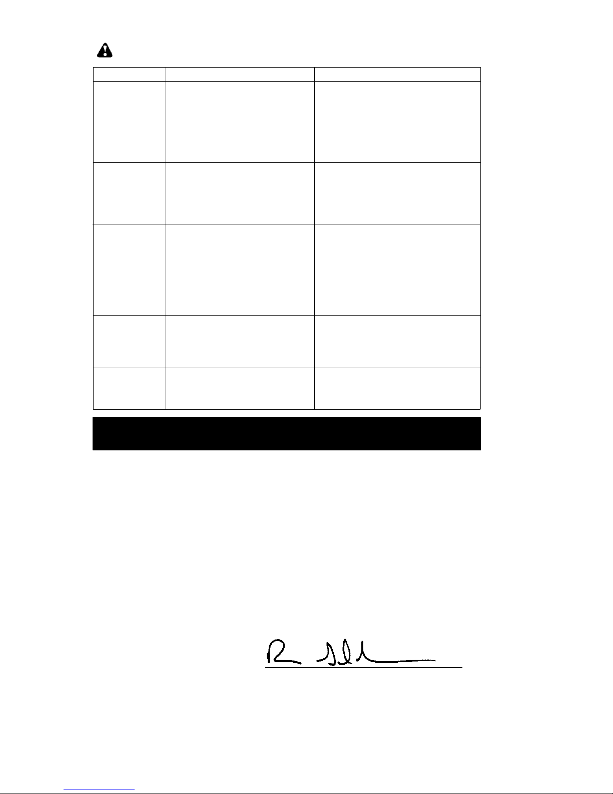
1.See “Fueling Your Unit.”
2.Replace with correct spark plug.
3. Contact an authorized service dealer.
4. Contact an authorized service dealer.
TROUBLE CAUSE REMEDY
Engine will not
start.
1.Engine flooded.
2.Fuel tank empty.
3.Spark plug not firing.
4.Fuel not reaching carburetor.
5.Compression low.
1.Set unit aside for 10-15 minutes to
allow fuel to vaporize.
2.Fill tank with correct fuel mixture.
3.Install new spark plug.
4.Check for dirty fuel filter; replace.
Check for kinked or split fuel line;
repair or replace.
5. Contact an authorized service dealer.
Engine will not
idle properly.
1.Fuel not reaching carburetor.
2.Carburetor requires adjustment.
3.Crankshaft seals worn.
4.Compression low.
1.Check for dirty fuel filter; replace.
Check for kinked or split fuel line;
repair or replace.
2. Contact an authorized service dealer.
3. Contact an authorized service dealer.
4. Contact an authorized service dealer.
1.Air filter dirty.
2.Fuel not reaching carburetor.
3.Spark plug fouled.
4.Spark arresting screen clogged.
5.Carburetor requires adjustment.
6.Carbon build up.
7.Compression low.
Engine will not
accelerate,
lacks power, or
dies under a
load.
1.Clean or replace air filter.
2.Check for dirty fuel filter; replace.
Check for kinked or split fuel line;
repair or replace.
3.Clean or replace spark plug; re-gap.
4.Replace screen.
5. Contact an authorized service dealer.
6. Contact an authorized service dealer.
7. Contact an authorized service dealer.
Engine
smokes
excessively.
1.Choke partially on.
2.Fuel mixture incorrect.
3.Air filter dirty.
4.Carburetor requires adjustment.
1.Adjust choke.
2.Empty fuel tank and refill with
correct fuel mixture.
3.Clean or replace air filter.
4. Contact an authorized service dealer.
Engine
runs hot.
1.Fuel mixture incorrect.
2.Spark plug incorrect.
3.Carburetor requires adjustment.
4.Carbon build up.
TROUBLESHOOTING TABLE
WARNING: Always stop unit and disconnect spark plug before performing any of the
recommended remedies below other than remedies that require operation of the unit.
DECLARATION OF CONFORMITY
EC Declaration of Conformity (Only applies to Europe)
We, Husqvarna AB, SE-561 82 Huskvarna, Sweden, tel: +46-- 36--146500, as authorised
representative in the Community, declare that the garden blower model McCulloch GB 320
with serial numbers dating from 2012 and onwards (the year is clearly stated on the rating
plate, followed by the serial number), comply with the requirements of the COUNCIL’S
DIRECTIVES:
of 17 May 2006 “relating to machinery” 2006/42/EC;
of 15 December 2004 “relating to electromagnetic compatibility” 2004/108/EC, and applicable
supplements; and
of 8 May 2000 “relating to the noise emissions in the environment” in accordance with Annex
Vof2000/14/EC. For information relating to noise emissions, see T echnical data section.
The following standards have been applied: EN ISO 12100-1/A1:2009, EN ISO
12100-2/A1:2009, CISPR 12:2007.
SMP Svensk Maskinprovning AB, Fyrisborgsgatan 3, S-- 754 50 Uppsala, Sweden, has
performed voluntary type examination on behalf of Husqvarna AB. The certificate(s) are
numbered: SEC/09/2024.
1 2 -- 0 4 -- 3 0
Ronnie E. Goldman, Director of Engineering
Authorized representative for Husqvarna AB and
responsible for technical documentation
Page 10

-- 1 0 --
TECHNICAL DATA
MODEL: GB 320
ENGINE
Cylinder displacement, cm
3
25
Maximum Engine Power, according to ISO 8893, kW 0,75
Idle Speed +/-- 400, rpm 3700
IGNITION SYSTEM
Spark plug Champion RCJ-- 6Y
Electrode gap, mm 0,6
FUEL AND LIBRICATION SYSTEM
Fuel tank capacity, cm
3
540
WEIGHT
Weight without fuel and tubes, kg 4,25
NOISE EMISSIONS
(see Note 1)
Sound power level, measured dB(A) 103,9
Sound power level, guaranteed L
WA
dB(A) 108,0
SOUND LEVELS
(see Note 2)
Equivalent sound pressure level at the operator’s ear, measured
according to ISO 22868, dB(A)
Equipped with blower tubes and nozzle (original) 96,7
VIBRATION LEVELS
(see Note 3)
Equivalent vibration levels (a
hv,eq
) at handles, measured
according to ISO 22867, m/s
2
Equipped with blower tubes and nozzle (original), right 10,1
Note 1: Noise emissions in the environment measured as sound power (L
WA
) in conformity with
EC directive 2000/14/EC. Reported sound power level for the machine has been measured with
the original cutting attachment that gives the highest level. The difference between guaranteed
and measured sound power is that the guaranteed sound power also includes dispersion in the
measurement result and the variations between different machines of the same model according
to Directive 2000/14/EC.
Note 2: Reported data for equivalent sound pressure level for the machine has a typical
statistical dispersion (standard deviation) of 1 dB(A).
Note 3: Reported data for equivalent vibration level has a typical statistical dispersion (standard deviation) of 1 m/s
2
.
Page 11

-- 11 --
STATEMENT OF WARRANTY
Husqvarna Outdoor Products provides warranty to the initial purchaser for all products
that are sold by an authorised Husqvarna
Outdoor Products Dealer.
The warranty provides the purchaser with a
guarantee against faulty workmanship in
manufacture and/or defective components. If
any product supplied by Husqvarna Outdoor
Products is found to be defective due to faulty
manufacture within the warranty period,
Husqvarna Outdoor Products through its Authorised Servicing Dealers will effect the repair or replacement at their discretion to the
customer, free of charge providing:
S The fault is reported directly to the Autho-
rised Servicing Dealer.
S Proof of purchase is provided.
S The fault is not caused by misuse, neglect
or faulty adjustment by the user.
S The failure has not occurred through nor-
mal wear and tear.
S The product has not been serviced, re-
paired or alterations made by any person
not authorised by Husqvarna Outdoor
Products.
S The machine has not been used for hire.
Nothing contained in this warranty is intended
to purport to restrict, modify or exclude the operation of any legislation in the State where
the product was purchased.The following
items are not covered by this warranty:
S Normal customer maintenance items
which become worn through normal regular
use, including, but not limited to, belts,
blades, blade adapters, globes, filters,
guide bars, lubricants, rewind springs, saw
chain, spark plugs, starter ropes, and tines;
S Natural discolouration of material due to ul-
traviolet light;
S Engine and drive systems not manufac-
tured by Husqvarna Outdoor Products,
these items are covered by the respective
original equipment manufacturers warranty, all claims must be sent to the appropriate
manufacturer.
Product Warranty Period
Domestic Commercial
Non-- Powered Push Mowers 12 Months 90 Days
Electric and Petrol Walk--Behind Mowers 12 Months 90 Days
Electric and Petrol Chainsaws 12 Months 90 Days
Electric and Petrol Trimmers 12 Months 90 Days
Electric and Petrol Blowers 12 Months 90 Days
Petrol Ride--on Mowers 12 Months 90 Days
Page 12

Original instructionss
115490528 Rev. 1 6/15/12 BRW
 Loading...