

EN Operator's manual 2-9
ES-MX Manual del usuario 10-17
FR-CA Manuel d’utilisation 18-25
IT Manuale dell'operatore 26-33
ECA850, ESA850
Contents
1
4
10
11
12
5
2
3
6
7
9
ESA 850
5
3
2
1
4
7
6
8
ECA 850
Introduction..................................................................... 2
Safety..............................................................................3
Assembly........................................................................ 6
Introduction
Product description
We have a policy of continuous product development
and therefore reserve the right to modify the design and
appearance of the products without prior notice.
Intended use
WARNING: Use this attachment only with
products that it is intended for. Refer to the
accessory chapter in the operator's manual
of your product.
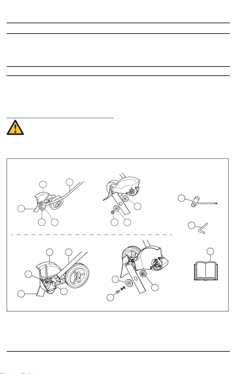
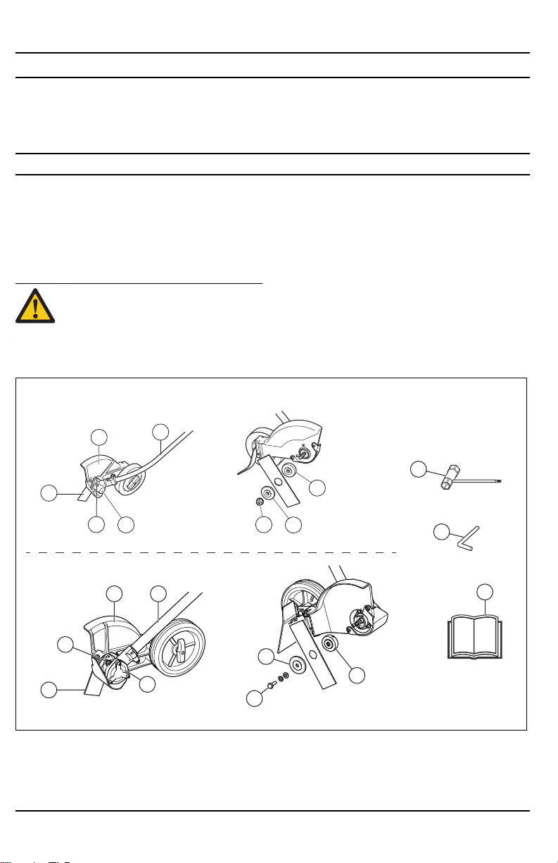
Attachment overview
Maintenance................................................................... 8
Technical data................................................................ 9
Use the attachment for edging lawns only.
1. Blade
2. Grease filler cap, bevel gear
3. Bevel gear
4. Cutting attachment guard
5. Shaft
2 878 - 001 - 23.10.2018
6. Drive disc
7. Support flange
8. Locknut
9. Blade mounting bolt
10. Combination wrench
11. Locking pin
WARNING
The engine exhaust from this product
contains chemicals known to the State of
California to cause cancer, birth defects
or other reproductive harm.
12. Operator′s manual
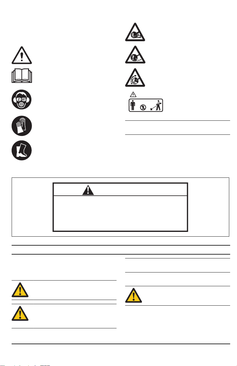
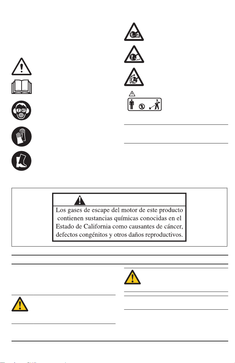
Symbols on the cutting attachment
Careless or incorrect use of this attachment
can result in serious or fatal injury to the
operator or others.
Please read the operator’s manual carefully
and make sure you understand the
instructions before using the attachment.
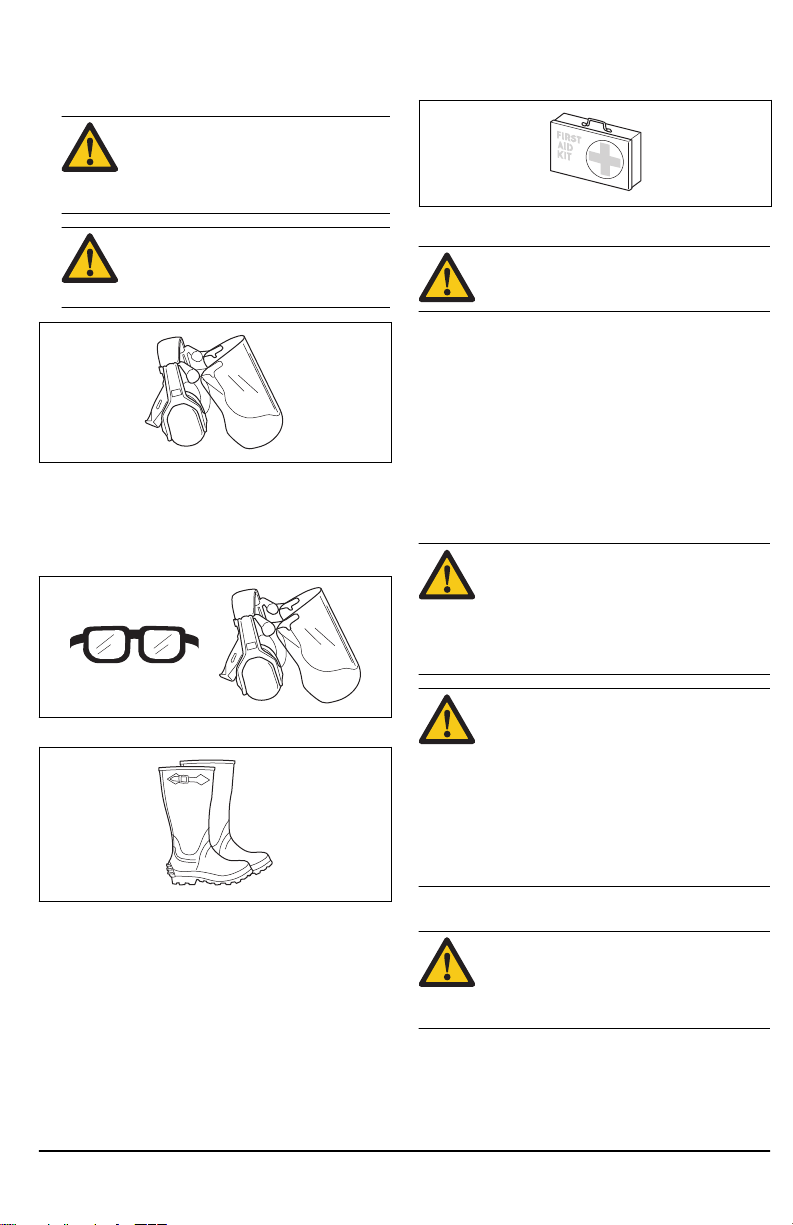
Always wear approved hearing protection
and protective goggles or a visor. A
breathing mask should be used when there
is a risk of dust.
Always wear approved protective gloves.
Wear sturdy, non-slip boots.
Proposition 65
Rotating blade. Keep hands and feet clear.
The arrow indicates the direction of rotation.
Watch out for thrown objects and ricochets.
The blade continues to rotate even after the
engine has stopped.
The operator of the attachment
must ensure, while working, that
no persons or animals come
closer than 15 meters / 50 ft.
Note: Other symbols/decals on the attachment refer to
special certification requirements for certain markets.
Safety
Safety definitions
Warnings, cautions and notes are used to point out
specially important parts of the manual.
WARNING: Used if there is a risk of injury or
death for the operator or bystanders if the
instructions in the manual are not obeyed.
CAUTION: Used if there is a risk of damage
to the product, other materials or the
adjacent area if the instructions in the
manual are not obeyed.
Note: Used to give more information that is necessary in
a given situation.
General safety instructions
WARNING: Read the safety instructions that
follows before you use the attachment.
• Please read the operator’s manual carefully and
make sure you understand the instructions before
using the attachment.
878 - 001 - 23.10.2018 3
• These instructions supplement the instructions that
were included with the product. For other
procedures, please refer to the operating instructions
for the product.
• Under no circumstances may the design of the
attachment be modified without the permission of the
manufacturer. Do not use an attachment that
appears to have been modified by others and always
use original accessories. Non-authorized
modifications and/or accessories can result in
serious personal injury or the death of the operator
or others.
Safety instructions for operation
WARNING: Read the saftey instructions that
follow before you use the product.
• Never allow children to use the product.
• Never allow anyone else to use the product without
first ensuring that they have understood the contents
of the operator’s manual.
• Keep unauthorized persons at a distance. Children,
animals, onlookers and helpers should be kept
outside the safety zone of 15 m (50 ft) while you
work. Stop the product immediately if anyone
approaches.
• Make sure you can move and stand safely. Check
the area around you for possible obstacles (roots,
rocks, branches, ditches, etc.) in case you have to
move suddenly. Take great care when working on
sloping ground.
• Inspect the working area. Remove all loose objects,
such as stones, broken glass, nails, steel wire,
string, etc. that could be thrown out or become
wrapped around the cutter or cutter guard.
• Watch out for thrown objects. Always wear approved
eye protection. Never lean over the cutting
attachment guard. Stones, rubbish, etc. can be
thrown up into the eyes causing blindness or serious
injury.
• Do not use the product in bad weather, such as
dense fog, heavy rain, strong wind, intense cold, etc.
• Do not use the product unless you are able to call for
help in the event of an accident.
• The engine must be switched off before moving.
• Never put the product down with the engine running
unless you have it in clear sight.
• Always use both hands to hold the product. Hold the
product at the side of your body.
• Use your right hand to control the throttle setting.
• Listen out for warning signals or shouts when you
are wearing hearing protection. Always remove your
hearing protection as soon as the engine stops.
• Make sure that your hands and feet do not come
near the cutting attachment when the engine is
running.
• When the engine is switched off, keep your hands
and feet away from the cutting attachment until it has
stopped completely.
• Always keep the cutter close to the ground.
• Always carry out edging at full throttle.
• Always slow the engine to idle speed after each
working operation. Long periods at full throttle
without any load on the engine (i.e without the
resistance that the cutting attachment exerts on the
engine when you are using the product) can lead to
serious engine damage.
• Be especially careful when pulling the edger towards
you during work.
• If any foreign object is hit or if vibrations occur stop
the product immediately. Disconnect the HT lead
from the spark plug. Check that the product is not
damaged. Repair any damage.
• Sometimes grass or stones can get trapped in the
cutter guard and cutter. Always stop the engine
before cleaning.
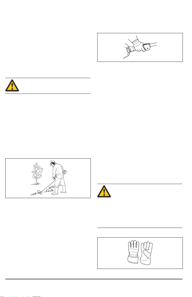
Personal protective equipment
WARNING:
personal protective equipment whenever
you use the procuct. Personal protective
equipment cannot eliminate the risk of injury
but it will reduce the degree of injury if an
accident does happen. Ask your dealer for
help in choosing the right equipment. Please
read the operator’s manual carefully and
make sure you understand the instructions
before using the procuct.
• Gloves should be worn when necessary.
You must use approved
4
878 - 001 - 23.10.2018
• Wear hearing protection that provides adequate
noise reduction.
WARNING: Listen out for warning
signals or shouts when you are wearing
hearing protection. Always remove your
hearing protection as soon as the engine
stops.
WARNING: Long-term exposure to
noise can result in permanent hearing
impairment. So always use approved
hearing protection.
• Always wear approved eye protection. If you use a
visor then you must also wear approved protective
goggles. Approved protective goggles must comply
with the ANSI Z87.1 standard in the USA or EN 166
in EU countries. Blows from branches or objects that
are thrown can damage the eyes.
• Always have a first aid kit nearby.
Safety devices on the attachment
WARNING: Read the warning instructions
that follow before you use the attachment.
In this section the attachment’s safety features, its
purpose and how checks and maintenance should be
carried out to ensure that it operates correctly. See
instructions under the heading
page 2
to find where these parts are located on your
attachment.
The life span of the attachment can be reduced and the
risk of accidents can increase if attachment
maintenance is not carried out correctly and if service
and/or repairs are not carried out professionally. If you
need further information please contact your nearest
servicing dealer.
WARNING: Never use a attachment with
defective safety components. The
attachment's safety equipment must be
inspected and maintained as described in
this section. If your attachment fails any of
these checks, contact your service agent to
get it repaired.
Attachment overview on
• Wear sturdy, non-slip boots.
• Always wear heavy, long pants, boots, gloves, and a
long-sleeve shirt. To reduce the risk of injury
associated with objects being drawn into rotating
parts, do not wear loose clothing, scarves, jewelry,
etc. Secure hair so it is above shoulder level.
• A breathing mask should be used when there is a
risk of dust.
878 - 001 - 23.10.2018
CAUTION: All servicing and repair work on
the product requires special training. This is
especially true of the product′s safety
equipment. If your product fails any of the
checks described below you must contact
your service agent. When you buy any of
our products we guarantee the availability of
professional repairs and service. If the
retailer who sells your product is not a
servicing dealer, ask him for the address of
your nearest service agent.
To check the cutting attachment guard
WARNING:
without an approved cutting attachment
guard. If an incorrect or faulty cutting
attachment guard is fitted this can cause
serious personal injury.
This cutting attachment guard is intended to prevent
loose objects from being thrown towards the operator.
The cutting attachment guard also protects the operator
from accidental contact with the blade.
Do not use a cutting attachment
5
• Check that the cutting attachment guard is not
damaged. Replace the cutting attachment guard if it
has been exposed to impact or is cracked.
• Only use original spare parts.
To check the blade
The blade is designed and manufactured to withstand
the loads that edging of a lawn involves.
• Check the blade for damage or cracks. A damaged
blade should always be replaced.
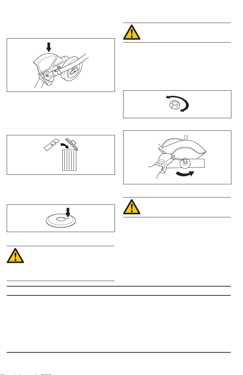
To check the support flange
• Check that the support flange is not cracked due to
fatigue or due to being tightened too much. Discard
the support flange if it is cracked.
CAUTION: The locknut has a left-hand
thread. To tighten the locknut to much can
cause damage to the threads.
The locknut secures the cutting attachment on the
output shaft. Protect your hand from injury when
assembling, use the cutting attachment guard as
protection when tightening with a socket wrench.
1. When fitting, tighten the locknut in the opposite
direction to the direction of rotation of the cutting
attachment. To remove it, undo the locknut in the
same direction as the cutting attachment rotates.
2. Tighten the locknut using a socket wrench to 15-20
Nm / 11-20 ft-lb.
Safety instructions for maintenance
WARNING:
follow before you do maintenance on the
attachment.
Read the safety instructions that
• Always stop the engine before you work on any part
of the cutting equipment. This continues to move
even after the throttle is released. Check that the
To check the locknut
CAUTION:
locknut must not be so worn that you can
turn it by hand. The lining should offer a
resistance of minimum 1.5 Nm / 13 in-lb.
The locknut must be replaced after it has
been put on approximately 10 times.
The nylon lining inside the
cutting equipment has stopped completely and
remove the HT lead from the spark plug before you
start any work on it.
• Always wear heavy-duty gloves when repairing the
cutting attachment. This is extremely sharp and can
easily cause cuts.
• Use only original spare parts for repairs.
• Store the product out of reach of children.
Assembly
To assemble the bevel gear
1. Insert the driveshaft into the bevel gearbox housing.
Turn the cutting attachment so that the shaft
engages in the bevel gear.
2. Attach the bevel gear box to the shaft tube aligning
the positioning holes.
6 878 - 001 - 23.10.2018
3. Fasten the screw (A), then fasten the clamp bolt (B)
firmly, 6-8 Nm / 53-70 in-lb.
a) For model ECA850:
B
A
B
A
B
A
E
D
C
B
A
C
E
D
b) For model ESA850:
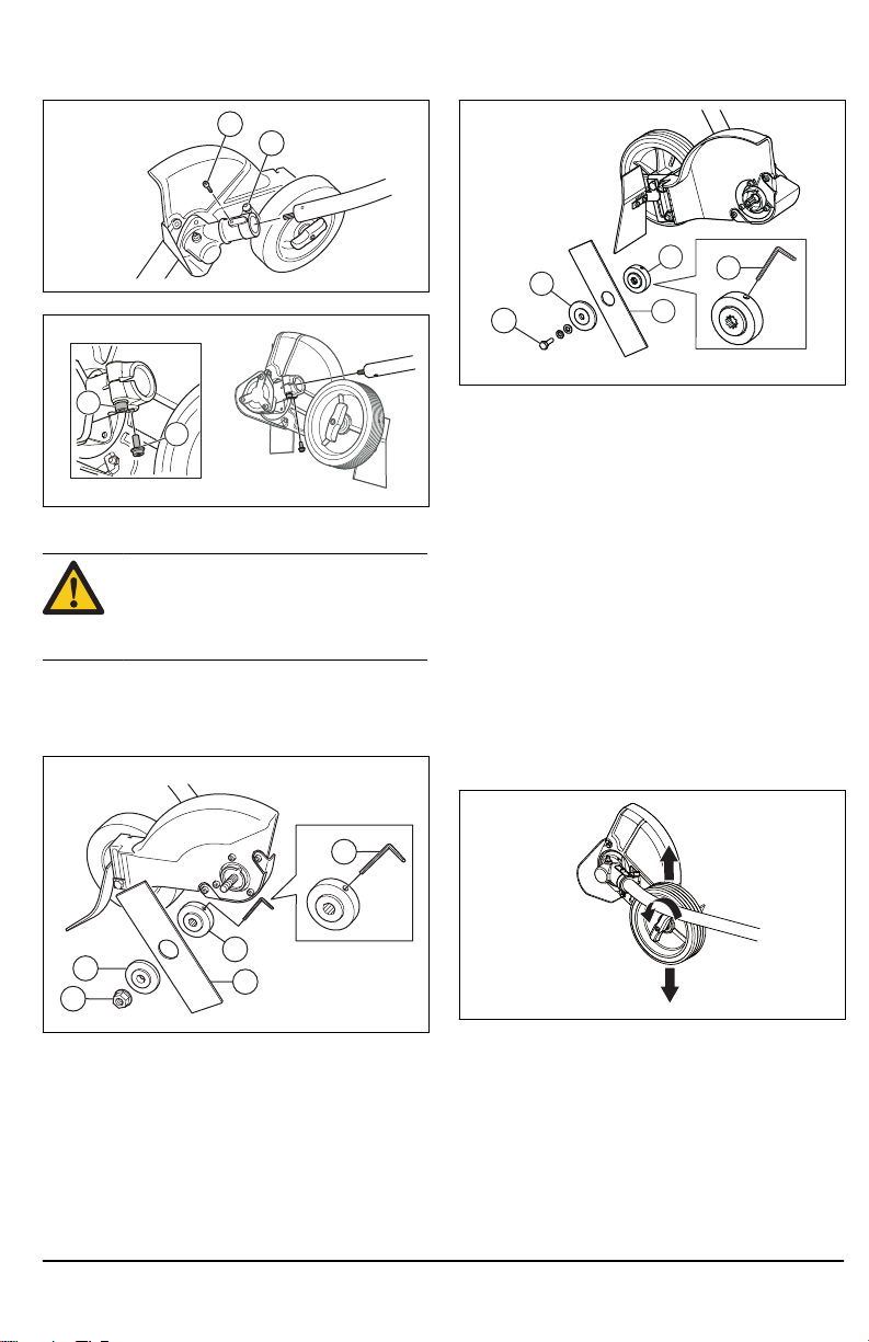
To assemble the cutting attachment
WARNING: Never use a cutting attachment
without without an approved cutting
attachment guard. If an incorrect or faulty
cutting attachment guard is fitted this can
cause serious personal injury.
1. Fit the drive disc (A) on the output shaft. Make sure
that the edge of the drive disc, that fits in the hole of
the blade, is facing outwards.
a) For model ECA850:
b) For model ESA850:
2. Lock the blade rotation by inserting the locking pin
(E) in the hole on the drive disc.
3. Fit the blade (B) on the drive disc.
4. Fit the support flange (C). The support flange must
be fitted so that its outer edge presses against the
cutter.
5. Fit the locknut / blade mounting bolt (D). The
locknut / blade mounting bolt has a left-hand thread.
Tighten the locknut / blade mounting bolt to a torque
of 15-20 Nm / 12-15 ft-lb.
6. Remove the locking pin.
To adjust the cutting depth of the cutting attachment
The cutting depth of the cutting attachment must be
adjusted before starting work.
1. Loosen the wing nut.
a) For model ECA850:
878 - 001 - 23.10.2018
7
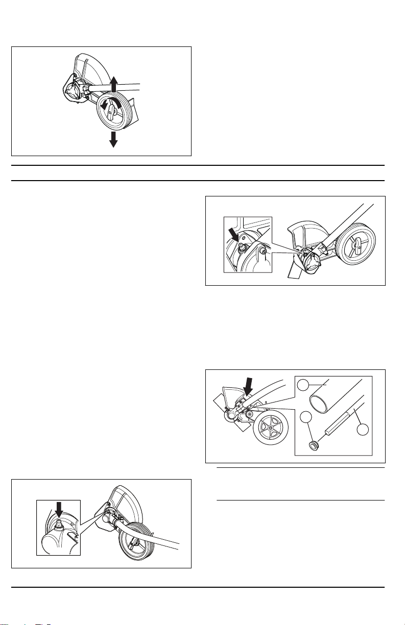
b) For model ESA850: 2. Set the desired cutting depth.
C
B
A
3. Tighten the wing nut.
Maintenance
Introduction
Below you will find some general maintenance
instructions. If you need further information please
contact your service workshop.
To perform daily maintenance
• Check that the blade does not rotate when the
engine is idling.
• Check that the cutting attachment guard is
undamaged and not cracked. Replace the cutting
attachment guard if it has been exposed to impact or
is cracked.
• Check that the blade is not damaged and not
cracked. Replace the blade if necessary.
• Check that the support flage is not damaged.
• Check that the locknut is tight.
To perform weekly maintenance
• Check that the bevel gear is filled to ¾ with grease.
Fill if necessary using special grease.
To check the bevel gear
The bevel gear is filled with the right quantity of grease
at the factory. The grease in the bevel gear does not
normally need to be changed except if repairs are
carried out.
• Before using the product check that the bevel gear is
filled to ¾ with grease. Fill if necessary using special
grease.
a) For model ECA850:
8
b) For model ESA850:
To lubricate the flexible drive shaft
Only for model ECA850.
1. Loosen the 2 screws on the bevel gear.
2. Remove the bevel gear.
3. Take a firm grip on the hollow shaft (A) and remove
the flexible drive shaft (B) from the opposite end of
the gear box.
Note: The bushing (C) will fall off when you remove
the flexible driveshaft. Make sure that you do not
lose it. Put the bushing safely aside.
4. Lubricate the entire length of the flexible drive shaft.
5. Reinsert the flexible driveshaft in the hollow shaft.
Turn the flexible driveshaft while inserting it so that it
correctly engages in the bevel gear.
6. Attach the bushing on the flexible drive shaft.
7. Attach the bevel gear on the hollow drive shaft and
tighten the 2 screws.
878 - 001 - 23.10.2018

Technical data
Technical data
ECA850, ESA850
Weight, Lbs / kg 3.5 / 1.6
Blade length, inch / mm 7.7 / 195
Center hole, blade, inch / mm 1 / 25.4
Speed, blade, rpm 7140
878 - 001 - 23.10.2018 9
Contenido
1
4
10
11
12
5
2
3
6
7
9
ESA 850
5
3
2
1
4
7
6
8
ECA 850
Introducción.................................................................. 10
Seguridad..................................................................... 11
Montaje......................................................................... 15
Introducción
Descripción de la máquina
Husqvarna AB tiene una política de desarrollo continuo
de productos y, por lo tanto, se reserva el derecho de
modificar el diseño y el aspecto de los productos sin
previo aviso.
Uso específico
ADVERTENCIA: Utilice este accesorio solo
con productos para los que se diseñó.
Consulte el capítulo de accesorios en el
manual de usuario del producto.
Vista general del accesorio
Mantenimiento.............................................................. 16
Datos técnicos.............................................................. 17
Utilice el accesorio solo para el bordeado de césped.
1. Hoja
2. Tapón de llenado de grasa, engranaje angulado
3. Engranaje angulado
4. Protección del equipo de corte
10 878 - 001 - 23.10.2018
5. Eje
6. Disco de arrastre
7. Brida de apoyo
8. Contratuerca
9. Perno de montaje de la hoja
¡ADVERTENCIA!
10. Llave combinada
11. Pasador de bloqueo
12. Manual de usuario
Símbolos en el equipo de corte
El uso incorrecto o descuidado de este
accesorio puede ocasionar lesiones graves
o mortales al operador u otras personas.
Lea cuidadosamente el manual de usuario y
asegúrese de que entiende las instrucciones
antes de utilizar el accesorio.
Use siempre protectores auriculares
aprobados y gafas protectoras o un visor.
Se debe utilizar una máscara respiratoria
cuando exista riesgo de polvo.
Use siempre guantes protectores
aprobados.
Use botas antideslizantes y resistentes.
Propuesta 65
Cuchilla giratoria. Mantenga las manos y los
pies alejados. La flecha indica el sentido de
rotación.
Tenga cuidado con los objetos que puedan
salir despedidos o producir algún impacto
por efectos de rebote.
La hoja continúa girando, incluso después
de detener el motor.
Mientras trabaja, el operador
del equipo se debe asegurar de
que ninguna persona o animal
se acerque a menos de 15 metros (50 pies).
Tenga en cuenta: Otros símbolos o etiquetas en el
equipo hacen referencia a requisitos de certificación
especiales para ciertos mercados.
Seguridad
Definiciones de seguridad
Las advertencias, precauciones y notas se utilizan para
señalar las piezas particularmente importantes del
manual.
ADVERTENCIA: Se utilizan para señalar el
riesgo de lesiones graves o mortales para el
operador o para aquellos que se encuentren
cerca si no se siguen las instrucciones del
manual.
878 - 001 - 23.10.2018 11
Tenga en cuenta: Se utilizan para entregar más
información necesaria en situaciones particulares.
AVISO: Se utilizan para señalar el riesgo de
dañar la máquina, otros materiales o el área
adyacente si no se siguen las instrucciones
del manual.
 Loading...