

Page 1

HUSQVARNA CONSTRUCTION PRODUCTS
English
DXR-310
Please read the Operator’s Manual carefully and make sure you
understand the instructions before using the machine.
Page 2

Page 3

CONTENTS
Contents
INTRODUCTION
Dear Customer ......................................................... 4
Good service ............................................................ 4
Serial Number ........................................................... 4
Applications .............................................................. 4
User responsibility .................................................... 4
The manufacturer’s reservation ................................ 4
KEY TO SYMBOLS
Symbols on the machine .......................................... 5
SAFETY INSTRUCTIONS
Warning instructions ................................................. 6
Protective equipment ............................................... 6
General safety warnings ........................................... 7
General working instructions .................................... 8
The machine’s safety features .................................. 13
External environmental factors ................................. 15
PRESENTATION
The machine’s functions ........................................... 16
What is what in the machine? .................................. 17
HYDRAULIC SYSTEM
General ..................................................................... 18
Main pressure ........................................................... 18
Pressure cut-off ........................................................ 18
Cooler ....................................................................... 18
The machine’s hydraulic system .............................. 19
ELECTRICAL SYSTEM
General ..................................................................... 20
High-voltage circuit .................................................. 20
Low-voltage circuit ................................................... 20
The machine’s electric system ................................. 21
CONTROL SYSTEM
General ..................................................................... 22
Remote control ......................................................... 22
Signal transmission .................................................. 22
Battery ...................................................................... 22
The machine’s software ............................................ 22
What is what on the remote control? ....................... .23
Symbols on the remote control ................................ 24
STARTING AND STOPPING
Before starting .......................................................... 25
Starting ..................................................................... 25
Stopping ................................................................... 25
Inspection after work ................................................ 25
OPERATION
Operating modes ...................................................... 26
Option ....................................................................... 26
Key to commands .................................................... 26
Designation of the machine’s parts .......................... 26
Work mode ............................................................... 27
Set-up mode ............................................................ 28
Transport mode ........................................................ 29
TOOLS
General ..................................................................... 30
Work mode ............................................................... 30
Changing tools ......................................................... 31
Storage ..................................................................... 31
SETTINGS
Track widener ........................................................... 32
Menu system ............................................................ 33
Operational settings ................................................. 34
MAINTENANCE AND SERVICE
General ..................................................................... .35
Measures to take in advance of maintenance,
service and trouble shooting .................................... 35
Cleaning ................................................................... 36
Service schedule ...................................................... 37
Service review .......................................................... 40
TROUBLE SHOOTING
Error messages ........................................................ 47
Troubleshooting schedule ........................................ 48
TECHNICAL DATA
Guide values for main connection ............................ 50
The hydraulic system pressure ................................. 50
Hydraulic fl uid and lubricant ..................................... 51
Preset limit values .................................................... 51
Technical data .......................................................... 52
EC-DECLARATION OF CONFORMITY
EC-declaration of conformity ................................... 56
English - 3
Page 4

INTRODUCTION
Dear Customer
Thank you for choosing a Husqvarna DXR-310!
We hope you will fi nd this operator’s manual very use-
ful. By following its instructions (on operation, service,
maintenance, etc.) you will signifi cantly extend the life
of the machine and even its second-hand value.
Good service
Husqvarna products are sold all over the world and
ensures that you, the customer, get the best support
and service. When you need spare parts or advice on
service or warranty issues, go to www.husqvarnacp.
com and fi nd your local service agent.
Serial Number
The machine’s serial number is indicated on a plate
located on the hydraulic tank. Stated on the plate are:
• The machine’s type designation
• Weight
• The manufacturer’s type number
• The machine’s serial number
• Manufacturer
The hydraulic pump and hydraulic motors are fi tted
with rating plates that indicate article number and the
machine manufacturer’s manufacture number.
Please state the type designation and serial number
when ordering spare parts and for service matters.
Applications
The machine is intended for:
• Demolishing, fragmenting, cutting, detaching,
separating, picking up and distributing parts of
buildings and constructions.
• Use in risky environments where the operator can
control the machine without being present within
the risk area.
• Use both indoors and outdoors.
• Use in dangerous environments where the machine
is exposed to risk of collapse, hazardous substances, great heat, etc.
The machine is NOT intended for:
• Use in areas classifi ed as ’explosive”.
• Use in water where the level risks damaging the
machine’s equipment.
• Operation on a public highway.
• Use as a towing vehicle, means of transport or lifting device.
• Use in environments where there is danger for
the operator or the life and health of people in the
vicinity.
• Use in applications or environments that are not
compatible with the recommendations in this Operator’s Manual.
User responsibility
It is the owner’s/employer’s responsibility that the operator has suffi cient knowledge about how to use the
machine safely. Supervisors and operators must have
read and understood the Operator’s Manual. They
must be aware of:
• The machine’s safety instructions.
• The machine’s range of applications and limitations.
• How the machine is to be used and maintained.
The manufacturer’s
reservation
Husqvarna Construction Products reserves the right
to alter specifi cations and instructions for the machine
without prior notifi cation. The machine may not be
modifi ed without the manufacturer’s written permis-
sion. If the machine is modifi ed after delivery from
Husqvarna Construction Products and without the
manufacturer’s written permission, it is the owner’s
responsibility.
Modifi cation can entail new risks for operators, the
machine and the surroundings. These can include
impaired strength or inadequate protection. It is the
responsibility of the owner to specify which alterations are going to be made and to contact the supplier
of the machine for approval before commencing the
modifi cations.
• Use in environments classifi ed as ’fl ammable”
provided that it has the correct power connection
and all its equipment is correctly dimensioned and
undamaged. The operator must take the risk of
spark formation into consideration when working in
fl ammable environments..
4
- English
All information and all data in the Operator’s Manual
were applicable at the time the Operator’s Manual was
sent to print.
Contact
Husqvarna Construction Products, Jons väg 19,
SE-433 81 Göteborg, Sweden.
Page 5
KEY TO SYMBOLS
English - 5
Symbols on the machine
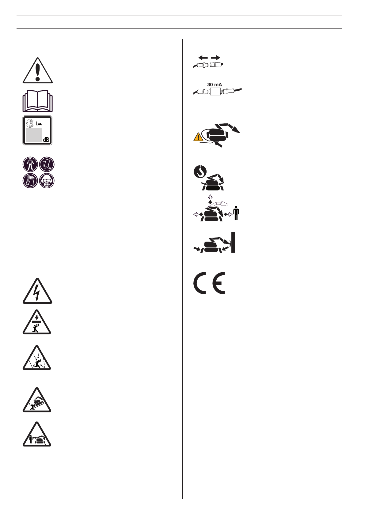
WARNING! The machine can be dangerous if used incorrectly or carelessly, and
can cause serious or fatal injury to the
operator or others.
Please read the Operator’s Manual carefully and make sure you understand the
instructions before using the machine.
Noise emission to the environment according to the European Community’s
Directive. The machine’s emission is
specifi ed in chapter Technical data and on
label.
Always wear:
• Tight-fi tting, heavy-duty and comfort-
able clothing that permit full freedom
of movement.
• Sturdy, non-slip boots or shoes.
• Protective gloves.
• Protective helmet.
• Hearing protection.
• Protective goggles or visor.
• A breathing mask, gas mask or fresh
air helmet must be used when working in environments where the air can
be harmful to health.
WARNING! High-voltage current.
Inspections and/or maintenance must be
carried out with the motor switched off
and the power cord disconnected.
Always connect the machine
through an earth-fault breaker with
personal protection, i.e. an earth
fault circuit breaker that trips at an
earth fault of 30 mA.
Ensure that the power cable cannot be run over. Take particular care
when moving or when the outriggers
are being retracted or extended.
Risk of electric shock.
The lifting equipment must be attached at
all the machine’s lifting points.
Keep your distance! Nobody is
permitted to be within the machine’s
risk area when work is underway.
The machine’s risk area can vary
during the course of the work.
The machine can overturn during
work. During operation the machine
must be positioned as level as possible and the outriggers must be fully
extended.
This product is in accordance with applicable EC directives.
WARNING! Ensure that no material can fall
down and cause damage when you are
using the machine.
WARNING! Watch out for demolition material becoming loose when cutting. Use
personal safety equipment and keep your
distance.
WARNING! Always position yourself above
the machine when driving on a slope.
There is a risk of the machine tipping.
WARNING! Exercise particular caution
when working close to edges. Ensure that
the machine is stable and does not move
closer to the edge while the work is in
progress. Ensure that the underlying surface has satisfactory bearing capacity.
Page 6

SAFETY INSTRUCTIONS
Warning instructions
Warning
WARNING!
Used if there is a risk of serious injury or death
for the operator or damage to the surroundings
if the instructions in the manual are not followed.
Important
IMPORTANT!
Used if there is a risk of injury to the operator or
damage to the surroundings if the instructions in
the manual are not followed.
Note
NB! Used if there is a risk of damage to materials or
the machine if the instructions in the manual are not
followed.
Protective equipment
Personal protective equipment
WARNING!
You must use approved personal protective
equipment whenever you use the machine.
Personal protective equipment cannot eliminate
the risk of injury but it will reduce the degree
of injury if an accident does happen. Ask your
dealer for help in choosing the right equipment.
Always wear:
• Protective helmet.
• Hearing protection.
• Protective goggles or a visor.
• Tight-fi tting, heavy-duty and comfortable clothing
that permits full freedom of movement.
• Protective gloves.
• Sturdy, non-slip boots or shoes.
• A breathing mask, gas mask or fresh air helmet
must be used when working in environments where
the air can be harmful to health.
• Always have a fi rst aid kit nearby.
Other protective equipment
• Fall protection must be used when working at
height or if there is a risk of collapse. The operator
and the machine must be safeguarded with separate fall protection.
• Screening equipment and modifi ed protective
clothing must be used when working in hot environments.
• Barriers must be used to inform people in the vicinity of the machine’s risk area.
• Equipment must be used to secure machine parts
during maintenance and service.
6 - English
Page 7

SAFETY INSTRUCTIONS
General safety instructions
WARNING!
Please read the Operator’s Manual carefully
and make sure you understand the instructions
before using the machine.
The machine is used in a large range of environments
and for different types of work, making it impossible
to forewarn of all risks. Always exercise care and use
your common sense. Avoid all situations which you
consider to be beyond your capability. If you still feel
uncertain about operating procedures after reading
these instructions, you should consult an expert before
continuing.
Do not hesitate to contact your dealer if you have any
more questions about the use of the machine. We will
willingly be of service and provide you with advice as
well as help you to use your machine both effi ciently
and safely.
Use the safety instructions as guidelines and support
so that you can detect possible risks yourself and take
measures to prevent them.
Let your Husqvarna dealer regularly check the machine and make essential adjustments and repairs.
Management and operator
The management and the operator are responsible
for identifying and preventing risks so that staff and
equipment are not exposed to danger.
Responsibility
It is the responsibility of the management and the
operator to confi rm:
• National and local laws, regulations and other
directions are followed. This might concern protective equipment, limit levels for noise, barriers, etc.
• The operator has the relevant training and experience to be able to perform the work safely.
• Unauthorized persons are not permitted to enter
areas where there is a risk of accidents.
Requirements of the operator
• The operator must be given suffi cient information
and training to have satisfactory knowledge of the
machine’s functions, properties and limitations.
• The operator must try to foresee risky elements of
the job and assess the machine’s risk area. Always
exercise caution and use common sense!
• It is the responsibility of the operator to suspend
work with the machine if a safety risk arises and
ensure that the machine is not used by mistake.
The machine must not be put into operation before
the safety risk has been eliminated.
• The operator must not be under the infl uence of
drugs or anything else that can affect his/her reactions or judgement.
• The operator must use protective equipment suited
for the particular work situation.
• The operator must ensure that the machine cannot
be used by unauthorized persons, e.g. do not leave
the remote control unattended.
If there is an accident
It is the responsibility of the employer to produce an
action plan and train operators how to deal with incidents. First take action to save human life and second
to avoid material damage. Learn how to administer
fi rst aid!
Measures to take in the event of an accident:
• Get an overview. Is anyone injured? Is anyone still
in the area where the accident took place?
• Alert emergency services and be prepared to provide information.
• Administer fi rst aid and prepare a route for the
emergency personnel.
• Ensure that someone accompanies the injured to
the hospital.
• Secure the scene of the accident.
• Contact management.
• Nobody is permitted to be within the machine’s risk
area when work is underway.
• Persons who are admitted to the work area are
trained in and have access to protective equipment.
• The machine is used solely for the functions for
which it is intended.
• The machine is used safely.
• The machine is correctly connected to a suitable
power supply and correctly fused.
• The operator is informed of the work area surroundings, e.g. strength in the fl oor structure, positioning
of load-bearing walls, cables and pipes.
• Contact relatives.
• Investigate the cause of the accident.
• Put measures in place to prevent future accidents.
• Always notify Husqvarna Construction Products in
the event of near-accidents or accidents regardless
of whether the machine was directly or indirectly
involved in the incident.
English - 7
Page 8
SAFETY INSTRUCTIONS
8 - English
General working
instructions
WARNING!
Read all safety warnings and all instructions.
Neglecting to follow the warnings and instructions can lead to serious injury or death for the
operator or others..
This section describes basic safety directions for
using the machine. This information is never a substitute for professional skills and experience. If you get
into a situation where you feel unsafe, stop and seek
expert advice. Contact your dealer, service agent or
an experienced user. Do not attempt any task that you
feel unsure of!
Work area safety
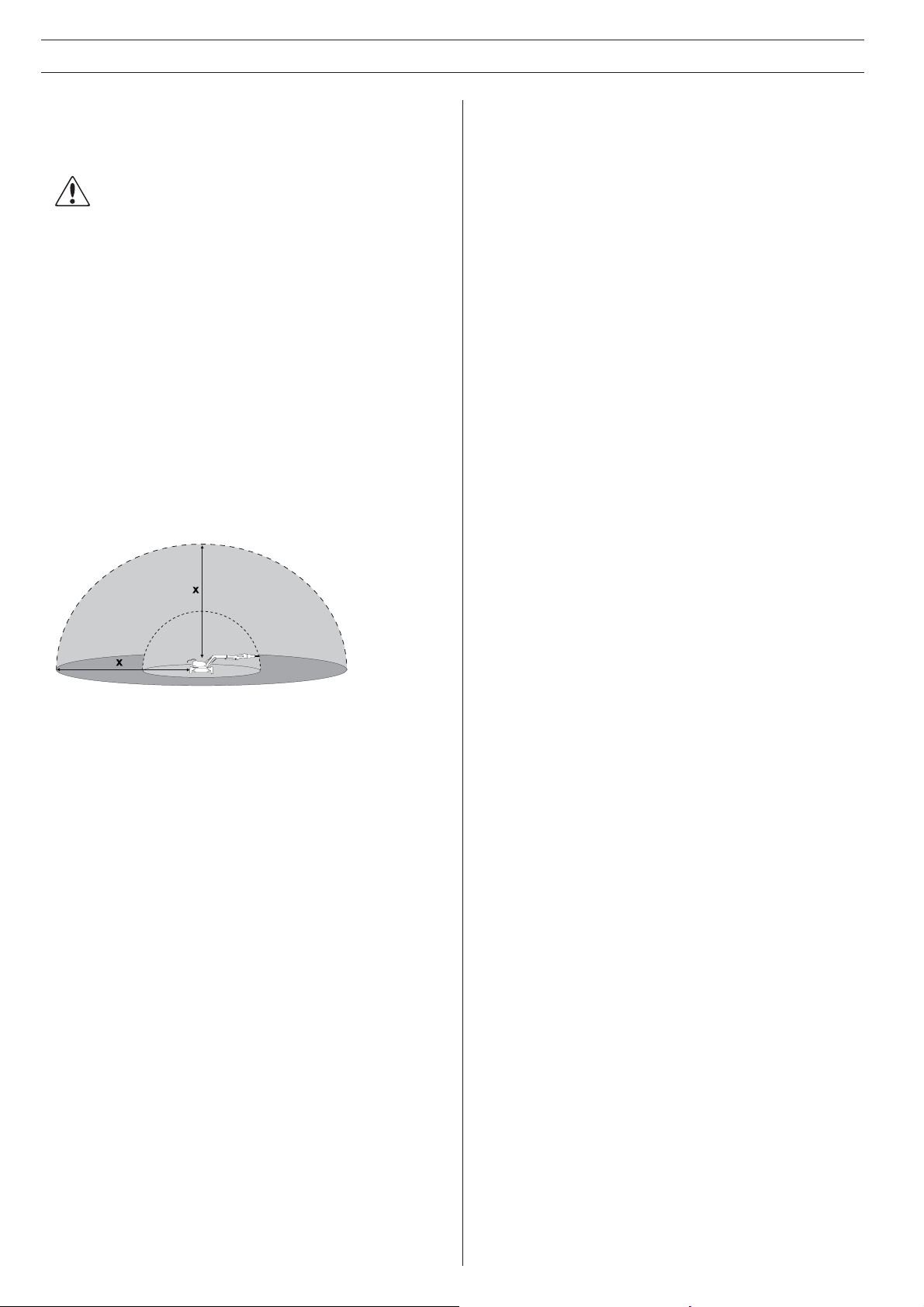
The machine’s risk area
Nobody is permitted to be within the machine’s risk
area when work is underway.
• When working at a height, for instance on roofs,
platforms and the like, increase the size of the risk
area. Defi ne and cordon off the risk area at ground
level and ensure that no material can fall down and
cause injury.
• Ensure when cutting that no material can become
loose and fall, causing operating injury. Take great
care when working on sloping ground.
• Do not use the machine in environments where
there is a risk of explosion. Take the risk of spark
formation into account when working in fl ammable
environments.
• Always check and mark where electricity cables
and pipelines are routed.
• The air in confi ned spaces can rapidly become
harmful to health due to, for example, dust and
gases. Use protective equipment and ensure that
there is satisfactory ventilation.
Electrical safety
• Check that the main voltage corresponds with the
machine’s rating plate.
The working area is limited by the machine’s reach,
however, the risk area varies depending on working
method, work object, surface etc. Study possible risks
before starting work. If conditions change during the
course of the work, the risk area must be redefi ned.
Workplace
• Defi ne and cordon off the risk area. Nobody is per-
mitted to be within the machine’s risk area when
work is underway.
• Ensure that the working area is suffi ciently illumi-
nated to create a safe working environment.
• The machine can be remote controlled over long
distances. Do not operate the machine unless you
have clear supervision of the machine and its risk
area.
• Never start working with the machine until the
working area has been cleared of obstacles.
• Be on the alert when working in environments
where there is a substantial risk of slipping due to
unevenness, loose material, oil, ice or suchlike.
• The machine must be connected to a functioning
protective earth.
• Check all cables and connections. Damaged
electric cables can impede the machine’s function
and lead to personal injuries. Do not use damaged
connectors or cables.
• The electric cabinet must not be opened when the
machine is connected to power. Some components
in the electric cabinet are permanently live, even if
the machine is turned off.
• Always connect the machine through an earth-fault
breaker with personal protection, i.e. an earth fault
circuit breaker that trips at an earth fault of 30 mA.
• The machine must never be driven to such a depth
in water that it reaches up to the machine’s equipment. The equipment can be damaged and the
machine can be live, resulting in personal injuries.
• Ensure that the power cable cannot be run over.
Take particular care when moving or when the
outriggers are being retracted or extended. Risk of
electric shock.
• To avoid overheating do not use an electric cable
while it is coiled.
• Always de-energize the machine when carrying
out maintenance work and when it is not in use.
Disconnect the power cable and place it so that it
cannot be connected by mistake.
• Inspect ground conditions, load-bearing structures
etc. to prevent materials, machines and staff falling
and deal with any risks there might be before starting work.
Page 9

SAFETY INSTRUCTIONS
English - 9
Personal safety
• Never use the machine if you are tired, if you have
consumed alcohol, or if you are taking other drugs
or medication that can affect your vision, judgement or co-ordination.
• Wear personal protective equipment. See instructions under the heading ”Personal protective
equipment”.
• Chemicals such as degreasing agent, grease and
hydraulic fl uid can give rise to allergies in conjunc-
tion with repeated skin contact. Avoid contact with
the skin and use protective equipment.
• When in use, the machine can generate dust and
fumes that can contain harmful chemicals. Know
the nature of the material being worked on and
wear appropriate dust mask or respirator protection.
A face mask is especially important when working indoors due to the limited ventilation. In some
situations it can also be suitable to apply water in
order to decrease the dust.
• Do not stand on the control cable or the power cable as there is a risk of your feet becoming tangled.
• Do not use remote control with cable steering while
working or moving where there is a risk that the
machine can topple. The operator must be disengaged from the machine.
• An incorrect manoeuvre or unforeseeable incident
can result in collapse. Never stand underneath the
work object.
• Never stand where there is a risk of being crushed.
The machine can rapidly change position. Never
stand underneath a raised arm, even if the machine
is turned off.
• Reduce the risk when working alone by making
sure that an emergency alarm is available via mobile phone or other equipment.
• When moving on a fl at surface you must always
walk behind or at the side of the machine. When
working or moving on a sloping surface position
yourself above the machine.
Operation
General
• Only authorized and trained operators are permitted to operate the machine and its tools.
• Never use a defective machine. Carry out inspections, maintenance and service in accordance with
the instructions in the Operator’s Manual.
• Rectify any faults or damage that occur immediately. Prevent the machine from being used before
the fault has been rectifi ed.
• The machine has been tested and approved solely
with equipment supplied and recommended by the
manufacturer.
• Under no circumstances should you modify the
original design of the machine without approval
from the manufacturer. Always use original spare
parts. Unauthorized modifi cations and/or accesso-
ries may lead to serious injury or death to the user
or others.
• Do not modify the machine’s safety devices and
check regularly that they are working properly. The
machine must not be driven if protective plates,
protective covers, safety switches or other protective devices are not fi tted or are defective.
• Make sure all nuts and bolts are tightened correctly.
• The machine must be kept clean. Signs and stickers must be fully legible.
• Follow the machine’s and the tool’s instructions
carefully when changing tools in order to avoid
injuries.
• Turn off the electricity supply to the machine before
you take off the remote control or when you leave
the machine to avoid the risk of unintentional operation.
• Firm handling of the joysticks does not make the
machine stronger or faster. On the contrary, the
joysticks can buckle with unnecessary repairs as a
consequence.
• Do not lift the remote control by the joysticks.
Education and training
• New operators must be trained by experienced
operators with the capacity to use sound judgment
when supervising the work.
• Practice stopping the machine and locating the
stop button quickly. Practice manoeuvring in different directions, on a slope and different surfaces.
• Test the machine’s stability under controlled conditions. Practice rapid evacuation.
• On completion of the training, the operator should
be properly acquainted with the machine’s limitations with respect to reach, capacity and stability,
and also be able to manoeuvre the machine safely.
Page 10
SAFETY INSTRUCTIONS
10 - English
Manoeuvring
General
• If several machines are used at the same workplace
there is a risk of mixing up the remote controls.
Switch on the current to the remote control and
the machine. Press the horn to see which machine
is connected to the remote control. The machine
will beep and fl ash three times. Do not activate the
remote control before you have ensured that the
correct machine is being operated.
• Wait until the remote control has been turned off
and the motor has stopped before you enter into
the machine’s risk area.
• Never leave the machine unsupervised with the
motor running.
• The machine can overturn during work. During operation the machine must be positioned as level as
possible and the outriggers must be fully extended.
• In some cases it can be diffi cult to determine which
end of the machine is the front and which is the
rear. Look at the direction markings on the sides of
the machine’s tracks to avoid incorrect operation.
Arm system
• Do not use the arm system and the rotation function for striking, demolishing or scraping.
• Do not work with the arm if the machine’s outriggers are folded. The outriggers provide stability
and reduce the risk of the machine tipping.
• When the arm system’s reach is being used, the
load increases as does the risk of tipping. Position the machine as close to the working object as
possible.
• Never use the telescopic arm to press the tool
against the working object.
• Do not secure the machine to fi xed objects, e.g.
walls, to increase the force on the working object.
Both the machine and the tool can be subject to
overloading.
Outriggers
• When the outriggers are folded, the arm must be
retracted to minimize the risk of the machine overturning.
• The machine’s outriggers can leave the ground,
especially when working with a hydraulic hammer or
bucket. The higher the machine rises the greater the
load the rest of the support mechanism is subject
to.
• When working with a hydraulic hammer there is an
increased risk of the machine tipping or landing with
a large force on the outrigger on impact. Take this
risk into account and institute appropriate safety
measures to avoid any personal injury or mechanical
damage.
Rotation function
• If there is a breakdown in the machine’s rotation
mechanism the machine’s upper part may rotate
freely, potentially causing personal injury or mechanical damage. Keep your distance.
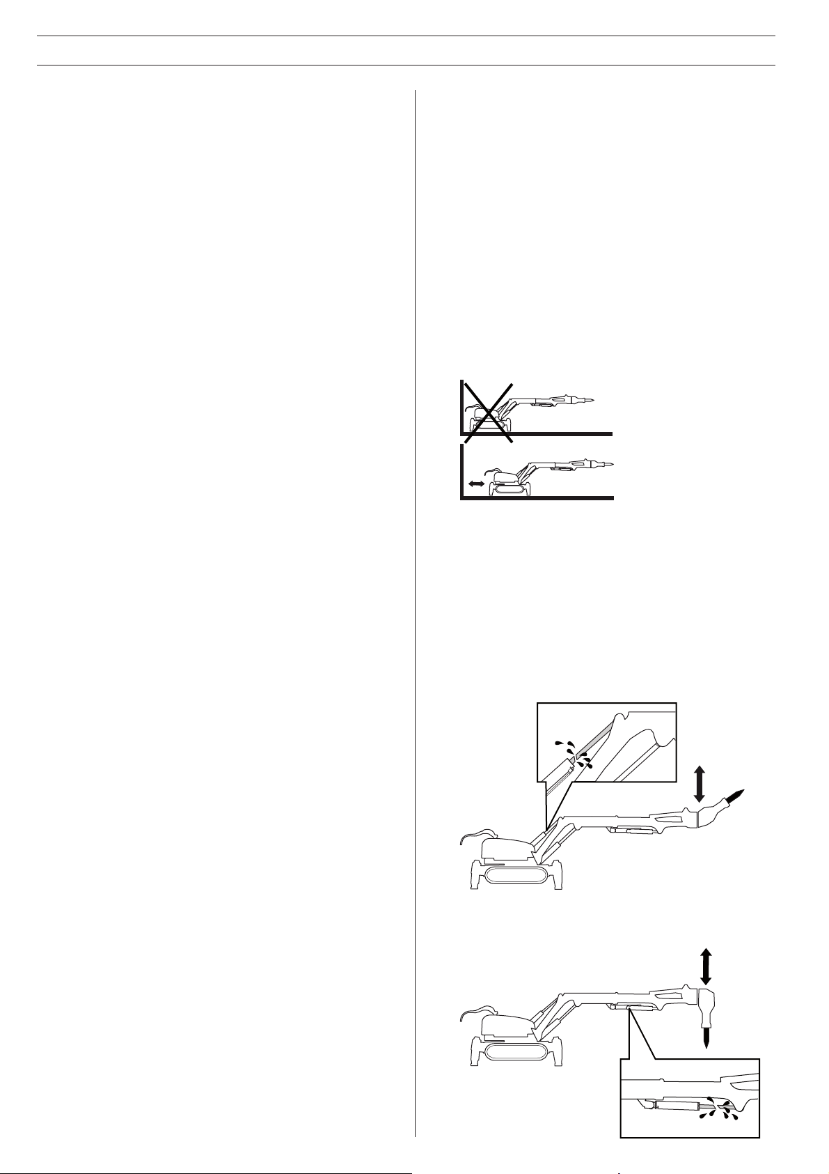
• The machine is most stable when working directly
forwards or backwards. When the machine’s upper
part rotates to the side, the outriggers should be
down and the arm system manoeuvred so that it is
as close to the ground as possible.
• In some cases it can be diffi cult to predict the
direction of rotation. Operate the turning motion
carefully until you have apprehended the direction
of rotation.
• Do not work with the machine’s cylinders in the
inner or outer end positions to avoid overloading.
Leave a few centimetres to the maximum position.
The hydraulic fl uid then has a greater capacity to
alleviate impacts and vibrations.
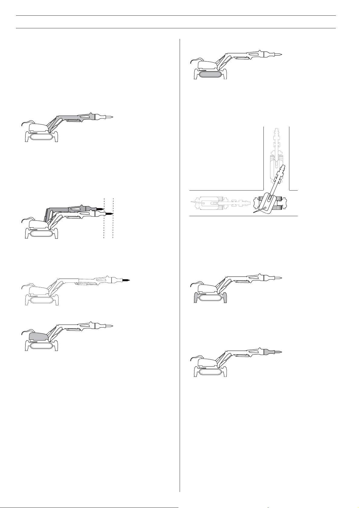
• There are two working positions that put a lot of
strain on individual cylinders.
Cylinders 1 and 2 are in their outer positions and
the hammer is working in the upward direction.
Never operate the cylinders to their end positions.
Cylinder 3 is in its outer position and the hammer is
working in the downward direction. Never operate
the cylinders to their end positions.
Page 11

SAFETY INSTRUCTIONS
Proximity to edges
• Inadequate surfaces, incorrect operation, etc. can
cause the machine to slide. Exercise particular caution when working close to shafts, beside trenches
or when working at height.
• Always anchor the machine and loose tools when
working close to edges.
• Ensure that the machine is stable and does not
move closer to the edge while work is in progress.
• Ensure that the underlying surface has satisfactory
bearing capacity. Vibrations affect bearing capacity.
Uneven surfaces
• Extend the outriggers so that they are positioned
just above the surface when moving over uneven
areas.
• In some cases the arm can be used to lift the drive
gear over bumps. The arm must never be rotated
or raised up high due to the risk of overturning.
• Uneven surfaces can cause the machine to lean
to such an extent that it overturns. Manoeuvre the
machine’s arm system inwards in order to move
the centre of gravity as close to the machine’s centre as possible to reduce the risk of tipping.
• Surfaces with a poor bearing capacity can cause
the machine to change direction or even overturn
without warning. Always check the bearing capacity and properties of the surface before starting the
machine. Also be alert for holes that are covered
by materials with a poor bearing capacity.
• The machine’s caterpillar tracks produce a low
level of friction against smooth surfaces. Water,
dust and contaminants can further reduce friction.
When defi ning the risk area you should take into
account the fact that less friction increases the risk
of the machine starting to slide.
Confi ned spaces
• Working in confi ned spaces with extended outrig-
gers can be diffi cult. The machine’s stability is con-
siderably diminished. Adapt the work accordingly.
There is an increased risk of the machine overturning if the arm swings outside the outrigger.
Sloping ground
• Sloping surfaces, stairs, ramps etc. can constitute
major risks when moving and working. With gradients in excess of 35° there is a risk of the machine
tipping.
• The machine’s arm system and outriggers must be
positioned as low as possible to reduce the risk of
tipping.
• Do not run the caterpillar tracks and tower simultaneously when moving on a sloping surface to
reduce the risk of unexpected motion.
• Avoid driving sideways on slopes - drive straight
up or down. Ensure that the machine’s arm system
is turned upwards in sloping terrain.
• Always position yourself above the machine when
driving on a slope. There is a risk of the machine
tipping.
• Anchor the machine if there is a risk of the machine
starting to move.
• Check that there is suffi cient bearing capacity
when driving on ramps and stairs.
Proximity to ducts and pipes
• Always check and mark where electricity cables
and pipelines are routed. Ensure that electricity
cables and pipelines are shut off.
• The machine must not get close to overhead cables. The current can “jump” over long distances.
Falling material
• Watch out for demolition material becoming loose
when cutting. Use personal safety equipment and
keep your distance.
• Ensure that the vibrations from the hydraulic hammer do not cause cracks to form or stones or other
material to loosen and cause personal injury or
damage to property. Keep your distance!
• When moving in confi ned spaces it is possible to
reduce the width of the tracks, increasing the risk
of the machine overturning. There is an increased
risk of the machine overturning if the arm swings
outside the outrigger.
English - 11
Page 12
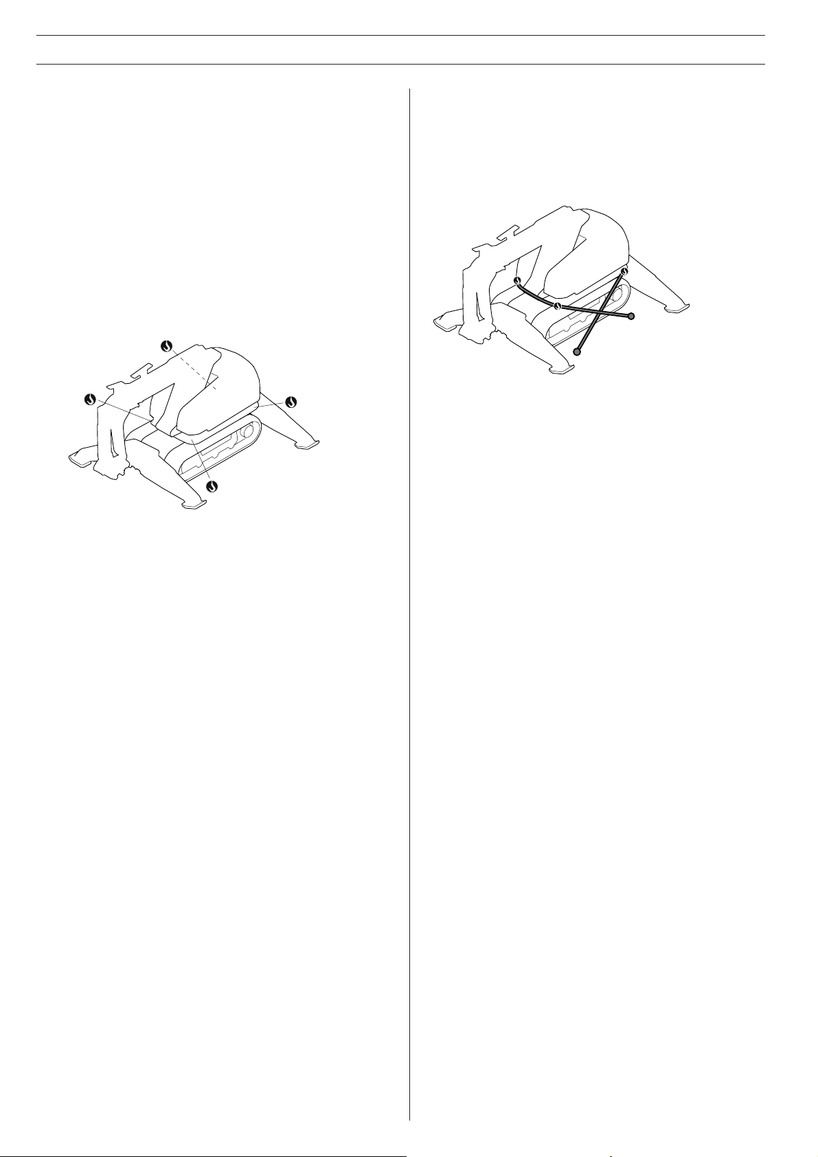
Securing the machine
• Secure the machine with approved tightening
straps. Use the machine’s lifting eye bolts. Ensure
that no part of the machine are squashed or damaged by the tightening straps. It is a good idea to
cover the machine.
• Tools and other equipment must be secured with
separate tightening straps.
• Regularly check that the load is secure during
transportation.
Storage
• Remove the tool from the machine.
• Retract the arm system to attain a centre of gravity
that is as low as possible and to save space.
• Store the equipment in a lockable area so that it is
out of reach of children and unauthorized persons.
• Store the machine and its equipment in a dry and
frost proof place.
Towing
The machine is not designed to be towed. When the
machine is depressurized, the drive motor’s parking
brakes are activated and the caterpillar tracks cannot
rotate. Only tow the machine if its position constitutes
a risk and there is no other solution. Tow it for the
shortest possible distance.
• If possible, retract the outriggers before towing the
machine in order to reduce the risk of them getting
stuck and being damaged.
• To minimize the load on the towing device and
mechanical components, reduce the friction by
preparing the route that the machine is going to be
towed.
• If possible tow in the direction of the tracks.
• Use the lifting eye bolts to connect to the towing device. Use a towing device intended for the
particular load.
• Parts can loosen during towing. Keep your distance!
SAFETY INSTRUCTIONS
12 - English
Transport and storage
Lifting the machine
• When lifting the machine there is a risk of injuring
persons or damaging the machine or the surroundings. Defi ne the risk area and check that nobody is
present within the area when lifting.
• Use an approved lifting device to secure and lift
heavy machine parts. Also ensure that there is
equipment to secure machine parts mechanically.
• Retract the arm system. The centre of gravity must
be as close to the machine’s centre as possible.
• The lifting equipment must be attached at all the
machine’s lifting eye bolts.
• Lift slowly and carefully. Make sure that the lift is in
equilibrium and if the machine starts to lean, rectify
it by using an alternative lifting device or change
the position of the arm system.
• Ensure that the machine’s parts are not crushed or
damaged when lifting and that the machine does
not hit surrounding objects.
Loading and unloading using a ramp
• Ensure that the ramp is intact and the right size for
the machine.
• Check that the ramp is free of oil, mud or anything
else that might make it slippery.
• Ensure that the ramp is properly secured to both the
vehicle and the ground. The vehicle being used for
transportation must also be secured so that it cannot
move.
Transport
• The machine may only be transported on a fl atbed
truck or a trailer that is approved for the machine’s
weight, refer to the machine’s rating plate. The
remote control must be properly protected in the
vehicle during transportation.
• Check applicable road traffi c regulations before
transporting on public roads.
The machine’s position on the loading platform
• Position the machine against the front edge of the
platform in order to reduce the risk of it sliding
forward if the vehicle brakes.
• Manoeuvre the arm system so that it is resting
against the platform, positioned as low as possible.
Extend the outriggers without lifting the machine.
Page 13

SAFETY INSTRUCTIONS
Maintenance and service
Most accidents involving machines occur during trouble shooting, service and maintenance as staff have
to locate themselves within the machine’s risk area.
Prevent accidents by being alert and by planning and
preparing the work. You can also refer to ’Preparations
for maintenance and service” in the ’Maintenance and
service” section.
• The user must only carry out the maintenance and
service work described in this Operator’s Manual.
More extensive work must be carried out by an
authorized service workshop.
• Never carry out repairs without having the necessary expertise.
• Only trained service personnel are permitted to
intervene in the electrical or hydraulic systems.
• Use personal protective equipment as well as
equipment to mechanically secure machine components during maintenance and service.
• Set out clear signs to inform persons in the vicinity
that maintenance work is in progress.
• If service operations or trouble shooting does not
require the machine to be switched on, the power
cable must be removed and positioned so that it
cannot be connected by mistake.
• Ensure there is no current to the machine by removing the power cable before opening or removing the electric cabinet or any other component
that contains electrical current.
• Pipe and hose couplings can remain pressurized
despite the motor being switched off and the power cable disconnected. It must always be assumed
that hydraulic hoses are pressurized and they must
be opened with great care. Relieve the pressure on
the arm system by resting it on the ground and turn
off the electric motor before undoing the hoses.
• Never try to stop hydraulic fl uid leaking from a bro-
ken hose by hand. Finely dispersed hydraulic fl uid
at high pressure can permeate under the skin and
cause very severe injuries.
• When dismantling machine parts, heavy components can start moving or fall down. Secure moving
parts mechanically before loosening screw joints or
hydraulic hoses.
• Use an approved lifting device to secure and lift
heavy machine parts.
• Several components heat up during work with the
machine. Do not commence any servicing or maintenance tasks until the machine has cooled.
• Keep work area clean and well lit. Cluttered or dark
areas invite accidents.
• The machine’s movements can be defective if a
terminal, cable or hose is incorrectly assembled.
Exercise caution during test runs and be prepared
to turn off the machine immediately in the event of
a fault.
The machine’s
safety features
The machine’s safety features can be divided into
safety features for personal protection and those for
mechanical protection. Some of the safety features
provide both mechanical and personal protection.
WARNING!
Do not modify the machine’s safety devices and
check regularly that they are working properly.
The machine must not be driven if protective
plates, protective covers, safety switches or
other protective devices are not fi tted or are
defective.
Personal protection
Indication of zero position
If either of the joysticks is in an operative position
when the remote control is started, the function will be
blocked. The operator is informed of this by means of
an error message appearing on the screen. To reset
the function, the remote control must be turned off
and on again.
The function also protects against faults in the potentiometer or cable breaks.
Signal voltage limitation
Signal voltage limitation prevents the machine executing unexpected movements in the event of a cable
breaking or a short-circuit.
The voltage level of the control signals is limited to
within a maximum and minimum value. If the voltage
level falls outside the permitted interval, the machine
stops.
Joystick guard
The safety feature reduces the risk of unintentionally
moving the machine by locking the control circuit if
the joysticks have been in neutral for three seconds.
The control circuit is activated by means of the left
button on the right joystick. It is activated when the
button is released. This guards against fi xing the but-
ton in an active position.
Radio block
If the remote control has been turned off for two
minutes the electronic unit in the machine is blocked
to radio signals. It is not possible to restart the machine until the supply voltage to the machine has been
turned off and on again.
The safety feature ensures that the operator knows
which machine will start and that the correct remote
control is being used for the machine. This is particularly important when there are several machines at the
same workplace.
English - 13
Page 14

SAFETY INSTRUCTIONS
Identity code
The remote control and the machine are connected
by means of a pre-programmed ID code. The ID code
ensures that the right remote control is used for the
right machine.
If several machines are used at the same workplace
there is a risk of mixing up the remote controls.
Switch on the current to the remote control and the
machine. Press the horn to see which machine is connected to the remote control. The machine will beep
and fl ash three times. Do not activate the remote con-
trol before you have ensured that the correct machine
is being operated.
When steering the machine using cables, the ID code
is suppressed and the same remote control can be
used for different machines if these have the same
control system version.
Automatic frequency hopping
In the event of interference in the communication, the
frequency changes automatically to guarantee interference-free transmission.
Emergency stop/machine stop
When the machine stop on the remote control is
pressed, the power to the circuits controlling the
communication with the machine is interrupted. The
machine engine stops due to the interruption of the
transfer of signals to the machine’s electronic device.
The emergency stop on the machine switches off the
main power to the machine.
Protective earth
The machine and its components are connected to
grounding conductors in the power cable. If there is a
fault, a fuse is tripped and the current is disconnected.
The machine must be connected to a power point with
a protective earth. If there are no grounding conductors, or if they are connected incorrectly, have come
off or are loose in a terminal, the current will remain
connected and touching the machine can be highly
dangerous.
If there is reason to believe that the protective earth
has been damaged, the machine must be turned off
and the power cable removed until such time as the
protective earth has been restored.
Always connect the machine through an earth-fault
breaker with personal protection, i.e. an earth fault
circuit breaker that trips at an earth fault of 30 mA.
Hydraulic brake
Hydraulic motors are used when moving the machine.
All hydraulic motors are fi tted with brakes. These
hydraulic motors contain counter balance valves that
prevent uncontrolled fl ow through the motor, e.g. when
manoeuvring down a slope or when the machine is
parked. The counter balance valve closes the tank
opening when the drive motors are not being operated.
Mechanical brake
The machine’s drive motors are equipped with a mechanical parking brake. The machine is braked until its
drive function is activated.
Mechanical protection
Automatic phase rotation relay
The automatic phase rotation relay prevents the electric motor starting with the wrong rotation direction
thus causing mechanical damage.
Motor protection
To prevent overloading, the motor is equipped with
bimetallic relays in the motor linings that disconnect
the power if the motor gets too hot.
If the motor is too hot it is not possible to operate the
tools. The rest of the machine’s functions can be run
at half speed in order to facilitate evacuation of the
machine from risky environments.
Once the motor’s temperature has fallen to a normal
working temperature all functions can be used again.
The machine’s softstarter is fi tted with a motor cut-out
that trips if the current is too high for too long a period.
The machine’s functions return to normal position after
three minutes.
Fuses
Fuses are used to protect the following components
as well as to prevent fi re in conjunction with faults or if
electrical components are overloaded.
Pressure relief valves
The machine’s hydraulic system is equipped with
pressure relief valves. They protect the hydraulic
system against too high pressure and the mechanical
components against overloading.
Pump-around valve
The pump-around valve drains the hydraulic fl ow into
a tank and relieves the pressure on the hydraulic system. No pressure enters the cylinders and it prevents
the risk of unforeseen movements. This happens, for
example, after three seconds of inactivity.
14
- English
Page 15

SAFETY INSTRUCTIONS
External environmental
factors
Temperature
The ambient temperature, both heat and cold, affects
the machine’s operational reliability. Temperature
variations also have an impact as they produce an
increased risk of condensation forming in the machine’s tanks.
Heat
NB! There is an increased risk of overheating in warm
environments. Both the machine’s hydraulic system
and electronic components can be damaged.
The maximum working temperature for hydraulic fl uid
is 90°C (194°F). Overheating results in deposits forming in the fl uid, leading to increased wear, damaged
seals and leakage. Overheated hydraulic fl uid pro-
vides poor lubrication, resulting in inferior performance.
To avoid overheating:
• Keep the machine clean, in particular its cooler.
• Ensure that there is good ventilation when working
indoors.
• Radiant heat can cause local heating that damages parts of the machine. Screen off vulnerable
components.
Moisture
When working in damp environments the operator
should ensure that electrical components, connectors
for example, are not submerged in water.
The machine must never be driven to such a depth in
water that it reaches up to the machine’s equipment.
The equipment can be damaged and the machine can
be live, resulting in personal injuries.
Dust and particles
Dust and particles can block the machine’s cooler,
cause overheating and increase wear on the machine’s bearings and shafts. Clean and lubricate the
machine regularly.
The hydraulic system is extremely sensitive to contaminants. Small particles can cause breakdowns and
increase wear in the components.
There is a high risk of contamination in conjunction
with servicing and repairs when the hydraulic system
is opened.
Contamination of the hydraulic system can be
prevented by:
• Keeping the machine clean, particularly before
servicing, repairs or changing tools.
• Carrying out daily inspections.
• Carrying out regular servicing.
• Additional cooling is required if there are high
ambient temperatures. Supply the machine with
forced cooling using compressed air.
To avoid damage to the machine:
• Change hydraulic fl uid and fi lters more frequently.
• Check the machine’s seals to prevent dirt in the
hydraulic system due to broken seals.
• Rubber caterpillar tracks must not be exposed to
temperatures of over 70°C (158°F). In hotter environments steel tracks have to be used.
Cold
Do not use maximum pump pressure if the hydraulic
fl uid is less than 10°C (50°F). Allow the machine to
warm up slowly. Warm up the lower section by running the caterpillar tracks, fi rst slowly and then more
quickly with the outriggers extended. Move the upper
section back and forth and operate all cylinders in the
arm system without load. The machine is ready for
use when its temperature has risen to around 40°C
(104°F).
English - 15
Page 16
PRESENTATION
16 - English
The machine’s functions
The machine’s functions are operated by means of
interaction between the hydraulic system, the electric
system and the control system.
A brief description of the machine’s functions follows
below.
Arm system
The arm system is divided into three parts in order to
provide extensive movement, a long reach and compactness. Expanding shafts minimize the risk of play
in the joints.
By running cylinder 1 and cylinder 2 in parallel, the
machine’s reach can be modifi ed without moving the
machine.
Caterpillar tracks
The caterpillar tracks are driven individually by hydraulic motors. The machine can be turned by operating
the caterpillar tracks at different speeds. Operating the
tracks in different directions enables the machine to
make tight manoeuvres. When the drive function is not
activated the passive brakes lock the drive motors.
The machine is also equipped with a telescopic arm
that provides additional reach. Work as close to the
work object as possible as this makes optimum use of
the power to the arm system and cylinders.
Tower
The tower has unlimited rotation, which means that is
possible to work in several directions without having
to move the machine. The machine is equipped with a
slew brake. When the rotating function is not activated, the function is braked by means of passive brakes.
NB! The machine’s rotating function must not be subject to overload, e.g. caused by tools that exceed the
weight limit.
In transport mode, the caterpillar tracks and tower can
be manoeuvred simultaneously. The function can be
used, for example, when the machine is being operated in confi ned spaces.
Outriggers
The main function of the outriggers is to give the
machine stability. They must always be used when
working with the machine.
Tools
The machine should be fi tted with tools that are ap-
propriate for the tasks that are to be carried out. The
weight and performance requirement of the tool is
decisive in ascertaining whether it is suitable for use
with the machine. Further information is available in
the ’Tools” and ’Technical data” chapters and the tool
supplier’s instructions.
External tool (optional)
The machine has been prepared with connections
for external hand tools for the machine’s hydraulic
system.
Page 17
PRESENTATION
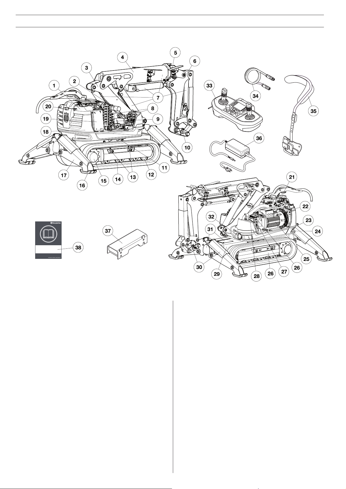
What is what in the machine
1. Hydraulic tank
2. Lubrication pump for lubricating the hammer (accessory)
3. Arm 1
4. Arm 2
5. Telescopic arm
6. Arm 3
7. Cylinders
8. Valve block
9. Slew motor
10. Tool attachment
11. Gear ring
12. Tensioning wheel
13. Screws for widening the tracks
14. Support wheel
15. Drive motor
16. Outrigger foot
17. Outrigger
18. Counterweight in the tower
19. Electric cabinet
20. Emergency stop
21. Warning light
22. Control module
23. Base plate
24. Lifting eye bolts
25. Electric motor
26. Radio module
27. Track unit
28. Hydraulic pump
29. Chassis beam
30. Cylinder guard
31. Inspection covers
32. Work lighting
33. Remote control
34. Communication cable
35. Harness
36. Battery charger
37. Track widener
38. Operator’s Manual
English - 17
Page 18

HYDRAULIC SYSTEM
General
The task of the hydraulic system is to operate the machine’s functions by means of hydraulic pressure and
fl ow. The system consists of hydraulic pump, tank,
cooler, hydraulic motor, hydraulic cylinders, fi lters and
valves of various kinds. Hoses or pipes connect the
components with each other.
Valves are used to control the hydraulic system’s
pressure, volume rate of fl ow and direction. Pressure
control valves limit or reduce the pressure to the value
required. Volume control valves affect the hydraulic
fl uid’s fl ow and thereby the speed of the functions.
Direction control valves direct the hydraulic fl uid to the
machine’s different functions.
The hydraulic pump is of the variable displacement
type and delivers a fl ow of 0-65 l/min (0-17 gal/min).
Main pressure
The hydraulic system has two main pressures.
• Standard pressure is 200 Bar.
• Increased main pressure is 250 Bar.
Increased main pressure is used when the outriggers
are down and when concrete cutters are used with
increased tool pressure.
If concrete cutters with increased tool pressure are
operated at the same time as another function, the
machine returns to standard pressure.
Pressure cut-off
Functions equipped with pressure cut-off have a
reduced pre-set maximum pressure. The telescopic
arm is equipped with a pressure cut-off that produces
a maximum of 180 Bar.
Cooler
The cooler has an integrated bypass valve that protects against overpressure in conjunction with, for
example, cold start.
18
- English
Page 19

HYDRAULIC SYSTEM
English - 19
The machine’s hydraulic
system
1. Air fi lter
2. Oil fi lter
3. Hydraulic tank
4. Cylinder 1
5. Cylinder 5
6. Cylinder 4
7. Cylinder 3
8. Cylinder 2
9. Valve block 1
10. Slew motor
11. Valve block 2
12. Cylinders for outriggers
13. Sight gauge
14. Valve - release track tension
15. Accumulator - track tension
16. Drive motor, drive gear
17. Support wheels
18. Cylinders for track tensioning
19. Tensioning wheel
20. Hydraulic pump
21. Swivel
22. Hose for oil fi lling
23. Filling pump
24. Intermediate piece
Page 20

ELECTRIC SYSTEM
General
The electric system consists of a high-voltage circuit
and a low-voltage circuit.
High-voltage circuit
High-voltage is used as a power source for both the
electric motor and the low-voltage circuit. An automatic phase rotation change-over switch ensures that the
electric motor has the correct rotation direction.
Power supply
The power supply from the main must be suffi ciently
powerful and constant to ensure that the electric motor runs without problems.
Too high or too low voltage causes the electric motor’s power consumption, and consequently also its
temperature, to increase until the motor’s safety circuit
trips.
Fuses
The fuses in the distribution box protect the electrical
system in conjunction with overloading or breakdown.
The power outlet must be correctly fused with respect
to the electric motor, the length of the power cable
and the area of the power cable’s conductor. The table
“Guide values for mains connection” in the “Technical data” section shows which fuse is required for the
electric motor.
The machine is equipped with Softstart and can be
started with most types of fuses.
If a fuse keeps blowing there is a fault in the electrical system or in the machine that is connected to it.
Before restarting the machine the source of the fault
must be removed.
Power cable
The machine is connected to the mains with a 3 phase
power cable. It is very important that the cable that is
used is correctly dimensioned, i.e. that it has the correct cross-sectional area in relation to the length of the
conductor in order to counteract drops in voltage. The
guide values for the cable’s size are set out in the table
’Guide values for main connection” in the ’Technical
data” section.
Low-voltage circuit
The high-voltage current is reduced to low-voltage in
an AC/DC module. It is used to supply power to the
control system and functions such as work lighting
and refi lling pump.
20
- English
Page 21

ELECTRIC SYSTEM
English - 21
The machine’s electric
system
1. Aerial
2. Electric cabinet
3. Pressure switch
4. Temperature sensor
5. Warning light
6. Power cable
7. Electric motor
8. Control module
9. Radio module
10. Work lighting
11. Pressure sensor
12. External tool
13. Main switch
14. Counter
15. Emergency stop
16. Automatic oil refi lling
17. Start button motor
18. Knob for remote control/emergency operating mode
Page 22

CONTROL SYSTEM
Battery
The battery is a Li-ion type. Operating time is about
8-10 hours per charge. Extreme cold impairs the battery’s capacity and operating time. Operating time is
also affected by the extent to which the display has
been active.
To save the battery, the display goes into energy save
mode after 20 seconds. After fi ve minutes of inactiv-
ity the remote control turns off automatically. To use it
again, it must be turned off and on again.
A message appears on the display approx. 30 minutes
before the battery is completely fl at. It is not possible
to activate the remote control if the battery capacity is
too low.
Charging the battery
Before using the remote control for the fi rst time the
battery has to be charged.
Charging time for a fl at battery is approx. 2-3 hours.
The diode is orange when charging starts and becomes green when the battery is fully charged. When
the battery is fully charged the charger supplies the
battery with maintenance current until the battery is
removed from the charger.
Keep the battery charger dry and protected against
temperature fl uctuations.
The machine’s software
Contact your service workshop regarding problems
with the machine’s software or for any updates that
might be needed.
22 - English
General
The remote control, the electronics unit and the pilot
control valves are the main components in the control
system. The signals from the remote control are transmitted to the machine via bluetooth or via a cable. The
electronic unit in the machine transmits the signals
via the pilot control valves to the hydraulic system by
converting electric current into hydraulic pressure.
Remote control
The machine is controlled from the remote control.
Transmission of signals is either wireless, using bluetooth, or via a cable.
The movement of the joysticks is proportional. A small
movement means that the function moves slowly, a
larger movement increases the function’s speed proportionally.
Signal transmission
Identity code
The remote control and the machine are connected by
means of a pre-programmed ID-code. The code is built
into the remote control’s bluetooth transmitter and the receiver on the machine. The ID code cannot be changed.
There is a sticker on the bottom of the remote control
and on the machine’s bluetooth module with a ID code.
The ID code ensures that the right remote control is used
for the right machine.
Wireless signal transmission
Wireless transmission of signals uses bluetooth technology.
Automatic frequency hopping
In the event of interference in the communication, the
frequency changes automatically to guarantee interference-free transmission.
Signal transmission using cables
Connecting a cable shuts off the wireless communication.
When the machine is controlled by means of cables,
the ID code is suppressed and the same remote control can be used for different machines if these have
the same control system version.
Page 23

CONTROL SYSTEM
What is what on the remote
control
1. Left joystick - left button
2. Left joystick - right button
3. Display
4. Right joystick - left button
5. Right joystick - right button
6. Right joystick
7. Main switch
8. Machine stop
9. Left joystick
10-13. Menu buttons
14. Light emitting diode, joysticks active
15. Start button motor
16-19. Menu buttons
20. Flow to machine movement/speed
21. Stop button motor
22. Flow to hydraulic tool
English - 23
Page 24

CONTROL SYSTEM
Symbols on the remote
control
1. Arm 2 telescope out
2. Arm 2 down
3. Right track operation forward
4. Arm 1 and arm 2 out
5. Angle tool outwards
6. Right outrigger down
7. Front/rear right outrigger down
8. Arm 1 out
9. Arm 1 and arm 2 in
10. Right track operation backwards
11. Arm 2 up
12. Arm 2 telescope in
13. Sticker - full fl ow to the tool
14. Sticker - adjustable fl ow to the tool
15. Arm 3 down
2
3
1
16. Left track operation backwards
17. Caterpillar tracks backwards
18. Rear/front left outrigger down
19. Rotation tower anti-clockwise
20. Left outrigger down
21. Caterpillar tracks forward
22. Left track operation forward
23. Arm 3 up
24. Left outrigger up
25. Rotation tower clockwise
26. Rear/front left outrigger up
27. Sticker - open/close cutters
28. Angle tool inwards
29. Right outrigger up
30. Front/rear right outrigger up
31. Arm 1 in
24 - English
Page 25

STARTING AND STOPPING
English - 25
Before starting
The following points should be checked when working
at a new site and every morning before starting:
• Carrying out daily inspections.
• Examine the machine for transport damage.
• Check that the machine’s safety features are intact.
Refer to ’The machine’s safety features” in the
’General working instructions” chapter.
• Check that the power cable and operating cables
are intact and correctly dimensioned.
• Check that the mains voltage is compatible with
the machine and that the correct fuses are used.
• Always connect the machine through an earth-fault
breaker with personal protection, i.e. an earth fault
circuit breaker that trips at an earth fault of 30 mA.
• Check that the emergency stop or machine stop
button are not pressed by turning them clockwise.
• Check that no tools or other objects have been left
lying on the machine.
Starting
Starting the electric motor
• The electric motor is started by pressing the start
button.
• If several machines are used at the same workplace
there is a risk of mixing up the remote controls.
Press the horn to see which machine is connected
to the remote control. The machine will beep
and fl ash three times. Do not activate the remote
control before you have ensured that the correct
machine is being operated.
Activating controls
Connect the machine
• Connect the machine to a 3 phase power supply.
• Turn on the main switch on the machine.
Starting the remote control
• Turn the switch to the ON position (I). In this position the remote control is supplied with current.
The light emitting diode on the remote control
fl ashes rapidly with a blue light when it is searching
for contact. When it fl ashes with a longer interval
the machine is in standby mode.
• To activate the remote control’s operating functions press the left button on the right joystick. The
remote control is now in work mode. The light emitting diode on the remote control has a permanent
blue light.
• If no command is given within three seconds the
operating functions are locked. To return to work
mode, press the left button on the right joystick.
Stopping
• Manoeuvre the arm system down and allow it to
rest against the ground.
• Put all controls into neutral position.
• Press the stop button.
• Put the main switch into the OFF position (O).
• If a function is not working or needs attention, an
error message appears on the display in conjunction with start-up. Refer to ’Error messages” in the
’Trouble shooting” section.
Inspection after work
It can be benefi cial to carry out the daily inspection
after fi nishing work. Detecting damage in time can
prevent a shutdown on the following day.
Page 26

OPERATION
26 - English
Operating modes
The machine can be operated in three different
modes: transport mode, set-up mode and work mode.
All commands in each of the modes are described in
this section.
• Work mode - In this mode you can operate everything except the caterpillar tracks and outriggers.
• Set-up mode - In this mode you can operate the
caterpillar tracks and outriggers.
• Transport mode - In this mode you can operate the
caterpillar tracks and some arm functions.
If no controls have been used for three seconds the
machine goes into idling mode. In this mode hydraulic
oil is pumped into the tank and there is no pressure in
the cylinders.
Option
External tools
External hydraulic tools can be connected to the machine. The mode is activated by pressing the button
for external tools. In this mode the machine cannot be
operated from the remote control.
Key to commands
1 2
3
4
1. Right and left button on right joystick
2. Right and left button on left joystick
3. Direction joystick
4. Left and right joystick respectively
Designation of the
machine’s parts
1. Arm 1
2. Arm 2
3. Arm 3
4. Tool
5. Outrigger
7
2
1
3
4
5
Emergency operation
IMPORTANT!
To be driven in the emergency operation mode
the machine must be fi tted with hand levers.
Emergency operation is used in conjunction with
terminal or control system problems. The mode is
activated by putting the knob into the position for
emergency operation.
6. Caterpillar tracks
7. Tower
6
When emergency operation is activated the machine
turns off and has to be restarted using the start button
on the machine. In this mode the machine can only be
moved using emergency operation, other functions are
disconnected. When emergency operation is deactivated the machine turns off and has to be restarted
using the remote control.
Page 27

Work mode
English - 27
Rotate tower anticlockwise
Rotate tower clockwise
Arm 1 in
Arm 1 out
Arm 2 down
Arm 2 up
Arm 2 telescope out
Arm 2 telescope in
OPERATION
Arm 1 and arm 2 out
Arm 1 and arm 2 in
Arm 3 up
Arm 3 down
Angle tool inwards*
Angle tool outwards*
Adjustable fl ow to the hammer
Full fl ow to the hammer
Cutters open/close**
* The function works even if the right button on the right joystick is depressed. This can be useful if you simultaneously want to run arm 1 and 2 in parallel.
** The button that opens/closes the cutters varies depending on which type of cutters are being used.
Page 28

OPERATION
Set-up mode
Track operation
Right track operation forward
Right track operation backwards
Left track operation forward
Left track operation backwards
Outriggers
Right outrigger down
Right outrigger up
Rear right outrigger down
Rear right outrigger up
Front right outrigger down
Front right outrigger up
Left outrigger down
Left outrigger up
Rear left outrigger down
Rear left outrigger up
Front left outrigger down
Front left outrigger up
28 - English
Page 29

Transport mode
English - 29
Right track forward
left track forward
Right track backwards
left track forward
Rotate tower clockwise
Rotate tower anticlockwise
Caterpillar tracks forward
Caterpillar tracks backwards
Arm 1 out
OPERATION
Arm 1 in
Arm 2 down
Arm 2 up
Arm 2 telescope out
Arm 2 telescope in
Arm 1 and arm 2 out
Arm 1 and arm 2 in
Arm 3 up
Arm 3 down
Angle tool inwards
Angle tool outwards
Page 30

TOOLS
30 - English
General
IMPORTANT!
Please read the operator’s manual carefully
and make sure you understand the instructions
before using the machine. You should also read
and understand the manual that accompanies
the tool.
Ensure that the tool’s and the machine’s performance (weight, hydraulic pressure, fl ow etc)
are compatible.
Bucket
The bucket is designed to move material. It is not
designed for use as a lifting implement.
Work mode
You can select which tool you want to work with in the
work menu - hammer, concrete cutter or concrete cutter with increased work pressure.
NB! There is a risk of damage to the machine if, for
example, the work pressure is delivered to a singleacting tool’s return side, or if the machine’s or the
remote control’s settings are not correct for the tool in
question. There is more information about the remote
control’s settings in the “Control system” section.
Hydraulic hammer
The hydraulic hammer is designed for demolition
by means of hewing. It is not designed for use as a
crowbar. Continuous hewing with the hydraulic hammer can result in high temperatures in the hydraulic
system.
Concrete cutter
The concrete cutters are designed to crush and cut
material in their jaws. They are not designed for pulling
and prizing loose material.
Page 31

TOOLS
English - 31
Changing tools
IMPORTANT!
Changing tools may mean that the operator has
to be within the machine’s risk area. Ensure that
nobody unintentionally starts the machine while
the tool is being changed. Keep a sharp watch
on the machine and be prepared to turn it off.
Guard hands and feet against crushing.
Cleaning
Prevent dirt from entering the hydraulic system by:
• Wiping dirt off the couplings before assembling or
dismantling.
• Placing dust guards on the machine’s hydraulic
couplings when no tool is mounted.
• Ensuring that the tool’s hoses are always connected together when the tool is not connected to
the machine.
Fitting
IMPORTANT!
Ensure that the tool is correctly and securely
fi tted. If a tool unexpectedly comes loose it can
cause personal injury.
• Ensure that the machine is situated on a stable
surface with the outriggers down.
• Position the tool with the holder facing the machine
at a suitable distance, not too close to the machine.
• Ensure that the tool is turned the right way round.
The tool’s pressure connection must be connected
to the main valve’s B-port and the return hose to
the main valve’s A-port.
• Direct the tool holder so that it grips the tool.
Tighten the tool by raising the arm system and
manoeuvring cylinder 4 in.
• Shut off the machine.
• Insert the wedge so that the holes for the locking
pin fi t.
• Insert the locking pin.
• Connect the hydraulic hoses and any hoses for
hammer lubrication (when fi tting the hammer). The
tool’s pressure connection must be connected to
the main valve’s B-port and the return hose to the
main valve’s A-port.
The hydraulic hoses are equipped with bayonet
couplings with decompression. This facilitates fi t-
ting the hoses even though pressure is trapped.
To dismantle, follow the instructions in the reverse
order.
Storage
Store the tools safely and inaccessible to unauthorised people. Ensure that they are in a stable position
and cannot tip over. If tools are placed high up or on
a slope they must be secured so that they cannot
be put into motion or fall. Protect the tools’ hydraulic
couplings against dirt and damage.
Page 32

SETTINGS
32 - English
Track widener
The machine is equipped with track wideners for
increased stability when working with the machine.
Width with track widener: 1110 mm (44 in)
Width without track widener: 780 mm (31 in)
Fitting the track widener
• Let down the outriggers.
• Shut off the machine. Disconnect the power
cable and place it so that it cannot be connected
by mistake.
• Remove the nuts (A).
• Loosen bolts (C) and nuts (B).
• Move washer (D) to the side.
• Pull the side of the tracks out a suffi cient distance
to enable the track widener to be fi tted.
• The holes of the track widener must be facing the
machine.
• Move the side of the track towards the machine.
• Tighten bolts and nuts.
To dismantle, follow the instructions in the reverse
order.
Page 33

Menu system
English - 33
SETTINGS
Page 34

SETTINGS
34 - English
Operational settings
LCD Adjustment
Use the arrows up and down to adjust the display’s
contrast and brightness.
Software version
This shows the version of the software in the terminal
and the two control modules.
Tuning
The following components can be adjusted in the
Service Menu under Tuning.
• C1-C5 (Cylinder 1-5)
• Rot. (Rotation tower)
• Outriggers
Joystick L/R
Pos. and Neg. Progression
Pos. and Neg. Progression indicate the sensitivity of
the joystick. The higher the value the more sensitive
the joysticks are in their outer positions.
Deadband
Deadband indicates the position in which the joysticks
start to be activated. The higher the value the farther
out from neutral position that the joysticks are activated.
System
Oiltemp high
Oiltemp high
ceives the service message “Oil temperature is above
T
” in the display.
high1
Oiltemp high
Oiltemp high2 is the limit level where the operator receives the service message “Oil temperature is above
T
” in the display.
high2
Oiltemp
Oiltemp
the service message “Oil temperature is below T
the display.
1
is the limit level where the operator re-
1
2
low
is the limit level where the operator receives
low
low
” in
• Tool
• Track L/R
• Joystick L/R
• System
C1-C5, Rot., Outriggers, Tool, Track L/R
Ramp
Ramp adjusts the acceleration of the drive. The higher
the ramp value the slower the acceleration.
Max./min. current
Max./min. current indicates the current interval that
governs the prop. valve.
A high minimum value means that the valve opens
rapidly. This might mean that it is not possible to employ a function gently.
A low maximum value means that the valve does not
open entirely and that the function cannot be run at
maximum speed.
A high maximum value means that the valve’s maximum opening position is achieved more rapidly.
Restore default
Restore default restores all values in the Tuning menu.
P/I value
The P and I values are the parameters that govern the
regulator. P is proportional regulation and I is integrating regulation.
High values of P and I produce a faster response but
can lead to oscillating movements.
Page 35

MAINTENANCE AND SERVICE
General
WARNING!
Most accidents involving machines occur during trouble shooting, service and maintenance
as staff have to locate themselves within the
machine’s risk area. Prevent accidents by being
alert and by planning and preparing the work.
If service operations or trouble shooting does
not require the machine to be switched on, the
power cable must be removed and positioned
so that it cannot be connected by mistake.
If servicing operations require the motor to be in
operation, be aware of risks when working with
or in the vicinity of moving parts.
Perform maintenance and servicing in accordance
with this Operator’s Manual to avoid shutdowns and to
maintain the machine’s value.
Maintain the machine’s supplementary equipment and
tools as well.
The user must only carry out the maintenance and
service work described in this Operator’s Manual.
More extensive work must be carried out by an authorized service workshop.
Use only original spare parts for repairs.
Measures to take in
advance of maintenance,
service and trouble shooting
General
• Ensure that the machine is situated in a safe area.
• Place the machine on a fl at surface with the arm
system and outriggers down.
• Several components heat up during work with the
machine. Do not commence any servicing or maintenance tasks until the machine has cooled.
• Set out clear signs to inform persons in the vicinity
that maintenance work is in progress.
• Ensure that the working area is suffi ciently illumi-
nated to create a safe working environment.
• Ascertain the location of fi re-extinguishers, medical
supplies and emergency telephone.
Protective equipment
Working environment
• The area around the machine must be free of dirt in
order to minimize the risk of slipping.
• Clean the machine. Dirt in the hydraulic system
leads rapidly to consequential damage and stoppages.
• Ensure that there is a suffi ciently large working
area.
Discharge stored energy
• Turn off the motor.
• Put the main switch in the OFF position (O).
• Disconnect the power cable and place it so that it
cannot be connected by mistake.
• When maintaining the track unit, discharge the
pressure in the accumulator. Refer to the directions
under ’Functional inspection” in the ’Maintenance
and service” section.
Discharge pressure in the hydraulic system
• Undo the air fi lter so that the overpressure in the
tank is discharged.
• Discharge pressure in the hydraulic cylinders by
taking the load off the arm system by resting it on
the ground.
• Wait until the pressure has decreased via internal
leakage.
• When maintaining the track unit, discharge the
pressure in the accumulator. Refer to the directions
under ’Functional inspection” in the ’Maintenance
and service” section.
Dismantling
• When dismantling machine parts, heavy components can start moving or fall down. Secure moving
parts mechanically before loosening screw joints or
hydraulic hoses.
• Pipe and hose couplings can remain pressurized
despite the motor being switched off. Always
work on the assumption that the hoses are under
pressure when dismantling. Take great care when
undoing connections and use appropriate personal
protective equipment.
• Make sure to mark all cables and hoses that are
undone in conjunction with service and maintenance in order to ensure correct reassembly.
• Wear personal protective equipment. See instructions under the heading ”Personal protective equipment”.
• Use an approved lifting device to secure and lift
heavy machine parts. Also ensure that there is
equipment to secure machine parts mechanically.
Test running the machine
• The machine’s movements can be defective if a
terminal, cable or hose is incorrectly mounted.
Exercise caution during test runs and be prepared
to turn the machine off immediately in the event of
a fault.
English - 35
Page 36

MAINTENANCE AND SERVICE
Cleaning
IMPORTANT!
Turn off the motor. Disconnect the power cable
and place it so that it cannot be connected by
mistake.
The area around the machine must be free of dirt
in order to minimize the risk of slipping.
Use suitable personal protective equipment.
• When cleaning the machine there is a risk of
getting dirt and harmful substances in the
eyes, for example.
• Dirt and harmful substances can be released
from the machine when using high pressure
equipment.
• High-pressure jetting using water or air can
permeate into the skin and cause serious
injury. Never aim a high-pressure jet towards
the skin.
Cleaning method
Cleaning of components
There are a number of components that require special consideration when cleaning.
Hydraulic tank
Place a plastic bag over the tank’s air fi lter and seal
it with a rubber band to avoid water getting into the
tank.
Cooler
Allow the cooler to cool down before cleaning. Use
compressed air to clean the air fi ns. If necessary, use
high-pressure washing and degreasing agent. Incorrect use of high-pressure washing or compressed air
can distort the cooler’s fi ns and thereby impair the
cooling capacity.
• Max. pressure 100 Bar.
• Spray directly towards the cooler, in parallel with
the fi ns.
• Keep a distance of about 40 cm between the
cooler and the nozzle.
The cleaning method varies depending on type of
contaminants and how dirty the machine is. A mild
degreasing agent can be used. Avoid skin contact.
NB! High-pressure washing and compressed air
should be used with extreme caution, incorrect use
can damage the machine.
Bear the following in mind when using highpressure washing:
• High-pressure washing with the wrong nozzle or
high pressure can damage electrical components,
electric cables and hydraulic hoses.
• The high pressure jet can damage seals and lead to
water and dirt permeating into the machine, resulting in serious damage.
• Stickers can be washed away.
• The surface fi nish can be damaged.
Electrical components
Clean electric motor, electric cabinet, terminals and
other electrical components with a cloth or with
compressed air. Do not spray water at electrical components. Dry the remote control with a damp cloth.
Never use high-pressure washing. Blow clean internally using compressed air.
After washing
• Lubricate all the machine’s lubrication points.
• Blow electrical terminals dry using compressed air.
• Exercise caution when the machine is started after
washing. If any components have been damaged
due to moisture, the machine’s movements can be
defective.
36 - English
Page 37

MAINTENANCE AND SERVICE
Service schedule
The service schedule is based on the machine’s operating time. More frequent service intervals might be necessary
when working in dusty or hot environments and in conjunction with work that generates high temperatures.
A description of how the operations are to be performed is to be found in the service review.
Daily inspection
Daily maintenance must also be carried out after transportation.
Lubrication
Cylinders and shafts in arm system and tool attachment
Tools
Cracks
Cylinders and shafts in lower part and outriggers
Cylinders and shafts in arm systems and tool attachment
Tools
Mountings
Cylinders and shafts in lower part and outriggers
Cylinders and shafts in arm system and tool attachment
Tool
Level check
Hydraulic fl uid
Hammer lubrication
Wear and damage
Cylinders and shafts in arm system and tool attachment
Visible hoses (arm system, outriggers etc)
Power cable, connectors and sockets
Leakage
Cylinders and shafts in lower part and outriggers
Cylinders and shafts in arm system and tool attachment
Visible hoses (arm system, outriggers etc)
Tool
Function
Cylinders and shafts in lower part and outriggers
Cylinders and shafts in arm system and tool attachment
Power cable, connectors and sockets
Tool
English - 37
Page 38

MAINTENANCE AND SERVICE
Weekly service
Carry out a daily inspection as per the service schedule before you carry out the weekly service.
Lubrication
Cylinders and shafts in lower part and outriggers
Drive, track sides and track tensioning
Gear ring
Cracks
Drive, track sides and track tensioning
Mountings
Drive, track sides and track tensioning
Power unit (motor, fan, fan housing)
Wear and damage
Cylinders and shafts in lower part and outriggers
Drive, track sides and track tensioning
Hoses
Leakage
Hoses
Other hydraulic components
Function
Drive, track sides and track tensioning
Cooler
Slew motor
Hammer lubrication
Emergency stop/machine stop
Miscellaneous
Clean the entire machine
Clean the cooler
38 - English
Page 39

MAINTENANCE AND SERVICE
After the fi rst 100 hours
Change
After the fi rst 100 hours the following maintenance should be carried out, subsequently every 1,000 hours.
Slew motor, slew reduction gear unit - oil change Contact your service workshop
Drive motor, drive gear – oil change Contact your service workshop
250 hours service
Carry out the weekly service as per the service schedule before you perform the 250 hours service.
Mountings
Drive motor, drive gear
Slew motor, slew reduction gear unit
Gear ring rotation
Level check
Slew motor, slew reduction gear unit
Function
Drive motor, drive gear
Slew motor
Gear ring
Miscellaneous
Hydraulic pump – checking of unusual sounds
Hydraulic hammer – checking of bushing and wrecking bar
500 hours service
Carry out the 250 hours service as per the service schedule before you perform the 500 hours service.
Change
Hydraulic fl uid
Oil fi lter
Air fi lter
Servo fi lter and pressure steering fi lter Contact your service workshop
1,000 hours service
Carry out the 500 hours service as per the service schedule before you perform the 1,000 hours service.
Change
Slew motor, slew reduction gear unit - oil change Contact your service workshop
Drive motor, drive gear – oil change Contact your service workshop
English - 39
Page 40

Outriggers and arm system
• Lubricate all joints and cylinder mountings.
• The inner tube of the telescopic arm has to be
lubricated. Operate the telescopic arm to its outer
end position. Apply grease to the arm’s sliding
surfaces.
Gear ring
The gear ring has separate grease nipples for bearings
and cogs. To ensure that the grease is evenly distributed it should be applied followed by rotation and then
applied again.
• Connect a grease gun and grease the nipples.
• Stand at a safe distance, start the machine, rotate
the upper part by 90° and then turn off the motor.
• Repeat three times so that the gear ring’s bearings
and cogs are lubricated in four places.
NB! If the instructions are not followed there is a high
risk of the gear ring’s seals being forced out. The gear
ring’s bearings are then open to dirt and the seals have
to be replaced.
MAINTENANCE AND SERVICE
Service review
WARNING!
Ensure that nobody starts the machine while
service is taking place. Turn off the motor when
the machine has been moved to the desired
location. Disconnect the power cable and place
it so that it cannot be connected by mistake.
Lubrication
The machine can be moved to a position to access all
grease nipples (see picture).
Do as follows:
• Clean the nipple before greasing.
• Replace broken or blocked nipples.
• Connect the grease gun and pump 3-5 strokes.
Use lubricating grease as per the “Hydraulic fl uid
and lubrication” table in the “Technical data” section.
Make a habit of always applying lubrication in the
same order in order to more easily remember all lubrication points.
40 - English
Page 41

MAINTENANCE AND SERVICE
Tightening torque
Use abutment when torquing through shafts to avoid
the shaft rotating.
Pos. Nm
A Gear ring bearings against chassis
beam
81
B Gear ring bearings against base plate 81
C Shafts, arm system, outriggers 175
D Track sides 500
E Tool against adapter plate 197
English - 41
Mountings
General
Check that all components are properly secured by
feeling, pulling etc. Keep a look out for wear damage.
This can be caused by components coming loose.
• A bolted joint that is secured with adhesive should
not be tightened. Simply check that it is tight. If
a glued bolted joint has come loose, clean the
threads before fresh adhesive is applied.
• Check the shafts with respect to mounting/locking. Check expanding shafts by tightening with a
torque wrench.
• Locking pins must be checked with respect to
damage and mounting.
Shafts
• The design of the expanding shafts ensures that
there is not too much play provided that they are
tightened regularly. New expanding shafts must
be tightened frequently until they have bedded in.
Wear damage on the expanding shaft’s sleeve is a
typical sign that they have not been tightened correctly or suffi ciently often.
• If an expanding shaft has slipped out of position it
is important that it is centred before being retightened again.
Page 42

MAINTENANCE AND SERVICE
Wear and damage
General
NB! Deal with worn components as quickly as possible. There is an increased risk of mechanical breakdown if the machine is used despite damaged or worn
components.
Wear of shafts and slide bearings
Bearings and any shafts necessary must be replaced
in the event of play in joints and cylinder mountings.
Replace or repair damaged components.
• If there is play in joints the bearings must always
be replaced.
• Shafts must be replaced if they have wear damage.
If there is wear damage on an expanding sleeve it
indicates that it has not been suffi ciently tightened.
• Swing joints must be kept lubricated in order to
be able to press out dirt that enters and to reduce
wear on shafts and bearings.
Wear to rubber components
Check that caterpillar tracks and outrigger feet are
intact. If they are so worn that the metal is visible they
should be replaced.
Wear to hydraulic hoses
Do not use hoses that are distorted, worn or damaged. Make sure that the cords are not visible. Always
have a spare hose on hand. Damaged hoses must be
replaced immediately.
• Check that none of the hoses are rubbing against
sharp edges. Be alert to the risk of abrasive jets.
• Adjust the length of hydraulic hoses so that they
are never entirely stretched.
• Ensure that the hose is not twisted during mounting.
• Avoid severe bends in the hose.
Hydraulic couplings
• Check that the couplings are not damaged. Damaged couplings can damage hoses with the result
that they come off. Change damaged couplings
immediately.
• The hydraulic couplings should be lubricated before tightening to reduce friction.
Wear to electric cables
WARNING!
The power cable must be disconnected when
electric cables are checked. Check that the
cables’ insulating casings are not damaged.
Change damaged cables immediately.
42 - English
Level check
Position the machine on a fl at surface. Clean the
component before it is opened for reading or fi lling
in order to prevent dirt entering the system. If the oil
level is low, refi ll with the type and quality as per the
’Hydraulic fl uid and lubrication” table in the ’Technical
data” section.
Hydraulic oil
• Manoeuvre the machine so the arm system’s cylinders are retracted and the outriggers are completely folded.
• Refi lling is needed if the level is more than one cm
below the max mark.
Slew reduction gear unit
• Locate and loosen the dipstick. Wipe it clean, lower
it and read off the level.
Drive motor, drive gear
• Manoeuvre the machine until one of the plugs is
level with the middle of the hub and the other one
is at the top position.
• Unscrew the level plug. The oil level should reach
up to the hole.
Hammer lubrication
• Check that there is grease in the receptacle.
Page 43

MAINTENANCE AND SERVICE
Leakage
General
NB! Leakage can cause serious mechanical breakdowns and an increased risk of slipping. Wash the
machine regularly to increase the chance of detecting
leakage at an early stage. Deal with leaks as quickly as
possible and refi ll if necessary.
Hydraulic fl uid
Leakage of hydraulic fl uid leads to an increased risk of
dirt getting into the hydraulic system which can lead
to breakdowns and mechanical damage. If you detect
hydraulic fl uid underneath the machine or on the base
plate it is probably due to leakage.
• Check for leakage at the hose connectors, couplings and cylinders. Leakage can also occur at
other hydraulic components and can manifest itself
with a strip of dirt.
Cracks
General
A clean machine makes it easier to detect cracks.
The greatest risk of crack formation is:
• At weld seams
• At holes or sharp corners
Lower part
• Check in particular whether cracks have appeared
around outrigger mountings both on the lower part
and on the outriggers, gear ring mounting and weld
seams between the machine body and the track
sides.
Arm system
• Check in particular whether cracks have appeared
on the arm system’s joints, cylinder mountings and
weld seams.
Welding work on the machine
Only qualifi ed welders should carry out welding opera-
tions on the machine.
WARNING!
Risk of fi re. The machine contains fl ammable
liquids and components. Do not undertake any
welding in direct connection with fl ammable
liquids, e.g. in the vicinity of tanks, fuel lines or
hydraulic pipes. Ensure that there is a fi re-extin-
guisher on site at the workplace.
Risk of inhaling harmful substances. Toxic gases
can be formed. When welding indoors, use
equipment to extract welding fumes. Never weld
in the vicinity of rubber or plastic material. Use a
breathing mask.
Components that should not be welded
The following components should not be repaired but
replaced:
• Tool attachment
• Link
• Cotters
• Mounting plate
• Cylinders
• Hydraulic tank
• Cast parts
Recommended welding wire
Type Recommended material
Flex cored
wire
Solid Elgamatic 100
Rod Esab OK 75.75
Esab OK 14.03 Tubrod
Class: AWS A5.28 E110C-G
Class: AWS A5.18 ER70S-6
Class: AWS A5.5 E11018-G
English - 43
Page 44

MAINTENANCE AND SERVICE
44 - English
Functional inspection
General
Functional inspections must ensure that the machine’s
functions are intact.
Brake functions
• Check the drive brake’s function by operating the
machine on a slope. Release the joysticks. The machine should then be braked and remain stationary.
• Check the slew brake’s function by rotating the arm
on a slope. Release the joysticks. The arm should
then be braked and stop gently.
Cooler
Overheating has a negative effect on the service life
of the machine’s components. Clean the cooler when
necessary. Refer to “Cleaning the machine” in the
“Maintenance and service” section.
Cylinders
Checking cylinder tubes and piston rods must be
done with the cylinders extended to the end position.
Replace damaged components immediately.
Checking track tension
• The track must not slacken by more than 10-15
mm. Operate the outriggers up and then down.
Wait 15 minutes and then check.
• If the tracks become slack it can be due to one of
the track tensioning function’s non-return valves
being blocked or broken.
Cleaning non-return valves
The non-return valves can be cleaned by discharging
the pressure in the accumulator and thus loosening
the tension of the tracks.
• Pull out the valve and rotate it a quarter turn to lock
it in open position.
• Check that the cylinder tubes are not dented or
cracked.
• Check that the piston rods are undamaged and
straight. A damaged piston rod causes contamination in the hydraulic system, resulting in mechanical damage.
Tool attachment
Warning!
The tool attachment’s cotter and pin are important safety components. A worn or damaged
cotter must be replaced with an original spare
part, manufacturing your own cotters is not
permitted.
• Check that the tool attachment is complete and
that all parts are intact and correctly mounted.
Automatic track tensioning
The caterpillar tracks are tensioned automatically
when the outriggers are up.
Should demolition material or suchlike enter into the
side of the tracks during operation, their spring function should prevent breakdowns and stoppages. The
spring function consists of a hydraulic accumulator.
• Operate the outriggers up and down. Hydraulic
fl uid is then pumped around and cleans the nonreturn valve.
• Rotate and release the valve back into position.
Operate the outriggers up and down to tension the
track.
Hammer lubrication
Check that grease is reaching the hammer by dismantling the grease hose at the hammer. Start the
machine and activate the hammer function. Exercise
great caution during the inspection to ensure that
nobody is injured.
Tools
Check that the tool can be used in such a way that
neither the operator nor people in the vicinity are
exposed to unnecessary risks. Refer to the supplier’s
Operator’s Manual for other checks.
Page 45

MAINTENANCE AND SERVICE
English - 45
Change
IMPORTANT!
Chemicals such as degreasing agent, grease,
fuel, glycol and hydraulic fl uid can give rise to
allergies in conjunction with repeated skin contact. Avoid contact with the skin, use protective
equipment.
General
Changing liquids and fi lters must be done in such a
way that the machine’s hydraulic system and the surrounding environment are not damaged. Dispose of
residual products according to local laws.
Position the machine on a fl at surface. Discharge the
machine and allow it to cool. Clean the component
before opening it for refi lling in order to prevent dirt
getting in. If the level is low, fi ll in accordance with the
following instructions.
Hydraulic fl uid
IMPORTANT!
Allow the machine to cool. Hot oil can cause
severe burn injuries.
General
The quality of hydraulic fl uid that the machine was
supplied with is indicated on the sticker on the machine’s hydraulic tank. Refer also to ’Technical data”
for choice of suitable hydraulic oils.
OBS! The machine can be damaged if different types
of hydraulic fl uid are mixed. Check which quality of
hydraulic fl uid the machine’s hydraulic system contains
before refi lling or changing. Do not use hydraulic fl uid
that is not recommended.
• Place a collecting vessel under the tank’s drain
plug and open the plug.
• Screw on the drain plug when all the liquid has
drained out.
• Changing oil fi lters. Refer to ’Oil fi lter” in the ’Main-
tenance and service” section.
• Tighten the air fi lter.
NB! Do not start the motor when the hydraulic tank is
empty, the hydraulic pump will be damaged.
Replenishing hydraulic fl uid
The machine is equipped with a refi ll pump.
• Manoeuvre the machine so the arm system’s cylinders are retracted and the outriggers are completely folded.
• Clean the refi ll pump’s suction hose. Remove the
plug and put the hose into the fl uid container.
• Press in the refi lling button to start the pump.
Draining hydraulic fl uid
• Manoeuvre the machine so the arm system’s cylinders are retracted and the outriggers are completely folded.
• Undo the air fi lter so that the overpressure in the
tank is discharged.
• Use the sight gauge to check the oil level when
refi lling.
• Start the machine and operate the cylinders between outer and inner end position a number of
times to remove air that might have entered the
hydraulic system while refi lling.
Page 46

Oil fi lter
46 - English
IMPORTANT!
Allow the machine to cool. Hot oil can cause
severe burn injuries.
• Undo the air fi lter so that the overpressure in the
tank is discharged.
• Thoroughly clean the outside of the fi lter and the
surrounding parts.
• Remove the fi lter cover. Lift up the sealing ring, the
spring and the fi lter holder together with the fi lter
cartridge.
• Remove the fi lter cartridge from the fi lter holder.
• Check whether there is an unusually large amount
of large metal particles or sealing compound in
the fi lter holder. If this is the case the machine’s
hydraulic system must be checked for faults.
• Clean the fi lter holder with degreasing agent. Rinse
with warm water and blow dry using compressed
air.
• Install the new fi lter in the fi lter holder and put it in
the tank. Install a new sealing ring.
• Install the spring and the fi lter cover.
Air fi lter
• Thoroughly clean the outside of the fi lter and the
surrounding parts.
• Replace the fi lter.
Page 47

TROUBLE SHOOTING
Error messages
There are two types of error messages that can appear
on the display:
• Service messages - These messages do not
represent any direct danger for the operator or the
machine.
• Warnings - These warn of faults or safety defects
that can cause mechanical damage.
All error messages that have been acknowledged remain as small yellow red warning triangles in the fi eld
for service and can be accessed by bringing up the
service menu and selecting ’Warnings”. The messages
are listed in order of priority, highest priority fi rst.
When a fault that has in some way restricted the machine’s functions ceases, a message appears on the
display. This message must be acknowledged for the
machine to return to full functionality.
Service messages
When a service message appears on the display, the
operator is made aware of it through the work light
fl ashing three times.
The service message remains on the display until the
operator has acknowledged it. The message disappears from the display and is replaced by a yellow
warning triangle in the fi eld for service. The triangle
symbol remains for as long as the message is current.
Service messages and actions
Service message Action
Oil temperature is
above T
Oil fi lter needs to be
changed
Low battery Approx. 30 mins operating
high1
Oil temperature is above 80°C
(176°F). Put the machine into
circular pumping mode to
cool the hydraulic fl uid.
Change the oil fi lter at once.
time left. Charge the battery.
Warnings
When an error message appears on the display, the
operator is made aware of it through the work light
fl ashing continuously. The machine is put into idling
mode in connection with the warning. If the message
is not acknowledged the horn sounds and the motor is
turned off.
The operator acknowledges the warning message by
selecting override. The light stops fl ashing and the mes-
sage disappears from the display and is replaced by a
red warning triangle in the fi eld for service. The triangle
symbol remains for as long as the message is current.
In override mode, certain machine functions can be
used up to 50%. This function is available in order to
move the machine away from hazardous environments.
Warning messages and actions
Warning message Action
Oil temperature above
T
high2
Oil temperature below
T
low
Phase Error Voltage too high or out of
Motor Over
Temperature
NO OIL PRESSURE Fault in the phase rotation
Oil temp. over 90°C
(194°F). Put the machine
into circular pumping mode
to cool the hydraulic fl uid.
Oil temp. below 10°C
(50°F). Warm the machine
up to 40°C (104°F) before
starting work.
phase. Check incoming
voltage.
The motor decreases to
half-speed due to overheating. Normal operation can
be resumed when the temperature has normalized.
relay resulting in motor and
pump running in the wrong
direction. Check that the
motor is running in the right
direction. If the problem
persists, contact service.
IDLE PRESSURE TOO
HIGH
The oil pressure does not
fall when the machine is put
into circular pumping mode.
Fault in the pump-around
valve. Contact service.
Emergency stop/machine stop
If the machine stop on the remote control or the
emergency stop on the machine are pressed or if the
function does not work, a message will appear in the
display at start up. Check and confi rm the message.
If you are still unable to start the machine, contact the
service department.
If the message has not been confi rmed within 10
seconds the horn will sound together with the fl ashing
light.
English - 47
Page 48

TROUBLE SHOOTING
Trouble shooting guide
WARNING!
Most accidents involving machines occur during trouble shooting, service and maintenance as staff have to
locate themselves within the machine’s risk area. Prevent accidents by being alert and by planning and preparing the work. You can also refer to ’Preparations for maintenance and service” in the ’Maintenance and service” section.
If service operations or trouble shooting does not require the machine to be switched on, the power cable
must be removed and positioned so that it cannot be connected by mistake.
Following the trouble shooting guide will provide you with tips to facilitate the trouble shooting process. You can also
perform simpler trouble shooting operations. The operator may only carry out the maintenance and service operations that are described in this Operator’s Manual. More extensive interventions must be carried out by an authorized
service workshop.
Always start by checking any error messages on the remote control. Follow the instructions for the respective message in accordance with the error messages section.
Fault Cause Possible action
The electric motor
does not start
Fuses for the mains
connection blow when
starting.
The machine works
but the motor speed
decreases substantially during operation.
Emergency stop/machine stop
is pressed.
Too low mains voltage to the
machine.
A fuse has blown. Check that the mains voltage is compatible with the ma-
No radio communication
between remote control and
machine.
The machine’s fuses have too
low a rating.
Electric motor blown. Contact your service agent.
The hydraulic pump has cut
out.
Too low mains voltage to the
machine.
Incorrectly dimensioned
power cable.
Check that the emergency stop or machine stop button
are not pressed by turning them clockwise.
Check power supply and ensure correct voltage.
chine and that the correct fuses are used.
Green symbol in the display indicates contact. If the symbol
does not light up, check that the battery for the remote control is charged and correctly inserted. Ensure that the correct remote control is being used. Check that the communication cable and aerial cable on the machine are properly
secured. Test run the machine using cable control.
Check that the mains voltage is compatible with the machine and that the correct fuses are used.
Contact your service agent.
Check power supply and ensure correct voltage.
Ensure that the power cable is correctly dimensioned.
Refer to “Guide values for mains connection” in the
“Technical data” section.
The motor runs but
the hydraulic functions
have no power or do
not work at all.
Arm movements
and tool function run
slowly.
48 - English
Not enough hydraulic fl uid
in the tank. (Knocking noise
coming from the tank.)
Pump around valve open. Check the diode on the valve cap at the bottom of valve
Fault in the pump regulator. Extend an unloaded cylinder to its end position and
Pressure at rest set too low. Activate the remote control without running any functions
The potentiometer that controls mechanical movements/
tools is screwed down.
Pressure at rest set too low. Activate the remote control without running any functions
Stop the motor at once. Investigate and rectify any leaks
there might be. Replenish hydraulic fl uid.
block 1. If the pump around valve is open the diode does
not light up. Check the cable to the control module.
check the pump pressure in the display (under “Service”).
If you get maximum pressure the pump regulator is OK.
and check the setting for pressure at rest in the display.
The pressure should not exceed 16 Bar.
Unscrew the knob(s).
and check the setting for pressure at rest in the display.
The pressure should not exceed 16 Bar.
Page 49

TROUBLE SHOOTING
An individual function
is running slowly.
An individual function
is not working.
The machine sinks on
the outriggers
Jerky arm movements The hydraulic fl uid has been
Restriction in a hydraulic
hose.
Fault in the pilot control valve. Contact your service agent.
Joystick in an operative position when starting the remote
control.
Fault in the pilot control valve. Contact your service agent.
Leaking direction control valves
for outrigger cylinders or internal leakage in the cylinders.
heated up in a cold machine.
A slide valve is seizing due to
contamination.
Air in the pilot control valve. Contact your service agent.
Broken O-rings in the pilot
control valves.
Fault in the servo circuit. Contact your service agent.
Extend an unloaded cylinder to its end position and
check the pump pressure in the display (under “Service”). If you do not get maximum pressure this indicates a
restriction in the hose. Change hose.
Restart the remote control with the joystick in neutral
position.
Contact your service agent.
Warm up the machine.
Contact your service agent.
Contact your service agent.
Cylinder sinks* Contamination in the hydraulic
system
Leakage in the cylinder. Locate the leak and replace any components that might
Defective valve Contact your service agent.
Overheating in the
hydraulic system
Knocking noise in the
hydraulic system
Cooler blocked or obstructed. Clean the cooler.
Too high ambient temperature. Use forced cooling.
Maximum pressure or pressure
at rest set too high in the pump.
Defective hose or coupling. Replace faulty component.
Restriction in main pipe or
pipe to tool.
Power extraction too high due
to faulty or unsuitable tool.
Defective hydraulic pump. Contact your service agent.
Not enough hydraulic fl uid in
the tank.
Air in the hydraulic fl uid. Run the machine without a load until air and fl uid have
Investigate any leaks there might be. Change hydraulic
fl uid and oil fi lter.
be damaged.
Contact your service agent.
Replace faulty component.
Check that the tool’s pressure and fl ow are compatible
with the machine’s specifi cation.
Stop the motor at once. Investigate and rectify any leaks
there might be. Replenish hydraulic fl uid.
separated.
Defective hydraulic pump. Contact your service agent.
Discoloured hydraulic
fl uid
* If cylinder 3 and 4 slowly sink (approx. 1 cm/min) this is entirely normal as they do not have any counter balance
valves.
Cloudy grey fl uid indicates
water in the system.
Black fl uid indicates coke
formation due to too high
operating temperature.
Investigate and rectify the cause of water entering.
Change hydraulic fl uid and oil fi lter.
Investigate and rectify the cause of overheating. Change
hydraulic fl uid and oil fi lter.
English - 49
Page 50

TECHNICAL DATA
Guide values for mains connection
The power cable must be dimensioned by a qualifi ed person in accordance with national and local regulations. The
mains socket to which the machine is connected must be dimensioned for the same amperage as the machine’s
electrical socket and extension cable, e.g. a 63 A electrical socket must be preceded by a 63 A fuse.
Nominal
voltage from
power source
V V mm
400 380 6 90*
400 380 10 90* 22,0 44 272
400 380 16 90* 22,0 44 435
460 440 6 90*
460 440 10 90* 25,3 44 272
460 440 16 90* 25,3 44 435
* Two phases soft start. The directly related phase can be loaded up to 30% more.
Min.
voltage
at machine
Cable area Starting
current
2
A kW A m
Motor output Setting
thermal overload relay
22,0 44 163
50 Hz
25,3 44 163
60 Hz
Max. cable
length during
operation
The hydraulic system’s pressure
Type of pressure Pressure, Bar
Pump pressure
Tool, max* 250
The pressure in the pipes between pump and main stop
valve. The pressure varies between pressure at rest and
max. pressure depending on which hydraulic functions
are being used.
Pressure cut-off
Functions equipped with pressure cut-off can never be
run at a higher pressure than that indicated. The following functions are equipped with pressure cut-off for the
respective pressure level.
Pressure at rest
The pressure that the pump delivers when no function is
activated and the pump around valves is shut.
Rotating function 170
Outrigger down/up 250/200
Arm functions 200
Telescopic arm 180
(External hand tool - option) (140)
20 ±1
50
- English
Page 51

TECHNICAL DATA
Hydraulic fl uid and lubricant
Hydraulic fl uid
Quality Min. starting temp, ºC/ºF Max. temp, ºC/ºF Ideal working temp, ºC/ºF
Mineral oil ISO VG32 -20/-4 75/167 35-60/95-140
Mineral oil ISO VG46 -13/9 87/189 50-75/122-167
Mineral oil ISO VG68 -10/14 97/207 55-80/131-176
Always ask the machine manufacturer before using a type of hydraulic fl uid other than those mentioned above.
The quality of hydraulic fl uid that the machine was supplied with is indicated on the sticker on the machine’s hydraulic
tank.
NB! The machine can be damaged if different types of hydraulic fl uid are mixed. Check which quality of hydraulic fl uid
the machine’s hydraulic system contains before refi lling or changing.
Lubricant
Component Quality Standard
Gear ring SAE 80W-90 API GL 5
Drive motor, drive gear SAE 80W-90 API GL 5
All lubrication points with grease nipples NLGI 2
Preset limit values
Description Temperature,°C/°F
Oil Temperature High threshold 1 (T
Oil Temperature High threshold 2 (T
Oil Temperature Low (T
) 10/50
low
) 80/176
high1
) 90/194
high2
English - 51
Page 52

TECHNICAL DATA
Technical data
General
Rotation speed, rpm 6
Transport speed max., km/h / mph 3/1,9
Angle of inclination, max. 30°
Hydraulic system
Volume hydraulic system, l/gal 50/13
Pump type Load sensing axial piston
Pump fl ow max.*, l/min /gal/min 65//17
Electric motor
Type Siemens 1LA9166-4LA66-Z
Power, kW 22
Speed, rpm 1455 (50 Hz)
Voltage, V/frequency, Hz 380-420/50
Current, A 44
Control system
Control type Remote control
Signal transmission Bluetooth/cable
pump with variable displacement
1750 (60 Hz)
440-480/60
Weight
Without tool, kg / lb 1963/4328
Tools
Rec. max. weight, kg / lb 230/507
Dimensions
Length without tool, mm/in 2594/102
Width with track widener, mm/in 1110/44
Width without track widener, mm/in 780/31
Min. height, mm/in 1484/58
Clearance height, mm/in 185/7
Folding outrigger, mm/in 2056/81
Telescopic arm, mm/in 550/22
Caterpillar track width, mm/in 230/9
Work radius around the machine, mm/in 5200/205
*Maximum pump fl ow and system pressure cannot be taken out at the same time, the engine will be
overloaded. 60 Hz has limited displacement.
52
- English
Page 53

TECHNICAL DATA
Noise emissions
Noise emissions in the environment measured as sound power (LWA) in conformity with EC directive 2000/14/EC.
Machine without tool
Sound power level, measured dB(A) 87
Sound power level, guaranteed LWA dB(A) 92
Machine with tool (hydraulic hammer)
Sound power level, measured dB(A) 118
Sound power level, guaranteed LWA dB(A) 118
Sound power level
Sound level 10 m from the machine’s tools*, dB(A) 90
* The stated value refers to work with a hydraulic hammer. Other types of recommended tools create a considerably
lower noise level.
English - 53
Page 54

TECHNICAL DATA
54 - English
Page 55

TECHNICAL DATA
English - 55
Page 56

EC-DECLARATION OF CONFORMITY
56 - English
EC-declaration of conformity
(Only applies to Europe)
Husqvarna Construction Products, SE-433 81 Göteborg, Sweden, tel: +46-31-949000, declares under sole responsibility that the Husqvarna DXR-310 dating from 2009 serial numbers and onwards (the year is clearly stated on the
rating plate, followed by the serial number), complies with the requirements of the COUNCIL’S DIRECTIVES:
- of June 22, 1998 “relating to machines” 98/37/EG, appendix IIA.
- of December 15, 2004 “relating to electromagnetic compatibility” 2004/108/EG.
- of December 12, 2006 “relating to electrical equipment” 2004/95/EG.
- of May 8, 2000 “relating to emission of noise to the surroundings” 2000/14/EG.
The following standards have been applied: EN ISO 12100-2.
Göteborg, March 16, 2009
Anders Ströby
President Husqvarna Construction Products
Page 57

Page 58

´®z+SXh¶6Q¨
´®z+SXh¶6Q¨
Page 59

Page 60

www.husqvarnacp.com
1151567-26
2009-03-16
´®z+SXh¶6Q¨
´®z+SXh¶6Q¨
 Loading...