

Husqvarna DUMP FROM SEAT User Manual
Collection System
Operators Manual
Parts Manual
Please read these instructions carefully and make
sure you understand them before using the machine.
MANUAL NO. 539 1 13763 REV 01 (09/18/06)
Model:
113706

©2006 Husqvarna. All Rights Reserved.
Beatrice, NE. Printed in U.S.A.
2

INDEX
Operators Guide
Features and Controls.............................................................. 4
General Information ................................................................. 5
Safety Rules............................................................................. 5
Assembly Instructions .............................................................. 7
iZ Models with Vertical Muffler ........................................... 7
Front Weights iZ Models.................................................... 8
Front Weights LZ Models .................................................. 9
Collection System............................................................ 10
Handle Assembly............................................................. 12
Hopper Door Adjustment ................................................. 13
Blower/Drive Kit ............................................................... 14
Operating the Collection System........................................ 17
Maintenance and Service Instructions
Transport................................................................................ 18
Cleaning and Washing ........................................................... 18
Storage................................................................................... 18
Preventative Maintenance Schedule...................................... 18
Caring for Hoses .................................................................... 19
Cleaning Poly Mesh ............................................................... 19
Troubleshooting Guide........................................................... 20
Replacement Parts
Hopper Assembly ................................................................... 22
Hood Assembly ...................................................................... 24
Blower Assembly.................................................................... 26
Drive Kit iZ Models with 48”, 52” & 61” Decks........................ 28
Drive Kit LZ Models with 52” & 61” Decks.............................. 30
Hardware Kit .......................................................................... 32
WARNING: Engine exhaust, some of its constituents, and certain vehicle components con-
tain or emit chemicals known to the State of California to cause cancer and birth defects or
other reproductive harm.
3
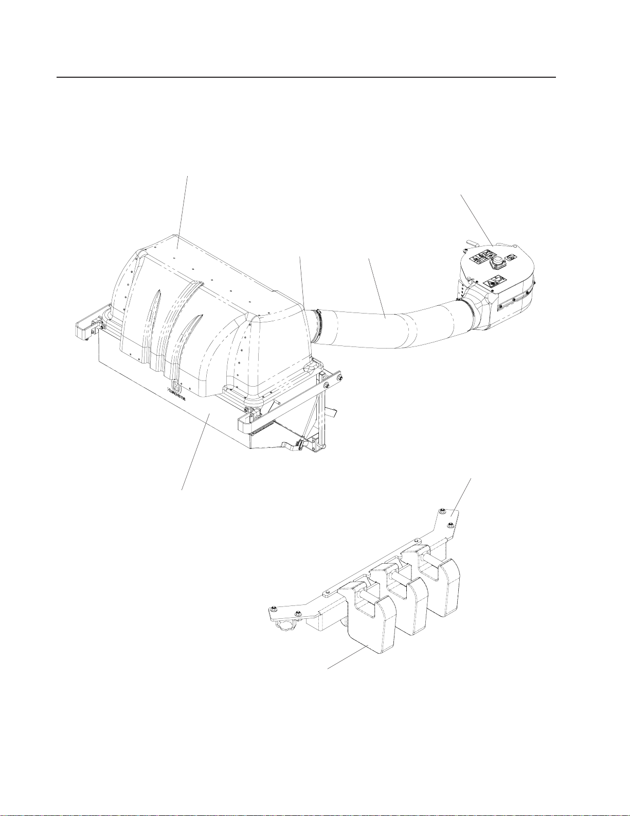
FEATURES & CONTROLS
HOOD
BLOWER ASEMBL Y
HOPPER
INLET
HOSE
WEIGHT BAR
CAST WEIGHT
NOTE: Your Front Weight Bar may look different from those shown in this diagram.
4

SAFETY RULES
General Information
This manual will assist you in the safe operation
and proper maintenance of your Husqvarna
equipment. Read it thoroughly before attempting
to operate the machine. Call your dealer or
Husqvarna if additional information is required.
The following safety symbols are used throughout
the manual to alert you to information about unsafe
actions or situations:
DANGER indicates immediate hazards that
may result in severe injury or death.
WARNING indicates unsafe actions or
situations that may cause severe injury,
death, and/or major equipment or property
damage.
CAUTION indicates unsafe actions or
situations that may cause injury and/or
minor equipment or property damage.
This equipment should not be modified without the
manufacturer’s prior written authorization. Doing
so may not only affect the equipments’
performance and durability , but also create safety
hazards for the operator and the surroundings.
Warranty will be void if changes are made to the
equipment without the manufacturer’s prior written
authorization.
Safety Procedures
1 - Training:
• Read the Operator’s manual. If the operator(s)
or mechanic(s) can not read English it is the
owner’s responsibility to explain this material to
them.
• Become familiar with the safe operation of the
equipment, operator’s controls, and safety
signs.
• All operators and mechanics should be trained.
The owner is responsible for training the users.
• Never let children or untrained people operate
or service the equipment. Local regulations may
restrict the age of the operator.
• The owner/user can prevent and is responsible
for accidents or injuries occurring to themselves,
other people, and/or property.
2 - Preparation:
• Wear appropriate clothing including hard hat,
safety glasses and ear protection. Long hair,
loose clothing or jewelry may get tangled in
moving parts.
• Inspect the area where the equipment is to be
used and remove all objects such as rocks, toys
and wire which can be thrown by the machine.
• Use extra care when handling gasoline and
other fuels. They are flammable and vapors
are explosive. Use only an approved container.
Never remove gas cap or add fuel with engine
running. Allow engine to cool before refueling.
Do not smoke while fueling or operating
equipment. Never refuel or drain the machine
indoors.
• Check that operator’s controls, safety switches,
hoses, and shields are securely attached and
functioning properly. Do not operate unless
they are functioning properly .
5

SAFETY RULES
3 - Operation
• Never run an engine in an enclosed area.
• Only operate in good light, keeping away from
holes and hidden hazards.
• Slow down and use extra care on hillsides.
Make turns gradually and at slow speed. Do
not operate across the sides of slopes. Operate
up and down slopes only. Do not operate on
steep slopes.
• Turf conditions can affect the machine’ s stability .
Do not operate on wet grass where traction may
be reduced.
• Do not change the engine governor setting or
overspeed the engine.
• Stop equipment and inspect vacuum impeller
and hoses after striking objects or if an abnormal
vibration occurs. Make necessary repairs before
resuming operations.
• Look behind and down before backing up to
ensure a clear path.
• Slow down and use caution when making turns
and crossing roads and sidewalks. Stop vacuum
and mower blades if not mowing.
• Do not operate machine under the influence of
alcohol or drugs.
• Use care when loading or unloading the machine
into a trailer or truck.
• Use care when approaching blind corners,
shrubs, trees, or other objects that may obscure
vision.
4 - Maintenance and Storage:
• Stop engine and disconnect spark plug wire.
Wait for all movement to stop before adjusting,
cleaning, or repairing.
• Clean grass and debris from muffler and engine
to help prevent fires. Clean up oil or fuel
spillage.
• Let engine cool before storing and do not store
near sparks or open flame.
• Shut off fuel while storing. Do not store fuel
near flames or drain indoors.
• Never allow untrained personnel to service
machine.
• Keep hands and feet away from moving parts.
If possible, do not make adjustments with the
engine running.
• Keep all parts in good working condition and all
hardware tightened. Replace all worn or
damaged decals.
6
ASSEMBLY
Assembly Instructions
For iZ Models with a Kawasaki
engine and vertical muffer only.
You must obtain a muffler kit Part No.
539 113780, from your dealer prior to installing the collection system.
1. Remove old muffler from unit. Clean engine exhaust flange of any residual gasket material.
2. Remove hardware on upper right guard
on the engine shield and retain.
3. Remove hardware from the upper right
guard on the unit and retain.
4. Install new muffler with new gaskets provided.
ENGINE SHIELD
REMOVE HARDWARE
5. Slide right guard to second set of holes
attach with original hardware.
6. Reattach the right guard to the unit. Place
the spacers on the inside of the frame,
secure with original hardware.
See illustration.
REPLACE SPACER T O
INSIDE
UPPER RIGHT
GUARD
REMOVE HARDWARE
7
ASSEMBLY
Assembly Instructions
Front Weight Bar For iZ Models
Tools Required:
Ratchet with 5/16” Socket
5/16” Wrench
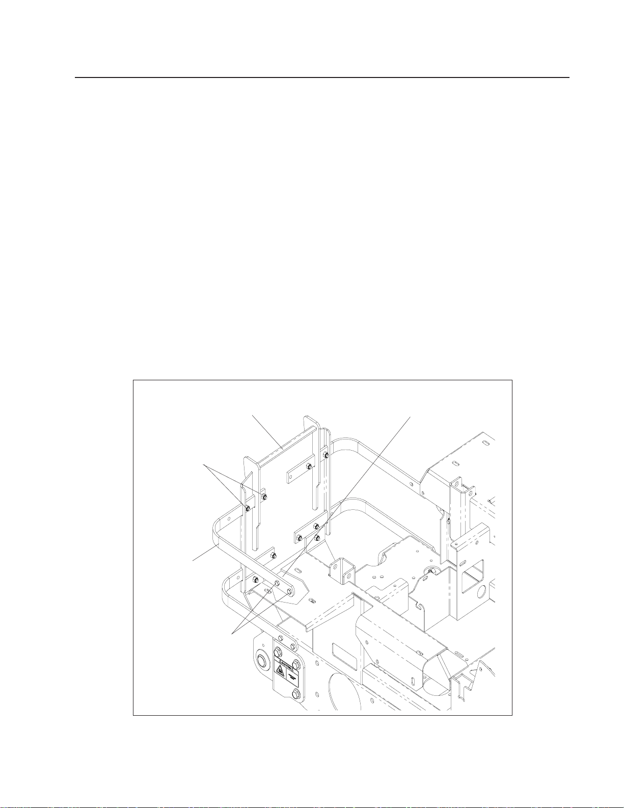
Mounting Instructions
• Remove mower foot plate and floor pan.
• Align weight bar to the front of the frame. See diagram.
• Secure weight bar to mower frame with four 5/16-18 x 1 1/4” hex bolts from kit, reuse the
four 5-16” washers and four 5/16” nyloc nuts that were removed from the foot plate.
• Place all front weights on front weight bar.
• Place holddown bar over front weights and secure to front weight bar using two 3/8” x 1”
clevis pins and two hair pins.
• Reinstall floor pan.
FRONT WEIGHT BAR
WEIGHT BAR HOLD DOWN
CAST COUNTERWEIGHT
8
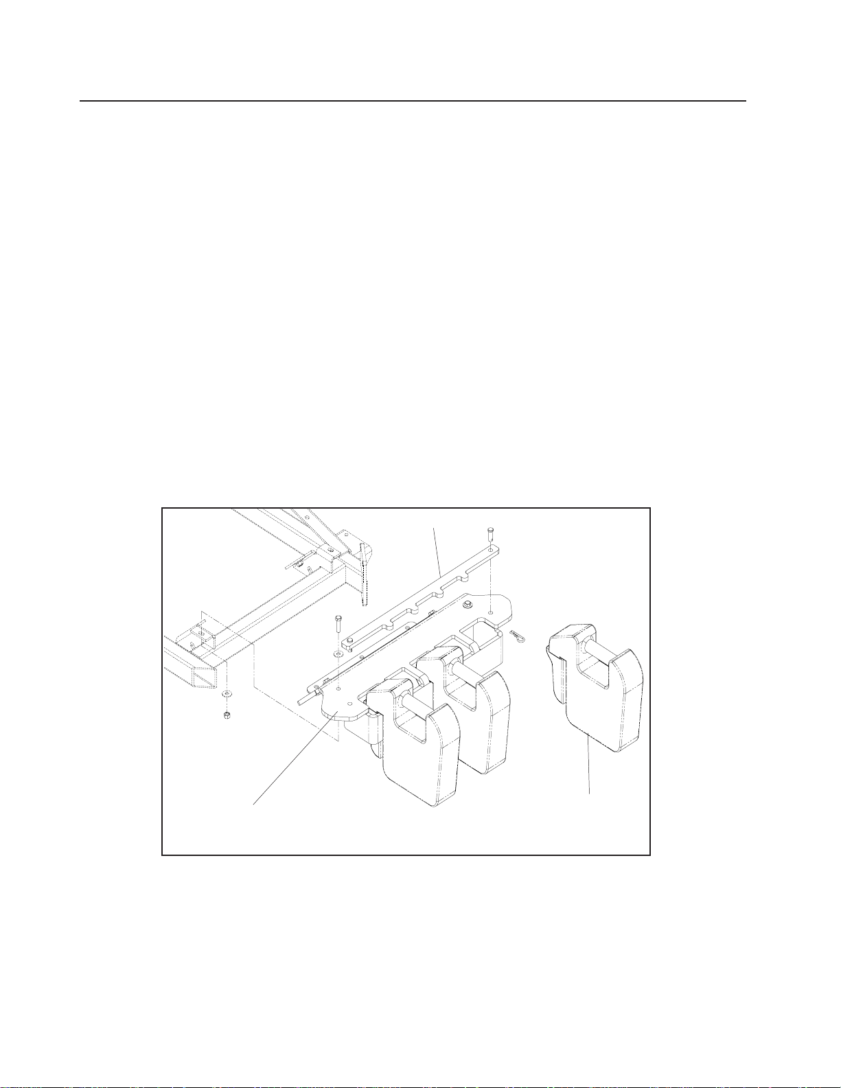
ASSEMBLY
Assembly Instructions
Front Weight Bar For LZ Models
Tools Required:
Ratchet with 3/8” Socket
3/8” Wrench
Mounting Instructions
• Using the weight keepers, attach front weight bar to mower at the front caster arms.
See diagram.
• Secure front weight bar to mower frame with four 3/8” x 1 1/4” hex bolts, four 3/8” flat washers,
and four 3/8” nyloc nuts.
• Place all front weights on front weight bar.
• Place holddown bar over front weights and secure to front weight bar using two 3/8” x 1” clevis
pins and two hair pins.
CAST COUNTERWEIGHT
WEIGHT BAR HOLD DOWN
FRONT WEIGHT BAR
9
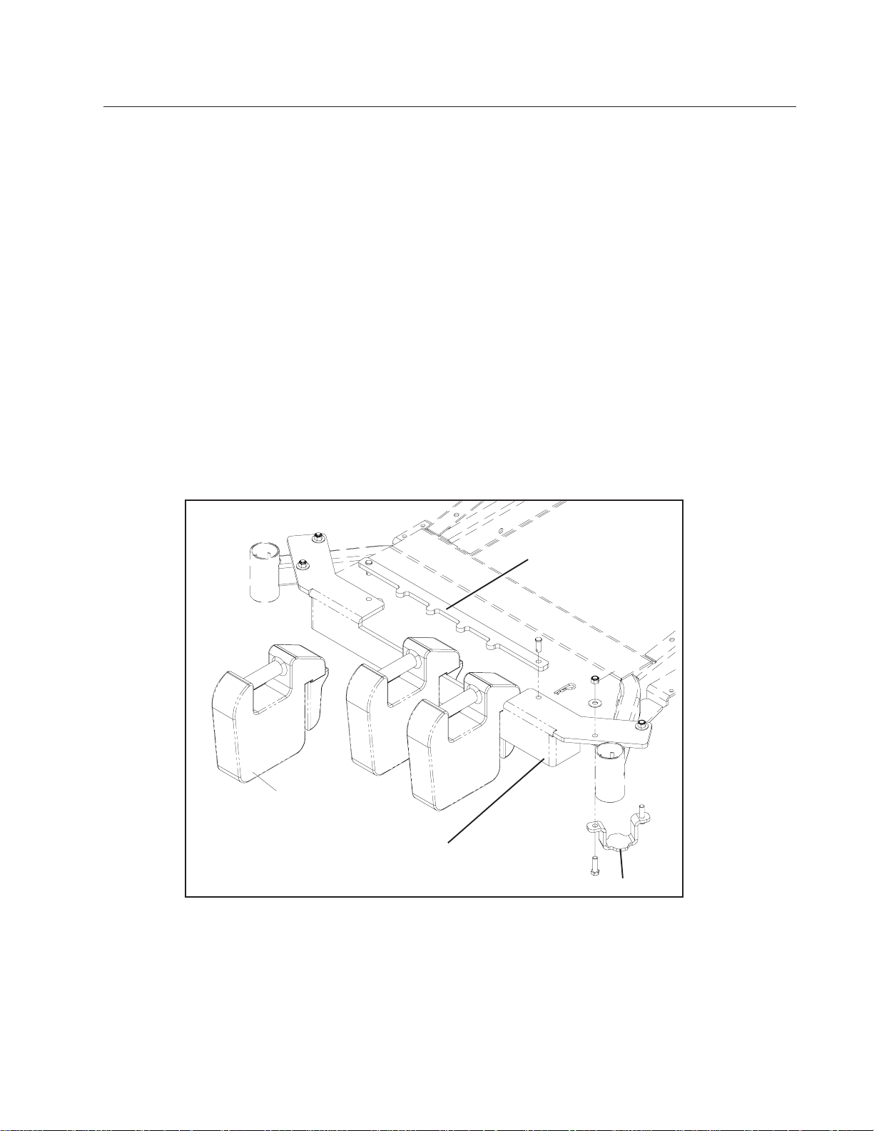
Assembly Instructions
Collection System
Tools Required:
ASSEMBLY
SUPPORT BRACKET
Ratchet
Torque Wrench
1/2" Wrench
1/2" Socket
9/16" Wrench
9/16" Socket
5/8" Socket
(2) 3/4" Wrench
3/4" Socket
Flat Screw Driver
5/32" Allen Wrench
Hacksaw
11/32" Drill Bit
Drill
1. Open the mounting kit box and remove all of
the components.
2. Place the support bracket on the frame and
secure with (2) 990563, 3/8 x 1 bolts and (2)
976979, 3/8 nyloc nuts. Figure 1.
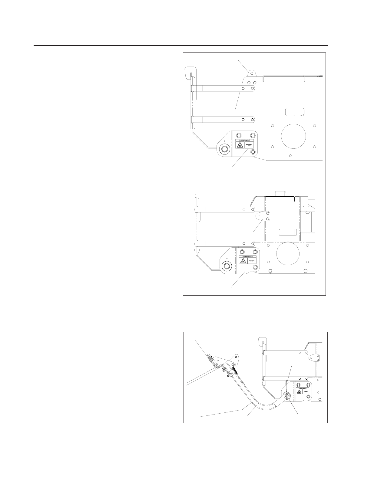
3. Place the hitch brackets on the frame and
secure with (3) 990622, 1/2 x 1 1/4 bolts and
(3) 101331, 1/2 nyloc nuts. Figure 1.
HITCH BRACKET
LZ MODLES
SUPPORT BRACKET
4. Place the hitch assembly on the ground
behind the mower. Place the (2) hitch pins
thru the hitch and the hitch brackets. Secure
the hitch pins with the (2) hairpins that are
secured with the (2) lanyards. Figure 2.
HITCH BRACKET
10
FIGURE 1
HITCH ASSEMBL Y
FIGURE 2
iZ MODLES
LANY ARD
HITCH PIN
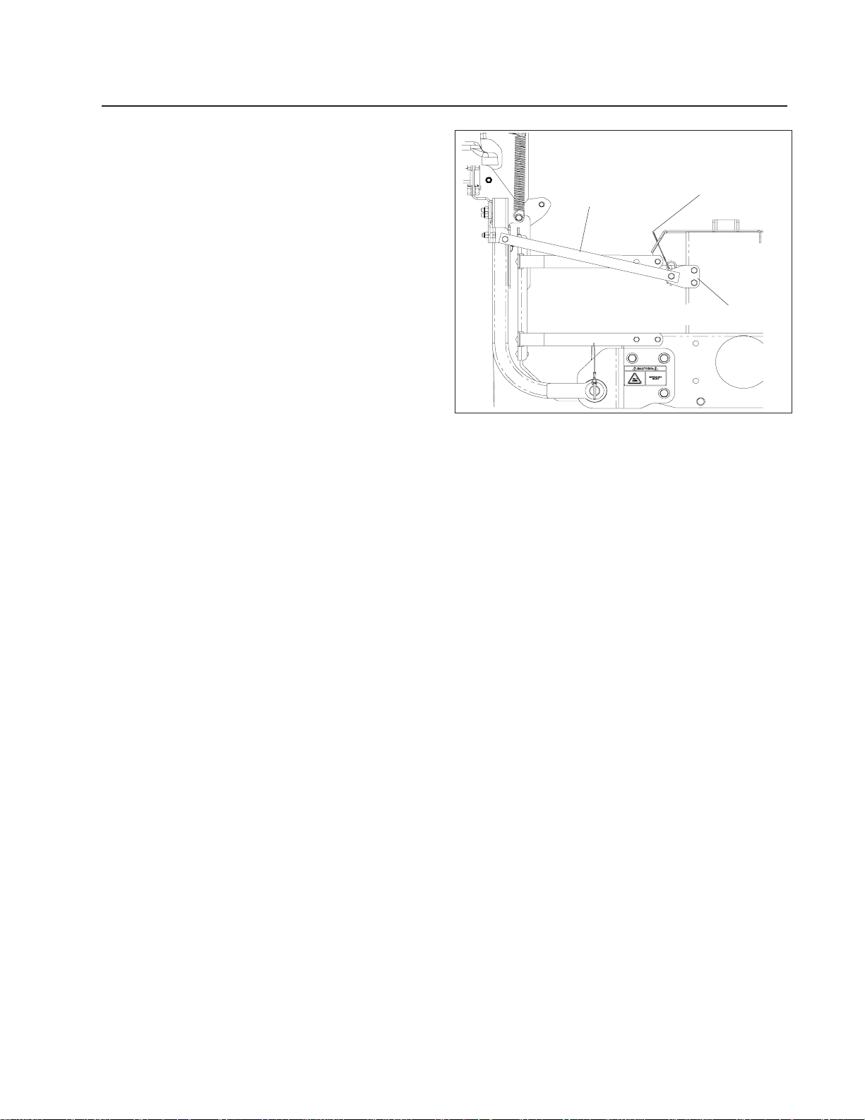
ASSEMBLY
5. Install the two (2) strapes with 1/2” bolts and
nuts on the hopper and install the two (2)
support brackets on the frame.
6. Attach hose support rod to the right side of
the unit to keep the right rear tire from
rubbing the hose.
STRAP
FIGURE 3
LANYARD
SUPPORT BRACKET
11
 Loading...