

Husqvarna DM 330 User Manual

GB
Operator’s manual
Please read the operator’s manual carefully and make sure you understand the instructions before using the machine.
ES
PT
GR
Manual de instrucciones
Lea detenidamente el manual de instrucciones y asegúrese de entender su contenido antes de utilizar la máquina.
Instruções para o uso
Leia as instruções para o uso com toda a atenção e compreenda o seu conteúdo antes de fazer uso da máquina.
√‰ËÁ›Â˜ ¯Ú‹Ûˆ˜
¢И·Я¿ЫЩВ ЪФЫВОЩИО¿ ЩИ˜ √‰ЛБ›В˜ ¯Ъ‹ЫВˆ˜ О·И О·Щ·УФ‹ЫЩВ ЩФ ВЪИВ¯fiМВУФ
ЪИУ ¯ЪЛЫИМФФИ‹ЫВЩВ ЩФ МЛ¯¿УЛМ·.
DM 330
GGGGBBBB EEEESSSS PPPPTTTT GGGGRR
RR
KEY TO SYMBOLS
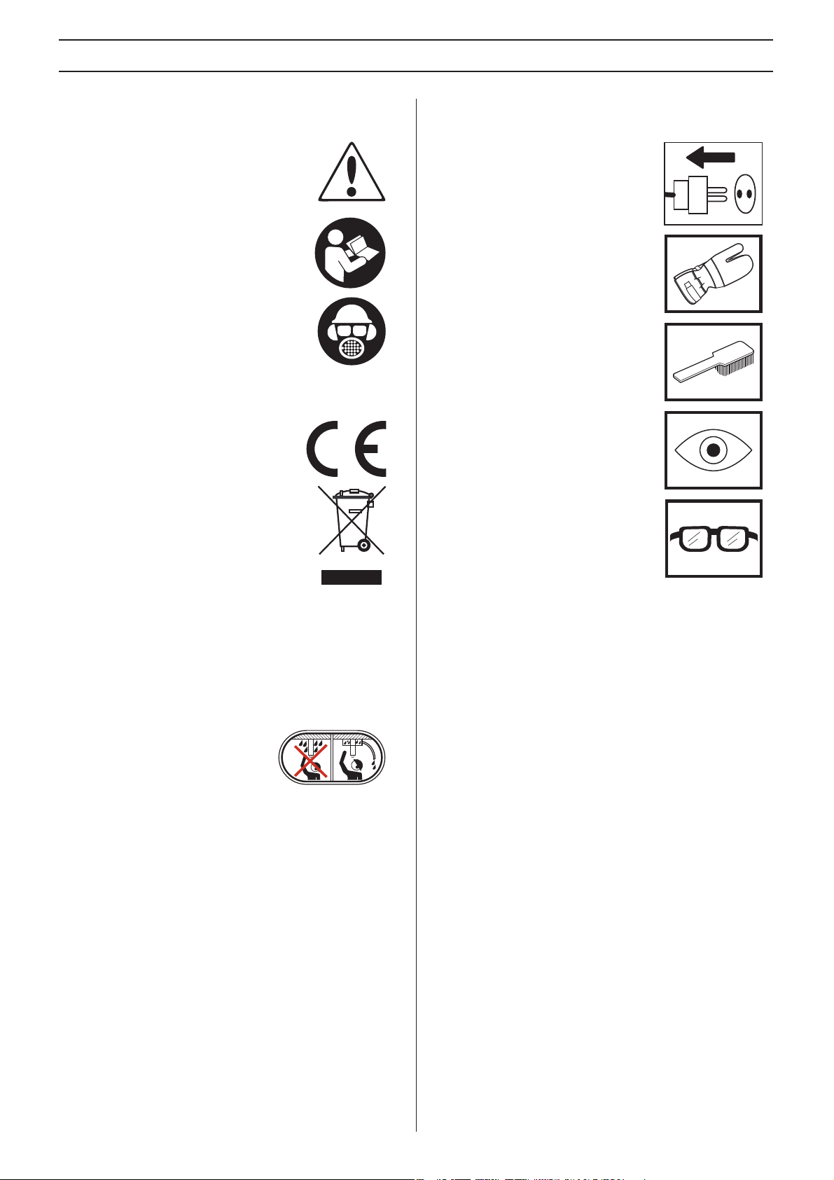
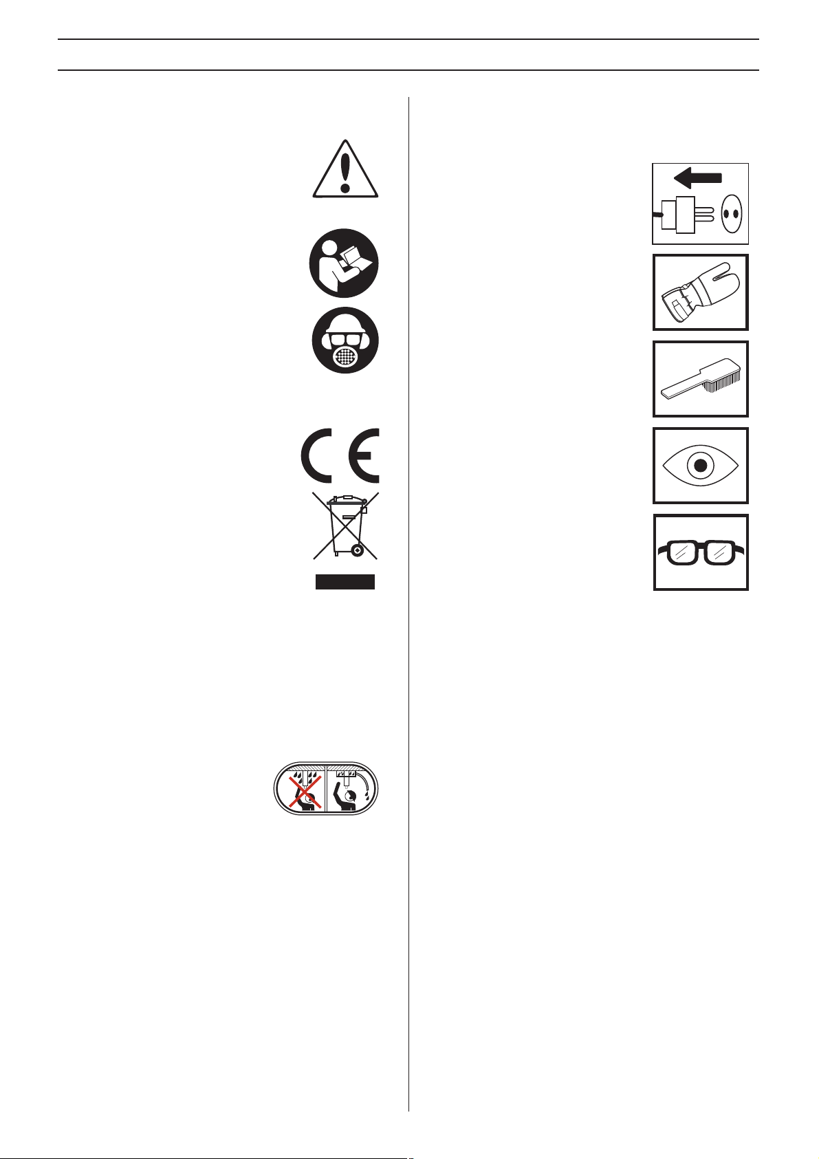
Symbols on the machine:
WARNING! The machine can be a
dangerous tool if used incorrectly or
carelessly, which can cause serious or fatal
injury to the operator or others.
Please read the operator’s manual carefully
and mak
instructions before using the machine.
Always wear:
• Approved protective helmet
• Approved hearing protection
• Protective goggles or a visor
• Breathing mask
This product is in accordance with
applicab
Environmental marking. Symbols on the
product or its packaging indicate that this
product cannot be handled as domestic
waste. It must instead be submitted to an
appropriate recycling station for the recovery
of electrical and electronic equipment.
By ensuring that this product is taken care of
correctly
potential negative impact on the environment and people that
can otherwise result through the incorrect waste
management of this product.
For more detailed information about recycling this product,
contact y
shop from where you purchased the product.
e sure you understand the
le EC directives.
, you can help to counteract the
our municipality, your domestic waste service or the
Symbols in the operator’s manual:
Inspection and/or maintenance should
be carried out with the motor switched
off and the plug disconnected.
Always wear approved protective
glo
ves.
Regular cleaning is required.
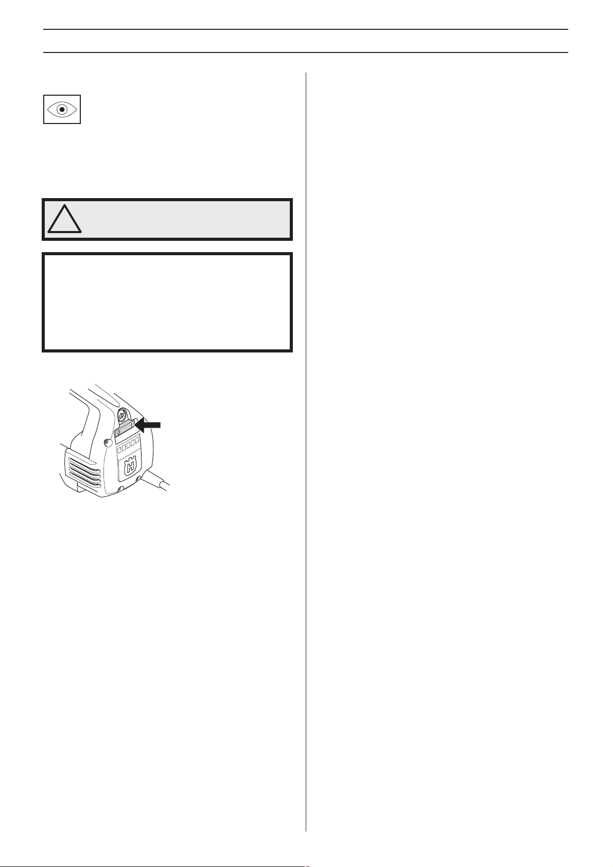
Visual check.
Protective goggles or a visor must be
worn.
Ensure that water cannot leak into the
machine when dr
Use an appropriate water collector.
Other symbols/decals on the
machine refer to special
certification requirements for certain markets.
illing in the ceiling.
2 – English

CONTENTS
Contents
KEY TO SYMBOLS
Symbols on the machine: ............................................. 2
Symbols in the operator’s manual: ............................... 2
CONTENTS
Contents ...................................................................... 3
PRESENTATION
DM 330 ........................................................................ 4
WHAT IS WHAT?
What is what on the drilling machine? ......................... 5
SAFETY INSTRUCTIONS
Steps before using a new drilling machine .................. 6
Personal protective equipment ..................................... 6
General safety precautions .......................................... 7
General working instructions ....................................... 8
Machine
STARTING AND STOPPING
Before starting ............................................................. 10
Starting ........................................................................ 10
Stopping ....................................................................... 10
MAINTENANCE
General ........................................................................ 11
Changing the drill bit .................................................... 11
Cleaning ....................................................................... 11
Electrical Feed ............................................................. 11
Changing the gearbox oil ............................................. 11
Replacing the carbon brushes ..................................... 12
Replacing the seal retainer .......................................... 12
Daily maintenance ....................................................... 12
Repairs ........................................................................ 12
TECHNICAL DATA
EC-declaration of conformity ........................................ 14
WIRING DIAGRAM
′s safety equipment ........................................ 9
English – 3

PRESENTATION
DM 330
It is our wish that you will be satisfied with your product and
that it will be your companion for a long time. Think of this
operator′s manual as a valuable document. By following its′
content (using, service, maintenance etc) the life span and
the second-hand value of the machine can be extended. If
you will sell this machine, make sure that the b uyer will get the
operator′s manual.
A purchase of one of our products gives you access to
essional help with repairs and services. If the retailer who
prof
sells your machine is not one of our authorised dealers, ask
him for the address of your nearest service workshop.
Husqvarna Construction Products has a policy of continuous
product de
the design and appearance of products without prior notice
and without further obligation introduce design modifications.
• DM 330 is an electric stand drill, intended for drilling holes
• The drilling machine has a modular design and is easy to
• The machine is equipped with a water connection which
• DM 330 has three speed ranges for drill sizes up to 350
• The machine has a water cooled gearbox with a pipe that
• The machine is equipped with LEDs which indicate the
The drilling machine is equipped with Softstart
SmartstartTM, ElgardTM and speed control.
velopment. Husqvarna reserves the right to modify
in concrete
assemb
can be rotated 180 deg
mm on the lo
speed version.
uns through the spindle.
r
wer output. This way you can always get maximum
po
power output without damaging the machine.
, bricks and various stone materials.
le.
rees to facilitate work.
w speed version and 250 mm on the high
TM
,
Softstart
SoftstartTM is an electronic current limiter which provides a
softer start. Maximum speed is reached about three seconds
after the machine is turned on.
Smartstart
If the SmartstartTM button is pressed in the speed is reduced.
In SmartstartTM mode the machine has less power until the
button is pressed in again. These functions are of great use
for creating a pilot hole for drilling.
Elgard
ElgardTM is an electronic overload protection. It considers
factors such as rated input voltage and ambient temper ature.
This way you can alw a ys get maxim um po wer output without
damaging the machine.
If the motor is overloaded, the overload protection pulses the
motor
speed. The overload protection disconnects the power, if the
machine is subjected to heavy loads or if the drill bit jams.
Reset the machine by switching it off and then on again. If the
drill bit jams, the mechanical slip clutch protects the gearbox
before the overload protection disconnects the power.
TM
TM
TM
. Reduce the load and the motor returns to its normal
Speed control
The speed control function provides the machine with a
limited idling speed. This provides a more effectiv e cooling of
the machine at idle speed.
Ergonomics
The carrying handle makes it easy to carry/transport the
machine and facilitates mounting it on the stand.
4 – English
WHAT IS WHAT?
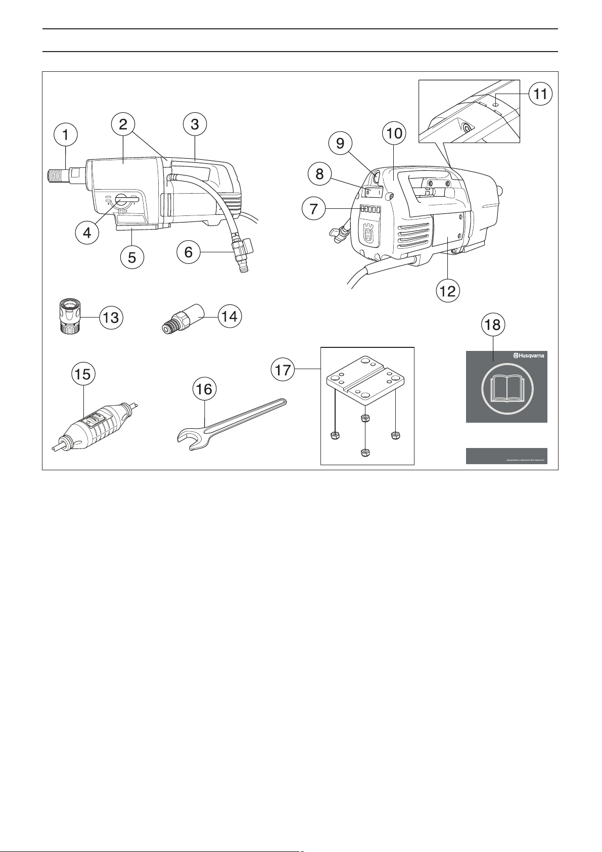
What is what on the drilling machine?
1 Drill spindle
2 Gearbox and motor module
3 Carrying handle
4 Gear knob
5 Quick mount, for Husqvarna stand
6 Water connector
7 LEDs for indicating power output
8 Switch
9 Smartstart
TM
10 Inspection cover
11 Leakage hole
12 Inspection hatch
13 Junction coupling (accessory)
14 Adapter (accessory)
15 Ground fault circuit interrupter (not for GB)
16 Open-ended spanner, 32 mm
17 Engine mount, stand
18 Operator
′s manual
English – 5
SAFETY INSTRUCTIONS
Steps before using a new drilling machine
• Do not use the drilling machine without first reading and
understanding the contents of this Operator’s Manual.
• DM 330 is an electric stand drill, intended for drilling holes
in concrete
• The machine is intended for use in industrial applications
y experienced operators. Use in any other way is
b
considered as contrary to the intended use.
Always use common sense
It is not possible to cover e v ery conceivable situation y ou can
face when using a drilling machine. Alwa ys ex ercise care and
use your common sense. Avoid all situations which you
consider to be beyond your capability. If you still feel uncertain
about operating procedures after reading these instructions,
you should consult an expert before continuing. Do not
hesitate to contact your dealer or us if you have any more
questions about the use of the drilling machine. We will
willingly be of service and provide you with advice as well as
help you to use your drilling machine both efficiently and
safely.
Let your Husqvarna dealer check the drilling machine
regular
Husqvarna Construction Products has a policy of continuous
product de
the design and appearance of products without prior notice
and without further obligation introduce design modifications.
All information and all data in the Operator’s Manual were
applicab
, bricks and various stone materials.
ly and make essential adjustments and repairs.
velopment. Husqvarna reserves the right to modify
le at the time the Operator’s Manual w as sent to print.
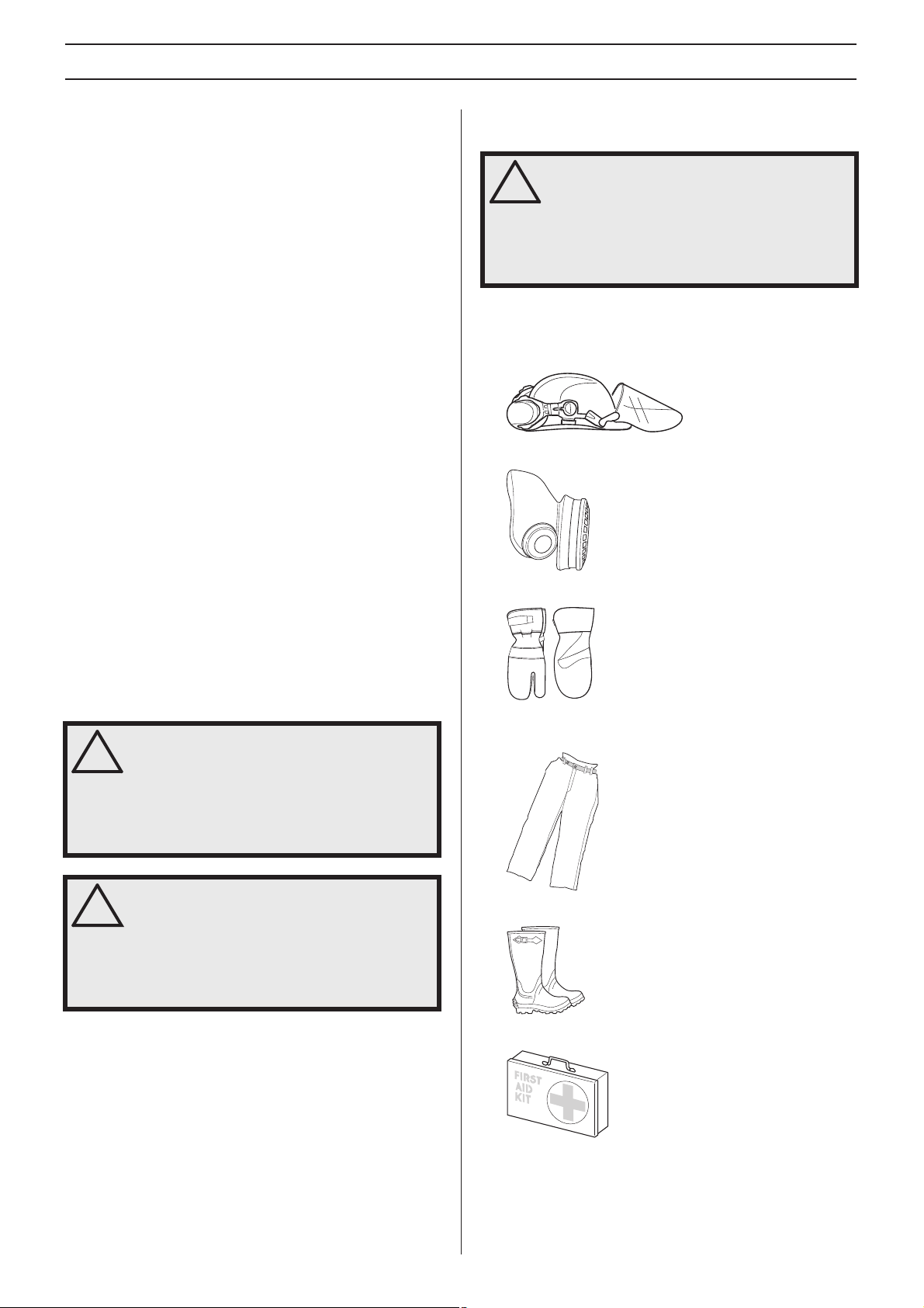
Personal protective equipment
WARNING! You must use approved personal
protective equipment whenever you use the
!
machine. Personal protective equipment
cannot eliminate the risk of injury but it will
reduce the degree of injury if an accident
does happen. Ask your dealer for help in
choosing the right equipment.
• Protective helmet
• Hearing protection
• Protective goggles or a visor
• Breathing mask
• Heavy-duty, firm grip gloves.
WARNING! Under no circumstances should
you modify the original design of the
!
machine without approval from the
manufacturer. Always use original spare
parts. Unauthorized modifications and/or
accessories may lead to serious injury or
death to the user or others.
WARNING! The use of products such as
cutters, grinders, drills, that sand or form
!
material can generate dust and vapours
which may contain hazardous chemicals.
Check the nature of the material you intend
to process and use an appropriate breathing
mask.
• Tight-fitting, heavy-duty and comfortable clothing that
mits full freedom of movement.
per
• Boots with steel toe-caps and non-slip sole.
• Always have a first aid kit nearby.
6 – English

SAFETY INSTRUCTIONS
General safety precautions
WARNING! Read all safety warnings and all
instructions. Failure to follow the warnings
!
and instructions may result in electrtic
shock, fire and/or serious injury.
Work area safety
• Keep work area clean and well lit. Cluttered or dark areas
invite accidents.
• Do not operate power tools in explosive atmospheres,
such as in the presence of flammab
dust. P o wer tools create sparks which may ignite the dust
or fumes.
• People and animals can distract you causing you to lose
control of the machine
concentrated and focused on the task.
• Do not use the machine in bad weather, such as dense
og, heavy rain, strong wind, intense cold, etc. Working in
f
bad weather is tiring and can lead to dangerous
conditions, e.g. slippery surfaces.
• Never start to work with the machine before the working
area is clear and y
obstacles with unexpected movement. Ensure that no
material can become loose and fall, causing injury when
operating the machine.
• Always check the rear side of the surface where the drill
bit will emerge when dr
cordon off the area and make sure that no one can be
injured or material damaged.
. For this reason, always remain
ou have a firm foothold. Look out for an y
illing right through. Secure and
Electrical safety
WARNING! There is always a risk of shocks
from electrically powered machines. Avoid
!
unfavourable weather conditions and body
contact with lightning conductors and metal
objects. Alwa ys follow the instructions in the
Operator’s manual to avoid damage.
WARNING! Do not wash the machine with
water, as water can enter the electrical
!
system or the engine and cause damage to
the machine or short circuit.
• The machine should be connected to an earthed outlet
socket.
• Check that the mains voltage corresponds with that stated
on the r
• Check that the cord and extension cord are intact and in
good condition.
outdoor use.
• Never use the machine if any cable or plug is damaged,
b
• Do not use an extension cord while it is rolled up to av oid
o
ating plate on the machine.
Use an extension cord intended for
ut hand it in to an authorized service workshop for repair.
verheating.
le liquids, gases or
• Never carry the machine by means of the cord and ne v er
pull out the plug b
• Keep all cords and extension cords away from water, oil
and shar
doors, fences or the like . Otherwise it can cause the object
to become live.
• The water system cools the drill bit with clean water. The
po
what is provided by the water system. Make sure that no
drill slurry enters the machine.
• Do not expose the power tool to rain. Water entering a
po
• Ensure the cord is behind you when you start to use the
machine so that the cord will not be damaged.
!
p edges. Make sure the cord is not pinched in
wer tool should not be exposed to more moisture than
wer tool will increase the risk of electric shock.
WARNING! The machine (Great Britain 120V)
is not equipped with a ground fault circuit
interrupter. The machine must always be
used with an isolating transformer for
protection in case an electrical fault should
occur.
y pulling the cord.
Personal safety
• Wear personal protective equipment. See instructions
under the heading ”Personal protective equipment”.
• Never use the machine if y ou are tired, if you have drunk
alcohol, or if y
your vision, your judgement or your co-ordination.
• Prevent unintentional starting. Ensure the switch is in the
OFF-position bef
Carrying power tools with your finger on the switch or
energising power tools that have the switch on invites
accidents.
• Remove any adjusting key or wrench before turning the
wer tool on. A wrench or a k ey left attached to a rotating
po
part of the power tool may result in personal injury.
• Never allow anyone else to use the machine without first
ing that they have understood the contents of the
ensur
operator’s manual.
• Be careful as clothing, long hair, and jewellery can get
caught in mo
• Remain at a distance from the drill bit when the motor is
unning.
r
• Make sure that no pipes or electrical cables are routed in
the area to be dr
• Never leave the machine unsupervised with the motor
unning.
r
• Always unplug the machine during longer work breaks.
• Never work alone, alw a ys ensure there is another person
close at hand. Apart from being able to receive help to
assemble the machine, you can also get help if an
accident should occur.
ou are taking medication that could affect
ore connecting to power source.
ving parts.
illed.
English – 7
SAFETY INSTRUCTIONS
Use and care
• Never use a machine that is faulty. Carry out the checks,
maintenance and service instructions described in this
manual. Some maintenance and service measures must
be carried out by trained and qualified specialists. See
instructions under the heading Maintenance.
• Inspection and/or maintenance should be carried out with
the motor s
• Do not use the power tool if the switch does not turn it on
and off
switch is dangerous and must be repaired.
• Never use a machine that has been modified in any way
from its or
• Do not overload the machine. Overloading can damage
the machine
• Keep tools sharp and clean in order to enable safer work.
• Keep all parts in good working order and ensure that all
fixtures are proper
witched off and the plug disconnected.
. An y po w er tool that cannot be controlled with the
iginal specification.
.
ly tightened.
Transport and storage
• Do not store or transport the drilling machine with the drill
bit fitted in order to protect your drilling machine and drill
bits from damage.
• Store the drilling machine in a lockable area so that it is
out of reach of children and unauthor
• Store the drilling machine and stand in dry and frost free
conditions
.
ised persons.
General working instructions
WARNING! This section takes up the basic
safety precautions for working with the
!
drilling machine. This information is never a
substitute for professional skills and
experience. If you encounter a situation
where you are uncertain how to proceed you
should ask an expert. Contact your dealer,
service agent or an experienced drilling
machine user. Do not attempt any task that
you feel unsure of!
• The machine has a very high torque. This demands good
concentration during work, as serious personal injuries
can occur if the drill bit suddenly jams.
• Keep your hands at a safe distance from the drill spindle
ill bit when the machine is running.
and dr
• Keep an eye open for oil or water leakage. If water or oil
ickles out from the leakage hole on the top of the pinion
tr
neck, the seals must be replaced.
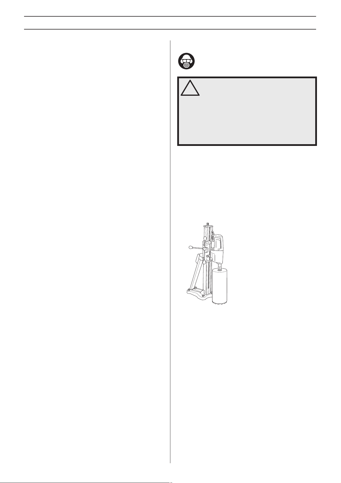
Stand drilling
8 – English
• The machine is intended for stand mounted drilling.
• The following Husqvarna drill stands are recommended
or use with the drill motor:
f
- DS 50 AT/ATS/Gyro/COMBO/BASIC
- DS 70 AT/ATS
- DS 450 ATS
• Make sure that the stand is secured correctly.
• Make sure that the drilling machine is secured correctly in
the stand.
Drilling outdoors
• Always use extension cables that are approved for
outdoor use.
Drilling in ceilings and the like
• Use a water collector to avoid water penetrating into the
machine.
SAFETY INSTRUCTIONS
Machine′′′′s safety equipment
This section describes the machine′s safety equipment, its
purpose, and how checks and maintenance should be carried
out to ensure that it operates correctly. See the ”What is
what?” section to locate where this equipment is positioned
on your machine.
WARNING! Never use a machine that has
faulty safety equipment!
!
IMPORTANT! All servicing and repair work on the machine
requires special training. This is especially true of the
machine′s safety equipment. If your machine fails an y of the
checks described below you must contact your service
agent. When you b uy any of our products we guar antee the
availability of prof essional repairs and service. If the retailer
who sells your machine is not a servicing dealer, ask him for
the address of your nearest service agent.
Switch
The power switch should be used to start and stop the
machine.
Checking the power switch
• Start the machine by switching on the on-off switch.
• Switch the on-off switch off to stop the machine.
• A defective power switch should be replaced by an
authorized service workshop.
English – 9
STARTING AND STOPPING
Before starting
WARNING! Note the following before
starting:
!
The machine should be connected to an
earthed outlet socket.
Check that the mains voltage corresponds
with that stated on the rating plate on the
machine.
Ensure you stand firmly. Keep people and
animals well away from the working area.
Make sure that:
• Power switch, cord and electrical outlet are intact. If not,
y must be replaced by an authorised repairman.
the
• Cooling air vents are not blocked.
• The machine and its equipment are correctly installed.
• The stand is properly fixed and that the drill is properly
mounted on the stand.
• The drill is secured properly.
• Water cooling is undamaged and connected to the
machine
• Use suitable drill bits depending on whether water or dry
dr
contact your dealer, your service workshop or an
experienced operator.
• Prevent unintentional starting. Ensure the switch is in the
OFF-position bef
.
illing is being performed. In the event of uncertainty
ore connecting to power source.
Starting
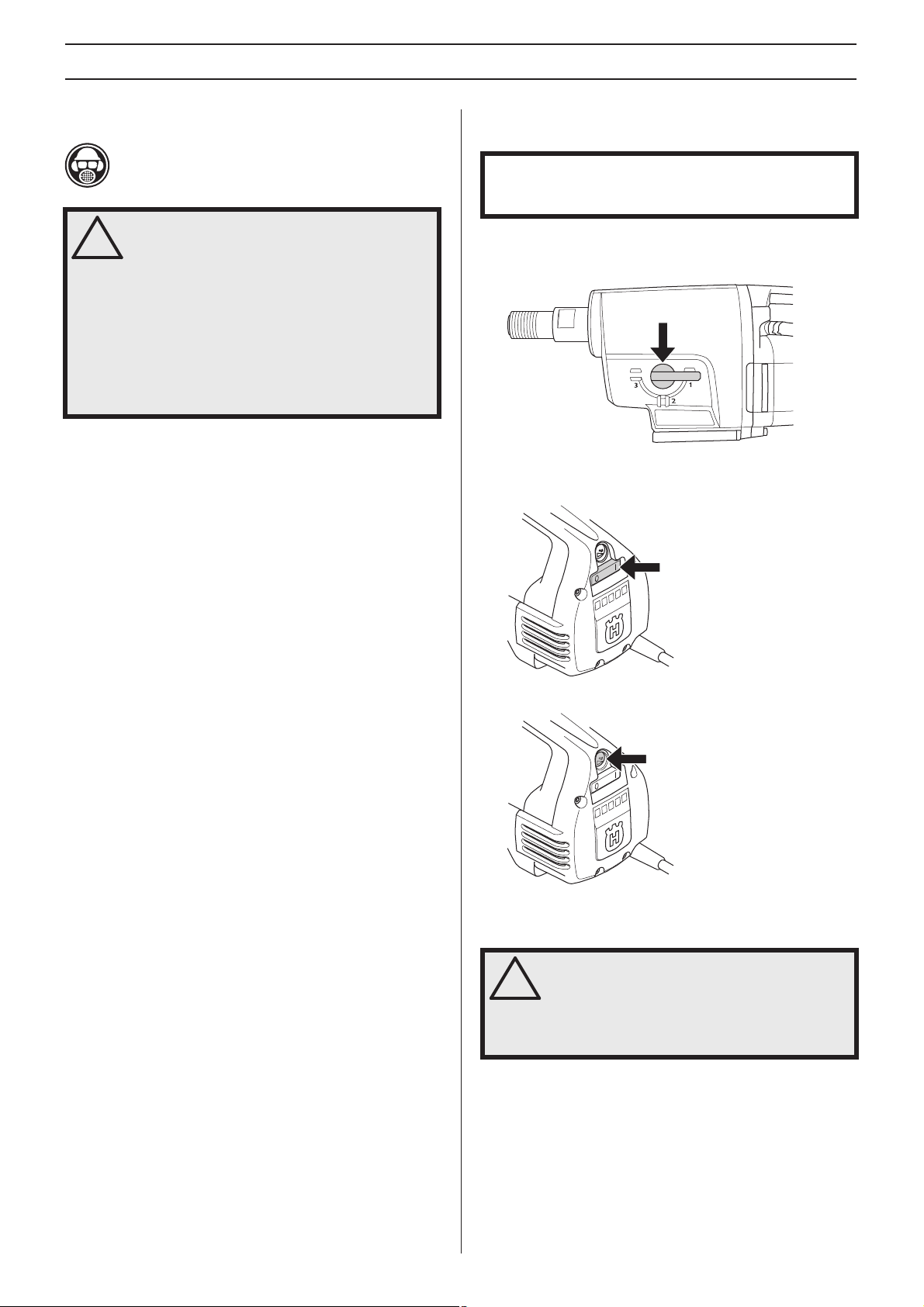
IMPORTANT! Changing gear may only be done when the
machine is switched off. Otherwise there is a risk of
damaging the gearbox.
1 Set the working speed by turning the drill spindle and at
the same time move the gear knob to the required
position.
2 Turn on the water cooling.
3 Start the machine by switching on the on-off switch.
TM
Also press, if desired, the Smartstart
button.
10 – English
Stopping
WARNING! The drill bit continues to rotate
for a while after the motor has been switched
!
off.
Do not stop the drill bit with your hands.
Personal injuries can occur.
Switch the on-off switch off to stop the machine.
Cooling
Run the machine unloaded for a minute or two to cool the
motor.
MAINTENANCE
General
IMPORTANT! Inspection and/or maintenance should be
carried out with the motor switched off and the plug
disconnected.
The lifetime of your machine can be e xtended considerab ly if
it is used, cared for and maintained in the proper manner.
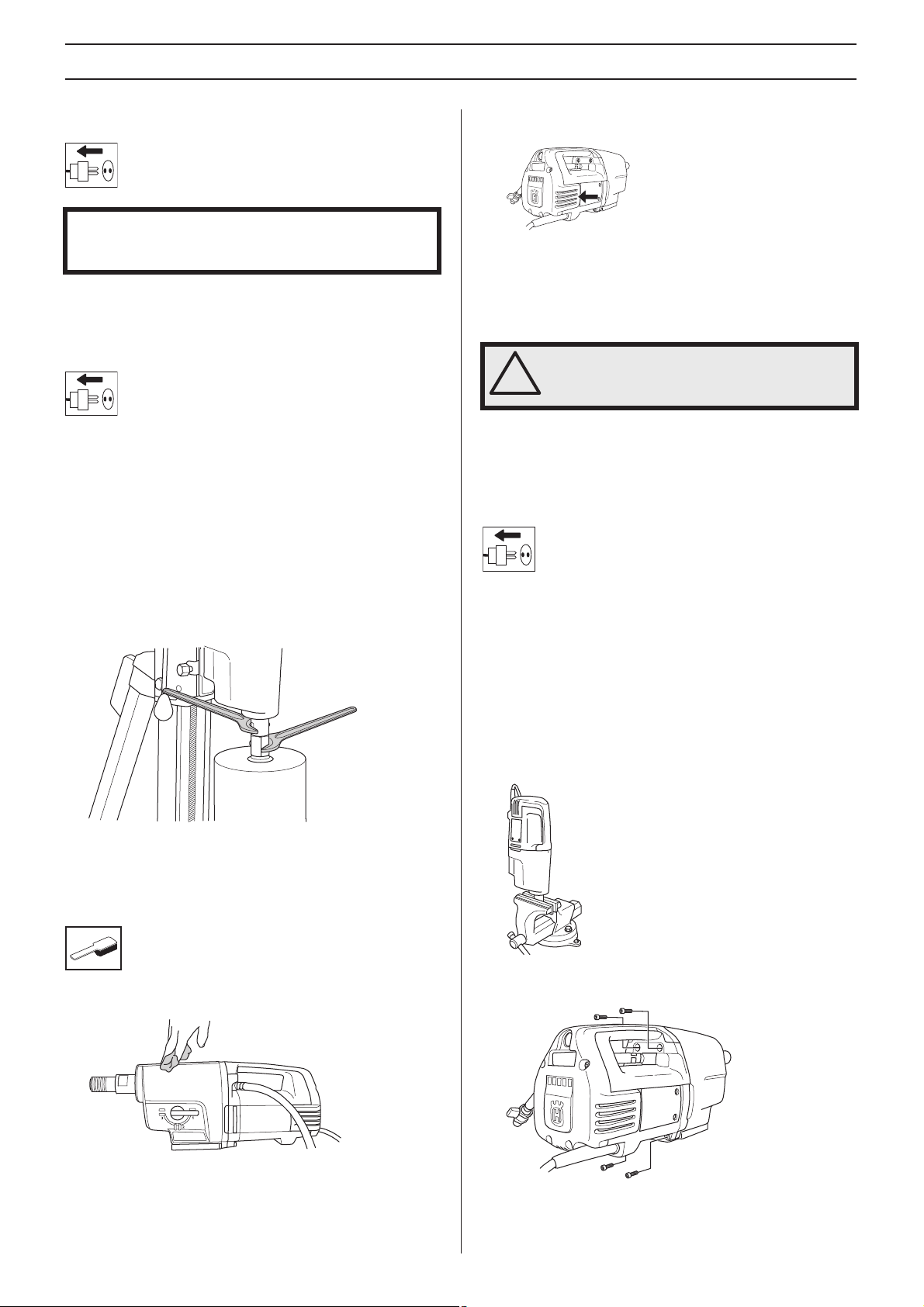
Changing the drill bit
1 Pull out the plug.
2 Get:
- The new drill bit.
- Open-ended spanners, size 24 mm and 32 mm.
- Water-resistant grease.
3 Remove the old drill bit using the open-ended spanners.
4 Apply water-resistant grease to the thread of the new drill
bit.
5 Attach the drill bit using the open-ended spanners.
• In order for the machine to always be cooled sufficiently
the cooling air openings m
• Use compressed air to periodically clean the motor.
Remo
ve the inspection cover and clean the cover.
ust be kept clear and clean.
Electrical Feed
WARNING! Ne ver use dama ged cables. They
can cause serious, even fatal, personal
!
injuries.
Check that the cord and extension cord are intact and in good
condition. Never use the machine if the cord is damaged,
hand it in to an authorized service workshop for repair.
Changing the gearbox oil
Contact your dealer to get the right oil.
The oil in the gearbox must be changed after ev ery 400 hours
ation. Do as follows:
of oper
1 Get:
- New oil, STATOIL SYNTOL 75W-90 or other similar
ansmission oil.
tr
- A container for the old oil.
2 Secure the machine with drill spindle downwards in a vice
or the lik
e.
Before the machine is started, carefully check that the new bit
mly attached.
is fir
Cleaning
• Keep the machine and drill bit clean in order for drilling to
be carried out safely.
• Keep the handle dry and free of grease and oil.
3 Unscrew the four screws holding the motor - gearbox
modules together
4 Carefully disassemble the machine.
5 Empty the gearbox oil into the container.
.
English – 11
MAINTENANCE
6 If necessary contact your dealer to clean the gearbox.
7 Pour the new oil into the gearbox, about 0.5 litres.
8 Check that the sealing lip on the radial seal is intact.
9 Reassemble the machine and screw in the four screws.
Be careful when assemb
radial seal.
ling so as not to damage the
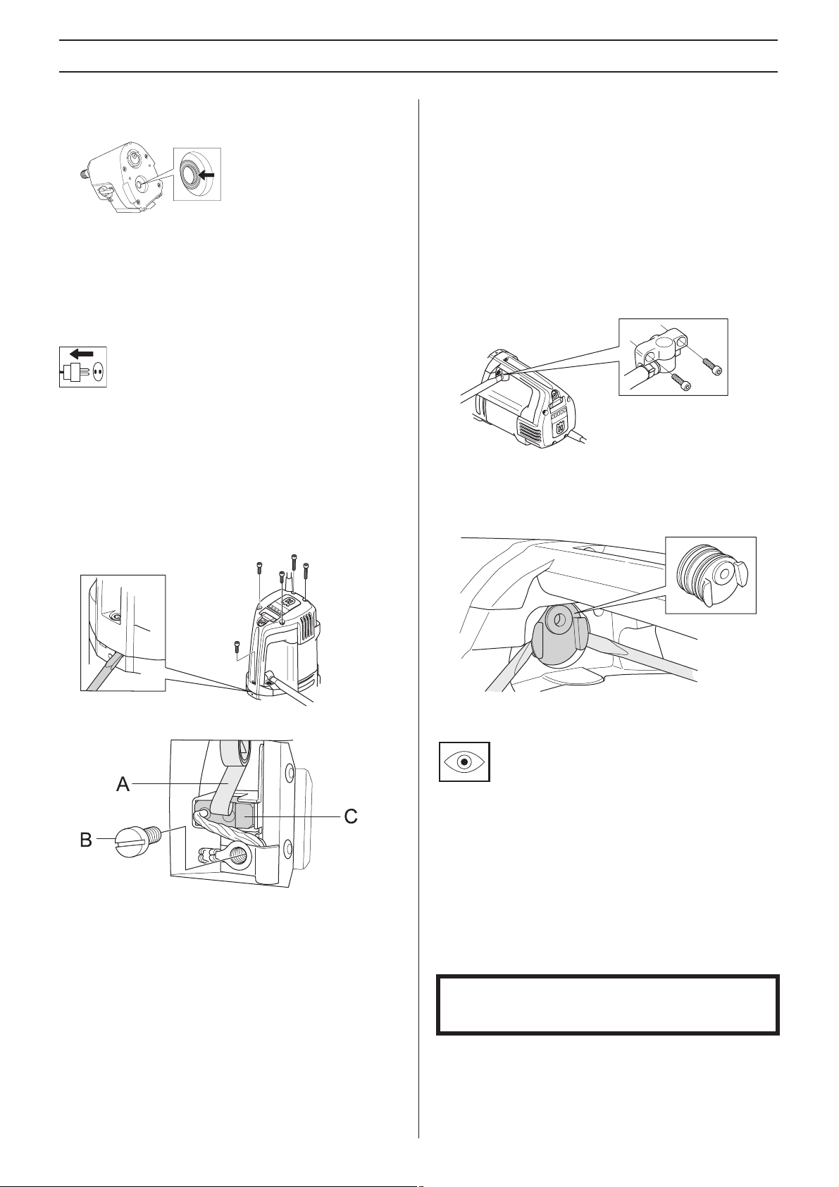
Replacing the carbon brushes
The carbon brushes must be removed and check ed regularly .
Weekly if the machine is used daily or at longer intervals if the
machine is used more seldom. The area of wear should be
even and undamaged.
Both carbon brushes must always be replaced as a pair, but
one at a time
1 Remove the 5 screws from the inspection cover. Use a
chisel in the break tr
cover.
. Do as follows:
acks to easier remove the inspection
10 Repeat the procedure with the other carbon brush.
11 Guide the inspection cover into the handle's tracks . Begin
with the scre
unscrew the inspection cover's five screws.
12 Let the machine idle for 10 minutes to run in the new
carbon br
w at the very bottom of the handle and
ushes.
Replacing the seal retainer
If there is oil or water coming out of the leakage hole the seal
retainer must be replaced.
1 Loosen the two screws for the water module.
2 Use two flathead screwdrivers to carefully prize open the
seal retainer
3 Carefully push in the new seal retainer and screw the
ater module back on.
w
.
2 Lift the carbon brush holder spring to one side (A).
3 Loosen the screw (B).
4 Pull out the carbon brush connector.
5 Pull the carbon brush out from the holder (C).
6 Clean the brush holder with compressed air or a brush.
Replace the br
7 Fit the new carbon brush. Mak e sure that the side with the
copper wire is f
brush slides easily in the brush retainer. If the carbon
brush is fitted in the wrong direction it can get jammed.
8 Put the brush holder spring back into place.
9 Insert the carbon brush connection under the screw.
ush if worn.
acing the gear box and that the carbon
Daily maintenance
1 Check that nuts and screws are tight.
2 Check that the power switch unit works smoothly.
3 Clean the outside of the machine.
4 Check and clean the cooling air openings.
5 Check that the cord and extension cord are intact and in
good condition.
Repairs
Important All types of repairs may only be carried out by
authorised repairmen. This is so that the operators are not
exposed to great risks.
12 – English

TECHNICAL DATA
DM 330
Electric motor Single-phase
Rated voltage, V 230/120
Rated output, W
230V 2700W
120V 2400W
Rated current, A
230V 13A
120V 20A
Weight, kg 13
Max. diameter drill bit, mm/inch
Low speed 350/14
High speed 250/10
Water cooling
Spindle thread G 1 1/4”
Water connector G 1/4”
Water pressure - max, bar 8
Noise emissions (see note 1)
Sound power level, measured dB(A) 112
Sound power level, guaranteed dB(A) 113
Sound levels (see note 2)
Sound pressure level at the operators ear, dB(A) 98
Vibration levels, ahv (see note 3)
Handle, m/s
Note 1: Noise emissions in the environment measured as sound power (LWA) in conformity with EN 12348.
Note 2: Noise pressure level according to EN 12348. Reported data for noise pressure level has a typical statistical dispersion
(standard de
Note 3: Vibration level according to EN 12348. Reported data for vibration level has a typical statistical dispersion (standard
viation) of 1 m/s2.
de
Low speed
Gear
1 250 310 200-350 8-14
2 550 690 100-200 4-8
3 950 1190 50-100 2-4
2
viation) of 1.0 dB(A).
Drill bit speed with
rpm
load,
1,0
Drill bit load without
load, rpm
Recommended drill bit
size, mm
Recommended drill bit
size, inch
High speed
Gear
1 360 450 150-250 6-10
2 800 1000 75-150 3-6
3 1380 1730 25-75 1-3
Drill bit speed with
load, rpm
Drill bit load without
load, rpm
Recommended drill bit
size, mm
Recommended drill bit
size, inch
English – 13

TECHNICAL DATA
EC-declaration of conformity
(Applies to Europe only)
Husqvarna AB, SE-433 81 Göteborg, Sweden, tel: +46-31-949000, declares under sole responsibility that the Husqvarna DM
, from 2010´s serial numbers and onwards (the year is clearly stated in plain text on the rating plate with subsequent serial
330
number), conforms with the requirements of the COUNCIL’S DIRECTIVE:
• of May 17, 2006 "relating to machinery"
• of December 15, 2004 ”relating to electromagnetic compatibility” 2004/108/EC.
• of December 12, 2006 ”relating to electrical equipment”
The following standards have been applied: EN ISO 12100:2003, EN 55014-1:2006, EN 55014-2/A1:2001, EN 61000-3-2:2006,
EN 61000-3-3/A1/A2:2005, EN 12348/A1:2009.
Göteborg December 29, 2009
Henric Andersson
Vice President, Head of Power Cutters and Construction Equipment
(Authorized representative for Husqvarna AB and responsible for technical documentation.)
2006/42/EC
2006/95/EC.
14 – English
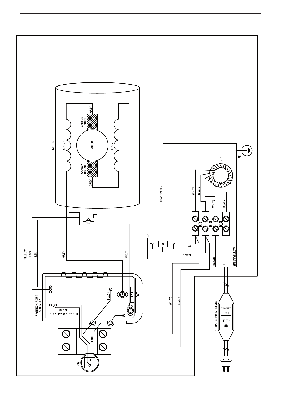
WIRING DIAGRAM
English – 15
ACLARACIÓN DE LOS SÍMBOLOS
Símbolos en la máquina:
¡ATENCIÓN! La máquina, si se utiliza de
forma errónea o descuidada, puede ser una
herramienta peligrosa que puede causar
daños graves e incluso la muerte al usuario
y a otras personas.
Lea detenidamente el manual de
instr
ucciones y asegúrese de entender su
contenido antes de utilizar la máquina.
Utilice siempre:
• Casco protector homologado
• Protectores auriculares homologados
• Gafas protectoras o visor
• Máscara respiratoria
Este producto cumple con la directiva CE
.
vigente
Etiquetado ecológico. El símbolo en el
producto o en su envase indica que no se
puede tratar este producto como desperdicio
doméstico. Deberá por lo tanto depositarse
en un centro de recogida adecuado para el
reciclado de equipos eléctricos y
electrónicos.
Haciendo que este producto sea manipulado
adecuadamente
potenciales para el medio ambiente y las personas, lo que
puede ocurrir con la manipulación inadecuada como residuos
del producto.
Para obtener inf ormación más detallada sobre el reciclado de
este producto
servicio de eliminación de desperdicios domésticos o con la
tienda donde compró el producto.
, se ayuda a evitar consecuencias negativ as
, contacte con la oficina municipal local, con el
Símbolos en el manual de instrucciones:
El control y/o mantenimiento de la
máquina debe hacerse con el motor
parado y el enchufe desenchufado.
Utilice siempre guantes protectores
homologados
La máquina debe limpiarse
regularmente.
Control visual.
Debe utilizarse gafas protectoras o
visor.
.
Al perforar en techo, comprobar que
no puede entr
Utilice un colector de agua adecuado.
Los demás símbolos/etiquetas que
aparecen en la máquina
corresponden a requisitos de homologación específicos
en determinados mercados.
ar agua en la máquina.
16 – Spanish

Índice
ACLARACIÓN DE LOS SÍMBOLOS
Símbolos en la máquina: ............................................. 16
Símbolos en el manual de instrucciones: .................... 16
ÍNDICE
Índice ........................................................................... 17
PRESENTACIÓN
DM 330 ........................................................................ 18
¿QUÉ ES QUÉ?
Componentes de la taladradora ................................... 19
INSTRUCCIONES DE SEGURIDAD
Medidas a tomar antes de utilizar una taladradora
nueva ........................................................................... 20
Equipo de protección personal .................................... 20
Instrucciones generales de seguridad ......................... 21
Instrucciones generales de trabajo .............................. 22
Equipo de seguridad de la máquina ............................ 23
ARRANQUE Y P ARADA
Antes de arrancar ........................................................ 24
Arranque ...................................................................... 24
Parada ......................................................................... 24
MANTENIMIENTO
Generalidades .............................................................. 25
Cambio de broca ......................................................... 25
Limpieza ...................................................................... 25
Suministro eléctrico ..................................................... 25
Cambio del aceite de la caja de cambios .................... 25
Cambio de escobillas de carbón .................................. 26
Cambio del anillo de retención de la junta ................... 26
Mantenimiento diario ................................................... 26
Reparaciones ............................................................... 26
DA TOS TECNICOS
Declaración CE de conformidad .................................. 28
ESQUEMA DE CONEXIONES ELÉCRICAS
ÍNDICE
Spanish – 17

PRESENTACIÓN
DM 330
Esperamos que su máquina le proporcione plena satisfacción
y le sirva de ayuda por mucho tiempo en adelante. Tenga en
cuenta que este manual de instrucciones es un documento
de valor. Siguiendo sus instrucciones (de uso, servicio,
mantenimiento, etcétera) puede alargar considerablemente
la vida útil de la máquina e incrementar su valor de reventa.
Si vende su máquina, entregue el manual de instrucciones al
nuevo propietario.
La adquisición de alguno de nuestros productos da acceso a
asistencia prof
máquina no fue adquirida en un distribuidor oficial, preguntar
en la tienda de compra la dirección del taller de servicio más
cercano.
Husqvarna Construction Products se esfuerza
constantemente por mejor
productos. Por consiguiente, Husqvarna se reserva el
derecho a introducir modificaciones de diseño sin previo
aviso y sin compromisos ulteriores.
• DM 330 es un taladro eléctrico con base diseñado para
perf
• La taladradora es de diseño modular y fácil de montar.
• La máquina está equipada con una conexión hidráulica
que se puede gir
• El taladro DM 330 cuenta con tres velocidades que
miten perforar diámetros de hasta 350 mm a baja
per
velocidad y de 250 mm a alta velocidad.
• La máquina tiene caja de cambios refrigerada por agua
con un tubo que atr
• La máquina tiene LED indicadores que señalan la
potencia de salida.
máxima potencia de salida sin causar daños a la
máquina.
La taladradora está equipada con Softstart
ElgardTM y regulación de velocidad.
esional con reparaciones y servicio. Si la
ar la construcción de sus
orar hormigón, ladrillo y varios tipos de piedra.
ar 180º para facilitar su manejo.
aviesa el eje del husillo.
De esta manera, podrá conseguir la
TM
, SmartstartTM,
Softstart
SoftstartTM es un limitador de sobreintensidad electrónico
que permite un arranque más suave. La velocidad máxima se
alcanza aproximadamente tres segundos después de haber
encendido la máquina.
Smartstart
Si se pulsa el botón SmartstartTM, la velocidad se reduce. En
el modo SmartstartTM, la máquina tiene menos potencia
mientras no se vuelva a pulsar el botón. Estas funciones son
muy útiles para realizar un orificio guía para la perforación.
Elgard
ElgardTM es una protección electrónica contra sobrecarga.
Tiene en cuenta factores como la tensión de entrada nominal
y la temperatura ambiente. De esta manera, podrá conseguir
la máxima potencia de salida sin causar daños a la máquina.
Si el motor se sobrecarga, la protección hace que el motor
pulse
velocidad normal. Si la máquina es sometida a una carga
grande o si la broca se atasca, la protección contra
sobrecarga corta la corriente. Reinicie la máquina
apagándola y encendiéndola de nuevo . Si se atasca la broca,
el acoplamiento deslizante mecánico protege la caja de
cambios antes de que la protección contra sobrecarga corte
la corriente.
TM
TM
TM
. Cuando la carga se reduce, el motor recupera la
Regulación de velocidad
El régimen de ralentí de la máquina es limitado por la función
de regulación de velocidad. De esta maner a, la refrigeración
de la máquina al ralentí será más eficaz.
Ergonomía
El mango de transporte facilita el transporte de la máquina y
permite montarla sobre la base.
18 – Spanish
 Loading...