

Page 1
EN, English
(2-35)
DE, Deutsch
(36-73)
FR, Français
(74-111)
IT, Italiano
(112-148)
Operator's manual
Bedienungsanweisung
Manuel d'utilisation
Manuale dell'operatore
HUSQVARNA AUTOMOWER
®
105/305/310/315/315X/420/430X/
440/450X
Read the operator's manual carefully and make sure that you
understand the instructions before you use the product.
Lesen Sie die Bedienungsanweisung sorgfältig durch und
machen Sie sich mit dem Inhalt vertraut, bevor Sie das Gerät
benutzen
Lisez attentivement le manuel d'utilisation et assurez-vous que
vous en comprenez le contenu avant d’utiliser la machine.
Prima di usare la macchina, leggere attentamente il manuale
dell'operatore e accertarsi di averne compreso il contenuto.
Page 2

Contents
1 Introduction.......................................................2
2 Safety............................................................. 10
3 Installation...................................................... 13
4 Operation........................................................18
5 Maintenance...................................................21
6 Troubleshooting..............................................23
7 Transportation, storage and disposal............. 24
8 Technical data................................................ 25
9 Warranty.........................................................34
10 EC Declaration of Conformity.......................34
1 Introduction
1.1 Introduction
Serial number:
PIN code:
The serial number is on the product rating plate and on the product carton.
• Use the serial number to register your product on www.husqvarna.com.
1.2 Support
For support about the product, speak to your
Husqvarna servicing dealer.
1.2.1 Complete Operator’s Manual
A complete operator's manual is available on
Husqvarna’s website www.husqvarna.com. It
is more in detail about e.g. instructions about
installation, maintenance, troubleshooting and
menu structure.
1.2.2 Product description
Note: Husqvarna regularly updates the
appearance and function of the products.
Refer to
Support on page 2
.
The product is a robotic lawn mower. The
product has a battery power source and cuts
the grass automatically. Collection of grass is
not necessary.
The operator selects the operation settings
with the buttons on the keypad. The display
shows the selected and possible operation
settings, and the operating mode of the
product.
The boundary wire and the guide wire control
the movement of the product within the work
area.
1.2.2.1 Automower® Connect
Automower® Connect is a mobile application
that makes it possible to select the operation
settings remotely. Refer to
Connectivity on
page 19
.
1.3 Capacity
How big an area the product can keep cut
depends primarily on the condition of the
blades and the type, growth and moisture of
the grass. The shape of the yard is also
significant. If the yard mainly consists of open
lawn areas, the product can mow more per
hour than if the yard consists of several small
lawns separated by trees, flower beds and
passages. For working capacity, refer to
Technical data on page 25
.
It is recommended to allow the product to
mainly mow in dry weather to obtain the best
possible result. The product can also mow in
rain, however wet grass easily sticks on the
product and there is a greater risk of slipping
in steep slopes. The blades must be in good
condition to obtain the best mowing result. In
order to keep the blades sharp for as long as
2 - Introduction
1418 - 004 - 10.03.2020
Page 3
possible it is important to keep the lawn free
from branches, small stones and other
objects. Replace the blades regularly. Refer to
Replace the blades on page 22
.
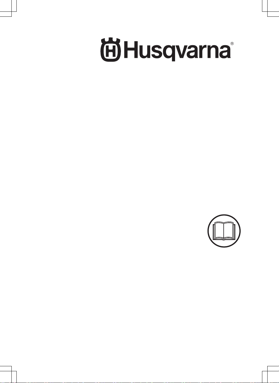
1.4 Movement pattern
The movement pattern of the product is
random. This means that the lawn is mown
evenly without any mowing lines.
1.5 Working method
Automower® 315X/430X/450X use GPSassisted navigation to start mowing in a place
in the yard where it has not been lately. For
the other models you might have to set remote
start settings to make sure that the lawn is cut
evenly, refer to the complete Operator’s
Manual on Husqvarna’s website.
When the product hits an obstacle or
approaches the boundary wire the product
reverses and selects a new direction. Sensors
at the front and back will sense when the
product is approaching the boundary wire. The
front always passes the boundary wire by a
specific distance before the product turns
around. The distance can be changed to
adapt to the installation if required.
The STOP button on the top of the product is
mainly used to stop the product when it’s
running. When the STOP button is pushed a
hatch opens, behind which there is a control
panel. The STOP button remains pushed in
until the hatch is closed again. This together
with the START button acts as a start inhibitor.
Note: Always push the START button before
closing the hatch to start the product. If the
START button is not pushed, a message beep
is heard and the product will not start.
Note: When the product is started for the first
time, a start-up sequence begins which
includes a number of important basic settings,
refer to
To do the basic settings
in the
complete Operator’s Manual on Husqvarna’s
website.
1.6 Finding the charging station
The Automower® 305/310/315/315X/
420/430X/440/450X can be set to search for
the charging station in up to 3 different ways.
The product automatically combines these 3
search methods to locate the charging station
as fast as possible, but also to avoid as much
tracks forming as possible. Automower® 105
always follows the guide wire to the charging
station.
1418 - 004 - 10.03.2020
Introduction - 3
Page 4
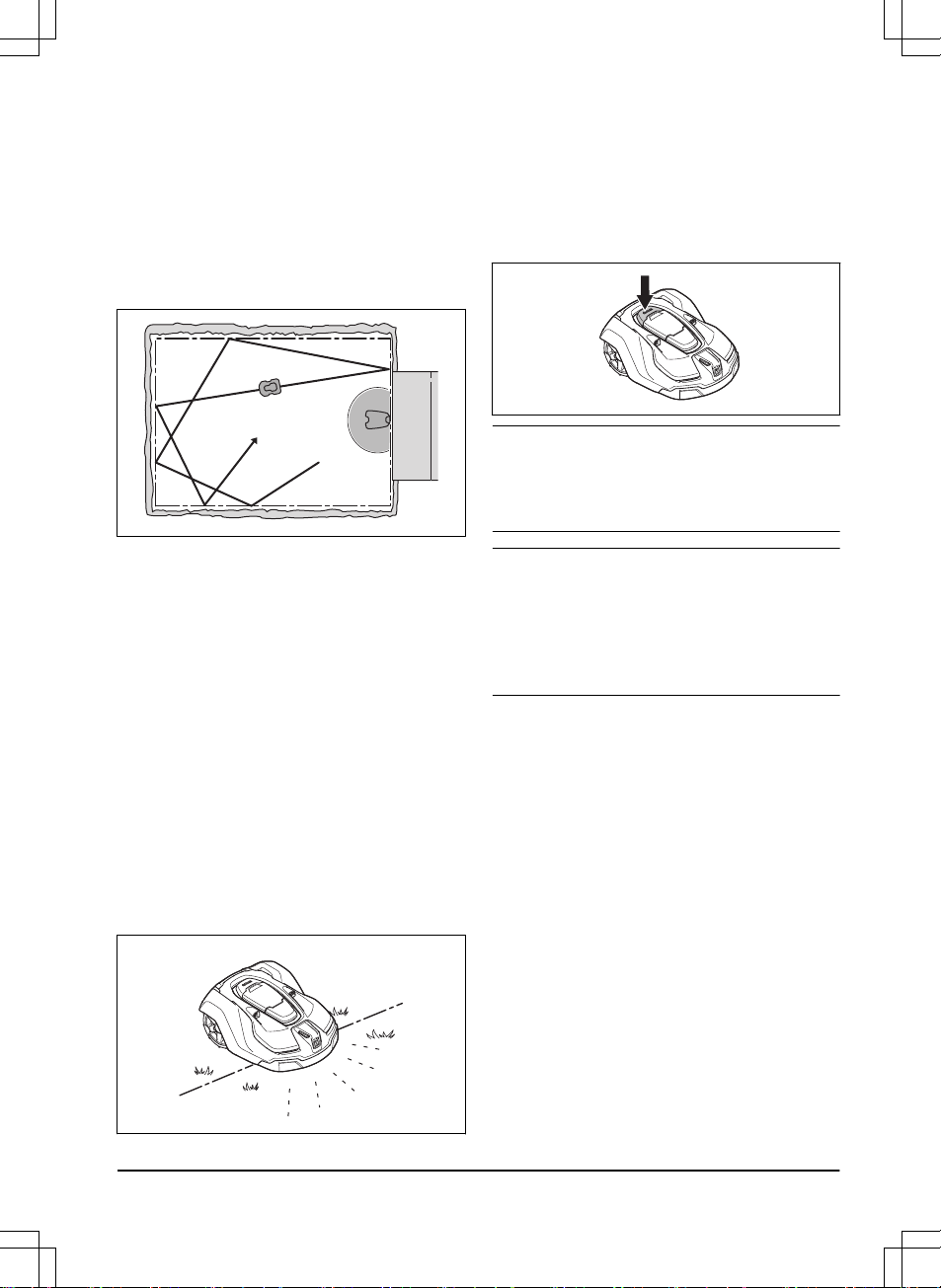
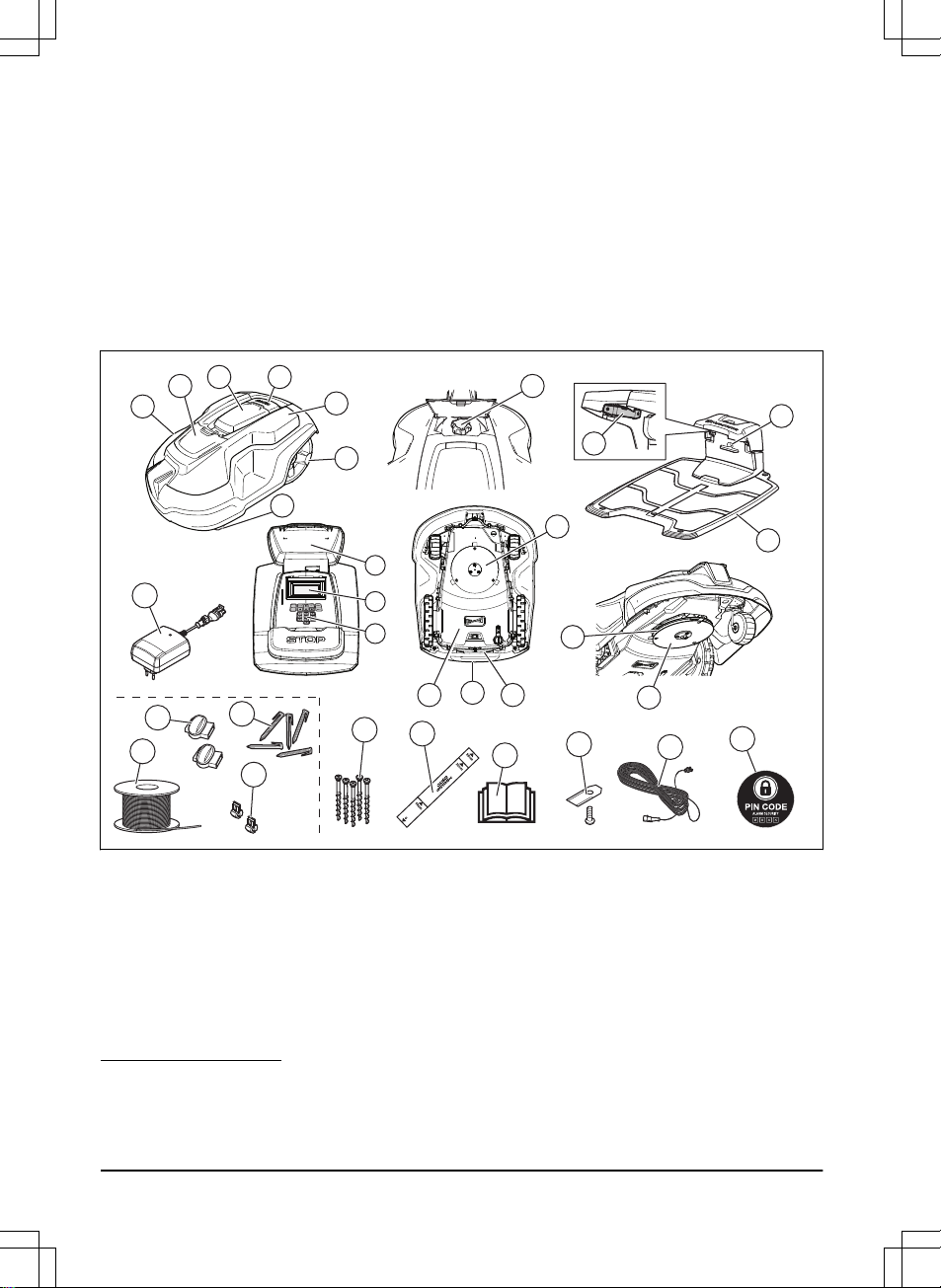
1.7 Product overview Automower® 105
1
32
17
26
6
5
4
13
14
12
21
25
19
24
20
23
18
8
10
11
7
22
15
28
16
9
27
The numbers in the figure represent:
1. Body
2. Hatch to display, keypad and cutting
height adjustment
3. Stop button
4. Contact plates
5. LED for operation check of the charging
station, boundary wire and guide wire
6. Charging station
7. Handle
8. Battery cover
9. Blade disc
10. Skid plate
11. Chassis box with electronics, battery and
motors
12. Main switch
13. Rear wheel
14. Charging plates
15. Keypad
16. Display
17. Loop wire for boundary loop and guide
wire
18. Connectors for the loop wire
19. Stakes
20. Couplers for the loop wire
21. Screws for securing the charging station
4 - Introduction
1418 - 004 - 10.03.2020
Page 5
22. Blades
23. Operator’s Manual and Quick Guide
24. Measurement gauge when installing the
boundary wire (the measurement gauge
is broken loose from the box)
25. Power supply (the appearance may differ
depending on market)
26. Low voltage cable
27. Alarm decal
28. Rating plate (incl. product identification
code)
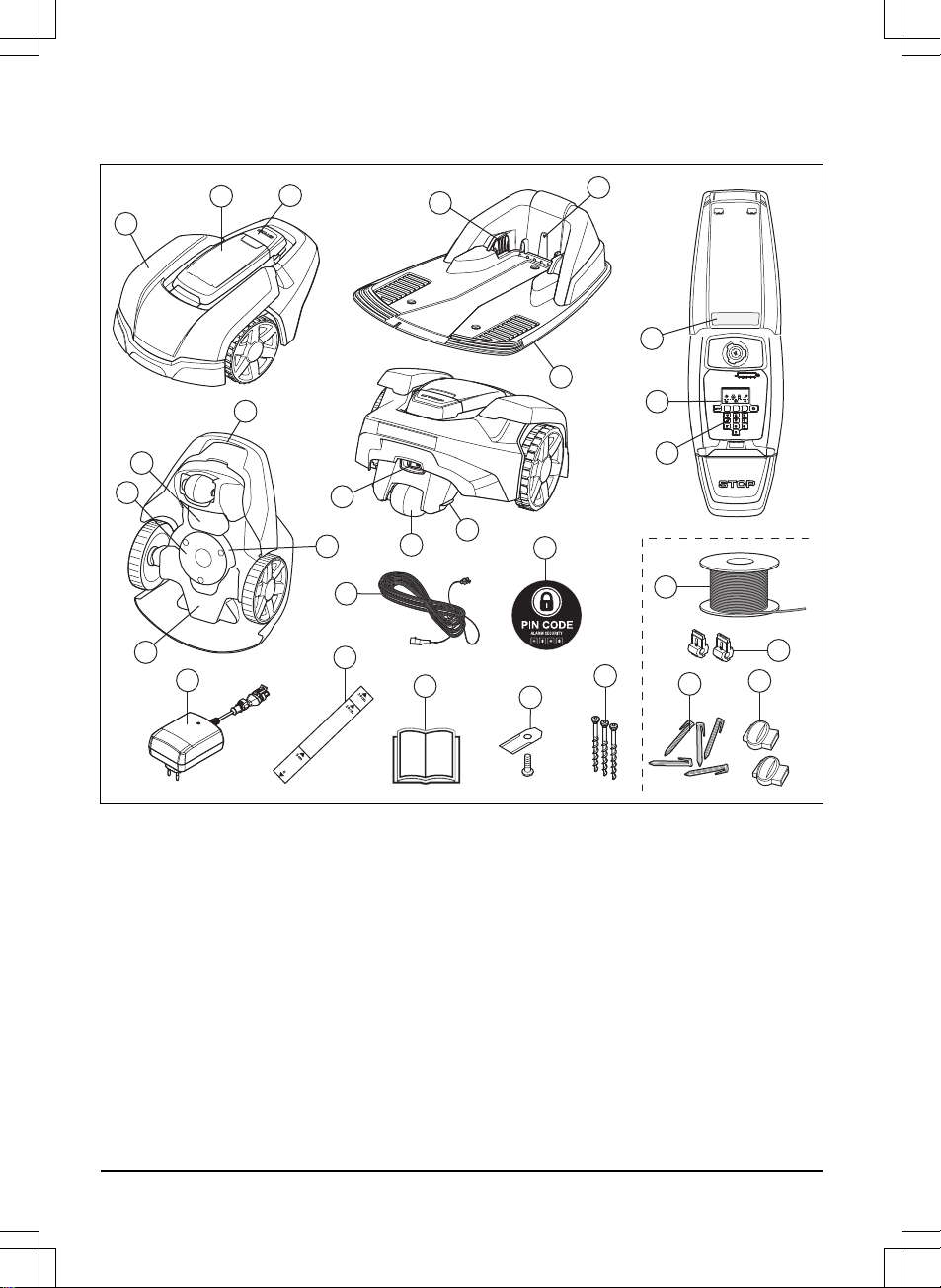
1.8 Product overview Automower® 305
1
2
4
5
6
7
9
15
14
18
16
19
17
13
11
12
24
26
25
27
28
29
30
8
20
23
22
21
3
10
The numbers in the figure represent:
1. Body
2. Hatch to keypad, display and cutting
height adjustment
3. Stop button
4. Rear wheels
5. Front wheels
6. Blade disc
7. Skid plate
8. Contact plates
9. LED for operation check of the charging
station and boundary wire
10. Charging station
11. Display
12. Keypad
13. ON/OFF button
14. Rating plate (incl. product identification
code)
15. Cutting height adjustment
16. Maintenance tool
17. Cutting system
18. Chassis box with electronics, battery and
motors
19. Handle
1418 - 004 - 10.03.2020 Introduction - 5
Page 6
20. Loop wire for boundary loop and guide
wire
1
21. Couplers for the loop wire
2
22. Stakes
3
23. Connectors for the loop wire
4
24. Screws for securing the charging station
25. Power supply (the appearance may differ
depending on market)
26. Measurement gauge when installing the
boundary wire (the measurement gauge
is broken loose from the box)
27. Operator’s Manual and Quick Guide
28. Extra blades
29. Low voltage cable
30. Alarm decal
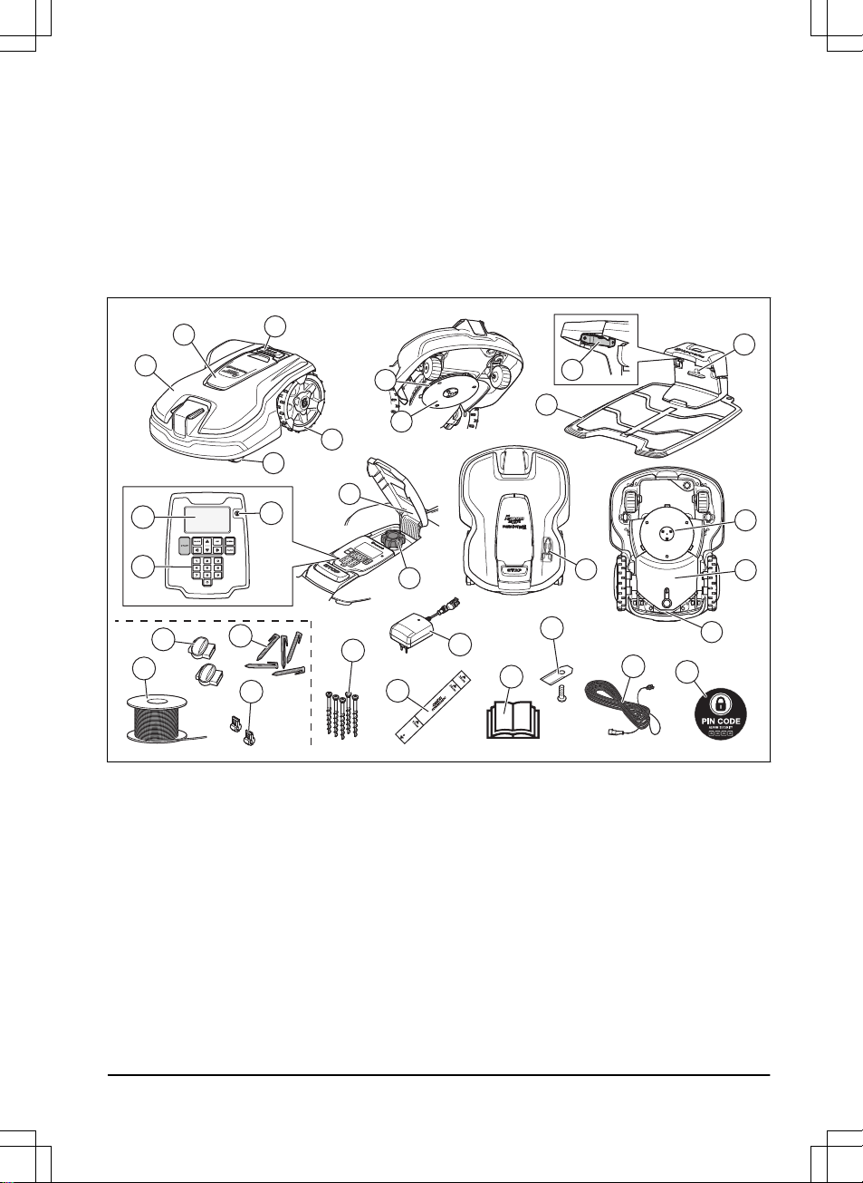
1.9 Product overview Automower® 310/315/315X
1
12
13
14
2
3
4
5
6
9
8
11
15
10
1816
17
22
20
19
21
25
26
27
23
28
29
30
31
7
24
The numbers in the figure represent:
1. Body
2. Hatch to cutting height adjustment
3. Hatch to display and keypad
4. Stop button
5. Replaceable cover
6. Rear wheels
7. Front wheels
8. Cutting height adjustment
9. Contact plates
10. LED for operation check of the charging
station and boundary wire
11. Charging station
1
Is a part of the Installation kit which is purchased separately.
2
Is a part of the Installation kit which is purchased separately.
3
Is a part of the Installation kit which is purchased separately.
4
Is a part of the Installation kit which is purchased separately.
6 - Introduction 1418 - 004 - 10.03.2020
Page 7

12. Rating plate (incl. product identification
code)
13. Display
14. Keypad
15. Cutting system
16. Chassis box with electronics, battery and
motors
17. Handle
18. Main switch
19. Blade disc
20. Skid plate
21. Power supply (the appearance may differ
depending on market)
22. Loop wire for boundary loop and guide
wire
5
23. Couplers for the loop wire
6
24. Stakes
7
25. Connectors for the loop wire
8
26. Screws for securing the charging station
27. Measurement gauge when installing the
boundary wire (the measurement gauge
is broken loose from the box)
28. Operator’s Manual and Quick Guide
29. Extra blades
30. Low voltage cable
31. Alarm decal
5
Is a part of the Installation kit which is purchased separately.
6
Is a part of the Installation kit which is purchased separately.
7
Is a part of the Installation kit which is purchased separately.
8
Is a part of the Installation kit which is purchased separately.
1418 - 004 - 10.03.2020 Introduction - 7
Page 8
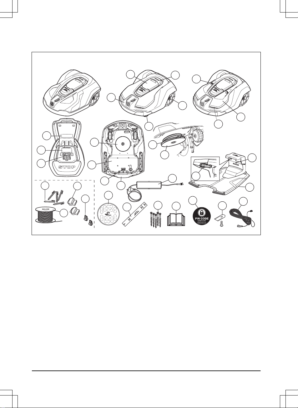
1.10 Product overview Automower® 420/430X/440/450X
Automower 420/440 Automower 430X Automower 450X
23
22
28
24
25
27
26
21
31
32
30
29
4
5
2
3
1
19
20
9
11
10
12
13
14
15
16
17
6
7
8
18
The numbers in the figure represent:
1. Body
2. Hatch to display and keypad
3. Stop button
4. Front wheels
5. Rear wheels
6. Ultrasonic sensors
7. Headlights
8. Replaceable cover
9. Rating plate (incl. product identification
code)
10. Display
11. Keypad
12. Cutting system
13. Chassis box with electronics, battery and
motors
14. Main switch
15. Handle
16. Blade disc
17. Skid plate
18. Contact plates
19. LED for operation check of the charging
station and boundary wire
20. Charging station
21. Power supply (the appearance may differ
depending on market)
22. Cable markers
23. Measurement gauge when installing the
boundary wire (the measurement gauge
is broken loose from the box)
24. Screws for securing the charging station
25. Operator’s Manual and Quick Guide
8 - Introduction
1418 - 004 - 10.03.2020
Page 9
26. Alarm decal
27. Extra blades
28. Low voltage cable
29. Couplers for the loop wire
9
30. Loop wire for boundary loop and guide
wire
10
31. Stakes
11
32. Connectors for the loop wire
12
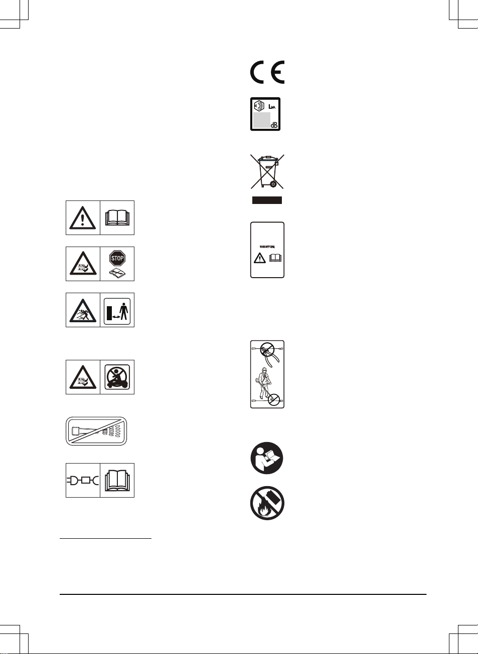
1.11 Symbols on the product
These symbols can be found on the product.
Study them carefully.
WARNING: Read the
user instructions before
operating the product.
WARNING: Disable the
product before working
on or lifting the machine.
WARNING: Keep a safe
distance from the machine when operating.
Keep your hands and
feet away from the rotating blades.
WARNING: Do not ride
on the machine. Never
put your hands or feet
close to or under the
machine.
Never use a high-pressure washer or even
running water to clean
the product.
Use a detachable power
supply as defined on the
rating label next to the
symbol.
This product conforms to the
applicable EC Directives.
Noise emission to surroundings.
The product’s emissions are set
out in
Technical data on page 25
and on the rating plate.
It is not permitted to dispose this
product as normal household
waste. Ensure that the product is
recycled in accordance with local
legal requirements.
The chassis contains components
which are sensitive to electrostatic
discharge (ESD). The chassis
must also be resealed in a
professional manner. For these
reasons the chassis shall only be
opened by authorized service
technicians. A broken seal can
result in the entire or parts of the
guarantee no longer being valid.
The low voltage cable must not be
shortened, extended or spliced.
Do not use a trimmer nearby the
low voltage cable. Be careful when
trimming edges where the cables
are placed.
1.12 Symbols on the battery
Read the user instructions.
Do not discard the battery into fire
and do not expose the battery to a
heat source.
9
Is a part of the Installation kit which is purchased separately.
10
Is a part of the Installation kit which is purchased separately.
11
Is a part of the Installation kit which is purchased separately.
12
Is a part of the Installation kit which is purchased separately.
1418 - 004 - 10.03.2020 Introduction - 9
Page 10
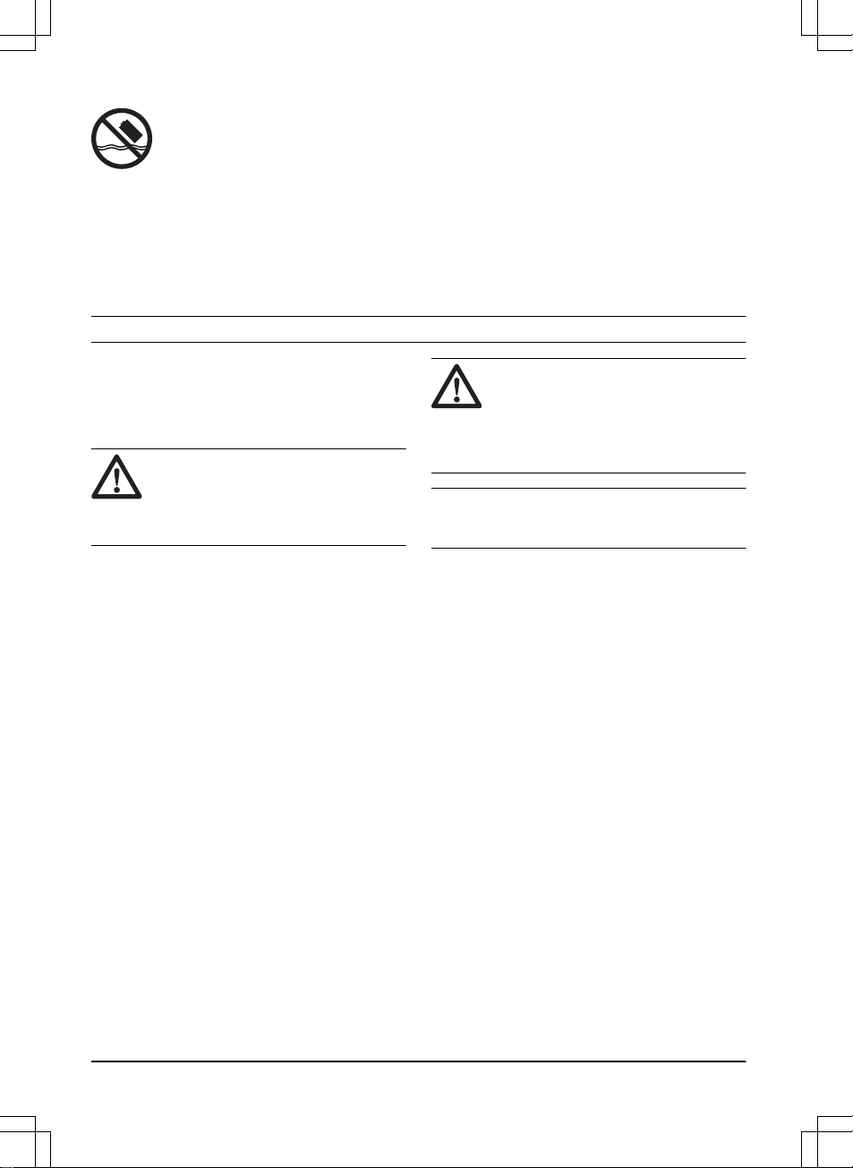
Do not immerse the battery into
water.
1.13 General manual instructions
The following system is used in the Operator’s
Manual to make it easier to use:
• Text written in
italics
is a text that is
shown on the display of the product or is
a reference to another section in the
Operator’s Manual.
• Text written in bold is one of the buttons
on the keypad of the product.
• Text written in
UPPERCASE
and
italics
refer to the different operating modes
available in the product.
2 Safety
2.1 Safety definitions
Warnings, cautions and notes are used to
point out specially important parts of the
manual.
WARNING: Used if there is a risk
of injury or death for the operator or
bystanders if the instructions in the
manual are not obeyed.
CAUTION: Used if there is a risk
of damage to the product, other
materials or the adjacent area if the
instructions in the manual are not
obeyed.
Note: Used to give more information that is
necessary in a given situation.
2.1.1 IMPORTANT. READ CAREFULLY
BEFORE USE. KEEP FOR FUTURE
REFERENCE
The operator is responsible for accidents or hazards occurring to
other people or property.
This appliance is not intended for use by persons (including
children) with reduced physical, sensory or mental capabilities (that
could affect a safe handling of the product), or lack of experience
and knowledge, unless they have been given supervision or
instruction concerning use of the appliance by a person
responsible for their safety.
This appliance can be used by children aged from 8 years and
above and persons with reduced physical, sensory or mental
capabilities or lack of experience and knowledge if they have been
given supervision or instruction concerning use of the appliance in
a safe way and understand the hazards involved. Local regulations
10 - Safety
1418 - 004 - 10.03.2020
Page 11
may restrict the age of the operator. Cleaning and maintenance
shall not be made by children without supervision.
Never connect the power supply to an outlet if the plug or cord is
damaged. Worn or damaged cord increase the risk of electric
shock.
Only charge the battery in the included charging station. Incorrect
use may result in electric shock, overheating or leaking of
corrosive liquid from the battery. In the event of leakage of
electrolyte, flush with water/neutralizing agent. Seek medical help if
it comes in contact with the eyes.
Use only original batteries recommended by the manufacturer.
Product safety cannot be guaranteed with other than original
batteries. Do not use non-rechargeable batteries.
The appliance must be disconnected from the supply mains when
removing the battery.
WARNING: The product
can be dangerous if used
incorrectly.
WARNING: Do not use
the product when
persons, especially
children, or animals, are
in the work area.
WARNING: Keep your
hands and feet away
from the rotating blades.
Never put your hands or
feet close to or under the
product when the motor
is running.
WARNING: In the event
of an injury or accident
seek medical help.
2.2 Use
• The product may only be used with the
equipment recommended by the
manufacturer. All other types of use are
incorrect. The manufacturer’s instructions
with regard to operation/maintenance and
repair must be followed precisely.
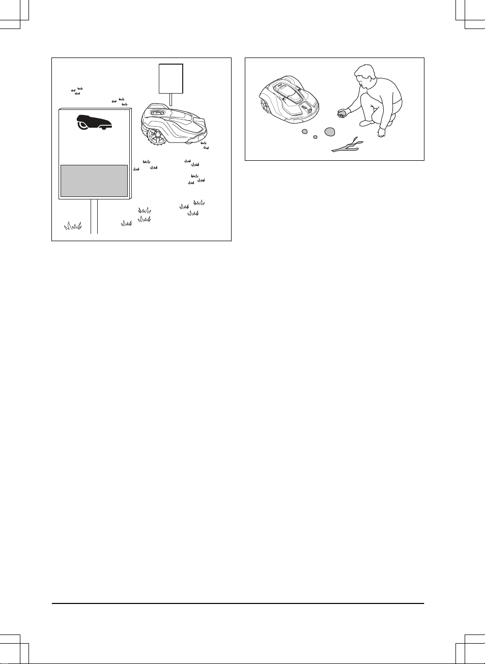
• Warning signs shall be placed around the
work area if the product is used in public
areas. The signs shall have the following
text: Warning! Automatic lawn mower!
Keep away from the machine! Supervise
children!
1418 - 004 - 10.03.2020
Safety - 11
Page 12
WARNING!
Automatic lawnmower!
Keep away from the machine!
Supervise children!
I am a robotic lawnmower and I work here quietly
to keep the lawn in perfect condition.
I work 24/7 independently of weather conditions and do it
without releasing any exhaust emissions.
Stay a while and enjoy my work,
but please let me work in peace.
• Use the PARK function or switch off the
product when persons, especially
children, or animals are in the work area.
It is recommended to program the product
for use during hours when the area is free
from activity, e.g. at night. Consider that
certain species, e.g. hedgehogs, are
active at night. They can potentially be
harmed by the product.
• The product may only be operated,
maintained and repaired by persons that
are fully conversant with its special
characteristics and safety regulations.
Please read the Operator’s Manual
carefully and make sure you understand
the instructions before using the product.
• It is not permitted to modify the original
design of the product. All modifications
are made at your own risk.
• Check that there are no foreign objects
such as stones, branches, tools or toys
on the lawn. If the blades hit foreign
objects the blades can be damaged.
Always switch off the product with the
main switch or ON/OFF button before
clearing a blockage. Inspect the product
for damage before staring the product
again.
• If the product starts to vibrate abnormally.
Always switch off the product with the
main switch or ON/OFF button and
inspect for damage before staring the
product again.
• Start the product according to the
instructions. When the product is enabled
with the ON/OFF button or when the main
switch is set to
1
make sure to keep your
hands and feet away from the rotating
blades. Never put your hands and feet
under the product.
• Never touch moving hazardous parts,
such as the blade disc, before it has
come to a complete stop.
• Never lift up the product or carry it around
when it is switched on.
• The product must never be allowed to
collide with persons or other living
creatures. If a person or other living
creature comes in the product’s way it
shall be stopped immediately.
• Do not put anything on top of the product
or its charging station.
• Do not allow the product to be used with a
defective guard, blade disc or body.
Neither should it be used with defective
blades, screws, nuts or cables. Never
connect a damaged cable, or touch a
damaged cable before it is disconnected
from the supply.
• Do not use the product if the main switch
or the ON/OFF button do not work.
• Always switch off the product using the
main switch or the ON/OFF button when
the product is not in use. The product can
only start when the main switch is set to
1
, or the ON/OFF button is switched on
12 - Safety
1418 - 004 - 10.03.2020
Page 13
and the indicator lamp is lit. The correct
PIN code must also be entered for the
product to start.
• The product must never be used at the
same time as a sprinkler. Use the
Schedule
function so the product and
sprinkler never run simultaneously.
• Husqvarna does not guarantee full
compatibility between the product and
other types of wireless systems such as
remote controls, radio transmitters,
hearing loops, underground electric
animal fencing or similar.
• The built-in alarm is very loud. Be careful,
especially if the product is handled
indoors.
• Metal objects in the ground (for example
reinforced concrete or anti-mole nets) can
result in a stoppage. The metal objects
can cause interference with the loop
signal which then can lead to a stoppage.
• Operation and storage temperature is
0-50 °C / 32-122 °F. Temperature range
for charging is 0-45 °C / 32-113 °F. Too
high temperatures might cause damage
to the product.
2.3 Battery safety
WARNING: Lithium-ion batteries
can explode or cause fire if
disassembled, short-circuited,
exposed to water, fire, or high
temperatures. Handle carefully, do
not dismantle, open the battery or
use any type of electrical/
mechanical abuse. Avoid storage in
direct sunlight.
For more information about the battery, refer
to
Battery on page 22
3 Installation
3.1 Connecting the power supply
Take the following into consideration when
planning where to place the power supply:
• Close to the charging station
• Protection from rain
• Protection from direct sunlight
WARNING: The product is only to
be used with a power supply unit
supplied by Husqvarna.
When connecting the power supply, only use
a wall socket that is connected to an earth
fault-breaker (RCD).
WARNING: Risk of Electric Shock.
Install only to an earth-fault breaker
(RCD) when connecting the power
supply to the wall socket. For USA/
CANADA: Use a covered Class A
GFCI receptacle (RCD) that has an
enclosure that is weatherproof with
the attachment plug cap inserted or
removed.
WARNING: No parts of the power
supply must be changed or
tampered with. The low voltage
cable must not be shortened or
extended.
Low-voltage cables of different lengths are
available as accessories.
WARNING: The power supply
cable and extension cable must be
outside the work area to avoid
damage to the cables.
1418 - 004 - 10.03.2020 Installation - 13
Page 14
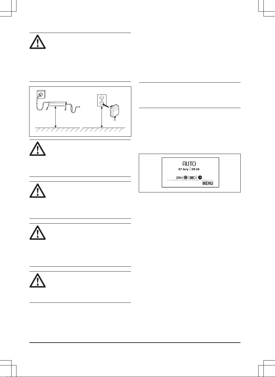
WARNING: Do not under any
circumstances mount the power
supply at a height where there is a
risk it can be submerged in water (at
minimum 30 cm / 12" from the
ground). It is not permitted to place
the power supply on the ground.
min 30 cm / 12”
WARNING: Use the plug to
disconnect the charging station, for
instance before cleaning the
charging station or repairing the loop
wire.
WARNING: Place the low voltage
cable and adjust the cutting height
so that the blades on the blade disc
can never come in contact with the
cable.
WARNING: To reduce the risk of
damage to electrical components,
disconnect all connections to the
charging station (power supply,
boundary wire and guide wires) if
there is a risk of a thunderstorm.
WARNING: Do not encapsulate
the power supply. Condensed water
can harm the power supply and
increase the risk of electrical shock.
For more instructions on how to do a proper
installation, refer to chapter
Installation
in the
complete Operator's manual on Husqvarna's
website www.husqvarna.com.
3.2 Control panel
All commands and settings for the product are
made via the control panel. All functions are
accessed via a number of menus.
The control panel consists of a display and a
keypad. All information is shown on the
display and all input is done using the buttons.
Note: The display texts are shown in English
in the manual, but you will see the texts on the
product display in the chosen language.
3.3 Display Automower® 105
When the STOP button has been pushed and
the hatch is opened, the operation window
appears showing the time, selected operating
mode, number of mowing hours, battery status
and timer setting.
• The clock shows the current time.
• Date shows the current day.
• The number of operating hours indicates
the number of hours since the day of
manufacture that the product has been in
operation. The time that the product has
spent mowing or searching for the
charging station is counted as operating
time.
•
AUTO, MAN
or
HOME
show which mode
of operation is selected.
• The battery status shows the remaining
battery charge.
• The ECO symbol is displayed if the
product is set in
ECO mode
.
• The clock symbol indicates when the
timer settings are set. The clock symbol is
black when the product is not allowed to
mow due to a timer setting.
• The
MENU
text illustrates that the main
menu can be reached by pushing the
14 - Installation
1418 - 004 - 10.03.2020
Page 15
multi-choice button that is located under
the text.
3.4 Keypad Automower® 105
The keypad consists of 4 groups of buttons:
• The START button is used to activate the
product. This is normally the last button to
be pushed before closing the hatch.
• The 3 multi-choice buttons offer various
functions, depending on where in the
menu structure you are.
• The number buttons are used for instance
to enter the PIN code or time settings.
• The operation selection button is
symbolized by a house. When the button
has been pushed, the selected operation
mode is shown in the display.
3.5 Display Automower
®
305/310/315/315X/420/430X/440/450X
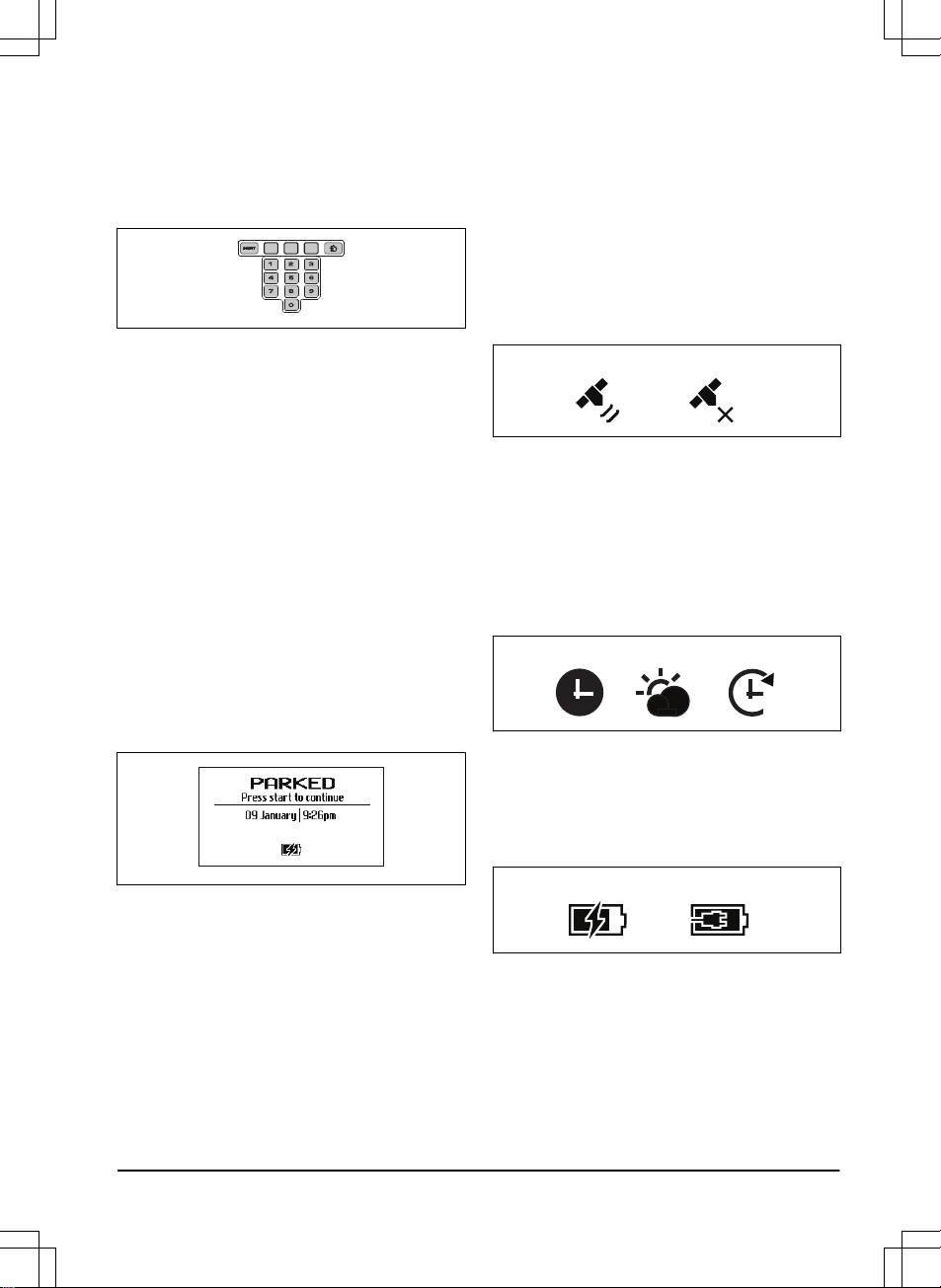
When the STOP button has been pushed and
the hatch is opened, the following information
is displayed:
• Operating information, e.g.
READY
,
MOWING, PARKED
or
SCHEDULE
.
READY
is displayed if the product is not
in any specific operating mode, e.g. if the
product has just been switched on. If the
STOP button is pushed the product
displays what it did prior to the stop, e.g.
MOWING
or
SEARCHING
.
• Date and clock show the current time.
• For Automower
®
315X/430X/450X: The
satellite symbol is shown when the GPSsupported navigation is activated. Symbol
(A) is shown when the symbol has made
contact with a sufficient number of GPS
satellites. Symbol (B) shows when the
product has not made contact with a
sufficient number of GPS satellites.
Symbol (A) blinks during the first days the
product is working, as it is collecting GPS
information about the installation.
A B
• The ECO symbol is displayed if the
product is set in
ECO mode
.
• The black clock symbol (A) is shown
when the product is not allowed to mow
due to a
Schedule
setting. If the product
is not allowed to mow due to
Weather
timer
, symbol (B) is shown. If the
operation mode
Override schedule
is
chosen, symbol (C) is shown.
A B C
• The battery status shows the remaining
battery charge. If the product is loading, a
flash is also shown over the battery
symbol (A). If the product is placed in the
charging station without charging, (B) is
shown.
A B
• The height adjustment setting is displayed
as a scale/numerical value.
• For Automower® Connect@Home (refer
to
Automower® Connect@Home on page
19
): An icon for Bluetooth® wireless
communication will appear in the product
display when connection with your mobile
device has been established.
1418 - 004 - 10.03.2020
Installation - 15
Page 16
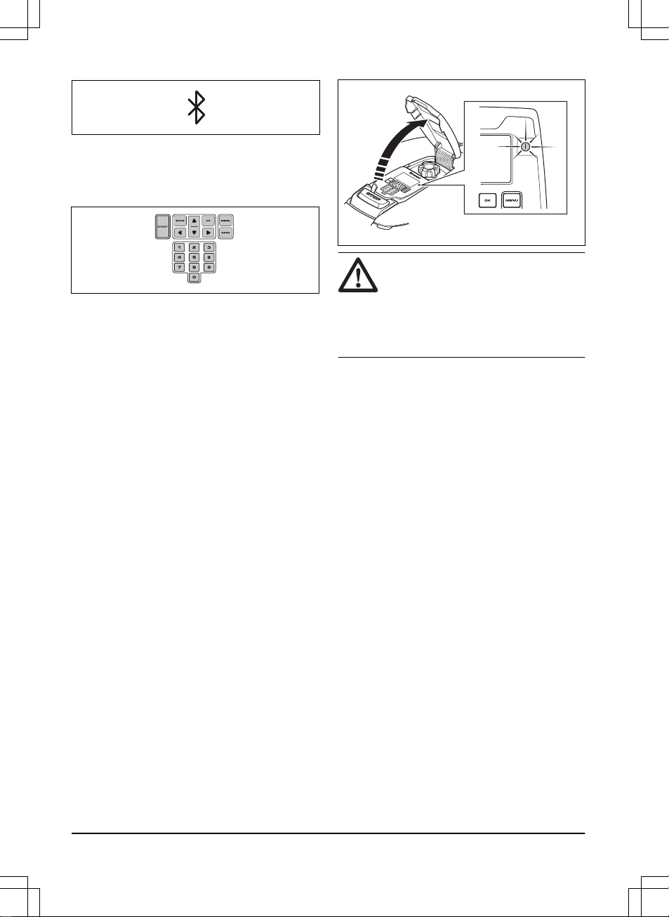
3.6 Keypad Automower
®
305/310/315/315X/420/430X/440/450X
The keypad consists of 6 groups of buttons:
• The START button is used to activate the
product. This is normally the last button to
be pushed before closing the hatch.
• The BACK and OK buttons are used to
navigate in the menu. The OK button is
also used to confirm settings.
• The arrow button are used to navigate in
the menu but also to make selections in
certain setting options.
• The MENU button is used to go to the
main menu.
• The PARK button is used to send the
product to the charging station.
• The number buttons are used to enter
settings, for example PIN code, time or
exit direction.
3.7 The indicator lamp Automower
®
305
The indicator lamp on the ON/OFF button is
an important status indicator:
• The product is active if the indicator lamp
lights continuously.
• The product is in standby if the indicator
lamp flashes. This means that the
operator must push the ON/OFF button to
make the product active again.
• The product is disabled when the
indicator lamp is not lit.
WARNING: It is only safe to carry
out inspection or maintenance on
the product when the product is
disabled. The product is disabled
when the lamp on the ON/OFF
button is not lit.
3.8 Menu structure
The main menu for Automower® 105 offers 4
options. Automower® 310 has 6 options and
Automower® 305/315/315X has 7 options.
The main menu for Automower® 420/430X/
440/450X offers 8 options.
3.9 Submenus
There are a number of submenus under each
option. You can access all the functions to set
the product settings via the submenus.
Certain submenus contain options that are
ticked off to the left. This means that these
options are selected. Check or uncheck the
box by pushing the OK button.
3.10 Browse between menus
Browse through the main menu and
submenus with the help of the multi-choice
buttons (Automower® 105) or the arrow
buttons (Automower® 305/310/315/315X/
420/430X/440/450X). Enter values and times
using the number buttons and confirm each
selection with the multi-choice button marked
OK. Push BACK to go up a step in the menu
or keep the HOME (Automower® 105)
alternatively MENU (Automower
®
305/310/315/315X/420/430X/440/450X)
16 - Installation
1418 - 004 - 10.03.2020
Page 17
button pushed in for 2 seconds to go directly
to the main menu.
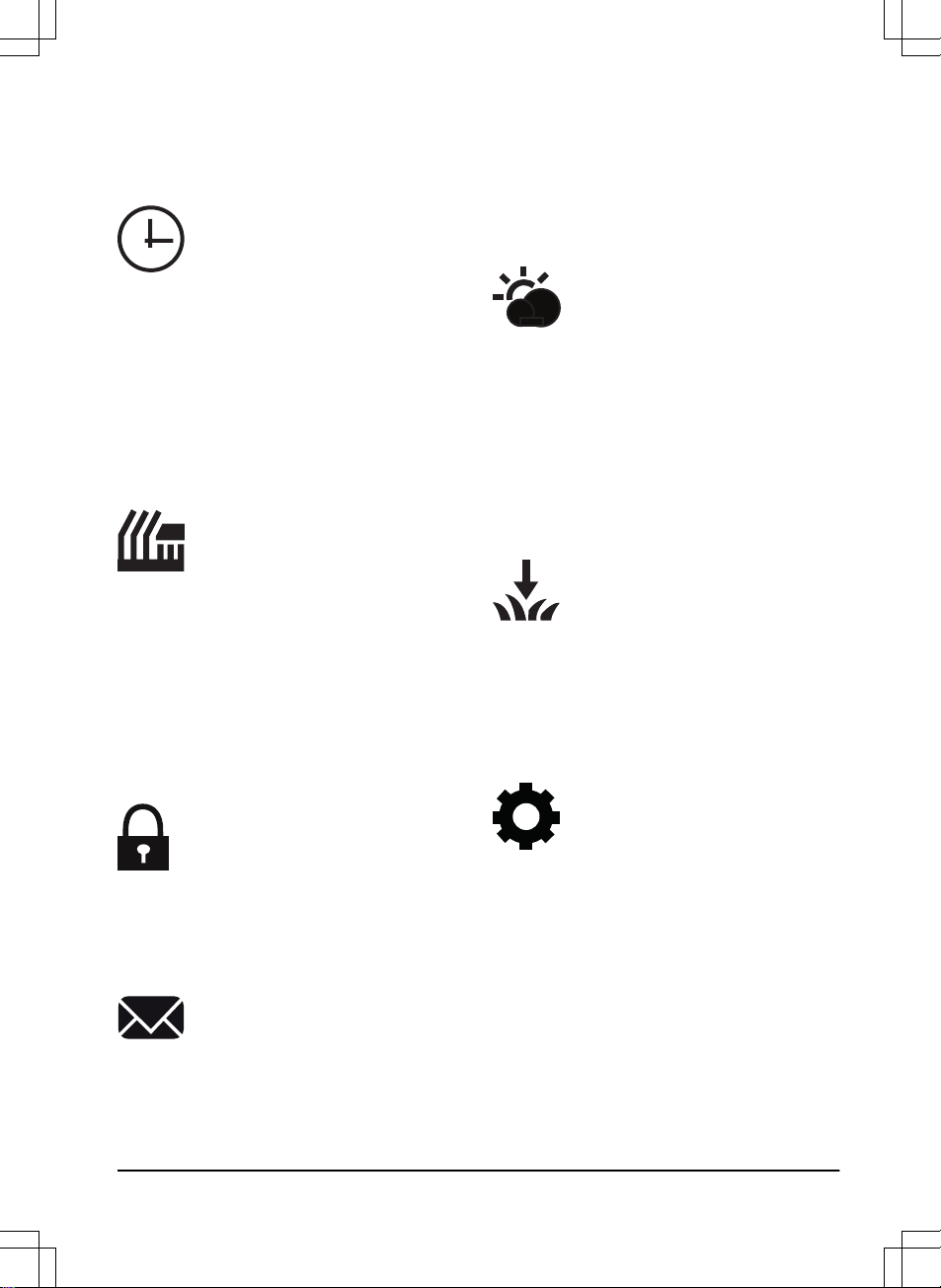
3.11 Main menu
Schedule
The lawn should not be cut too
often to obtain the best mowing
result. Consequently, it is
important to limit the operating
time using the
Schedule
function if
the work area is less than the
product’s work capacity. The
Schedule
function is also an ideal
tool to control which periods the
product should not mow, for
example when children are playing
on the lawn.
Cutting height
Applicable for Automower
®
420/430X/440/450X
The cutting height can be varied
from MIN (1) to MAX (9). During
the first week after a new
installation, the cutting height must
be set to MAX to avoid damaging
the loop wire. After this, the cutting
height can be lowered one step
every week until the desired
cutting height has been reached.
Security
In this menu, settings relating to
security and the connection
between the product and the
charging station can be made.
There are 3 security levels to
choose from:
Low, Medium, High
.
Messages
Applicable for Automower
®
305/310/315/315X/420/430X/
440/450X
Historical fault and information
messages can be read in this
menu. For some of the most
common fault messages, there are
tips and advice to help you rectify
the fault.
Weather timer
Applicable for Automower
®
305/315/315X/420/430X/440/450X
This function allows the product to
automatically adjust its mowing
times based on how much the
lawn grows. When the weather is
good for grass growth, the product
mows more often and when grass
growth is low the product
automatically spends less time on
the lawn.
Installation
This menu function is used to
customize the installation. For
many work areas there is no need
to alter the factory settings, but
depending on the lawn complexity
the mowing result can be
improved by making manual
settings.
Settings
This selection allows you to make
changes to the general product
settings such as date and time.
You can also switch on/off
ECO
mode
and
Spiral cutting
, or save
your settings in different
Profiles
(Automower® 305/315/315X/
420/430X/440/450X only).
Husqvarna recommends to let
ECO mode
be switched on to save
energy and avoid interference with
other equipment.
1418 - 004 - 10.03.2020 Installation - 17
Page 18
Accessories
Applicable for Automower
®
305/310/315/315X/420/430X/
440/450X
This menu handles the settings for
the product accessories, for
examples Automower® Connect or
Automower® Connect@Home.
Contact your local Husqvarna
representative for information on
what accessories are available for
your product.
4 Operation
4.1 To switch on, stop and switch off
the product
• The product can only start if it is switched
on and the correct PIN code has been
entered. To switch on the Automower
®
305, push the ON/OFF button for 3
seconds and check that the indicator
lamp is lit. To switch on all other models,
set the main switch to
1
.
• To stop to product, push the STOP button
on top of the product. The product stops
and the blade motor stops.
• To switch off Automower® 305, push the
ON/OFF button for 3 seconds and check
that the indicator lamp is not lit. To switch
off all other models, the main switch is set
to 0.
4.2 Operating mode Automower® 105
Push the Operation selection button 1-3 times
to select an operating mode. You can select
between 3 different operating modes.
•
HOME
. Sends the product to the charging
station. It remains here until another
operation mode is selected. When the
battery is fully charged, the product will
not leave the charging station and begin
mowing until the operation selection is
altered to
AUTO
.
•
AUTO
. The standard, automatic operation
mode where the product mows and
charges automatically.
•
MAN
. When mowing secondary areas the
MAN
setting must be used. If
MAN
is
selected and the product is started when
it is out on the lawn, it mows until the
battery runs out. It then stops and
the ’Needs manual charging’ message
appears. The product must then be
moved manually to the charging station
and then started manually after charging.
If the product charges in the
MAN
mode,
it will fully charge, move about 20 cm / 8
in. out of the charging station and then
stop. This indicates that it is charged and
ready to start mowing.
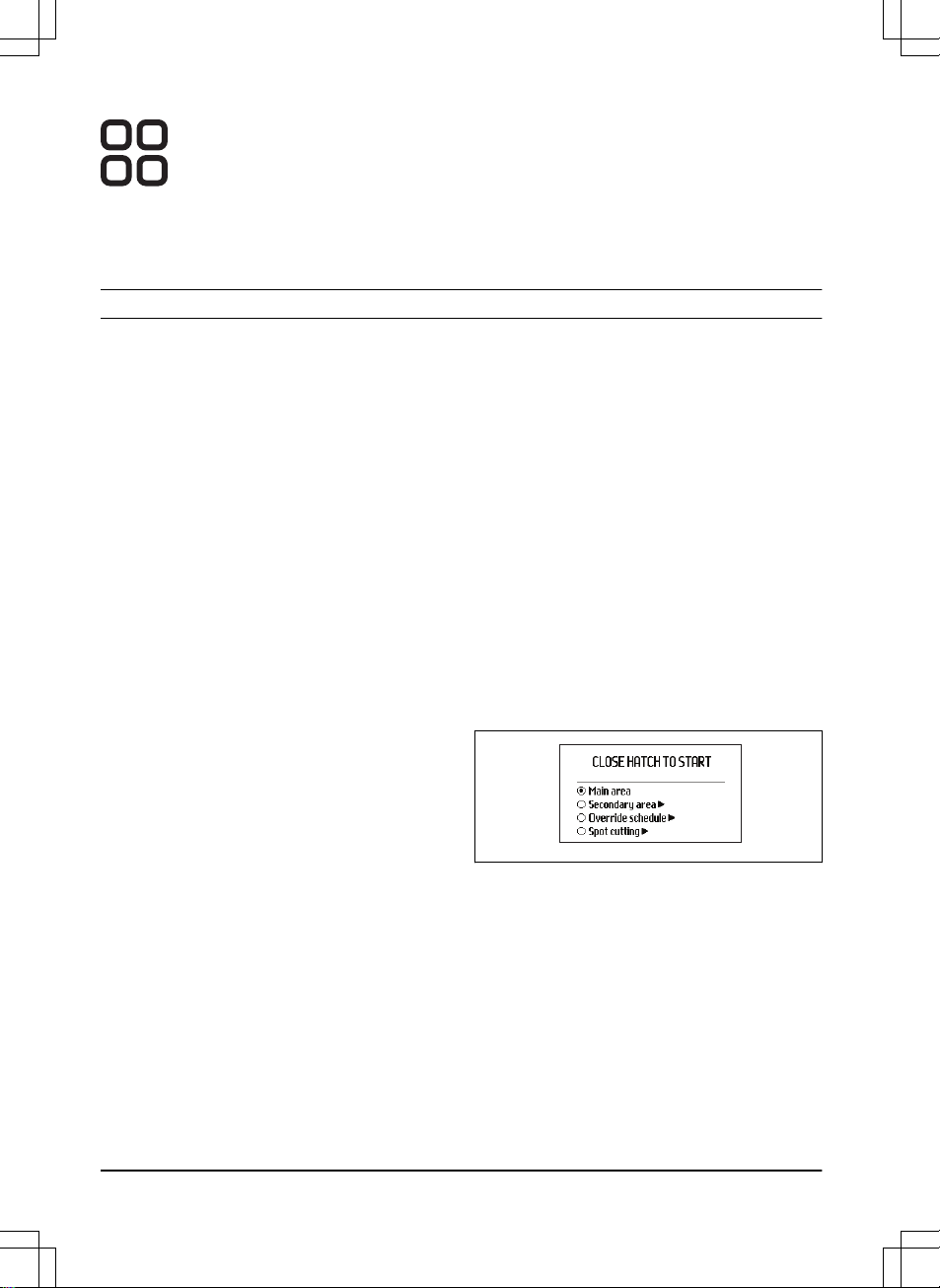
4.3 Operating mode, START
Automower® 305/310/315/315X/
420/430X/440/450X
Push the START button to select one of the
following operating modes:
•
Main area:
The standard operating mode
where the product mows and charges
automatically.
•
Secondary area:
When mowing
secondary areas this setting must be
chosen.
In the
Secondary area
mode, the operator
must move the product manually between the
main area and the secondary area. The
product mows until the battery is empty. When
the battery is charged, the product moves out
of the charging station and stops. The product
is now prepared to start operation, but needs
confirmation from the operator first.
18 - Operation
1418 - 004 - 10.03.2020
Page 19
Note: If you want to cut the main area after
the battery is charged, set the product to
Main
area
mode before placing it in the charging
station.
•
Override Schedule:
Any
Schedule
settings made can be temporarily
overridden by selecting
Override
schedule
. It is possible to override the
Schedule
for 24 h or 3 days.
•
Spot Cutting:
(Not available for
Automower® 310). The product works in a
spiral pattern to cut the grass where it has
been mown less than in other parts of the
lawn.
The
Spot Cutting
function is activated with
the START button. You can select how
the product should continue to work once
mowing is finished by pushing the right
arrow button and then specifying
Main
Area
or
Secondary Area
.
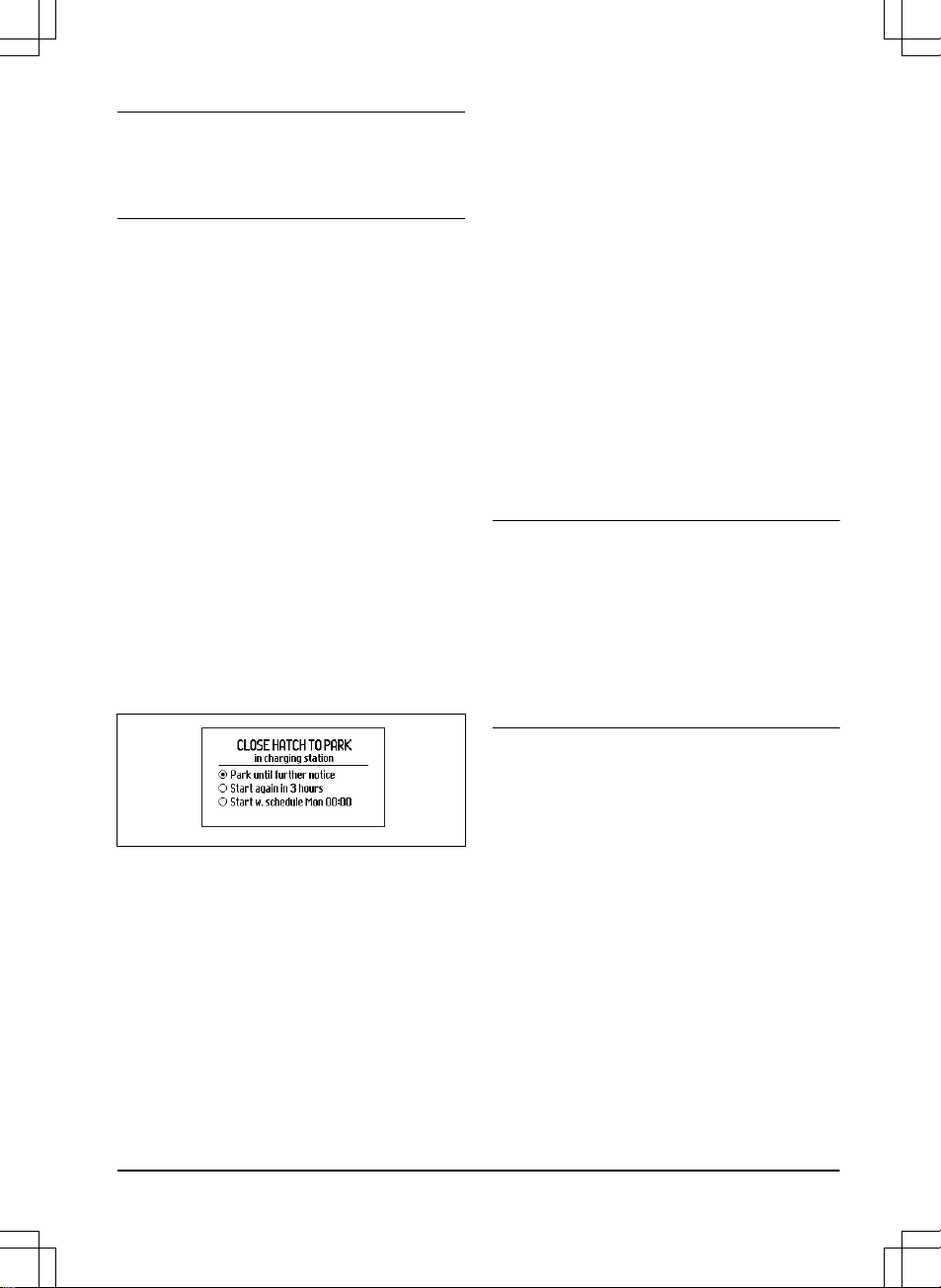
4.4 Operating mode, PARK
Automower® 305/310/315/315X/
420/430X/440/450X
Push the PARK button to select one of the
following operating modes:
•
Park until further notice:
The product
stays in the charging station until another
operating mode is selected by pushing
the START button.
•
Start again in 3 hours:
The product stays
in the charging station for three hours and
then automatically returns to normal
operation. This operation mode is suitable
when there is a need to pause operation,
e.g. for temporary irrigation or for games
on the lawn.
•
Start with schedule:
The product stays in
the charging station until the next
schedule setting permits operation. This
operating mode is suitable if one wishes
to cancel an ongoing mowing cycle and
allow the product to stay in the charging
station until the next day. This option is
not displayed if there are no schedule
settings.
4.5 Connectivity
You can communicate with your product
through the mobile application Automower
®
Connect. Automower® Connect is available for
your mobile device and tablet (Apple or
Android). With Automower® Connect
activated, new icons will be displayed on the
product’s display. For more detailed
information, refer to complete Operator's
manual.
Note: All countries do not support
Automower® Connect because of legal
reasons and regional specified cellular
systems. The included Automower® Connect
lifetime service only applies if there is a third
part sub-supplier of 2G/3G/4G available in the
operational area. In some countries
Bluetooth® is not available due to legal
reasons.
4.5.1 Automower® Connect
Automower® Connect is included in
Automower® 315X/430X/450X and available
as accessory for Automower
®
305/310/315/420/440.
Automower® Connect brings the menu system
to your mobile device, making it easy to read
and change the product settings remotely.
Through this application, you can receive the
product's current status and send commands
to the product from anywhere in the world. In
case of theft, you get an alarm and are be
able to track your product's position.
4.5.2 Automower® Connect@Home
Included in Automower® 305/310/315/315X/
420/430X/440/450X.
1418 - 004 - 10.03.2020
Operation - 19
Page 20
Automower® Connect@Home uses a shortrange Bluetooth® wireless technology. This
means that you can communicate between
the smartphone and the product as long as
you are within communication range. An icon
for Bluetooth communication will appear in the
product display when connection with your
smartphone has been established.
Note: Automower
®
Connect@Home has
similar but not as extensive functionality as
Automower® Connect, and uses the same
app.
4.5.3 Getting started
Download the Automower® Connect app (also
applicable for Automower® Connect@Home)
from AppStore or GooglePlay. Once you have
downloaded the app, you can specify an email address and a password to create an
account. You will receive a validation e-mail to
the e-mail address you specified. Follow the
instructions in the e-mail within 24 hours to
validate your account. If not validated within
24 hours, you will have to create your account
again. When the account has been created in
the app you can pair the product and your
smartphone.
4.5.4 Pair with Automower® Connect
Select the function
Accessories
>
Automower
Connect
>
Pairing
>
New pairing
. When the
app prompts you to do so, enter the 6-digit
code shown on the product display. Also enter
your chosen name of the product into the app.
Automower® Connect is always connected to
your product as long as the mobile device
have contact with the mobile network and the
product is charged and the product is switched
on.
4.5.5 Pair with Automower
®
Connect@Home
Activate Bluetooth® wireless communication
on your smartphone. Select the function
Accessories
>
Connect@Home
>
New pairing
and follow the instructions in the app. After
pairing your product and smartphone they will
automatically connect each time you get into
range. If you want to connect to the product
without having an account you can still use
Automower® Connect@Home by selecting
Automower® Direct in the start-up screen in
the app.
4.6 Adjusting the cutting height
If the grass is long, let the product start
mowing at the MAX cutting height. Once the
grass is shorter, you can gradually lower the
cutting height.
CAUTION: During the first week
after a new installation, the cutting
height must be set to MAX to avoid
damaging the loop wire. After this,
the cutting height can be lowered
one step every week until the
desired cutting height has been
reached.
4.6.1 Automower® 105
The cutting height can be varied from MIN (2
cm / 0.8") to MAX (5 cm / 2.0"). To adjust the
cutting height:
1. Push the STOP button to stop the
product. Then open the hatch.
2. Turn the height adjustment knob to the
required position. The selected position is
indicated by the orange column on the
height adjustment indicator.
1 2 3 4 5
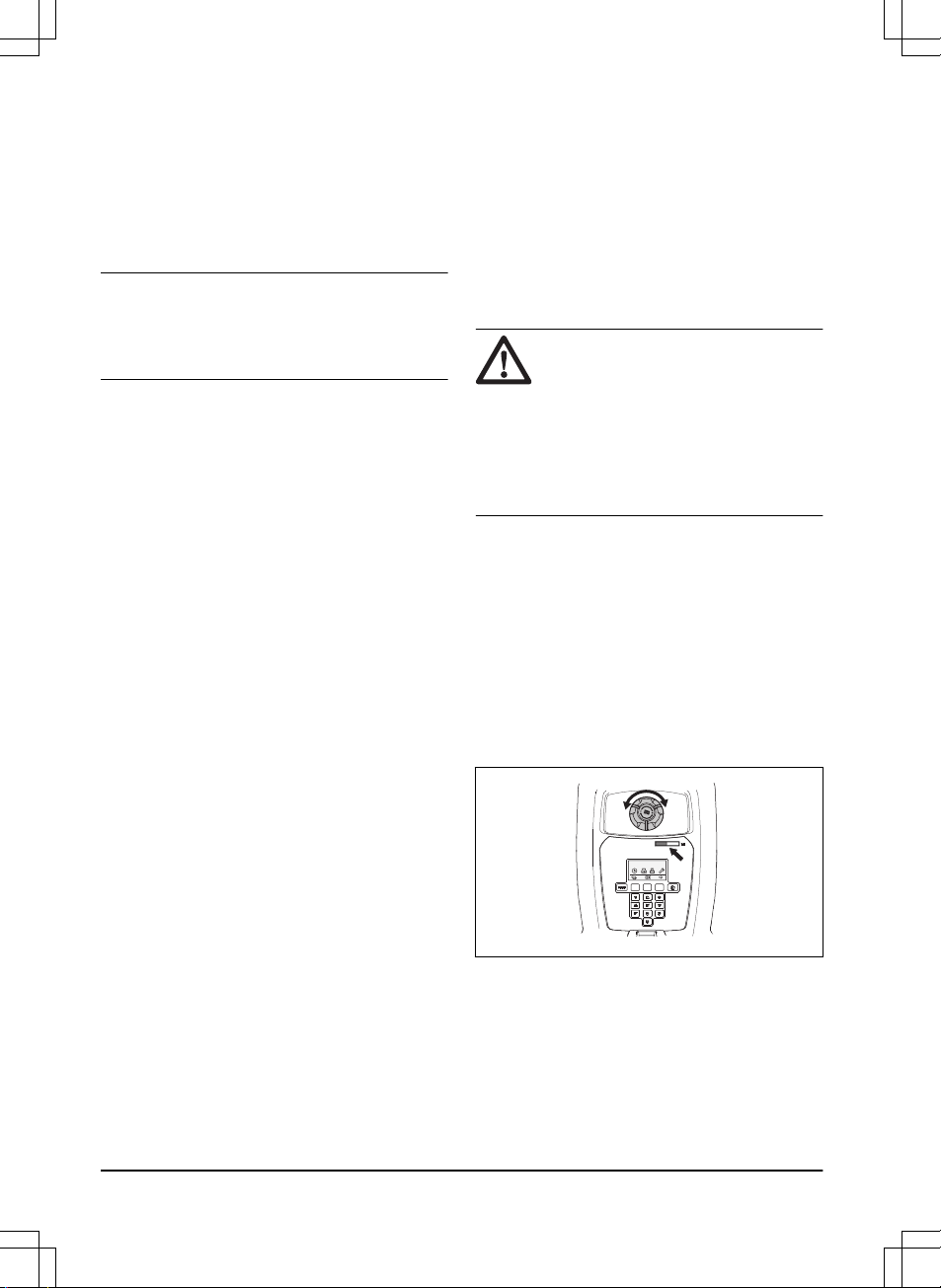
4.6.2 Automower® 305/310/315/315X
The cutting height can be varied from MIN (2
cm / 0.8") to MAX (6 cm / 2.4") in 9 steps.
1. Push the STOP button to stop the product
and open the cutting height adjustment
hatch.
20 - Operation
1418 - 004 - 10.03.2020
Page 21
2. Turn the knob to the required position.
Turn clockwise to increase and counterclockwise to decrease the cutting height.
The arrow aligns with the selected
position marked on the body.
310/315/315X305
4.6.3 Automower® 420/430X/440/450X
The cutting height can be varied from MIN to
MAX in 9 steps.
1. Push the STOP button to stop the product
and open the hatch.
2. Push the MENU button to access the
main menu.
3. Move the cursor using the up/down arrow
buttons to select menu
Cutting height
.
4. Push OK.
5. Increase/Decrease the cutting height with
the arrow buttons.
5 Maintenance
5.1 Cleaning
For better operation and longer service life,
make sure to clean the product regularly and
replace worn parts. The product does not
operate satisfactorily in slopes if the wheels
are blocked with grass. Use a soft brush to
clean the product.
Husqvarna offers a special cleaning and
maintenance kit as an accessory. Contact
your local Husqvarna representative.
WARNING: Wear protective
gloves.
WARNING: Switch off the product
with the main switch or the ON/OFF
button when you turn the product
upside down.
Switch off the product during all
work on the chassis of the product,
such as cleaning or replacing the
blades.
WARNING: Use the plug to
disconnect the charging station
before maintenance, or cleaning of
the charging station or power
supply.
CAUTION: Push the STOP button
and pull the product out of the
charging station before lifting it. Do
not lift the product when it is parked
in the charging station. This can
damage the charging station and/or
the product.
5.1.1 Cleaning Automower
®
105/310/315/315X/420/430X/440/450X
CAUTION: Do not use a high-
pressure washer or running water to
clean the product. Do not use
solvents to clean the product.
5.1.2 Cleaning Automower® 305
Clean the product with a brush or running
water from a water hose.
CAUTION: Do not use a high-
pressure washer to clean the
product. Do not use solvents to
clean the product.
1418 - 004 - 10.03.2020 Maintenance - 21
Page 22
5.2 Battery
WARNING: Only charge the
product using a charging station and
power supply which is intended for
it. Incorrect use may result in electric
shock, overheating or leakage of
corrosive liquid from the battery. In
the event of leakage of electrolyte
flush with water and seek medical
help if it comes in contact with the
eyes etc.
WARNING: Use only original
batteries recommended by the
manufacturer. Product safety cannot
be guaranteed with other batteries.
Do not use non-rechargeable
batteries.
CAUTION: The battery must be
charged fully before winter storage.
If the battery is not fully charged it
can be damaged and in certain
cases be rendered useless.
The charging time can vary depending on,
among other factors, the ambient temperature.
Below indicates that the battery is getting old
and eventually needs replacing:
• The operating time for the product is
shorter than normal between charges.
This leads to more charging cycles than
normal, which increases the risk of tracks
forming near the charging station.
• The product is found standing out on the
lawn with
Empty battery
message. This
indicates that the product does not have
battery capacity enough to find the
charging station.
The battery is fine as long as the product
maintains a well-cut lawn.
Note: Battery life is dependent on the length
of the season and how many hours a day the
product is operating. A long season or many
hours of use a day means that the battery
must be replaced more regularly.
Contact your local Husqvarna representative
to replace the battery.
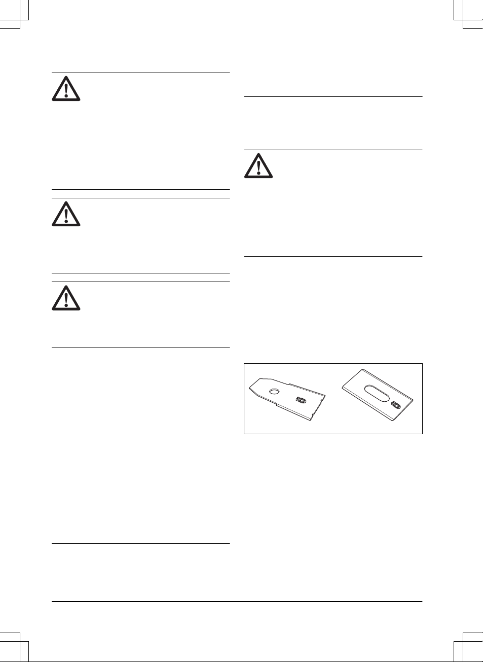
5.3 Replace the blades
WARNING: Use blades and
screws of the right type. Husqvarna
can only guarantee safety when
using original blades. Only replacing
the blades and reusing the screw
can result in a screw wearing during
mowing. The blades can then be
propelled from under the body and
cause serious injury.
Replace worn or damaged parts for safety
reasons. Even if the blades are intact, they
should be replaced on a regular basis for the
best mowing result and low energy usage. All
3 blades and screws must be replaced at the
same time to obtain a balanced cutting
system. Use Husqvarna original blades
embossed with the crowned H-mark logotype,
refer to
Warranty terms on page 34
.
5.4 To replace the blades
1. Switch off the product with the main
switch or the ON/OFF button.
2. Turn the product upside down. Place the
product on a soft and clean surface to
avoid scratching the body and the hatch.
3. Rotate the skid plate so that its holes
align with the screws for the blade.
4. Remove the 3 screws. Use a straight slot
or cross-tip screwdriver.
5. Remove each blade and screw.
22 - Maintenance
1418 - 004 - 10.03.2020
Page 23

6. Fasten new blades and screws. 7. Check that the blades can pivot freely.
6 Troubleshooting
6.1 Troubleshooting
In case of malfunction, a message will appear on the display. For more detailed information on
messages, refer to the complete Operator’s manual on Husqvarna’s website
(www.husqvarna.com. If the same message appears often or if you still cannot find the reason
for the fault, contact your local Husqvarna representative.
Breaks in the loop wire are usually the result of unintentional physical damage to the wire such
as when gardening with a shovel. Breaks can also be due to the wire being stretched excessively
during installation. A wire break can be located by gradually halving the distance of the loop
where the break may have occurred, until there is only a very short section of the wire left. Refer
to the complete Operator’s manual on Husqvarna’s website (
www.husqvarna.com
).
6.1.1 Indicator lamp in the charging station
For a fully functional installation, the indicator lamp in the charging station must emit a solid or
flashing green light. If something else appears, follow the troubleshooting guide below.
There is more help on www.husqvarna.com. If you still need help, please contact your local
Husqvarna representative.
Light Cause Action
Green solid light
Good signals No action required
Green flashing
light
The signals are good and
ECO mode
is activated.
No action required.
Blue flashing light
The boundary loop is not connected
to the charging station.
Check that the boundary wire connectors are fitted properly to the
charging station.
Break in the boundary loop. Find out where the break is. Replace
the damaged section of the loop with
a new loop wire, and splice using an
original coupler.
Red flashing light
Interruption in the charging station’s
antenna.
Contact your local Husqvarna representative.
Red solid light
Fault in the circuit board or incorrect
power supply in the charging station.
The fault should be rectified by an
authorized service technician.
Contact your local Husqvarna representative.
1418 - 004 - 10.03.2020 Troubleshooting - 23
Page 24
7 Transportation, storage and disposal
7.1 Transportation
The supplied Li-ion batteries obey the
Dangerous Goods Legislation requirements.
• Obey all applicable national regulations.
• Obey the special requirement on package
and labels for commercial transportations,
including by third parties and forwarding
agents.
• For how to remove the battery, refer to
the complete Operator's manual on
www.husqvarna.com.
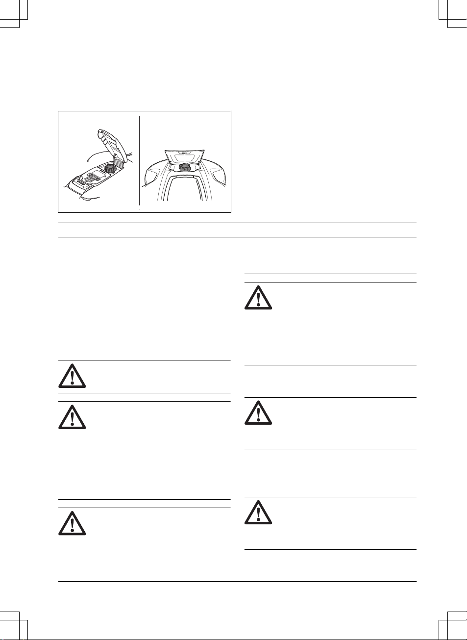
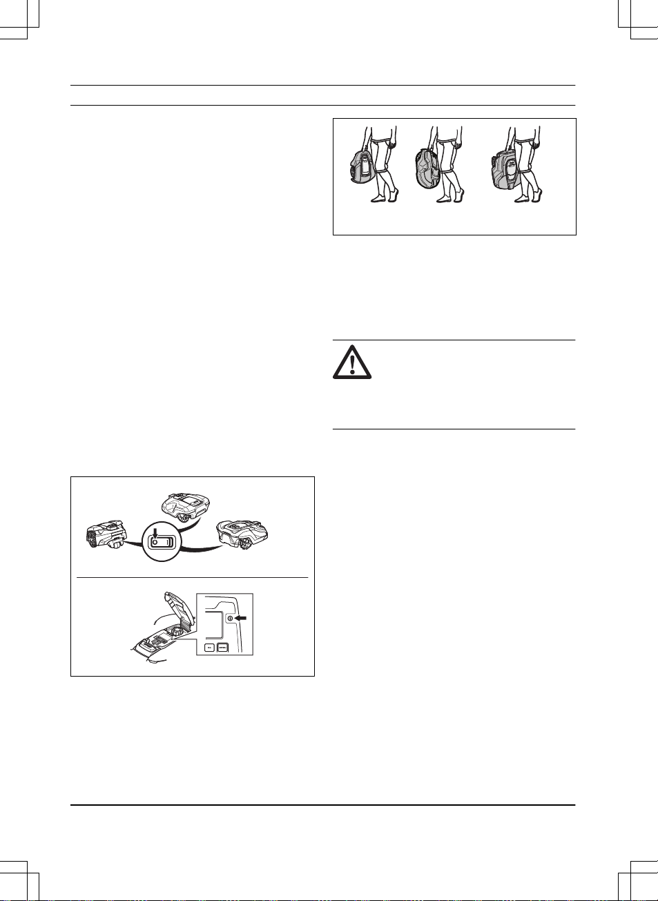
7.1.1 How to lift and move the product
To safely move from or within the work area:
1. Push the STOP button to stop the
product. If security is set to the medium or
high level the PIN code has to be entered.
The PIN code contains four digits and is
selected when you start the product for
the first time. Refer to complete
Operator's manual.
2. Switch off the product with the main
switch or the ON/OFF button.
105
305
310/315/315X
420/430X/440/450X
3. Carry the product by the handle under the
product with the blade disc away from the
body.
105 305/310
315/315X
420/430X
440/450X
7.2 Winter storage
7.2.1 The robotic lawn mower
The product must be cleaned carefully before
putting it away for the winter. Refer to
Cleaning on page 21
.
CAUTION: The battery must be
charged fully before winter storage.
If the battery is not fully charged it
can be damaged and in certain
cases be rendered useless.
Place the product in the charging station with
the hatch open until the battery icon in the
display shows that the battery is fully charged.
Switch off the product with the main switch or
the ON/OFF button.
Check the condition of wear items such as
blades and bearings in the rear wheel. Rectify
if necessary to make sure the product is in
good condition prior to next season.
Store the product standing on all wheels and
place it in a dry, frost-free environment,
preferably in the products’s original packaging.
You can also hang the product on a
Husqvarna original wall hanger. Contact your
Husqvarna representative for more information
about available wall hangers.
7.2.2 The charging station
Store the charging station and power supply
indoors. The boundary wire and the guide wire
can be left in the ground.
1. Disconnect the charging station's power
supply from the mains.
24 - Transportation, storage and
disposal
1418 - 004 - 10.03.2020
Page 25
2. Release the connector lock and pull the
connector out.
3. Disconnect the boundary and guide wire
contacts from the charging station.
The ends of the wires should be protected
from damp, for example by putting them in a
container with grease.
If it is not possible to store the charging station
indoors, the charging station must be
connected to the mains, the boundary wire
and the guide wires the entire winter.
7.3 Environmental information
The symbol on the Husqvarna
product indicates that this product
cannot be treated as domestic
waste. It should instead be left at a
suitable recycling centre to recycle
its electronic components and
batteries. The battery must be
removed from the product before it
is scrapped.
For disassembly of the battery see the
complete Operator's manual on Husqvarna’s
website.
For more detailed information about recycling
this product, contact your municipality, your
domestic waste service or the shop from
where you purchased the product.
8 Technical data
8.1 Automower® 105/305
Dimensions Automower® 105 Automower® 305
Length, cm / " 55 / 21.7 57 / 22.4
Width, cm / " 39 / 15.4 43 / 16.9
Height, cm / " 25 / 9.8 25 / 9.8
Weight, kg / lbs 6.9 / 15 9.4 / 21
1418 - 004 - 10.03.2020 Technical data - 25
Page 26

Electrical system Automower® 105 Automower® 305
Battery, Lithium-Ion 18.5 V/2.1 Ah Art.
No.
586 57 62-02 584 85 28-01, 584 85 28-02
Battery, Lithium-Ion 18 V/2.0 Ah Art.
No.
586 57 62-03 584 85 28-03, 590 21 42-02,
593 11 40-01, 593 11 40-02
Battery, Lithium-Ion 18.25 V/2.0 Ah
Art. No.
586 57 62-04
Power supply, V/28 V DC 100-240 100-240
Low voltage cable length, m / ft 5 / 16.4
Mean energy consumption at maximum use
5 kWh/month for a work
area of 600 m2 /
0.15 acre
5 kWh/month for a work
area of 600 m2 / 0.15 acre
Charging current, A DC 1.3 1.3
Type of Power Supply Unit FW7312, ADP-40BR ADP-40EW, ADP-40BR,
FW7312
Average mowing time, min 65 60
Average charging time, min 50 60
Boundary wire antenna Automower®
105
Automower®
305
Operating Frequency Band, Hz 300-80000 300-80000
Maximum Radio-frequency power,
mW @60m
13
<25 <25
Noise emissions measured in the environment as sound power
14
Automower® 105 Automower® 305
Measured sound power noise level,
dB (A)
58 58
Guaranteed sound power noise level,
dB (A)
61 59
Sound pressure noise level at the operator’s ear, dB (A)
15
47 47
13
Maximum active output power to antennas in the frequency band in which the radio equipment operates.
14
Noise emissions in the environment measured as sound power (Lwa) in conformity with EC
directive 2000/14/EC and New South Wales legislation (Protection of the Environment Operations Regulation 2017, Noise Control). The guaranteed sound power level includes variation in production as well as variation from the test code with 1-3 dB(A). Noise emission
data can be found on the rating label and in the Technical data chapter.
15
Sound pressure noise uncertainties KpA, 2-4 dB (A)
26 - Technical data 1418 - 004 - 10.03.2020
584 85 28-04, 590 21 42-03
5 / 16.4
Page 27
Mowing Automower® 105 Automower® 305
Cutting system 3 pivoted cutting blades
Blade motor speed, rpm 2900 2200
Power consumption during cutting, W
+/- 20 %
20 25
Cutting height, cm / " 2-5 / 0.8-2.0 2-5 / 0.8-2.0
Cutting width, cm / " 17 / 6.7 22 / 8.7
Narrowest possible passage, cm / " 60 / 24 60 / 24
Maximum angle for work area, % 25 40
Maximum angle for boundary wire, % 15 15
Maximum length boundary wire, m / ft 400 / 1300 800 / 2600
Maximum length guide loop, m / ft 200 / 650 400 / 1300
Working capacity, m2 / acre, +/- 20% 600 / 0.15 600 / 0.15
IP-classification Automower® 105 Automower® 305
Robotic lawn mower IPX4 IPX5
Charging station IPX1 IPX1
Power supply IPX4 IPX4
8.2 Automower® 310/315/315X
Dimensions
Automower® 310
Automower® 315
Automower
®
315X
Length, cm / " 63 / 24.8 63 / 24.8 63 / 24.8
Width, cm / " 51 / 20.1 51 / 20.1 51 / 20.1
Height, cm / " 25 / 9.8 25 / 9.8 25 / 9.8
Weight, kg / lbs 9.2 / 20 9.2 / 20 10.1 / 22
1418 - 004 - 10.03.2020 Technical data - 27
Page 28

Electrical system Automow-
er® 310
Automower® 315
Automower
®
315X
Battery, Lithium-Ion 18.5 V/2.1 Ah Art. No. 584 85
28-01, 584
85 28-02
584 85
28-01, 584
85 28-02
584 85
28-01, 584
85 28-02
Battery, Lithium-Ion 18 V/2.0 Ah Art. No. 584 85
28-03, 590
21 42-02,
593 11
40-01, 593
11 40-02
584 85
28-03, 590
21 42-02,
593 11
40-01, 593
11 40-02
584 85
28-03, 590
21 42-02,
593 11
40-01, 593
11 40-02
Battery, Lithium-Ion 18.25 V/2.0 Ah Art. No. 584 85
28-04, 590
21 42-03
584 85
28-04, 590
21 42-03
584 85
28-04, 590
21 42-03
Power supply, V/28 V DC 100-240 100-240 100-240
Low voltage cable length, m / ft 10 / 33 10 / 33 10 / 33
Mean energy consumption at maximum use 8 kWh/
month for a
work area of
1000 m2 /
0.25 acre
10 kWh/
month for a
work area of
1500 m2 /
0.37 acre
10 kWh/
month for a
work area of
1600 m2 /
0.4 acre
Charging current, A DC 1.3 1.3 1.3
Type of Power Supply Unit FW7312,
ADP-40BR
FW7312,
ADP-40BR
FW7312,
ADP-40BR
Average mowing time, min 70 70 70
Average charging time, min 60 60 60
Boundary wire antenna Automow-
er® 310
Automower® 315
Automower
®
315X
Operating Frequency Band, Hz 300-80000 300-80000 300-80000
Maximum Radio-frequency power, mW @60m
16
<25 <25 <25
16
Maximum active output power to antennas in the frequency band in which the radio equipment operates.
28 - Technical data 1418 - 004 - 10.03.2020
Page 29

Noise emissions measured in the environment as
sound power
17
Automower® 310
Automower® 315
Automower
®
315X
Measured sound power noise level, dB (A) 58 58 58
Guaranteed sound power noise level, dB (A) 60 60 60
Sound pressure noise level at the operator’s ear, dB
(A)
18
47 47 47
Mowing Automow-
er® 310
Automower® 315
Automower
®
315X
Cutting system 3 pivoted cutting blades
Blade motor speed, rpm 2300 2300 2300
Power consumption during cutting, W +/- 20 % 25 25 25
Cutting height, cm / " 2-6 / 0.8-2.4 2-6 / 0.8-2.4 2-6 / 0.8-2.4
Cutting width, cm / " 22 / 8.7 22 / 8.7 22 / 8.7
Narrowest possible passage, cm / " 60 / 24 60 / 24 60 / 24
Maximum angle for work area, % 40 40 40
Maximum angle for boundary wire, % 15 15 15
Maximum length boundary wire, m / ft 800 / 2600 800 / 2600 800 / 2600
Maximum length guide loop, m / ft 400 / 1300 400 / 1300 400 / 1300
Working capacity, m2 / acre, +/- 20% 1000 / 0.25 1500 / 0.37 1600 / 0.4
IP-classification Automow-
er® 310
Automower® 315
Automower
®
315X
Robotic lawn mower IPX4 IPX4 IPX4
Charging station IPX1 IPX1 IPX1
Power supply IPX4 IPX4 IPX4
17
Noise emissions in the environment measured as sound power (Lwa) in conformity with EC
directive 2000/14/EC and New South Wales legislation (Protection of the Environment Operations Regulation 2017, Noise Control). The guaranteed sound power level includes variation in production as well as variation from the test code with 1-3 dB(A). Noise emission
data can be found on the rating label and in the Technical data chapter.
18
Sound pressure noise uncertainties KpA, 2-4 dB (A)
1418 - 004 - 10.03.2020 Technical data - 29
Page 30

8.3 Automower® 420/430X/440/450X
Dimensions Automow-
er® 420
Automower
®
430X
Automower® 440
Automower
®
450X
Length, cm / " 72 / 28.3 72 / 28.3 72 / 28.3 72 / 28.3
Width, cm / " 56 / 22.0 56 / 22.0 56 / 22.0 56 / 22.0
Height, cm / " 31 / 12.2 31 / 12.2 31 / 12.2 31 / 12.2
Weight, kg / lbs 11.5 / 25 13.2 / 29 12 / 27 13.9 / 31
Electrical system Automow-
er® 420
Automower® 430X
Automower
®
440
Automower
®
450X
Battery, Lithium-Ion 18.5 V/4.0 Ah
Art. No.
580 68
33-02
Battery, Lithium-Ion 18 V/4.0 Ah Art.
No.
580 68
33-03, 593
11 41-02,
593 11
42-01
Battery, Lithium-Ion 18.25 V/4.0 Ah
Art. No.
580 68
33-04, 593
11 41-03,
593 11
42-02
Battery, Lithium-Ion 18 V/5.2 Ah Art.
No.
588 14 64-01
(2 pcs.) 5.2
Ah/battery
Battery, Lithium-Ion 18 V/5.0 Ah Art.
No.
593 11
84-01, 593
11 85-01
588 14 64-02,
593 11 84-01,
593 11 85-01
(2 pcs.) 5.0
Ah/battery
593 11
84-01, 593
11 85-01
(2 pcs.) 5.0
Ah/battery
Battery, Lithium-Ion 18 V/4.9 Ah Art.
No.
593 11
84-02, 593
11 85-02
588 14 64-03,
593 11 84-02,
593 11 85-02
(2 pcs.) 4.9
Ah/battery
593 11
84-02, 593
11 85-02
(2 pcs.) 4.9
Ah/battery
Power supply, V/28 V DC 100-240 100-240 100-240 100-240
Low voltage cable length, m / ft 10 / 33 10 / 33 10 / 33 10 / 33
30 - Technical data 1418 - 004 - 10.03.2020
Page 31

Electrical system Automow-
er® 420
Automower® 430X
Automower
®
440
Automower
®
450X
Mean energy consumption at maximum use
17 kWh/
month for a
work area
of
2200 m2 /
0.55 acre
18 kWh/
month for a
work area of
3200 m2 /
0.8 acre
20 kWh/
month for a
work area of
4000 m2 /
1 acre
23 kWh/
month for a
work area of
5000 m2 /
1.25 acres
Charging current, A DC 2.2 4.2 7 7
Type of Power Supply Unit ADP-60JR,
FW7438
FW7448,
ADP-120DR
FW7458/28/D
, ADP-200JR
FW7458/28/
D,
ADP-200JR
Average mowing time, min 75 145 290 270
Average charging time, min 50 50 60 60
Boundary wire antenna Automow-
er® 420
Automower
®
430X
Automower® 440
Automower
®
450X
Operating Frequency Band, Hz 300-80000 300-80000 300-80000 300-80000
Maximum Radio-frequency power,
mW @60m
19
<25 <25 <25 <25
Noise emissions measured in the environment as sound power
20
Automower® 420
Automower
®
430X
Automower® 440
Automower
®
450X
Measured sound power noise level,
dB (A)
57 57 56 58
Guaranteed sound power noise level 58 58 56 59
Sound pressure noise level at the operator’s ear, dB (A)
21
46 46 45 47
19
Maximum active output power to antennas in the frequency band in which the radio equipment operates.
20
Noise emissions in the environment measured as sound power (Lwa) in conformity with EC
directive 2000/14/EC and New South Wales legislation (Protection of the Environment Operations Regulation 2017, Noise Control). The guaranteed sound power level includes variation in production as well as variation from the test code with 1-3 dB(A). Noise emission
data can be found on the rating label and in the Technical data chapter.
21
Sound pressure noise uncertainties KpA, 2-4 dB (A)
1418 - 004 - 10.03.2020 Technical data - 31
Page 32

Mowing Automow-
er® 420
Automower
®
430X
Automower® 440
Automower
®
450X
Cutting system 3 pivoted cutting blades
Blade motor speed, rpm 2300 2300 2300 2300
Power consumption during cutting, W
+/- 20 %
30 30 30 35
Cutting height, cm / " 2-6 / 0.8-2.4 2-6 / 0.8-2.4 2-6 / 0.8-2.4 2-6 / 0.8-2.4
Cutting width, cm / " 24 / 9.4 24 / 9.4 24 / 9.4 24 / 9.4
Narrowest possible passage, cm / " 60 / 24 60 / 24 60 / 24 60 / 24
Maximum angle for work area, % 45 45 45 45
Maximum angle for boundary wire, % 15 15 15 15
Maximum length boundary wire, m / ft 800 / 2600 800 / 2600 800 / 2600 800 / 2600
Maximum length guide loop, m / ft 400 / 1300 400 / 1300 400 / 1300 400 / 1300
Working capacity, m2 / acre(s), +/20%
2200 / 0.55 3200 / 0.8 4000 / 1 5000 / 1.25
IP-classification Automow-
er® 420
Automower
®
430X
Automower® 440
Automower
®
450X
Robotic lawn mower IPX4 IPX4 IPX4 IPX4
Charging station IPX1 IPX1 IPX1 IPX1
Power supply IPX4 IPX4 IPX4 IPX4
Frequency Band Support
Bluetooth® Frequency range 2400.0-2483.5 MHz
Automower® Connect 2G GSM 850 MHz
E-GSM 900 MHz
DCS 1800 MHz
PCS 1900 MHz
Automower® Connect 3G Band 19 (800 MHz)
Band 5 (850 MHz)
Band 8 (900 MHz)
Band 2 (1900 MHz)
Band 1 (2100 MHz)
32 - Technical data 1418 - 004 - 10.03.2020
Page 33

Frequency Band Support
Automower® Connect 4G Band 12 (700 MHz)
Band 17 (700 MHz)
Band 28 (700 MHz)
Band 13 (700 MHz)
Band 20 (800 MHz)
Band 26 (850 MHz)
Band 5 (850 MHz)
Band 19 (850 MHz)
Band 8 (900 MHz)
Band 4 (1700 MHz)
Band 3 (1800 MHz)
Band 2 (1900 MHz)
Band 25 (1900 MHz)
Band 1 (2100 MHz)
Band 39 (1900 MHz)
Power Class
Bluetooth® Output power 8 dBM
Automower® Connect 2G Power Class 4 (for GSM/E-GSM) 33 dBm
Power Class 1 (for DCS/PCS) 30 dBm
Power Class E2 (for GSM/E-GSM
bands)
27 dBm
Power Class E2 (for DCS/PCS
bands)
26 dBm
Automower® Connect 3G Power Class 3 24 dBm
Automower® Connect 4G Power Class 3 23 dBm
Husqvarna AB does not guarantee full compatibility between the product and other types of
wireless systems such as remote controls, radio transmitters, hearing loops, underground electric
animal fencing or similar.
The products are made in England or the Czech Republic. See information on the rating plate.
Refer to
Introduction on page 2
1418 - 004 - 10.03.2020
Technical data - 33
Page 34

8.4 Registered trademarks
The
Bluetooth
®
word mark and logos are registered trademarks owned by
Bluetooth SIG, inc.
and any use of such marks by Husqvarna is under license.
9 Warranty
9.1 Warranty terms
Husqvarna warranty covers this product's
functionality for a period of 2 years from date
of purchase. The warranty covers serious
faults relating to materials or manufacturing
faults. Within the warranty period, we will
replace the product or repair it at no charge if
the following terms are met:
• The product and the charging station may
only be used in compliance with the
instructions in this Operator’s Manual.
This manufacturer's warranty does not
affect warranty entitlements against the
dealer/retailer.
• End-users or non-authorized third parties
must not attempt to repair the product.
Examples of faults which are not included in
the warranty:
• Damage caused by water seepage from
using a high-pressure washer, or from
being submerged under water, for
example when heavy rain forms pools of
water.
• Damage caused by lightning.
• Damage caused by improper battery
storage or battery handling.
• Damage caused by using a battery that is
not a Husqvarna original battery.
• Damage caused by not using Husqvarna
original spare parts and accessories,
such as blades and installation material.
• Damage to the loop wire.
• Damage caused by non-authorized
changing or tampering with the product or
its power supply.
The blades and wheels are seen as
disposable and are not covered by the
warranty.
If an error occurs with your Husqvarna
product, please contact Husqvarna customer
service for further instructions. Please have
the receipt and the product’s serial number at
hand when contacting Husqvarna customer
service.
10 EC Declaration of Conformity
10.1 EC Declaration of Conformity
Husqvarna AB, SE-561 82 Huskvarna,
Sweden, tel: +46-36-146500, declares that the
Robotic lawn mowers Husqvarna Automower
®
105, Husqvarna Automower® 305, Husqvarna
Automower® 310, Husqvarna Automower
®
315, Husqvarna Automower® 315X,
Husqvarna Automower® 420, Husqvarna
Automower® 430X, Husqvarna Automower
®
440 and Husqvarna Automower® 450X with
serial numbers dating 2019 week 40 and
onwards (the year and week is clearly stated
on the rating plate, followed by the serial
number), comply with the requirements of the
COUNCIL’S DIRECTIVE:
• Directive “relating to machinery”
2006/42/EC.
• Particular requirements for robotic
battery powered electrical lawn
mowers EN 50636-2-107: 2015.
• Electromagnetic fields EN 62233:
2008.
• Directive on ”restriction of use of certain
hazardous substances” 2011/65/EU.
34 - Warranty 1418 - 004 - 10.03.2020
Page 35

• The following standard is applied: EN
50581:2012
• Directive “relating to noise emissions from
outdoor equipment” 2000/14/EC. See
also
Technical data on page 25
for
information regarding noise emissions
and the cutting width.
For Husqvarna Automower® 105
(certificate 01/901/176), Husqvarna
Automower® 305 (certificate 01/901/322),
Husqvarna Automower® 310/315
(certificate 01/901/225), Husqvarna
Automower® 315X (certificate
01/901/286) and Husqvarna Automower
®
420/430X/440/450X (certificate
01/901/201): The notified body RISE SMP
Svensk Maskinprovning AB, Box 7035,
SE-750 07 Uppsala, Sweden, has issued
a report regarding the assessment of
conformity according to annex VI to the
Council’s Directive of May 8, 2000
“relating to noise emissions into the
environment” 2000/14/EC.
• Directive “relating to radio equipment”
2014/53/EU. Type examination certificate
is issued for examination to Directive
2014/53/EU. Type examination certificate
number for Husqvarna Automower® 105
is SC1110-17. The following standards
have been applied:
• ETSI EN 303 447 V1.1.1
Electromagnetic compatibility:
• ETSI EN 301 489-1 V2.2.0
• EN 61000-6-1:2007
• EN 61000-6-3:2007/A1:2011
For Husqvarna Automower® 315X,
Husqvarna Automower® 430X and
Husqvarna Automower® 450X equipped
with the Automower® Connect module
also:
• ETSI EN 301 489-19 V2.1.0
• ETSI EN 301 489-52 V1.1.1
• ETSI EN 301 511 V12.5.1
• ETSI EN 301 908-2 V11.1.1
For
Husqvarna Automower® 305, Husqvarna
Automower® 310, Husqvarna Automower
®
315, Husqvarna Automower® 315X, Husqvarna Automower® 420, Husqvarna Automower® 430X,Husqvarna Automower® 440
and Husqvarna Automower® 450X equipped
with Bluetooth® also:
• ETSI EN 300 328 V2.1.1
• ETSI EN 301 489-17 V3.1.1
Husqvarna 2019-12-12
Lars Roos
Global R&D Director, Electric category
(Authorized representative for Husqvarna AB
and responsible for technical documentation.)
1418 - 004 - 10.03.2020
EC Declaration of
Conformity - 35
Page 36

Inhalt
12 Einleitung......................................................36
13 Sicherheit......................................................44
14 Installation.................................................... 48
15 Betrieb.......................................................... 53
16 Wartung........................................................57
17 Fehlerbehebung........................................... 59
18 Transport, Lagerung und Entsorgung...........60
19 Technische Angaben....................................62
20 Gewährleistung.............................................71
21 EG-Konformitätserklärung............................72
11 Einleitung
11.1 Einleitung
Seriennummer:
PIN-Code:
Die Seriennummer findet sich auf dem Typenschild und auf dem Karton des Geräts.
• Verwenden Sie die Seriennummer, um Ihr Gerät auf www.husqvarna.com zu registrieren.
11.2 Support
Wenden Sie sich an Ihren Husqvarna
Servicehändler, um Support für das Gerät zu
erhalten.
11.2.1 Vollständige Bedienungsanleitung
Eine vollständige Bedienungsanleitung
befindet sich auf der Husqvarna Website
www.husqvarna.com. Diese ist ausführlicher
und enthält weitere Informationen, z. B.
Anweisungen zur Installation, Wartung,
Fehlerbehebung und Menüstruktur.
11.2.2 Gerätebeschreibung
Hinweis: Husqvarna aktualisiert regelmäßig
das Erscheinungsbild und die Funktion der
Geräte. Siehe
Support auf Seite 36
.
Das Gerät ist ein Mähroboter. Das Gerät ist
akkubetrieben und schneidet das Gras
automatisch. Das Aufsammeln des Grases ist
nicht erforderlich.
Der Bediener legt die Betriebseinstellungen
mit den Tasten auf der Tastatur fest. Das
Display zeigt die ausgewählten und möglichen
Betriebseinstellungen und den Betriebsmodus
des Geräts an.
Das Begrenzungskabel und das Leitkabel
steuern die Bewegungen des Geräts innerhalb
des Arbeitsbereichs.
11.2.2.1 Automower® Connect
Automower® Connect ist eine mobile
Anwendung, die es ermöglicht, die
Betriebseinstellungen per Fernzugriff
auszuwählen. Siehe
Konnektivität auf Seite
55
.
11.3 Kapazität
Die Größe der Fläche, die das Gerät
bearbeiten kann, hängt hauptsächlich vom
Zustand der Klingen sowie von Grasart,
Wachstum und Feuchtigkeit ab. Darüber
hinaus ist auch die Form des Gartens von
entscheidender Bedeutung. Wenn der Garten
hauptsächlich aus einer freien Rasenfläche
besteht, kann das Gerät pro Stunde mehr
mähen, als wenn der Garten aus
verschiedenen kleinen Rasenflächen mit
vielen Bäumen, Blumenbeeten und Passagen
besteht. Informationen zur Arbeitskapazität
finden Sie unter
Technische Angaben auf
Seite 62
.
Optimale Mähergebnisse werden erzielt, wenn
das Gerät das Gras bei trockenem Wetter
mähen kann. Das Gerät kann auch bei Regen
36 - Einleitung
1418 - 004 - 10.03.2020
Page 37

mähen. Nasses Gras bleibt jedoch leichter
hängen. Außerdem steigt das Risiko, dass
das Gerät an steilen Hängen ins Rutschen
kommt. Die Klingen müssen für ein optimales
Mähergebnis stets in gutem Zustand sein. Um
die Klingen solange wie möglich scharf zu
halten, ist es wichtig, dass sich keine Äste,
kleinen Steine oder anderen Gegenstände auf
dem Rasen befinden. Tauschen Sie die
Klingen regelmäßig aus. Siehe
Austausch der
Klingen auf Seite 58
.
11.4 Bewegungsmuster
Das Bewegungsmuster des Geräts ist zufällig.
Dies bedeutet, dass der Rasen gleichmäßig
ohne Mählinien gemäht wird.
11.5 Arbeitsmethode
Automower® 315X/430X/450X verwendet
GPS-unterstützte Navigation zum Mähen und
beginnt an einer Stelle im Garten, an der er
längere Zeit nicht gemäht hat. Bei den
anderen Modellen müssen Sie unter
Umständen Fernstarteinstellungen festlegen,
um einen gleichmäßigen Rasenschnitt
sicherzustellen; weitere Informationen dazu
finden Sie in der vollständigen
Bedienungsanleitung auf der Website von
Husqvarna.
Wenn das Gerät an ein Hindernis stößt oder
sich dem Begrenzungskabel nähert, dreht es
um und schlägt eine neue Richtung ein.
Mittels Sensoren vorne und hinten erkennt
das Gerät, wenn es sich dem
Begrenzungskabel nähert. Die Vorderseite
des Geräts ragt vor dem Drehen immer etwas
über das Begrenzungskabel hinaus. Der
Abstand kann geändert werden, um der
Installation, falls erforderlich, angepasst zu
werden.
Die Taste STOP oben auf dem Gerät dient
hauptsächlich dazu, es anzuhalten, wenn es
in Betrieb ist. Wenn die Taste STOP gedrückt
wird, öffnet sich die Abdeckung, unter der sich
das Bedienfeld befindet. Die Taste STOP
bleibt eingerastet, bis die Abdeckung wieder
geschlossen wird. Dies dient zusammen mit
der Taste START als Startsperre.
Hinweis: Drücken Sie immer die Taste
START, bevor Sie die Abdeckung zum Starten
des Geräts schließen. Wenn die Taste START
nicht gedrückt wurde, ist ein Warnton zu hören
und das Gerät startet nicht.
Hinweis: Wenn das Gerät zum ersten Mal
gestartet wird, beginnt eine Startsequenz mit
einer Reihe von Grundeinstellungen, siehe
„Grundeinstellungen vornehmen“
in der
vollständigen Bedienungsanleitung auf der
Husqvarna Website.
11.6 Suchen der Ladestation
Um die Ladestation zu finden, kann der
Automower® 305/310/315/315X/420/430X/
440/450X auf bis zu drei verschiedene
1418 - 004 - 10.03.2020
Einleitung - 37
Page 38

Suchmethoden eingestellt werden. Das Gerät
kombiniert diese 3 Suchmethoden
automatisch, um die Ladestation so schnell
wie möglich zu finden und dabei unnötige
Spurenbildung zu vermeiden. Der
Automower® 105 folgt immer dem Leitkabel
zur Ladestation.
11.7 Geräteübersicht Automower® 105
1
32
17
26
6
5
4
13
14
12
21
25
19
24
20
23
18
8
10
11
7
22
15
28
16
9
27
Die Zahlen in der Darstellung stehen für:
1. Gehäuse
2. Abdeckung für Display, Tastatur und
Schnitthöheneinstellung
3. Stopptaste
4. Kontaktbleche
5. LED für Funktionsprüfung der
Ladestation, des Begrenzungskabels und
des Leitkabels
6. Ladestation
7. Griff
8. Akku-Abdeckung
9. Klingenteller
10. Gleitplatte
11. Chassisgehäuse mit Elektronik, Akku und
Motoren
12. Hauptschalter
13. Hinterrad
38 - Einleitung 1418 - 004 - 10.03.2020
Page 39

14. Ladeplatten
15. Tastatur
16. Display
17. Schleifenkabel für Begrenzungskabel und
Leitkabel
18. Verbinder für das Schleifenkabel
19. Haken
20. Verbinder für das Schleifenkabel
21. Schrauben zum Befestigen der
Ladestation
22. Klingen
23. Bedienungsanleitung und Kurzanleitung
24. Lineal für die Installation des
Begrenzungskabels (das Lineal wird an
der Perforationslinie aus dem Karton
herausgelöst)
25. Netzteil (Aussehen kann je nach Markt
variieren)
26. Niederspannungskabel
27. Alarm-Aufkleber
28. Typenschild (inkl.
Geräteidentifikationscode)
11.8 Geräteübersicht Automower® 305
1
2
4
5
6
7
9
15
14
18
16
19
17
13
11
12
24
26
25
27
28
29
30
8
20
23
22
21
3
10
Die Zahlen in der Darstellung stehen für:
1. Gehäuse
2. Abdeckung für Tastatur, Display und
Schnitthöheneinstellung
3. Stopptaste
4. Hinterräder
5. Vorderräder
6. Klingenteller
7. Gleitplatte
8. Kontaktbleche
9. LED für Funktionsprüfung von
Ladestation und Begrenzungskabel
10. Ladestation
11. Display
12. Tastatur
13. Taste EIN/AUS
1418 - 004 - 10.03.2020 Einleitung - 39
Page 40

14. Typenschild (inkl.
Geräteidentifikationscode)
15. Schnitthöheneinstellung
16. Wartungswerkzeug
17. Schneidsystem
18. Chassisgehäuse mit Elektronik, Akku und
Motoren
19. Griff
20. Schleifenkabel für Begrenzungskabel und
Leitkabel
22
21. Verbinder für das Schleifenkabel
23
22. Haken
24
23. Verbinder für das Schleifenkabel
25
24. Schrauben zum Befestigen der
Ladestation
25. Netzteil (Aussehen kann je nach Markt
variieren)
26. Lineal für die Installation des
Begrenzungskabels (das Lineal wird an
der Perforationslinie aus dem Karton
herausgelöst)
27. Bedienungsanleitung und Kurzanleitung
28. Zusätzliche Klingen
29. Niederspannungskabel
30. Alarm-Aufkleber
11.9 Geräteübersicht Automower® 310/315/315X
1
12
13
14
2
3
4
5
6
9
8
11
15
10
1816
17
22
20
19
21
25
26
27
23
28
29
30
31
7
24
Die Zahlen in der Darstellung stehen für:
1. Gehäuse
2. Abdeckung für Schnitthöheneinstellung
3. Abdeckung für Display und Tastatur
22
Teil des Installations-Kits, das separat erhältlich ist.
23
Teil des Installations-Kits, das separat erhältlich ist.
24
Teil des Installations-Kits, das separat erhältlich ist.
25
Teil des Installations-Kits, das separat erhältlich ist.
40 - Einleitung 1418 - 004 - 10.03.2020
Page 41

4. Stopptaste
5. Abnehmbare Abdeckung
6. Hinterräder
7. Vorderräder
8. Schnitthöheneinstellung
9. Kontaktbleche
10. LED für Funktionsprüfung von
Ladestation und Begrenzungskabel
11. Ladestation
12. Typenschild (inkl.
Geräteidentifikationscode)
13. Display
14. Tastatur
15. Schneidsystem
16. Chassisgehäuse mit Elektronik, Akku und
Motoren
17. Griff
18. Hauptschalter
19. Klingenteller
20. Gleitplatte
21. Netzteil (Aussehen kann je nach Markt
variieren)
22. Schleifenkabel für Begrenzungskabel und
Leitkabel
26
23. Verbinder für das Schleifenkabel
27
24. Haken
28
25. Verbinder für das Schleifenkabel
29
26. Schrauben zum Befestigen der
Ladestation
27. Lineal für die Installation des
Begrenzungskabels (das Lineal wird an
der Perforationslinie aus dem Karton
herausgelöst)
28. Bedienungsanleitung und Kurzanleitung
29. Zusätzliche Klingen
30. Niederspannungskabel
31. Alarm-Aufkleber
26
Teil des Installations-Kits, das separat erhältlich ist.
27
Teil des Installations-Kits, das separat erhältlich ist.
28
Teil des Installations-Kits, das separat erhältlich ist.
29
Teil des Installations-Kits, das separat erhältlich ist.
1418 - 004 - 10.03.2020 Einleitung - 41
Page 42

11.10 Geräteübersicht Automower® 420/430X/440/450X
Automower 420/440 Automower 430X Automower 450X
23
22
28
24
25
27
26
21
31
32
30
29
4
5
2
3
1
19
20
9
11
10
12
13
14
15
16
17
6
7
8
18
Die Zahlen in der Darstellung stehen für:
1. Gehäuse
2. Abdeckung für Display und Tastatur
3. Stopptaste
4. Vorderräder
5. Hinterräder
6. Ultraschallsensoren
7. Scheinwerfer
8. Abnehmbare Abdeckung
9. Typenschild (inkl.
Geräteidentifikationscode)
10. Display
11. Tastatur
12. Schneidsystem
13. Chassisgehäuse mit Elektronik, Akku und
Motoren
14. Hauptschalter
15. Griff
16. Klingenteller
17. Gleitplatte
18. Kontaktbleche
19. LED für Funktionsprüfung von
Ladestation und Begrenzungskabel
20. Ladestation
21. Netzteil (Aussehen kann je nach Markt
variieren)
22. Kabelmarkierungen
23. Lineal für die Installation des
Begrenzungskabels (das Lineal wird an
der Perforationslinie aus dem Karton
herausgelöst)
24. Schrauben zum Befestigen der
Ladestation
42 - Einleitung
1418 - 004 - 10.03.2020
Page 43

25. Bedienungsanleitung und Kurzanleitung
26. Alarm-Aufkleber
27. Zusätzliche Klingen
28. Niederspannungskabel
29. Verbinder für das Schleifenkabel
30
30. Schleifenkabel für Begrenzungskabel und
Leitkabel
31
31. Haken
32
32. Verbinder für das Schleifenkabel
33
11.11 Symbole auf dem Gerät
Diese Symbole befinden sich auf dem Gerät.
Lesen Sie sich die entsprechenden
Anweisungen sorgfältig durch.
WARNUNG: Lesen Sie
die Gebrauchsanweisung, bevor Sie das Gerät in Betrieb nehmen.
WARNUNG: Deaktivieren Sie das Gerät, bevor
Sie daran arbeiten oder
es anheben.
WARNUNG: Halten Sie
einen sicheren Abstand
zum Gerät, wenn es in
Betrieb ist. Halten Sie
Hände und Füße von
den rotierenden Klingen
fern.
WARNUNG: Setzen
oder stellen Sie sich
nicht auf das Gerät. Halten Sie mit Ihren Händen und Füßen stets einen sicheren Abstand
zum Gerät.
Reinigen Sie das Gerät
weder mit einem Hochdruckreiniger noch unter
fließendem Wasser.
Verwenden Sie ein abnehmbares Netzteil wie
auf dem Gerätetypenschild neben dem Symbol angegeben.
Dieses Gerät erfüllt die geltenden
CE-Richtlinien.
Lärmemission. Die
Lärmemissionen des Geräts
werden unter
Technische
Angaben auf Seite 62
und auf
dem Typenschild angegeben.
30
Teil des Installations-Kits, das separat erhältlich ist.
31
Teil des Installations-Kits, das separat erhältlich ist.
32
Teil des Installations-Kits, das separat erhältlich ist.
33
Teil des Installations-Kits, das separat erhältlich ist.
1418 - 004 - 10.03.2020 Einleitung - 43
Page 44

Es ist nicht zulässig, dieses Gerät
über den normalen Hausmüll zu
entsorgen. Stellen Sie sicher, dass
das Gerät in Übereinstimmung mit
den örtlich geltenden Regelungen
entsorgt wird.
Das Chassis enthält Bauteile, die
empfindlich gegenüber
elektrostatischer Entladung
(electrostatic discharge = ESD)
sind. Das Chassis muss
fachmännisch neu versiegelt
werden. Aus diesen Gründen
sollte das Chassis ausschließlich
von autorisierten
Servicetechnikern geöffnet
werden. Eine beschädigte
Versiegelung kann zu teilweisem
oder vollständigem Erlöschen der
Garantie führen.
Das Niederspannungskabel darf
weder gekürzt, verlängert noch
gespleißt werden.
Verwenden Sie keinen Trimmer in
der Nähe des
Niederspannungskabels. Gehen
Sie beim Trimmen von Kanten, in
deren Nähe sich die Kabel
befinden, vorsichtig vor.
11.12 Symbole am Akku
Lesen Sie die
Gebrauchsanweisung.
Werfen Sie den Akku nicht ins
Feuer und setzen Sie ihn keiner
Wärmequelle aus.
Tauchen Sie den Akku nicht in
Wasser.
11.13 Allgemeine Hinweise
Um das Lesen der Bedienungsanleitung zu
erleichtern, wird der Text folgendermaßen
dargestellt:
• Texte, die
kursiv
dargestellt sind, werden
entweder auf dem Display des Geräts
angezeigt oder es sind Verweise auf
einen anderen Abschnitt in der
Bedienungsanleitung.
• Fett gedruckter Text steht für die Tasten
der Tastatur des Geräts.
• Text in
GROSSBUCHSTABEN
und
kursiver
Schrift gibt die verschiedenen für
das Gerät verfügbaren Betriebsmodi an.
12 Sicherheit
12.1 Sicherheitsdefinitionen
Warnungen, Vorsichtsmaßnahmen und
Hinweise werden verwendet, um auf
besonders wichtige Teile der
Bedienungsanleitung hinzuweisen.
WARNUNG: Wird verwendet,
wenn bei Nichtbeachtung der
Anweisungen in diesem Handbuch
die Gefahr von Verletzung oder Tod
des Bedieners oder anderer
Personen besteht.
ACHTUNG: Wird verwendet,
wenn bei Nichtbeachtung der
Anweisungen in diesem Handbuch
die Gefahr von Schäden am Gerät,
an anderen Materialien oder in der
Umgebung besteht.
44 - Sicherheit 1418 - 004 - 10.03.2020
Page 45

Hinweis: Für weitere Informationen, die in
bestimmten Situationen nötig sind.
12.1.1 WICHTIG. VOR GEBRAUCH
SORGFÄLTIG DURCHLESEN. ZUM
SPÄTEREN NACHSCHLAGEN
AUFBEWAHREN
Der Bediener ist für Unfälle und Gefahren verantwortlich, die an
anderen Personen oder deren Eigentum entstehen.
Der Gebrauch des Geräts durch Personen (einschließlich
Kindern), die über eingeschränkte körperliche, sensorische oder
geistige Fähigkeiten verfügen (und somit kein sicherer Umgang mit
dem Gerät gewährleistet werden kann) oder denen es an der
erforderlichen Erfahrung und Kenntnis mangelt, ist untersagt,
sofern sie nicht von einer für ihre Sicherheit verantwortlichen
Person bei der Arbeit überwacht oder im Gebrauch des Geräts
zuvor geschult wurden.
Dieses Gerät kann von Kindern ab 8 Jahren sowie von Personen
mit eingeschränkten physischen, sensorischen oder psychischen
Fähigkeiten bzw. Personen ohne jegliche Erfahrung oder
Kenntnisse verwendet werden, wenn sie beaufsichtigt werden oder
ihnen die sichere Verwendung des Geräts ausführlich erklärt
wurde und sie sich der Gefahren bewusst sind. Unter Umständen
gelten gesetzlich vorgeschriebene Altersbeschränkungen für den
Bediener. Reinigung und Wartung dürfen von Kindern nicht ohne
Aufsicht durchgeführt werden.
Schließen Sie das Netzteil niemals an eine Steckdose an, wenn
Stecker oder Kabel beschädigt sind. Abgenutzte oder beschädigte
Kabel erhöhen das Risiko eines elektrischen Schlags.
Laden Sie die Batterie nur in der mitgelieferten Ladestation auf.
Eine inkorrekte Verwendung kann zu elektrischen Schlägen,
Überhitzung oder Austreten von ätzender Flüssigkeit aus der
Batterie führen. Spülen Sie bei Austritt von Elektrolyt mit Wasser/
1418 - 004 - 10.03.2020
Sicherheit - 45
Page 46

Neutralisationsmittel. Suchen Sie bei Kontakt mit den Augen
umgehend einen Arzt auf.
Verwenden Sie nur vom Hersteller empfohlene Originalakkus. Die
Gerätesicherheit kann nur bei der Verwendung von Originalakkus
gewährleistet werden. Verwenden Sie keine nicht
wiederaufladbaren Akkus.
Das Gerät muss bei der Akkuentnahme vom Stromnetz getrennt
sein.
WARNUNG: Das Gerät
kann bei
unsachgemäßem
Gebrauch eine Gefahr
darstellen.
WARNUNG: Benutzen
Sie das Gerät nicht,
wenn sich Personen,
insbesondere Kinder
oder Tiere, im
Arbeitsbereich befinden.
WARNUNG: Halten Sie
Hände und Füße von
den rotierenden Klingen
fern. Halten Sie mit Ihren
Händen und Füßen stets
einen sicheren Abstand
zum Gerät, solange es in
Betrieb ist.
WARNUNG: Suchen Sie
im Falle einer Verletzung
oder eines Unfalls einen
Arzt auf.
12.2 Verwendung
• Das Gerät darf nur mit der vom Hersteller
empfohlenen Ausstattung verwendet
werden. Andere Verwendungsarten sind
nicht zulässig. Die Anweisungen des
Herstellers hinsichtlich Betrieb, Wartung
und Reparatur sind genau einzuhalten.
• Bei Nutzung des Geräts im öffentlichen
Bereich müssen Warnschilder um den
Arbeitsbereich angebracht werden. Diese
Schilder müssen mit folgendem Text
versehen sein: Warnung! Automatischer
Rasenmäher! Halten Sie sich vom Gerät
fern! Kinder müssen beaufsichtigt
werden!
46 - Sicherheit
1418 - 004 - 10.03.2020
Page 47

WARNING!
Automatic lawnmower!
Keep away from the machine!
Supervise children!
I am a robotic lawnmower and I work here quietly
to keep the lawn in perfect condition.
I work 24/7 independently of weather conditions and do it
without releasing any exhaust emissions.
Stay a while and enjoy my work,
but please let me work in peace.
• Verwenden Sie die PARK-Funktion oder
schalten Sie das Gerät aus, wenn sich
Personen, insbesondere Kinder oder
Tiere, in der Nähe des Arbeitsbereichs
befinden. Es wird empfohlen, das Gerät
für den Betrieb in den Zeiten zu
programmieren, in denen in dem Bereich
keine Aktivitäten stattfinden, z. B. in der
Nacht. Beachten Sie, dass bestimmte
Tierarten, z. B. Igel, nachtaktiv sind. Sie
können möglicherweise durch das Gerät
verletzt werden.
• Das Gerät darf nur von Personen
betrieben, gewartet und repariert werden,
die mit dessen Eigenschaften und den
beim Gebrauch einzuhaltenden
Sicherheitsvorschriften bestens vertraut
sind. Lesen Sie die Betriebsanleitung
sorgfältig durch, und machen Sie sich mit
dem Inhalt vertraut, bevor Sie das Gerät
benutzen.
• Es ist nicht gestattet, das Originaldesign
des Geräts zu verändern. Alle
diesbezüglichen Veränderungen erfolgen
auf eigene Gefahr.
• Stellen Sie sicher, dass sich keine
Fremdkörper wie Steine, Äste, Werkzeug
oder Spielzeug auf dem Rasen befinden.
Die Klingen können beim Zusammenstoß
mit Fremdkörpern beschädigt werden.
Schalten Sie das Gerät immer mit dem
Hauptschalter oder der Taste ON/OFF
aus, bevor Sie eine Blockierung
entfernen. Prüfen Sie das Gerät auf
Schäden, bevor Sie es wieder in Betrieb
nehmen.
• Falls das Gerät beginnt, ungewöhnlich zu
vibrieren. Schalten Sie das Gerät stets
mittels des Hauptschalters oder der Taste
ON/OFF aus und prüfen Sie es auf
Schäden, bevor Sie es wieder in Betrieb
nehmen.
• Starten Sie das Gerät gemäß den
Anweisungen. Wenn das Gerät mit der
Taste ON/OFF aktiviert ist oder wenn der
Hauptschalter auf
1
gestellt ist, halten Sie
Hände und Füße von den rotierenden
Messern fern. Halten Sie Ihre Hände und
Füße von der Unterseite des Geräts fern.
• Berühren Sie niemals bewegliche
gefährliche Bauteile, wie z. B. den
Klingenteller, bevor diese vollständig zum
Stillstand gekommen sind.
• Heben Sie das Gerät nicht hoch und
tragen Sie es nicht herum, wenn es
eingeschaltet ist.
• Das Gerät darf nicht mit Personen oder
anderen Lebewesen kollidieren. Wenn
eine Person oder ein anderes Lebewesen
in den Fahrweg des Geräts gelangt, muss
es sofort angehalten werden.
• Legen Sie keine Gegenstände auf
Gehäuse oder Ladestation des Geräts.
• Das Gerät darf nicht mit beschädigtem
Schutz, Klingenteller oder Gehäuse
betrieben werden. Darüber hinaus darf es
auch nicht mit beschädigten Klingen,
Schrauben oder Kabeln betrieben
werden. Schließen Sie keine
1418 - 004 - 10.03.2020
Sicherheit - 47
Page 48

beschädigten Kabel an und berühren Sie
sie nicht, bevor sie von der
Stromversorgung getrennt wurden.
• Verwenden Sie das Gerät nicht, wenn der
Hauptschalter oder die Taste ON/OFF
nicht funktioniert.
• Schalten Sie das Gerät immer über den
Hauptschalter oder die Taste ON/OFF
aus, wenn es nicht verwendet wird. Das
Gerät kann nur gestartet werden, wenn
der Hauptschalter auf
1
gestellt oder die
Taste ON/OFF eingeschaltet ist und die
Anzeigeleuchte leuchtet. Der korrekte
PIN-Code muss ebenfalls eingegeben
werden, damit das Gerät gestartet
werden kann.
• Das Gerät darf nicht gleichzeitig mit
einem Rasensprenger eingesetzt werden.
Benutzen Sie die
Zeitplan
-Funktion, damit
Rasensprenger und Gerät nicht
gleichzeitig in Betrieb sind.
• Husqvarna übernimmt keine Garantie für
die vollständige Kompatibilität zwischen
dem Gerät und anderen kabellosen
Systemen wie Fernbedienungen,
Sendern, im Boden verlegten elektrischen
Umzäunungen von Viehweiden o. ä.
• Der integrierte Alarm ist sehr laut. Seien
Sie vorsichtig, insbesondere wenn das
Gerät im Innenbereich verwendet wird.
• Metallische Gegenstände im Boden (z. B.
Stahlbeton oder Anti-Maulwurfnetze)
können zum Anhalten des Mähers führen.
Die metallischen Gegenstände können
eine Interferenz mit dem Schleifensignal
verursachen, was zum Anhalten des
Mähers führen kann.
• Betriebs- und Lagertemperatur sind 0-50
°C / 32-122 °F. Temperaturbereich zum
Laden ist 0-45 °C / 32-113 °F. Zu hohe
Temperaturen können zu Schäden am
Gerät führen.
12.3 Sicherheit im Umgang mit Akkus
WARNUNG: Lithium-Ionen-Akkus
können explodieren oder Feuer
verursachen, wenn sie demontiert,
kurzgeschlossen oder Wasser,
Feuer oder hohen Temperaturen
ausgesetzt werden. Gehen Sie
vorsichtig vor, öffnen Sie den Akku
nicht und setzen Sie ihn keinen
elektrischen/mechanischen
Belastungen aus. Vermeiden Sie die
Lagerung der Batterien bei direkter
Sonneneinstrahlung.
Weitere Informationen zum Akku finden Sie
unter:
Akku auf Seite 57
13 Installation
13.1 Anschließen des Netzteils
Beachten Sie beim Platzieren des Netzteils
folgende Faktoren:
• Nahe der Ladestation
• Vor Regen geschützt
• Keine direkte Sonneneinstrahlung
WARNUNG: Das Gerät darf nur
mit einem Netzteil von Husqvarna
betrieben werden.
Verbinden Sie das Netzteil nur mit
Steckdosen, die mit einem
Erdschlusstrennschalter (RCD) ausgestattet
sind.
WARNUNG: Es besteht die
Gefahr von elektrischen Schlägen.
Verwenden Sie beim Anschluss des
Netzteils an die Steckdose einen
Erdschlusstrennschalter (RCD). Für
USA/KANADA: Verwenden Sie
Steckdosen der Klasse A mit FISchutz (RCD) und mit einem
Gehäuse, das sowohl mit
eingesetzter als auch entfernter
Verschlusskappe wetterfest ist.
48 - Installation 1418 - 004 - 10.03.2020
Page 49

WARNUNG: Komponenten des
Netzteils dürfen nicht verändert oder
manipuliert werden. Das
Niederspannungskabel darf weder
gekürzt noch verlängert werden.
Niederspannungskabel unterschiedlicher
Längen sind als Zubehör erhältlich.
WARNUNG: Netzkabel und
Verlängerungskabel müssen sich
außerhalb des Arbeitsbereichs
befinden, damit sie nicht zu
Schaden kommen.
WARNUNG: Das Netzteil darf
keinesfalls in einer Höhe montiert
werden, bei der es in Wasser
getaucht werden könnte
(Mindesthöhe 30 cm (12 Zoll) vom
Boden). Das Netzteil darf nicht auf
dem Boden platziert werden.
min 30 cm / 12”
WARNUNG: Trennen Sie die
Ladestation über den Stecker, bevor
Sie z. B. Reinigungsarbeiten
vornehmen oder das Schleifenkabel
reparieren.
WARNUNG: Passen Sie die
Schnitthöhe entsprechend an und
verlegen Sie das
Niederspannungskabel so, dass die
Messer am Messerteller dieses nicht
berühren können.
WARNUNG: Um das Risiko der
Beschädigung von elektrischen
Komponenten zu verringern, trennen
Sie bei Gewittergefahr alle
Verbindungen zur Ladestation
(Stromversorgung,
Begrenzungskabel und Leitkabel).
WARNUNG: Bedecken Sie das
Netzteil nicht. Kondenswasser kann
dem Netzteil schaden und das
Risiko eines Stromschlags erhöhen.
Weitere Hinweise zur korrekten Installation
finden Sie im Kapitel
Installation
in der
vollständigen Bedienungsanleitung auf der
Website www.husqvarna.com von Husqvarna.
13.2 Bedienfeld
Alle Befehle und Einstellungen für das Gerät
erfolgen über das Bedienfeld. Alle Funktionen
sind über eine Reihe von Menüs zugänglich.
Das Bedienfeld besteht aus einem Display
und einer Tastatur. Alle Informationen werden
auf dem Display angezeigt und alle Eingaben
erfolgen über die Tasten.
Hinweis: Die Texte auf dem Display werden
in der Bedienungsanleitung in Englisch, auf
der Anzeige des Geräts jedoch in der
ausgewählten Sprache angezeigt.
13.3 Display Automower® 105
Wenn die STOP-Taste gedrückt und die
Abdeckung geöffnet wurde, erscheint das
Bedienfenster. Uhrzeit, ausgewählter
Betriebsmodus, Anzahl der Mähstunden und
Akkustatus werden angezeigt.
1418 - 004 - 10.03.2020
Installation - 49
Page 50

• Die Uhrzeit entspricht der aktuellen Zeit.
• Das Datum zeigt den aktuellen Tag an.
• Die Anzahl der Betriebsstunden gibt die
Anzahl der Stunden an, die das Gerät seit
dem Herstellungstag in Betrieb gewesen
ist. Die Zeit, die das Gerät mit Mähen
oder Suchen nach der Ladestation
verbracht hat, wird als Betriebszeit
angerechnet.
•
AUTO, MAN
oder
HOME
zeigt den
ausgewählten Betriebsmodus an.
• Der Akkustatus zeigt die verbleibende
Akkuladung an.
• Das ECO-Symbol wird angezeigt, wenn
sich das Gerät im
ECO-Modus
befindet.
• Das Uhrsymbol wird angezeigt, wenn der
Timer aktiviert ist. Das Uhrensymbol ist
schwarz, wenn das Gerät aufgrund der
Timer-Einstellung nicht mähen darf.
• Der Text
MENÜ
bedeutet, dass das
Hauptmenü durch Drücken der
Auswahltaste unter dem Text aufgerufen
werden kann.
13.4 Bedienfeld Automower® 105
Die Tastatur besteht aus vier Tastenblöcken:
• Mit der START-Taste wird das Gerät
eingeschaltet. Dies ist normalerweise die
letzte Taste, die vor dem Schließen der
Abdeckung zu drücken ist.
• Die drei Auswahltasten bieten
verschiedene Funktionen, die auch davon
abhängen, wo Sie sich in der
Menüstruktur befinden.
• Über die Zahlentasten können
beispielsweise der PIN-Code oder die
Zeiteinstellungen eingegeben werden.
• Die Taste zur Auswahl des Betriebs ist
durch ein Haus gekennzeichnet. Durch
Drücken der Taste wird der ausgewählte
Betriebsmodus im Display angezeigt.
13.5 Display Automower
®
305/310/315/315X/420/430X/440/450X
Wenn die Taste STOP gedrückt wurde und
die Abdeckung offen ist, wird folgende
Information angezeigt:
• Betriebsinformationen, z. B.
BEREIT
,
MÄHEN, GEPARKT
oder
ZEITPLAN
.
Befindet sich das Gerät nicht in einem
bestimmten Betriebsmodus, z. B. wenn
das Gerät gerade eingeschaltet wurde,
wird
BEREIT
angezeigt. Wird die Taste
STOP gedrückt, zeigt das Gerät an,
welche Aufgabe es vorher ausgeführt hat,
z. B.
MÄHEN
oder
SUCHEN
.
• Datum und Uhrzeit entsprechen der
aktuellen Zeit.
• Für Automower® 315X/430X/450X: Das
Satellitensymbol wird angezeigt, wenn die
GPS-unterstützte Navigation aktiviert ist.
Symbol (A) wird angezeigt, wenn eine
Verbindung mit einer ausreichenden
Anzahl an GPS-Satelliten hergestellt
wurde. Symbol (B) wird angezeigt, wenn
keine Verbindung mit einer
ausreichenden Anzahl an GPS-Satelliten
hergestellt wurde. Symbol (A) blinkt
während der ersten Tage, an denen das
Gerät in Betrieb ist, da GPS-Daten zur
Installation erfasst werden.
A B
• Das ECO-Symbol wird angezeigt, wenn
sich das Gerät im
ECO-Modus
befindet.
• Das schwarze Uhrensymbol (A) wird
angezeigt, wenn das Gerät aufgrund der
Zeitplan
-Einstellung nicht mähen darf.
Wenn das Gerät aufgrund des
Wetter-
Timers
nicht mähen darf, wird Symbol (B)
50 - Installation
1418 - 004 - 10.03.2020
Page 51

angezeigt. Wenn der Betriebsmodus
Zeitplan aus
ausgewählt wurde, wird das
Symbol (C) angezeigt.
A B C
• Der Akkustatus zeigt die verbleibende
Ladung an. Während das Gerät
aufgeladen wird, wird zudem über dem
Akkusymbol (A) ein Blitz angezeigt. Wenn
das Gerät in der Ladestation platziert
wird, ohne aufgeladen zu werden, wird
(B) angezeigt.
A B
• Die Höheneinstellung wird als Skala/
numerischer Wert angezeigt.
• Für Automower® Connect@Home (siehe
Automower® Connect@Home auf Seite
55
): Ein Symbol für die Bluetooth®Drahtlosverbindung erscheint auf dem
Display des Geräts, wenn eine
Verbindung mit Ihrem Mobilgerät
hergestellt wurde.
13.6 Tastatur Automower
®
305/310/315/315X/420/430X/440/450X
Die Tastatur besteht aus sechs
Tastenblöcken:
• Mit der START-Taste wird das Gerät
eingeschaltet. Dies ist normalerweise die
letzte Taste, die vor dem Schließen der
Abdeckung zu drücken ist.
• Die ZURÜCK- und OK-Tasten dienen der
Menüsteuerung. Mit der OK-Taste werden
auch Einstellungen bestätigt.
• Die Pfeiltasten dienen der
Menünavigation und der Auswahl bei
bestimmten Einstellungsmöglichkeiten.
• Mit der MENÜ-Taste wechselt man zum
Hauptmenü.
• Mit der PARK-Taste wird das Gerät zur
Ladestation geschickt.
• Mit den Zahlentasten können Sie
Einstellungen vornehmen, wie z. B. PINCode, Zeiteinstellungen oder die
Fahrtrichtung aus der Ladestation heraus.
13.7 Die Anzeigeleuchte Automower
®
305
Die Anzeigeleuchte an der Taste EIN/AUS
dient als wichtige Statusanzeige:
• Das Gerät ist aktiv, wenn die
Anzeigeleuchte konstant leuchtet.
• Das Gerät befindet sich im Stand-byModus, wenn die Anzeigeleuchte blinkt.
Dies bedeutet, dass der Bediener auf die
Taste EIN/AUS drücken muss, um das
Gerät wieder zu aktivieren.
• Das Gerät ist deaktiviert, wenn die
Anzeigeleuchte nicht leuchtet.
WARNUNG: Inspektions- oder
Instandhaltungsarbeiten am Gerät
sind nur sicher ausführbar, wenn
das Gerät deaktiviert ist. Das Gerät
ist deaktiviert, wenn die Lampe an
der Taste EIN/AUS nicht leuchtet.
1418 - 004 - 10.03.2020 Installation - 51
Page 52

13.8 Menüstruktur
Das Hauptmenü für den Automower® 105
umfasst vier Optionen. Automower® 310
verfügt über sechs und Automower
®
305/315/315X über sieben Optionen. Das
Hauptmenü für den Automower® 420/430X/
440/450X umfasst acht Optionen.
13.9 Untermenüs
Unter jeder Option gibt es darüber hinaus
noch eine Reihe von Untermenüs. Über die
Untermenüs können Sie alle Funktionen für
das Gerät aufrufen und einstellen.
Bestimmte Untermenüs enthalten Optionen,
die links mit einem Häkchen versehen sind.
Dies bedeutet, dass diese Optionen
ausgewählt sind. Drücken Sie OK, um das
Kästchen zu aktivieren/deaktivieren.
13.10 Zwischen den Menüs blättern
Blättern Sie mit den Auswahltasten
(Automower® 105) oder Pfeiltasten
(Automower® 305/310/315/315X/420/430X/
440/450X) durch das Hauptmenü und die
Untermenüs. Geben Sie mit den Zahlentasten
Werte und Uhrzeiten ein und bestätigen Sie
jede Auswahl mit der Auswahltaste OK.
Drücken Sie ZURÜCK, um zur höheren
Menüebene zu wechseln, oder halten Sie die
Taste HOME (Automower® 105) bzw. MENU
(Automower® 305/310/315/315X/420/430X/
440/450X) 2 Sekunden lang gedrückt, um
direkt zum Hauptmenü zurück zu wechseln.
13.11 Hauptmenü
Zeitplan
Um ein optimales Mähergebnis zu
erzielen, sollte der Rasen nicht zu
oft gemäht werden. Infolgedessen
ist es wichtig, die Betriebszeit mit
der
Zeitplan
-Funktion zu
begrenzen, wenn der Umfang des
Arbeitsbereichs geringer als die
Arbeitskapazität des Geräts ist.
Die
Zeitplan
-Funktion ist darüber
hinaus eine gute Möglichkeit zu
steuern, zu welchen Zeiten das
Gerät nicht mähen sollte, z. B.
wenn Kinder auf dem Rasen
spielen.
Schnitthöhe
Gültig für Automower® 420/430X/
440/450X
Die Schnitthöhe kann zwischen
MIN (1) und MAX (9) eingestellt
werden. In der ersten Woche nach
einer Neuinstallation muss die
Schnitthöhe auf MAX eingestellt
werden, damit das Schleifenkabel
nicht beschädigt wird. Danach
kann die Schnitthöhe schrittweise
jede Woche gesenkt werden, bis
die gewünschte Schnitthöhe
erreicht ist.
Sicherheit
In diesem Menü können
Einstellungen bezüglich der
Sicherheit und der Verbindung
zwischen dem Gerät und der
Ladestation vorgenommen
werden. Es stehen drei
Sicherheitsebenen zur Auswahl:
Niedrig, Mittel
und
Hoch
.
Meldungen
Gültig für Automower
®
305/310/315/315X/420/430X/
440/450X
In diesem Menü können
historische Fehler- und
Informationsmeldungen
angesehen werden. Für einige der
häufigsten Fehlermeldungen
finden Sie hier Hilfe und Tipps, um
Fehler zu beheben.
Wetter-Timer
Gültig für Automower
®
305/315/315X/420/430X/440/450X
52 - Installation 1418 - 004 - 10.03.2020
Page 53

Mit dieser Funktion kann das
Gerät seine Schneidezeiten
automatisch auf Grundlage der
Wachstumsstärke des Rasens
einstellen. Wenn das Wetter das
Graswachstum begünstigt, wird
häufiger gemäht, wenn das
Wachstum langsam ist, wird
automatisch weniger gemäht.
Installation
Über diese Menüfunktion kann die
Installation angepasst werden. Bei
vielen Arbeitsbereichen müssen
die Werkseinstellungen nicht
geändert werden. Jedoch kann, je
nach Beschaffenheit des Rasens,
durch manuelles Ändern der
Einstellung ein besseres
Mähresultat erzielt werden.
Einstellungen
Hier können Sie Änderungen an
den allgemeinen Einstellungen
des Geräts, wie zum Beispiel
Datum und Zeit, vornehmen. Sie
können ebenfalls den
ECO-Modus
und
Spiralschnitt
ein- oder
ausschalten oder Ihre
Einstellungen in verschiedenen
Profilen
speichern (nur
Automower® 305/315/315X/
420/430X/440/450X). Husqvarna
empfiehlt, den
ECO-Modus
eingeschaltet zu lassen, um
Energie zu sparen und Störungen
mit anderen Geräten zu
vermeiden.
Zubehör
Gültig für Automower
®
305/310/315/315X/420/430X/
440/450X
In diesem Menü werden die
Einstellungen für Geräte-Zubehör
vorgenommen, zum Beispiel für
Automower® Connect oder
Automower® Connect@Home.
Wenden Sie sich an Ihren
Husqvarna Händler vor Ort, wenn
Sie Informationen darüber
benötigen, welches Zubehör für Ihr
Gerät verfügbar ist.
14 Betrieb
14.1 So schalten Sie das Gerät ein und
aus bzw. stoppen es
• Das Gerät kann nur gestartet werden,
wenn es eingeschaltet ist und der
korrekte PIN-Code eingegeben wurde.
Zum Einschalten des Automower® 305
drücken Sie die Taste EIN/AUS
3 Sekunden lang und prüfen Sie, ob die
Anzeigeleuchte leuchtet. Zum Aktivieren
aller anderen Modelle stellen Sie den
Hauptschalter auf
1
.
• Um das Gerät zu stoppen, drücken Sie
die STOP-Taste oben am Gerät. Das
Gerät hält an, und der Klingenmotor
kommt zum Stillstand.
• Zum Ausschalten des Automower® 305
drücken Sie die Taste EIN/AUS drei
Sekunden lang und prüfen Sie, dass die
Anzeigeleuchte nicht leuchtet. Zum
Ausschalten aller anderen Modelle stellen
Sie den Hauptschalter auf 0.
14.2 Betriebsmodus Automower® 105
Drücken Sie die Taste zur Auswahl des
Betriebsmodus 1 bis 3 Mal, um einen
Betriebsmodus auszuwählen. Sie können
zwischen 3 verschiedenen Betriebsmodi
wechseln.
•
HOME
. Schickt das Gerät zur
Ladestation. Hier bleibt das Gerät, bis ein
anderer Betriebsmodus ausgewählt wird.
Wenn der Akku vollständig geladen ist,
wird das Gerät die Ladestation erst dann
1418 - 004 - 10.03.2020
Betrieb - 53
Page 54

verlassen und mit dem Mähen beginnen,
wenn der Betriebsmodus auf
AUTO
geändert wird.
•
AUTO
. Der standardmäßige automatische
Betriebsmodus, in dem das Gerät
automatisch mäht und auflädt.
•
MAN
. Für das Mähen von
Nebenbereichen muss die Einstellung
MAN
ausgewählt werden. Ist
MAN
ausgewählt und das Gerät wird gestartet,
wenn es sich auf dem Rasen befindet,
mäht es, bis der Akku leer ist. Dann
stoppt es und zeigt die Meldung „Benötigt
manuelles Laden“ an. Das Gerät muss
dann von Hand zur Ladestation gebracht
und nach dem Laden von Hand gestartet
werden. Wenn Sie das Gerät im
Betriebsmodus
MAN
laden, fährt es nach
der vollständigen Ladung ca. 20 cm/8 Zoll
aus der Ladestation heraus und bleibt
dann stehen. Dies zeigt an, dass der
Mähroboter vollständig geladen und
bereit zum Mähen ist.
14.3 Betriebsmodus START
Automower® 305/310/315/315X/
420/430X/440/450X
Drücken Sie die Taste START, um einen der
folgenden Betriebsmodi auszuwählen:
•
Hauptbereich:
Der standardmäßige
Betriebsmodus, in dem das Gerät
automatisch mäht und auflädt.
•
Nebenbereich:
Für das Mähen von
Nebenbereichen muss diese Einstellung
gewählt werden.
Im
Nebenbereich
-Modus muss der Bediener
das Gerät manuell zwischen dem
Hauptbereich und dem Nebenbereich
bewegen. Das Gerät mäht, bis der Akku leer
ist. Wenn der Akku aufgeladen ist, fährt das
Gerät aus der Ladestation und hält an. Das
Gerät ist nun betriebsbereit. Zuvor ist jedoch
eine Bestätigung des Bedieners erforderlich.
Hinweis: Wenn Sie nach dem Laden des
Akkus den Hauptbereich mähen möchten,
stellen Sie das Gerät auf den
Hauptbereich
Modus ein, bevor Sie es in die Ladestation
stellen.
•
Zeitplan aus:
Alle eingestellten
Zeitplan
Einstellungen können Sie vorübergehend
durch Auswählen von
Zeitplan aus
aufheben. Sie können den
Zeitplan
für
24 h oder 3 Tage aufheben.
•
Spiralschnitt:
(Nicht verfügbar für
Automower® 310). Das Gerät arbeitet in
spiralförmigen Mustern, um das Gras nur
in dem Bereich zu schneiden, in dem
seltener gemäht wird als in anderen
Bereichen der Rasenfläche.
Die Funktion
Spiralschnitt
wird mit der
Taste START aktiviert. Wenn der
Mähvorgang beendet ist, können Sie
auswählen, wie das Gerät fortfahren soll,
indem Sie auf die Pfeiltaste rechts
drücken und dann entweder
Hauptbereich
oder
Nebenbereich
auswählen.
14.4 Betriebsmodus PARKEN
Automower® 305/310/315/315X/
420/430X/440/450X
Drücken Sie die Taste PARK, um einen der
folgenden Betriebsmodi auszuwählen:
•
Bis auf weiteres parken:
Das Gerät bleibt
in der Ladestation, bis Sie einen anderen
Betriebsmodus durch Drücken der Taste
START auswählen.
•
Startet in 3 Stunden wieder:
Das Gerät
bleibt für drei Stunden in der Ladestation
und wechselt dann automatisch wieder in
54 - Betrieb
1418 - 004 - 10.03.2020
Page 55

den Normalbetrieb. Dieser Betriebsmodus
ist geeignet für ein Pausieren des
Betriebs, z. B. wegen zwischenzeitlicher
Bewässerung oder
Freizeitbeschäftigungen auf dem Rasen.
•
Mit Zeitplan starten:
Das Gerät bleibt in
der Ladestation, bis die nächste ZeitplanEinstellung den Betrieb zulässt. Dieser
Betriebsmodus ist geeignet, wenn ein
laufender Mähzyklus abgebrochen
werden soll. Das Gerät bleibt bis zum
nächsten Tag in der Ladestation. Diese
Option wird nicht angezeigt, wenn keine
Zeitplan-Einstellungen vorgenommen
wurden.
14.5 Konnektivität
Über die mobile App Automower® Connect
kann eine Verbindung zum Gerät hergestellt
werden. Automower® Connect ist für Ihr
Mobilgerät und Tablet (Apple oder Android)
verfügbar. Wenn Automower® Connect
aktiviert ist, werden auf dem Display des
Geräts neue Symbole angezeigt. Weitere
Einzelheiten finden Sie in der vollständigen
Bedienungsanleitung.
Hinweis: Nicht alle Länder unterstützen
Automower® Connect aufgrund rechtlicher
Gründe und der verschiedenen regionalen
Mobilfunksysteme. Der im Lieferumfang
enthaltene Automower® Connect-Service auf
Lebensdauer gilt nur, wenn ein Drittanbieter
von 2G/3G/4G im Arbeitsbereich verfügbar ist.
In einigen Ländern ist Bluetooth® aus
rechtlichen Gründen nicht verfügbar.
14.5.1 Automower® Connect
Automower® Connect ist im Lieferumfang des
Automower® 315X/430X/450X enthalten und
als Zubehör für Automower
®
305/310/315/420/440 erhältlich.
Automower® Mit Connect gelangen Sie mit
Ihrem Mobilgerät in das Menü und können
dort bequem die Einstellungen des Geräts
ansehen und ändern. Mit dieser App können
Sie den aktuellen Status des Geräts ansehen
und es von jedem Ort aus steuern. Im Fall
eines Diebstahls erhalten Sie eine
Alarmmeldung und können die Position des
Geräts verfolgen.
14.5.2 Automower® Connect@Home
Enthalten in Automower® 305/310/315/315X/
420/430X/440/450X.
Automower® Connect@Home nutzt die
Bluetooth® -Drahtlostechnologie. Dadurch
können Sie über Ihr Smartphone so lange mit
dem Gerät verbunden bleiben, wie Sie in
Kommunikationsreichweite sind. Ein Symbol
für Bluetooth erscheint auf dem Display des
Geräts, wenn eine Verbindung mit Ihrem
Smartphone hergestellt wurde.
Hinweis: Automower
®
Connect@Home
verfügt über ähnliche, aber nicht so
umfassende Funktionen wie Automower
®
Connect und wird mit der gleichen App
gesteuert.
14.5.3 Erste Schritte
Laden Sie die Automower® Connect-App
(kann auch mit Automower® Connect@Home
verwendet werden) aus dem AppStore oder
GooglePlay herunter. Sobald Sie die App
heruntergeladen haben, können Sie mit einer
E-Mail-Adresse und einem Passwort ein Konto
erstellen. Sie erhalten dann eine
Bestätigungs-E-Mail an die von Ihnen
angegeben E-Mail-Adresse. Befolgen Sie die
Anweisungen in der E-Mail innerhalb von
24 Stunden, um Ihr Konto zu bestätigen.
Wenn Sie Ihr Konto nicht innerhalb von
24 Stunden bestätigen, müssen Sie es erneut
einrichten. Wenn das Benutzerkonto in der
App erstellt wurde, können Sie das Gerät mit
Ihrem Smartphone verbinden.
14.5.4 Mit Automower® Connect verbinden
Wählen Sie die Funktion
Zubehör
>
Automower Connect
>
Verbindung
>
Neue
Verbindung
. Wenn Sie von der App dazu
aufgefordert werden, geben Sie den 6stelligen Code ein, der auf dem Display des
Geräts angezeigt wird. Geben Sie auch den
gewählten Namen des Geräts in der App ein.
Automower® Connect ist immer mit dem Gerät
verbunden, so lange das Mobilgerät Kontakt
1418 - 004 - 10.03.2020
Betrieb - 55
Page 56

zum Mobilfunknetz hat, das Gerät geladen
und eingeschaltet ist.
14.5.5 Mit Automower® Connect@Home
verbinden
Aktivieren Sie die drahtlose Bluetooth® Verbindung auf Ihrem Smartphone. Wählen
Sie die Funktion
Zubehör
>
Connect@Home
>
Neue Verbindung
und folgen Sie den
Anweisungen in der App. Nach der Kopplung
des Geräts mit dem Smartphone verbindet es
sich jedes Mal automatisch, sobald Sie sich in
Reichweite befinden. Wenn Sie das Gerät
verbinden wollen, ohne ein Konto zu erstellen,
können Sie Automower® Connect@Home
auch verwenden, indem Sie Automower
®
Direct auf dem Startbildschirm der App
auswählen.
14.6 Einstellen der Schnitthöhe
Ist das Gras lang, lassen Sie das Gerät mit
der maximalen Schnitthöhe beginnen. Wenn
das Gras kürzer geworden ist, kann die
Schnitthöhe allmählich gesenkt werden.
ACHTUNG: In der ersten Woche
nach einer Neuinstallation muss die
Schnitthöhe auf MAX. eingestellt
werden, damit das Schleifenkabel
nicht beschädigt wird. Danach kann
die Schnitthöhe schrittweise jede
Woche gesenkt werden, bis die
gewünschte Schnitthöhe erreicht ist.
14.6.1 Automower® 105
Die Schnitthöhe kann zwischen MIN. (2 cm /
0.8") und MAX. (5 cm / 2.0") eingestellt
werden. Einstellen der Schnitthöhe:
1. Drücken Sie die STOP-Taste, um das
Gerät anzuhalten. Öffnen Sie dann die
Abdeckung.
2. Drehen Sie den Höheneinstellungsknopf
in die entsprechende Position. Die
ausgewählte Position lässt sich am
orangefarbenen Balken an der
Höheneinstellungsanzeige ablesen.
1 2 3 4 5
14.6.2 Automower
®
305/310/315/315X
Die Schnitthöhe kann zwischen MIN. (2 cm /
0.8") und MAX. (6 cm / 2.4") in 9 Stufen
eingestellt werden.
1. Drücken Sie die Taste STOP, um das
Gerät anzuhalten und die Abdeckung für
die Schnitthöheneinstellung zu öffnen.
2. Drehen Sie den Knopf an die
entsprechende Position. Drehen Sie ihn
im Uhrzeigersinn, um die Schnitthöhe zu
erhöhen, oder gegen den Uhrzeigersinn,
um sie zu verringern. Der Pfeil zeigt auf
die ausgewählte Position, die auf dem
Gehäuse markiert ist.
310/315/315X305
14.6.3 Automower® 420/430X/440/450X
Die Schnitthöhe kann zwischen MIN. und
MAX. in 9 Stufen eingestellt werden.
1. Drücken Sie die Taste STOP, um das
Gerät anzuhalten und die Abdeckung zu
öffnen.
2. Drücken Sie die Taste MENU, um das
Hauptmenü aufzurufen.
3. Bewegen Sie den Cursor mit den
Pfeiltasten nach oben bzw. nach unten,
um das Menü für die
Schnitthöhe
auszuwählen.
56 - Betrieb
1418 - 004 - 10.03.2020
Page 57

4. Drücken Sie OK. 5. Erhöhen bzw. verringern Sie die
Schnitthöhe mit den Pfeiltasten.
15 Wartung
15.1 Reinigung
Zur Gewährleistung einer besseren
Betriebszuverlässigkeit und einer längeren
Lebensdauer überprüfen und reinigen Sie das
Gerät regelmäßig, und tauschen Sie ggf.
Verschleißteile aus. Das Gerät funktioniert an
Hängen nicht zufriedenstellend, wenn die
Räder mit Gras blockiert sind. Reinigen Sie
das Gerät mit einer weichen Bürste.
Von Husqvarna ist ein spezielles Reinigungsund Wartungskit als Zubehör erhältlich.
Setzen Sie sich mit Ihrem Husqvarna Händler
vor Ort in Verbindung.
WARNUNG: Tragen Sie
Schutzhandschuhe.
WARNUNG: Schalten Sie das
Gerät mit dem Hauptschalter oder
der Taste EIN/AUS aus, wenn Sie
das Gerät umdrehen.
Schalten Sie das Gerät stets aus,
wenn Sie Arbeiten am Chassis des
Geräts durchführen, beispielsweise
bei der Reinigung oder dem
Austausch von Klingen.
WARNUNG: Ziehen Sie den
Stecker, um die Ladestation vor
Wartungsarbeiten bzw.
Reinigungsarbeiten an Ladestation
oder Netzteil vom Strom zu trennen.
ACHTUNG: Drücken Sie die
STOP-Taste und ziehen Sie das
Gerät aus der Ladestation, bevor
Sie es anheben. Heben Sie das
Gerät nicht hoch, wenn es sich in
der Ladestation befindet. Dadurch
können die Ladestation und/oder
das Gerät beschädigt werden.
15.1.1 Reinigung Automower
®
105/310/315/315X/420/430X/440/450X
ACHTUNG: Reinigen Sie das
Gerät nicht mit einem
Hochdruckreiniger oder fließendem
Wasser. Verwenden Sie keine
Lösungsmittel zur Reinigung des
Geräts.
15.1.2 Reinigung Automower® 305
Reinigen Sie das Gerät mit einer Bürste oder
fließendem Wasser aus einem
Wasserschlauch.
ACHTUNG: Reinigen Sie das
Gerät nicht mit einem
Hochdruckreiniger. Verwenden Sie
keine Lösungsmittel zur Reinigung
des Geräts.
15.2 Akku
WARNUNG: Laden Sie das Gerät
nur mit einer dafür vorgesehenen
Ladestation und einem dafür
vorgesehenen Netzteil. Eine
inkorrekte Verwendung kann zu
elektrischen Schlägen, Überhitzung
oder Austreten von ätzender
Flüssigkeit aus dem Akku führen.
Spülen Sie den Bereich im Falle
eines Austretens von Elektrolyt mit
Wasser. Suchen Sie bei Kontakt mit
den Augen o.ä. umgehend einen
Arzt auf.
1418 - 004 - 10.03.2020 Wartung - 57
Page 58

WARNUNG: Verwenden Sie nur
vom Hersteller empfohlene
Originalakkus. Bei der Verwendung
von anderen Akkus kann die
Gerätesicherheit nicht gewährleistet
werden. Verwenden Sie keine
nichtaufladbaren Akkus.
ACHTUNG: Der Akku muss am
Ende der Saison vor der
Winterlagerung vollständig
aufgeladen werden. Wird der Akku
nicht vollständig geladen, kann er
beschädigt und in bestimmten Fällen
unbrauchbar werden.
Die Ladezeit kann abhängig von
verschiedenen Faktoren, u. a. der
Umgebungstemperatur, unterschiedlich sein.
Die nachfolgenden Angaben weisen darauf
hin, dass der Akku das Ende seiner
Lebensdauer erreicht und ggf. ausgetauscht
werden muss:
• Die Betriebsdauer des Geräts zwischen
den einzelnen Ladephasen ist kürzer als
üblich. Dies führt zu häufigeren
Ladezyklen als normal, wodurch das
Risiko der Spurenbildung nahe der
Ladestation erhöht wird.
• Das Gerät wird auf dem Rasen stehend
gefunden und die Meldung
Akku leer
wird
angezeigt. Das ist ein Zeichen dafür, dass
die Akkuleistung des Geräts nicht
ausreicht, um die Ladestation zu finden.
Der Akku muss solange nicht ausgetauscht
werden, wie das Gerät den Rasen noch gut
mähen kann.
Hinweis: Die Lebensdauer des Akkus hängt
von der Länge der Saison und von der
Stundenzahl ab, die das Gerät pro Tag in
Betrieb ist. Eine lange Mähsaison oder eine
große Anzahl an Betriebsstunden pro Tag
können dazu führen, dass der Akku nach
einer entsprechenden Betriebszeit
ausgetauscht werden muss.
Wenden Sie sich bezüglich des Austauschs
des Akkus an Ihren Husqvarna-Händler vor
Ort.
15.3 Austausch der Klingen
WARNUNG: Verwenden Sie
Klingen und Schrauben des
richtigen Typs. Husqvarna kann nur
bei der Verwendung von
Originalklingen die Sicherheit
garantieren. Wenn nur die Klingen
ausgetauscht werden und die
Schrauben weiterhin genutzt
werden, kann dies zu einem
Verschleiß der Schrauben beim
Mähen führen. Die Klingen können
dann aus dem Gehäuse
geschleudert werden und schwere
Verletzungen verursachen.
Ersetzen Sie abgenutzte oder beschädigte
Teile aus Sicherheitsgründen. Selbst wenn die
Klingen intakt sind, sollten sie für ein
optimales Mähergebnis und geringen
Energieverbrauch regelmäßig ausgetauscht
werden. Alle drei Klingen und Schrauben
müssen bei Bedarf gleichzeitig ausgetauscht
werden, damit das Mähsystem richtig
ausgewuchtet ist. Verwenden Sie Husqvarna
Originalklingen, die mit dem gekrönten H-Logo
geprägt sind, siehe
Garantiebedingungen auf
Seite 71
.
15.4 So ersetzen Sie die Klingen
1. Schalten Sie das Gerät mit dem
Hauptschalter oder der Taste EIN/AUS
aus.
58 - Wartung
1418 - 004 - 10.03.2020
Page 59

2. Drehen Sie das Gerät um. Legen Sie das
Gerät auf eine weiche, saubere
Oberfläche, um Beschädigungen des
Gehäuses und der Abdeckung zu
vermeiden.
3. Drehen Sie die Gleitplatte, bis deren
Löcher über den Schrauben für die
Klingen stehen.
4. Entfernen Sie die 3 Schrauben. Benutzen
Sie dazu einen Schlitz- oder
Kreuzschraubendreher.
5. Entfernen Sie alle Klingen und
Schrauben.
6. Befestigen Sie die neuen Klingen und
Schrauben.
7. Stellen Sie sicher, dass sich die Klingen
frei bewegen können.
16 Fehlerbehebung
16.1 Fehlersuche
Bei Betriebsstörungen wird eine Meldung im Display eingeblendet. Genauere Informationen zu
Meldungen finden Sie in der vollständigen Bedienungsanleitung auf der Husqvarna-Website
(www.husqvarna.com). Wenn dieselbe Meldung häufiger angezeigt wird und Sie die
Fehlerursache nicht finden, nehmen Sie Kontakt mit Ihrem Husqvarna-Händler vor Ort auf.
Brüche im Schleifenkabel entstehen gewöhnlich durch unbeabsichtigte Beschädigungen des
Kabels, z. B. beim Graben mit einer Schaufel. Auch das starke Spannen des Kabels bei der
Installation kann zu Brüchen führen. Ein Kabelbruch kann leichter gefunden werden, wenn man
die Länge der Schleife in dem Bereich, in dem der Bruch vermutet wird, immer weiter halbiert, bis
nur noch ein kleiner Kabelabschnitt übrig ist. Siehe vollständige Bedienungsanleitung auf der
Husqvarna-Website (
www.husqvarna.com
).
1418 - 004 - 10.03.2020
Fehlerbehebung - 59
Page 60

16.1.1 Anzeigelampe an der Ladestation
Leuchtet die Anzeigelampe an der Ladestation dauerhaft oder blinkt grün, weist dies auf eine
vollständige und betriebsfähige Installation hin. Sollte die Lampe nicht dauerhaft grün leuchten,
ziehen Sie die Fehlersuche zu Rate.
Weitere Hilfestellungen finden Sie auf www.husqvarna.com. Sollten Sie trotz allem Hilfe
benötigen, setzen Sie sich mit Ihrem Husqvarna-Händler vor Ort in Verbindung.
Lampe Ursache Maßnahme
Lampe leuchtet
dauerhaft grün
Gutes Signal Es sind keine Maßnahmen erforder-
lich.
Lampe blinkt grün
Das Signal ist gut, und der
ECO-Mo-
dus
ist aktiviert.
Es sind keine Maßnahmen erforderlich.
Lampe blinkt blau
Das Begrenzungskabel ist nicht an
die Ladestation angeschlossen.
Prüfen, ob die Verbinder des Begrenzungskabels richtig an der Ladestation befestigt sind.
Beschädigtes Begrenzungskabel. Unterbrochene Stelle finden. Den be-
schädigten Abschnitt des Schleifenkabels durch ein neues Schleifenkabel ersetzen und mit einem Originalverbinder an das bestehende Kabel
anschließen.
Lampe blinkt rot
Signal der Ladestationsantenne ist
unterbrochen.
Den Husqvarna-Händler vor Ort kontaktieren.
Lampe leuchtet
dauerhaft rot
Fehler in der Leiterplatte oder falsches Netzteil in der Ladestation.
Der Fehler sollte von einem autorisierten Servicetechniker behoben
werden.
Den Husqvarna-Händler vor Ort kontaktieren.
17 Transport, Lagerung und Entsorgung
17.1 Transport
Die mitgelieferten Lithium-Ionen-Akkus
entsprechen den Anforderungen des
Gefahrgutrechts.
• Beachten Sie sämtliche geltende
nationale Vorschriften.
• Beachten Sie für den gewerblichen
Transport, darunter durch Dritte oder
Speditionen, die gesonderten
Anforderungen auf Verpackung und
Etiketten.
• Informationen zum Entfernen des Akkus
finden Sie in der vollständigen
Bedienungsanleitung unter
www.husqvarna.com.
17.1.1 Gerät anheben und bewegen
So bewegen Sie das Gerät innerhalb/
außerhalb des Arbeitsbereichs sicher:
1. Drücken Sie die STOP-Taste, um das
Gerät anzuhalten. Wenn eine mittlere
oder hohe Sicherheitsstufe eingestellt
wurde, muss der PIN-Code eingegeben
werden. Der PIN-Code besteht aus vier
60 - Transport, Lagerung und
Entsorgung
1418 - 004 - 10.03.2020
Page 61

Ziffern und wird beim ersten Starten des
Geräts festgelegt. Siehe vollständige
Bedienungsanleitung.
2. Schalten Sie das Gerät mit dem
Hauptschalter oder der Taste EIN/AUS
aus.
105
305
310/315/315X
420/430X/440/450X
3. Halten Sie dabei das Gerät am Griff an
der Unterseite stets so, dass der
Klingenteller vom Körper entfernt ist.
105 305/310
315/315X
420/430X
440/450X
17.2 Lagerung im Winter
17.2.1 Der Mähroboter
Das Gerät muss vor der Aufbewahrung für
den Winter sorgfältig gereinigt werden. Siehe
Reinigung auf Seite 57
.
ACHTUNG: Der Akku muss am
Ende der Saison vor der
Winterlagerung vollständig
aufgeladen werden. Wird der Akku
nicht vollständig geladen, kann er
beschädigt und in bestimmten Fällen
unbrauchbar werden.
Platzieren Sie das Gerät mit geöffneter
Abdeckung in der Ladestation bis das Akku-
Symbol auf dem Display anzeigt, dass der
Akku vollständig geladen ist. Schalten Sie das
Gerät mit dem Hauptschalter oder der Taste
EIN/AUS aus.
Überprüfen Sie den Zustand von
Verschleißteilen wie Klingen und Lager in den
Hinterrädern. Nehmen Sie die nötigen Schritte
vor, damit das Gerät für die nächste Saison in
gutem Zustand ist.
Bewahren Sie das Gerät auf allen Rädern
stehend in einer trockenen, frostfreien
Umgebung auf, möglichst in der
Originalverpackung. Sie können das Gerät
ebenfalls an einer Wandhalterung von
Husqvarna hängend lagern. Weitere
Informationen zu verfügbaren
Wandhalterungen erhalten Sie bei Ihrem
Husqvarna-Händler.
17.2.2 Die Ladestation
Lagern Sie die Ladestation und das Netzteil
am besten im Haus. Das Begrenzungskabel
und das Leitkabel können im Boden
verbleiben.
1. Trennen Sie das Netzteil der Ladestation
vom Stromnetz.
2. Lösen Sie die Verriegelung des
Anschlusses und ziehen Sie den Stecker
heraus.
3. Trennen Sie die Begrenzungs- und
Leitkabelkontakte von der Ladestation.
Die Enden der Kabel sollten gegen
Feuchtigkeit geschützt werden, z. B. indem
Sie sie in eine Dose mit Schmierfett stecken.
Ist die Lagerung der Ladestation im Haus
nicht möglich, muss sie während des
gesamten Winters am Stromnetz und an den
Begrenzungs- und Leitkabeln angeschlossen
sein.
17.3 Umweltinformationen
Das Symbol auf dem HusqvarnaGerät weist darauf hin, dass
dieses Gerät nicht über den
Hausmüll entsorgt werden darf.
Übergeben Sie es zur Entsorgung
1418 - 004 - 10.03.2020 Transport, Lagerung und
Entsorgung - 61
Page 62

stattdessen an eine
entsprechende Recyclinganlage
für elektrische und elektronische
Geräte. Der Akku muss entfernt
werden, bevor das Gerät entsorgt
wird.
Hinweise zum Ausbau des Akkus finden Sie in
der vollständigen Bedienungsanleitung auf der
Husqvarna-Website.
Genauere Informationen über die
ordnungsgemäße Entsorgung dieses Geräts
erhalten Sie bei Ihrer Stadtverwaltung, Ihrem
Abfallentsorgungsunternehmen oder dem
Geschäft, in dem Sie Ihr Gerät gekauft haben.
18 Technische Angaben
18.1 Automower® 105/305
Abmessungen Automower® 105
Automower® 305
Länge, cm/Zoll 55/21,7 57/22,4
Breite, cm/Zoll 39/15,4 43/16,9
Höhe, cm/Zoll 25/9,8 25/9,8
Gewicht, kg/Pfund 6,9/15 9,4/21
Elektrisches System Automower® 105 Automower® 305
Akku, Lithium-Ionen 18,5 V/2,1 Ah
Art.-Nr.
586 57 62-02 584 85 28-01, 584 85 28-02
Akku, Lithium-Ionen 18 V/2,0 Ah Art.Nr.
586 57 62-03 584 85 28-03, 590 21 42-02,
593 11 40-01, 593 11 40-02
Akku, Lithium-Ionen 18,25 V/2,0 Ah
Art.-Nr.
586 57 62-04
Netzteil, V/28 V DC 100–240 100–240
Länge des Niederspannungskabels in
m/Fuß
5/16,4
Geringster Energieverbrauch bei maximalem Einsatz
5 kWh/Monat bei einem
Arbeitsbereich von
600 m2 / 0,15 Morgen
5 kWh/Monat bei einem Arbeitsbereich von 600 m2 /
0,15 Acre
Ladestrom, A DC 1,3 1,3
Art des Netzteils FW7312, ADP-40BR ADP-40EW, ADP-40BR,
FW7312
Durchschnittliche Mähzeit in min 65 60
Durchschnittliche Ladezeit in min 50 60
62 - Technische Angaben 1418 - 004 - 10.03.2020
584 85 28-04, 590 21 42-03
5/16,4
Page 63

Begrenzungskabelantenne Automower® 105 Automower® 305
Betriebsfrequenzband, Hz 300–80.000 300–80.000
Maximale Funkfrequenz-Versorgung,
mW bei 60 m
34
< 25 < 25
Geräuschemissionen in der Umgebung, als Schallleistung gemessen
35
Automower® 105 Automower® 305
Gemessener Schallleistungspegel,
dB (A)
58 58
Garantierter Schallleistungspegel, dB
(A)
61 59
Schalldruck-Geräuschpegel am Ohr
des Bedieners, dB (A)
36
47 47
Mähen Automower® 105 Automower® 305
Schneidsystem 3 rotierende Klingen
Geschwindigkeit Klingenmotor, U/min 2900 2200
Stromverbrauch beim Schneiden, W
+/- 20 %
20 25
Schnitthöhe, cm/Zoll 2-5/0,8-2,0 2-5/0,8-2,0
Schnittbreite, cm/Zoll 17/6,7 22/8,7
Schmalste Passage, cm/Zoll 60/24 60/24
Maximaler Winkel für Arbeitsbereich
in %
25 40
Maximaler Winkel für Begrenzungskabel in %
15 15
Maximale Länge des Begrenzungskabels in m/Fuß
400/1300 800/2600
Maximale Länge Leitkabelschleife, inm200/650 400/1300
34
Maximale Ausgangsleistung zu den Antennen im Betriebsfrequenzbereich.
35
Geräuschemissionen in der Umgebung, gemessen als Schallleistung (LWA ) gemäß der
EG-Richtlinie 2000/14/EG und der Gesetzgebung von New South Wales (Protection of the
Environment Operations Regulation 2017, Noise Control). Der garantierte Schallleistungspegel beinhaltet Abweichungen bei der Produktion sowie Abweichungen vom Prüfcode
von 1–3 dB(A). Daten zu Geräuschemissionen sind auf dem Gerätetypenschild und im Abschnitt „Technische Daten“ angegeben.
36
Unsicherheiten bei Schalldruck KpA, 2–4 dB (A)
1418 - 004 - 10.03.2020 Technische Angaben - 63
Page 64

Mähen Automower® 105 Automower® 305
Arbeitskapazität, m2/Acre, +/- 20 % 600/0,15 600/0,15
IP-Klassifizierung Automower® 105 Automower® 305
Mähroboter IPX4 IPX5
Ladestation IPX1 IPX1
Netzteil IPX4 IPX4
18.2 Automower® 310/315/315X
Abmessungen Automo-
wer® 310
Automower® 315
Automower
®
315X
Länge, cm/Zoll 63/24,8 63/24,8 63/24,8
Breite, cm/Zoll 51/20,1 51/20,1 51/20,1
Höhe, cm/Zoll 25/9,8 25/9,8 25/9,8
Gewicht, kg/Pfund 9,2/20 9,2/20 10,1/22
64 - Technische Angaben 1418 - 004 - 10.03.2020
Page 65

Elektrisches System Automo-
wer® 310
Automower® 315
Automower
®
315X
Akku, Lithium-Ionen 18,5 V/2,1 Ah Art.-Nr. 584 85
28-01, 584
85 28-02
584 85
28-01, 584
85 28-02
584 85
28-01, 584
85 28-02
Akku, Lithium-Ionen 18 V/2,0 Ah Art.-Nr. 584 85
28-03, 590
21 42-02,
593 11
40-01, 593
11 40-02
584 85
28-03, 590
21 42-02,
593 11
40-01, 593
11 40-02
584 85
28-03, 590
21 42-02,
593 11
40-01, 593
11 40-02
Akku, Lithium-Ionen 18,25 V/2,0 Ah Art.-Nr. 584 85
28-04, 590
21 42-03
584 85
28-04, 590
21 42-03
584 85
28-04, 590
21 42-03
Netzteil, V/28 V DC 100-240 100-240 100-240
Länge des Niederspannungskabels in m/Fuß 10/33 10/33 10/33
Geringster Energieverbrauch bei maximalem Einsatz
8 kWh/
Monat bei
einem Arbeitsbereich
von
1000 m2 /
0,25 Morgen
10 kWh/
Monat bei
einem Arbeitsbereich
von
1500 m2 /
0,37 Morgen
10 kWh/
Monat bei einem Arbeitsbereich von
1600 m2 /
0,4 Morgen
Ladestrom, A DC 1,3 1,3 1,3
Art des Netzteils FW7312,
ADP-40BR
FW7312,
ADP-40BR
FW7312,
ADP-40BR
Durchschnittliche Mähzeit in min 70 70 70
Durchschnittliche Ladezeit in min 60 60 60
Begrenzungskabelantenne Automo-
wer® 310
Automower® 315
Automower
®
315X
Betriebsfrequenzband, Hz 300–80000 300-80000 300–80000
Maximale Funkfrequenz-Versorgung, mW bei
60 m
37
< 25 < 25 < 25
37
Maximale Ausgangsleistung zu den Antennen im Betriebsfrequenzbereich.
1418 - 004 - 10.03.2020 Technische Angaben - 65
Page 66

Geräuschemissionen in der Umgebung, als Schallleistung gemessen
38
Automower® 310
Automower® 315
Automower
®
315X
Gemessener Schallleistungspegel, dB (A) 58 58 58
Garantierter Schallleistungspegel, dB (A) 60 60 60
Schalldruck-Geräuschpegel am Ohr des Bedieners,
dB (A)
39
47 47 47
Mähen Automo-
wer® 310
Automower® 315
Automower
®
315X
Schneidsystem 3 rotierende Klingen
Geschwindigkeit Klingenmotor, U/min 2300 2300 2300
Stromverbrauch beim Schneiden, W +/- 20 % 25 25 25
Schnitthöhe, cm/Zoll 2-6/0,8-2,4 2-6/0,8-2,4 2-6/0,8-2,4
Schnittbreite, cm/Zoll 22/8,7 22/8,7 22/8,7
Schmalste Passage, cm/Zoll 60/24 60/24 60/24
Maximaler Winkel für Arbeitsbereich in % 40 40 40
Maximaler Winkel für Begrenzungskabel in % 15 15 15
Maximale Länge des Begrenzungskabels in m/Fuß 800/2600 800/2600 800/2600
Maximale Länge des Leitkabels in m/Fuß 400/1300 400/1300 400/1300
Arbeitskapazität, m2/Morgen, +/- 20 % 1000/0,25 1500/0,37 1600/0,4
IP-Klassifizierung Automo-
wer® 310
Automower® 315
Automower
®
315X
Mähroboter IPX4 IPX4 IPX4
Ladestation IPX1 IPX1 IPX1
Netzteil IPX4 IPX4 IPX4
38
Geräuschemissionen in der Umgebung, gemessen als Schallleistung (LWA ) gemäß der
EG-Richtlinie 2000/14/EG und der Gesetzgebung von New South Wales (Protection of the
Environment Operations Regulation 2017, Noise Control). Der garantierte Schallleistungspegel beinhaltet Abweichungen bei der Produktion sowie Abweichungen vom Prüfcode
von 1-3 dB(A). Daten zu Geräuschemissionen sind auf dem Gerätetypenschild und im Abschnitt „Technische Daten“ angegeben.
39
Unsicherheiten bei Schalldruck KpA, 2-4 dB (A)
66 - Technische Angaben 1418 - 004 - 10.03.2020
Page 67

18.3 Automower® 420/430X/440/450X
Abmessungen Automo-
wer® 420
Automower
®
430X
Automower® 440
Automower
®
450X
Länge, cm/Zoll 72/28,3 72/28,3 72/28,3 72/28,3
Breite, cm/Zoll 56/22,0 56/22,0 56/22,0 56/22,0
Höhe, cm/Zoll 31/12,2 31/12,2 31/12,2 31/12,2
Gewicht, kg/Pfund 11,5/25 13,2/29 12/27 13,9/31
Elektrisches System Automo-
wer® 420
Automower® 430X
Automower
®
440
Automower
®
450X
Akku, Lithium-Ionen 18,5 V/4,0 Ah
Art.-Nr.
580 68
33-02
Akku, Lithium-Ionen 18 V/4,0 Ah Art.Nr.
580 68
33-03, 593
11 41-02,
593 11
42-01
Akku, Lithium-Ionen 18,25 V/4,0 Ah
Art.-Nr.
580 68
33-04, 593
11 41-03,
593 11
42-02
Akku, Lithium-Ionen 18 V/5,2 Ah Art.Nr.
588 14 64-01
(2 St.) 5,2 Ah/
Akku
Akku, Lithium-Ionen 18 V/5,0 Ah Art.Nr.
593 11
84-01, 593
11 85-01
588 14 64-02,
593 11 84-01,
593 11 85-01
(2 Stk.)
5,0 Ah/Akku
593 11
84-01, 593
11 85-01
(2 Stk.)
5,0 Ah/Akku
Akku, Lithium-Ionen 18 V/4,9 Ah Art.Nr.
593 11
84-02, 593
11 85-02
588 14 64-03,
593 11 84-02,
593 11 85-02
(2 Stk.)
4,9 Ah/Akku
593 11
84-02, 593
11 85-02
(2 Stk.)
4,9 Ah/Akku
Netzteil, V/28 V DC 100-240 100-240 100-240 100-240
Länge des Niederspannungskabels in
m/Fuß
10/33 10/33 10/33 10/33
1418 - 004 - 10.03.2020 Technische Angaben - 67
Page 68

Elektrisches System Automo-
wer® 420
Automower® 430X
Automower
®
440
Automower
®
450X
Geringster Energieverbrauch bei maximalem Einsatz
17 kWh/
Monat bei
einem Arbeitsbereich von
2200 m2 /
0,55 Morgen
18 kWh/
Monat bei
einem Arbeitsbereich
von
3200 m22 /
0,8 Morgen
20 kWh/
Monat bei einem Arbeitsbereich von
4000 m2 /
1 Morgen
23 kWh/
Monat bei einem Arbeitsbereich von
5000 m2 /
1,25 Morgen
Ladestrom, A DC 2,2 4,2 7 7
Art des Netzteils ADP-60JR,
FW7438
FW7448,
ADP-120DR
FW7458/28/D
, ADP-200JR
FW7458/28/
D,
ADP-200JR
Durchschnittliche Mähzeit in min 75 145 290 270
Durchschnittliche Ladezeit in min 50 50 60 60
Begrenzungskabelantenne Automo-
wer® 420
Automower
®
430X
Automower® 440
Automower
®
450X
Betriebsfrequenzband, Hz 300–80000 300-80000 300-80000 300–80000
Maximale Funkfrequenz-Versorgung,
mW bei 60 m
40
< 25 < 25 < 25 < 25
Geräuschemissionen in der Umgebung, als Schallleistung gemessen
41
Automower® 420
Automower
®
430X
Automower® 440
Automower
®
450X
Gemessener Schallleistungspegel,
dB (A)
57 57 56 58
Garantierter Schallleistungspegel 58 58 56 59
Schalldruck-Geräuschpegel am Ohr
des Benutzers, dB (A)
42
46 46 45 47
40
Maximale Ausgangsleistung zu den Antennen im Betriebsfrequenzbereich.
41
Geräuschemissionen in der Umgebung, gemessen als Schallleistung (LWA ) gemäß der
EG-Richtlinie 2000/14/EG und der Gesetzgebung von New South Wales (Protection of the
Environment Operations Regulation 2017, Noise Control). Der garantierte Schallleistungspegel beinhaltet Abweichungen bei der Produktion sowie Abweichungen vom Prüfcode
von 1-3 dB(A). Daten zu Geräuschemissionen sind auf dem Gerätetypenschild und im Abschnitt „Technische Daten“ angegeben.
42
Unsicherheiten bei Schalldruck KpA, 2-4 dB (A)
68 - Technische Angaben 1418 - 004 - 10.03.2020
Page 69

Mähen Automo-
wer® 420
Automower
®
430X
Automower® 440
Automower
®
450X
Schneidsystem 3 rotierende Klingen
Geschwindigkeit Klingenmotor, U/min 2300 2300 2300 2300
Stromverbrauch beim Schneiden, W
+/- 20 %
30 30 30 35
Schnitthöhe, cm/Zoll 2-6/0,8-2,4 2-6/0,8-2,4 2-6/0,8-2,4 2-6/0,8-2,4
Schnittbreite, cm/Zoll 24/9,4 24/9,4 24/9,4 24/9,4
Schmalste Passage, cm/Zoll 60/24 60/24 60/24 60/24
Maximaler Winkel für Arbeitsbereich
in %
45 45 45 45
Maximaler Winkel für Begrenzungskabel in %
15 15 15 15
Maximale Länge des Begrenzungskabels in m/Fuß
800/2600 800/2600 800/2600 800/2600
Maximale Länge des Leitkabels in
m/Fuß
400/1300 400/1300 400/1300 400/1300
Arbeitskapazität, m2/Morgen, +/20 %
2200/0,55 3200/0,8 4000/1 5000/1,25
IP-Klassifizierung Automo-
wer® 420
Automower
®
430X
Automower® 440
Automower
®
450X
Mähroboter IPX4 IPX4 IPX4 IPX4
Ladestation IPX1 IPX1 IPX1 IPX1
Netzteil IPX4 IPX4 IPX4 IPX4
1418 - 004 - 10.03.2020 Technische Angaben - 69
Page 70

Unterstützte Frequenzbandbreiten
Bluetooth® Frequenzbereich 2400-2483,5 MHz
Automower® Connect 2G GSM 850 MHz
E-GSM 900 MHz
DCS 1800 MHz
PCS 1900 MHz
Automower® Connect 3G Band 19 (800 MHz)
Band 5 (850 MHz)
Band 8 (900 MHz)
Band 2 (1900 MHz)
Band 1 (2100 MHz)
Automower® Connect 4G Band 12 (700 MHz)
Band 17 (700 MHz)
Band 28 (700 MHz)
Band 13 (700 MHz)
Band 20 (800 MHz)
Band 26 (850 MHz)
Band 5 (850 MHz)
Band 19 (850 MHz)
Band 8 (900 MHz)
Band 4 (1700 MHz)
Band 3 (1800 MHz)
Band 2 (1900 MHz)
Band 25 (1900 MHz)
Band 1 (2100 MHz)
Band 39 (1900 MHz)
70 - Technische Angaben 1418 - 004 - 10.03.2020
Page 71

Leistungsklasse
Bluetooth® Ausgangsleistung 8 dBm
Automower® Connect 2G Leistungsklasse 4 (für GSM/E-GSM) 33 dBm
Leistungsklasse 1 (für DCS/PCS) 30 dBm
Leistungsklasse E2 (für Frequenzbänder GSM/E-GSM)
27 dBm
Leistungsklasse E2 (für Frequenzbänder DCS/PCS)
26 dBm
Automower® Connect 3G Leistungsklasse 3 24 dBm
Automower® Connect 4G Leistungsklasse 3 23 dBm
Husqvarna AB übernimmt keine Garantie für die vollständige Kompatibilität zwischen dem Gerät
und anderen kabellosen Systemen wie Fernbedienungen, Sendern, im Boden verlegten
elektrischen Umzäunungen von Viehweiden o. ä.
Die Geräte werden in England oder Tschechien hergestellt. Siehe Informationen auf dem
Typenschild. Siehe
Einleitung auf Seite 36
18.4 Eingetragene Marken
Die
Bluetooth
®
-Wortmarke und die Logos sind eingetragene Marken von Bluetooth SIG, inc. und
die Verwendung dieser Marken durch Husqvarna erfolgt unter Lizenz.
19 Gewährleistung
19.1 Garantiebedingungen
Die Garantie von Husqvarna gewährleistet die
Funktionsfähigkeit dieses Geräts für einen
Zeitraum von 2 Jahren ab dem Kaufdatum.
Die Garantie deckt gravierende Material- und
Herstellungsfehler ab. In der Garantiezeit wird
das Gerät kostenlos ersetzt bzw. repariert,
wenn folgende Bedingungen erfüllt sind:
• Das Gerät und die Ladestation dürfen nur
in Übereinstimmung mit den
Anweisungen in dieser
Bedienungsanleitung verwendet werden.
Diese Herstellergarantie hat keine
Auswirkungen auf die
Gewährleistungsansprüche gegenüber
dem Händler/Einzelhändler.
• Es darf vom Benutzer bzw. durch nicht
berechtigte Dritte kein Versuch
unternommen werden, das Gerät zu
reparieren.
Nicht von der Garantie abgedeckt sind
beispielsweise folgende Schäden:
• Schäden, die durch eingedrungenes
Wasser bei Verwendung eines
Hochdruckreinigers oder durch das
Eintauchen in Wasser verursacht werden,
z. B. wenn sich aufgrund starker
Regenfälle Wasseransammlungen bilden.
• Schäden durch Blitzschlag.
• Schäden durch nicht ordnungsgemäße
Lagerung des Akkus oder durch falschen
Umgang mit dem Akku.
• Schäden aufgrund der Nichtverwendung
eines Originalakkus von Husqvarna.
• Schäden, die durch die Verwendung von
Nicht-Originalersatzteilen und Zubehör
von Husqvarna, wie Klingen und
Installationsmaterial, entstanden sind.
• Schäden am Schleifenkabel.
1418 - 004 - 10.03.2020
Gewährleistung - 71
Page 72

• Schäden durch nicht-autorisierte
Änderungen oder Eingriffe in das Gerät
oder Netzteil.
Die Klingen und Räder sind Verschleißteile
und fallen nicht unter den Geltungsbereich
dieser Garantie.
Sollten Sie eine Störung Ihres HusqvarnaGeräts feststellen, setzen Sie sich bitte mit
dem Husqvarna-Kundenservice in
Verbindung. Bitte halten Sie die Quittung und
die Seriennummer des Geräts bereit, wenn
Sie mit dem Husqvarna-Kundenservice
Kontakt aufnehmen.
20 EG-Konformitätserklärung
20.1 EU-Konformitätserklärung
Husqvarna AB, SE-561 82 Huskvarna,
Schweden, Tel.: +46-36-146500, versichert
hiermit, dass die Mähroboter der Serien
Husqvarna Automower® 105, Husqvarna
Automower® 305, Husqvarna Automower
®
310, Husqvarna Automower® 315, Husqvarna
Automower® 315X, Husqvarna Automower
®
420, Husqvarna Automower® 430X,
Husqvarna Automower® 440 und Husqvarna
Automower® 450X mit Seriennummern ab
2019 Woche 40 (die Jahreszahl und Woche
wird im Klartext auf dem Typenschild
angegeben, gefolgt von der Seriennummer)
den Vorschriften folgender RICHTLINIEN DES
RATES entsprechen:
• „Maschinenrichtlinie“ 2006/42/EG.
• Besondere Anforderungen an
akkubetriebene Mähroboter EN
50636-2-107: 2015.
• Elektromagnetische Felder EN
62233: 2008.
• Richtlinie zur „Beschränkung der
Verwendung bestimmter gefährlicher
Stoffe” 2011/65/EU.
• Es gilt die folgende Norm: EN
50581:2012
• Richtlinie „Geräuschemissionen von zur
Verwendung im Freien vorgesehenen
Geräten und Maschinen“ 2000/14/EG.
Unter
Technische Angaben auf Seite 62
finden Sie ebenfalls Informationen zu
Geräuschemissionen und Schnittbreite.
Für Husqvarna Automower® 105
(Zertifikat 01/901/176), Husqvarna
Automower
®
305 (Zertifikat 01/901/322),
Husqvarna Automower® 310/315
(Zertifikat 01/901/225), Husqvarna
Automower® 315X (Zertifikat 01/901/286)
und Husqvarna Automower® 420/430X/
440/450X (Zertifikat 01/901/201): Die
benannte Stelle RISE SMP Svensk
Maskinprovning AB, Box 7035, SE-750
07 Uppsala, Sweden hat einen Bericht
zur Beurteilung der Übereinstimmung
gemäß Anlage VI zur Richtlinie des Rates
vom 8. Mai 2000 „über umweltbelastende
Geräuschemissionen“ 2000/14/EG
veröffentlicht.
• Richtlinie „über Funkanlagen“
2014/53/EU.
Baumusterprüfbescheinigung wird zur
Prüfung an Richtlinie 2014/53/EU
ausgestellt.
Baumusterprüfbescheinigungsnummer für
Husqvarna Automower® 105 ist
SC1110-17. Die folgenden Normen
werden erfüllt:
• ETSI EN 303 447 V1.1.1
Elektromagnetische Verträglichkeit:
• ETSI EN 301 489-1 V2.2.0
• EN 61000-6-1:2007
• EN 61000-6-3:2007/A1:2011
Für Husqvarna Automower® 315X,
Husqvarna Automower® 430X und
Husqvarna Automower® 450X, die mit
dem Modul Automower® Connect
ausgestattet sind, gelten zudem:
• ETSI EN 301 489-19 V2.1.0
72 - EG-Konformitätserklärung
1418 - 004 - 10.03.2020
Page 73

• ETSI EN 301 489-52 V1.1.1
• ETSI EN 301 511 V12.5.1
• ETSI EN 301 908-2 V11.1.1
Für Husqvarna Automower® 305, Husqvarna
Automower® 310, Husqvarna Automower
®
315, Husqvarna Automower® 315X, Husqvarna Automower® 420, Husqvarna Automower® 430X,Husqvarna Automower® 440 und
Husqvarna Automower® 450X ausgestattet
mit Bluetooth® auch:
• ETSI EN 300 328 V2.1.1
• ETSI EN 301 489-17 V3.1.1
Husqvarna 2019-12-12
Lars Roos
Global R&D Director, Electric category
(Bevollmächtigter Vertreter für Husqvarna AB,
verantwortlich für die technische
Dokumentation.)
1418 - 004 - 10.03.2020
EG-Konformitätserklärung
- 73
Page 74

Sommaire
23 Introduction...................................................74
24 Sécurité........................................................ 82
25 Installation.................................................... 86
26 Utilisation......................................................91
27 Entretien....................................................... 95
28 Dépannage...................................................97
29 Transport, entreposage et mise au rebut..... 98
30 Caractéristiques techniques......................... 99
31 Garantie......................................................109
32 Déclaration de conformité CE.....................110
21 Introduction
21.1 Introduction
Numéro de série :
Code PIN :
Le numéro de série se trouve sur la plaque signalétique et sur le carton du produit.
• Utilisez le numéro de série pour enregistrer votre produit sur www.husqvarna.com.
21.2 Assistance
Pour obtenir de l'aide concernant le produit,
contactez votre atelier d'entretien Husqvarna.
21.2.1 Manuel d'utilisation complet
Un manuel d'utilisation complet est disponible
sur le site Web de Husqvarna à l'adresse :
www.husqvarna.com. Il est plus détaillé
concernant, par exemple, les instructions
relatives à l'installation, l'entretien, le
dépannage et la structure du menu.
21.2.2 Description du produit
Remarque: Husqvarna met régulièrement à
jour l'apparence et la fonctionnalité de ses
produits. Reportez-vous à la section
Assistance à la page 74
.
Le produit est un robot tondeuse. Le produit
est équipé d'une source d'alimentation par
batterie et coupe l'herbe automatiquement. Il
n'est pas nécessaire de collecter l'herbe.
L'opérateur sélectionne les paramètres de
fonctionnement à l'aide des boutons du
clavier. L'écran affiche les paramètres de
fonctionnement sélectionnés et les options
disponibles ainsi que le mode de
fonctionnement du produit.
Le câble périphérique et le câble guide
contrôlent le mouvement du produit dans la
zone de travail.
21.2.2.1 Automower® Connect
Automower® Connect est une application
mobile qui permet de sélectionner les
réglages de fonctionnement à distance.
Reportez-vous à la section
Connectivité à la
page 93
.
21.3 Capacité
La taille de la zone de couverture du produit
dépend principalement de l'état des lames et
du type, de la taille et de l'humidité de l'herbe.
La forme du jardin joue également un rôle
important. Le produit offre un meilleur
rendement dans un jardin essentiellement
constitué de grandes pelouses ouvertes que
dans un jardin divisé en plusieurs petites
pelouses séparées par des arbres, des
massifs de fleurs et des chemins. Pour en
savoir plus sur la capacité de travail, reportezvous à
Caractéristiques techniques à la page
99
.
Pour un résultat de tonte optimal, il est
recommandé d'utiliser principalement le
produit par temps sec. Le produit convient
également pour une tonte par temps de pluie ;
74 - Introduction
1418 - 004 - 10.03.2020
Page 75

toutefois, l'herbe humide adhère plus
facilement au produit, ce qui induit un risque
accru de dérapage dans les pentes raides.
Pour un résultat de tonte optimal, les lames
doivent être en bon état. Pour qu'elles restent
aiguisées aussi longtemps que possible, il est
important de débarrasser la pelouse des
branches, des petites pierres et de tout autre
objet. Remplacez les lames régulièrement.
Reportez-vous à la section
Remplacement
des lames à la page 96
.
21.4 Trajectoire de déplacement
La trajectoire de déplacement du produit est
aléatoire. Cela permet une tonte uniforme de
la pelouse sans lignes de tonte.
21.5 Méthode de travail
Automower® 315X/430X/450X utilise un
système de navigation assistée par GPS pour
commencer à tondre dans un endroit du jardin
qui ne l'a pas été récemment. Pour les autres
modèles, vous devrez peut-être régler des
paramètres de démarrage à distance pour
vous assurer que la tonte de la pelouse est
bien homogène ; reportez-vous au manuel
d'utilisation complet sur le site Web
d'Husqvarna.
Quand le produit rencontre un obstacle ou
approche un câble périphérique, il fait marche
arrière et choisit une nouvelle direction. Des
capteurs à l'avant et à l'arrière détectent le
moment où le produit s'approche du câble
périphérique. L'avant passe toujours le câble
périphérique à une distance spécifique avant
que le produit tourne. La distance peut être
modifiée pour s'adapter à l'installation si
nécessaire.
Le bouton STOP sur le dessus du produit sert
principalement à l'arrêter en cours de
fonctionnement. Lorsque le bouton STOP est
actionné, un capot s'ouvre pour laisser
apparaître le panneau de commande. Le
bouton STOP reste enfoncé tant que le capot
n'est pas refermé. Ce principe associé à la
présence du bouton START rend le
démarrage impossible.
Remarque: Pour faire démarrer le produit,
appuyez toujours sur le bouton START avant
de fermer le capot. Si vous n'appuyez pas sur
le bouton START, un signal sonore
d'avertissement est émis et le produit ne
démarre pas.
Remarque: Lorsque l'appareil est mis en
marche pour la première fois, une séquence
de démarrage commence, qui comprend un
certain nombre de réglages de base
importants ; reportez-vous à la section
Réglages de base
du manuel d'utilisation
complet sur le site Web d'Husqvarna.
1418 - 004 - 10.03.2020 Introduction - 75
Page 76

21.6 Retour à la station de charge
L'Automower® 305/310/315/315X/420/430X/
440/450X peut être réglé afin de chercher la
station de charge en utilisant au moins l'une
des 3 méthodes suivantes : Le produit
combine automatiquement ces 3 méthodes de
recherche afin de localiser la station de
charge aussi rapidement que possible mais en
évitant également autant que possible la
formation de traînées. L'Automower® 105 suit
toujours le câble guide jusqu'à la station de
charge.
21.7 Présentation du produit Automower® 105
1
32
17
26
6
5
4
13
14
12
21
25
19
24
20
23
18
8
10
11
7
22
15
28
16
9
27
Les numéros sur la figure représentent :
1. Carrosserie
2. Capot de l'écran d'affichage, du clavier et
du réglage de la hauteur de coupe
3. Bouton d'arrêt
4. Plaques de contact
5. Voyant de fonctionnement de la station
de charge, du câble périphérique et du
câble guide
6. Station de charge
7. Poignée
8. Capot de la batterie
9. Disque de coupe
76 - Introduction 1418 - 004 - 10.03.2020
Page 77

10. Plaque de protection
11. Châssis contenant l'électronique, la
batterie et les moteurs
12. Interrupteur principal
13. Roue arrière
14. Plaques de charge
15. Clavier
16. Écran d'affichage
17. Boucle de câble pour le câble
périphérique et le câble guide
18. Connecteurs de la boucle de câble
19. Cavaliers
20. Raccords de câble
21. Vis pour fixation de la station de charge
22. Lames
23. Manuel d'utilisation et Guide d'installation
rapide
24. Règle d'aide à la pose du câble
périphérique (la règle est à détacher de la
boîte)
25. Alimentation électrique (l'aspect peut
varier en fonction du marché)
26. Câble basse tension
27. Autocollant d'alarme
28. Plaque signalétique (y compris code
d'identification du produit)
21.8 Présentation du produit Automower® 305
1
2
4
5
6
7
9
15
14
18
16
19
17
13
11
12
24
26
25
27
28
29
30
8
20
23
22
21
3
10
Les numéros sur la figure représentent :
1. Carrosserie
2. Capot d'accès au clavier, écran
d'affichage et réglage de la hauteur de
coupe
3. Bouton d'arrêt
4. Roues arrière
5. Roues avant
6. Disque de coupe
7. Plaque de protection
8. Plaques de contact
1418 - 004 - 10.03.2020 Introduction - 77
Page 78

9. Voyant de fonctionnement de la station
de charge et du câble périphérique
10. Station de charge
11. Écran d'affichage
12. Clavier
13. Bouton ON/OFF
14. Plaque signalétique (y compris code
d'identification du produit)
15. Réglage de la hauteur de coupe
16. Outil d'entretien
17. Système de coupe
18. Châssis contenant l'électronique, la
batterie et les moteurs
19. Poignée
20. Boucle de câble pour le câble
périphérique et le câble guide
43
21. Raccords de câble
44
22. Cavaliers
45
23. Connecteurs de la boucle de câble
46
24. Vis pour fixation de la station de charge
25. Alimentation électrique (l'aspect peut
varier en fonction du marché)
26. Règle d'aide à la pose du câble
périphérique (la règle est à détacher de la
boîte)
27. Manuel d'utilisation et Guide d'installation
rapide
28. Lames supplémentaires
29. Câble basse tension
30. Autocollant d'alarme
21.9 Présentation du produit Automower® 310/315/315X
1
12
13
14
2
3
4
5
6
9
8
11
15
10
1816
17
22
20
19
21
25
26
27
23
28
29
30
31
7
24
43
Fait partie du kit d'installation qui a été acheté séparément.
44
Fait partie du kit d'installation qui a été acheté séparément.
45
Fait partie du kit d'installation qui a été acheté séparément.
46
Fait partie du kit d'installation qui a été acheté séparément.
78 - Introduction 1418 - 004 - 10.03.2020
Page 79

Les numéros sur la figure représentent :
1. Carrosserie
2. Capot de réglage de la hauteur de coupe
3. Capot d'accès à l'écran d'affichage et au
clavier
4. Bouton d'arrêt
5. Capot repositionnable
6. Roues arrière
7. Roues avant
8. Réglage de la hauteur de coupe
9. Plaques de contact
10. Voyant de fonctionnement de la station
de charge et du câble périphérique
11. Station de charge
12. Plaque signalétique (y compris code
d'identification du produit)
13. Écran d'affichage
14. Clavier
15. Système de coupe
16. Châssis contenant l'électronique, la
batterie et les moteurs
17. Poignée
18. Interrupteur principal
19. Disque de coupe
20. Plaque de protection
21. Alimentation électrique (l'aspect peut
varier en fonction du marché)
22. Boucle de câble pour le câble
périphérique et le câble guide
47
23. Raccords de câble
48
24. Cavaliers
49
25. Connecteurs de la boucle de câble
50
26. Vis pour fixation de la station de charge
27. Règle d'aide à la pose du câble
périphérique (la règle est à détacher de la
boîte)
28. Manuel d'utilisation et Guide d'installation
rapide
29. Lames supplémentaires
30. Câble basse tension
31. Autocollant d'alarme
47
Fait partie du kit d'installation qui a été acheté séparément.
48
Fait partie du kit d'installation qui a été acheté séparément.
49
Fait partie du kit d'installation qui a été acheté séparément.
50
Fait partie du kit d'installation qui a été acheté séparément.
1418 - 004 - 10.03.2020 Introduction - 79
Page 80

21.10 Présentation du produit Automower® 420/430X/440/450X
Automower 420/440 Automower 430X Automower 450X
23
22
28
24
25
27
26
21
31
32
30
29
4
5
2
3
1
19
20
9
11
10
12
13
14
15
16
17
6
7
8
18
Les numéros sur la figure représentent :
1. Carrosserie
2. Capot d'accès à l'écran d'affichage et au
clavier
3. Bouton d'arrêt
4. Roues avant
5. Roues arrière
6. Capteurs ultrasoniques
7. Phares
8. Capot repositionnable
9. Plaque signalétique (y compris code
d'identification du produit)
10. Écran d'affichage
11. Clavier
12. Système de coupe
13. Châssis contenant l'électronique, la
batterie et les moteurs
14. Interrupteur principal
15. Poignée
16. Disque de coupe
17. Plaque de protection
18. Plaques de contact
19. Voyant de fonctionnement de la station
de charge et du câble périphérique
20. Station de charge
21. Alimentation électrique (l'aspect peut
varier en fonction du marché)
22. Marqueurs de câbles
23. Règle d'aide à la pose du câble
périphérique (la règle est à détacher de la
boîte)
24. Vis pour fixation de la station de charge
80 - Introduction
1418 - 004 - 10.03.2020
Page 81

25. Manuel d'utilisation et Guide d'installation
rapide
26. Autocollant d'alarme
27. Lames supplémentaires
28. Câble basse tension
29. Raccords de câble
51
30. Boucle de câble pour le câble
périphérique et le câble guide
52
31. Cavaliers
53
32. Connecteurs de la boucle de câble
54
21.11 Symboles concernant le produit
Ces symboles peuvent figurer sur le produit.
Étudiez-les attentivement.
ATTENTION : lisez attentivement les instructions d'utilisation avant
d'utiliser le produit.
ATTENTION : désactivez le produit avant de
travailler sur la machine
ou de la soulever.
ATTENTION : maintenez une distance de sécurité entre la machine
en fonctionnement et
vous. maintenez les
mains et les pieds à distance des lames en rotation.
ATTENTION : ne vous
mettez ni debout, ni assis sur la machine. Ne
placez jamais les mains
ou les pieds en dessous
ou à proximité de la machine.
Ne nettoyez jamais le
produit avec un nettoyeur à haute pression ni
à l'eau courante.
Utilisez une alimentation
électrique amovible, telle que définie sur la plaque signalétique à côté
du symbole.
Ce produit est conforme aux
directives CE en vigueur.
Émissions sonores dans le milieu
environnant. Les émissions de la
machine sont indiquées au
chapitre
Caractéristiques
51
Fait partie du kit d'installation qui a été acheté séparément.
52
Fait partie du kit d'installation qui a été acheté séparément.
53
Fait partie du kit d'installation qui a été acheté séparément.
54
Fait partie du kit d'installation qui a été acheté séparément.
1418 - 004 - 10.03.2020 Introduction - 81
Page 82

techniques à la page 99
et sur la
plaque signalétique.
Ce produit ne doit pas être jeté
avec les déchets ménagers.
Veillez à le recycler conformément
aux directives légales locales.
Le châssis contient des
composants qui sont sensibles
aux décharges électrostatiques
(ESD). Le châssis doit également
être scellé de manière
professionnelle. C'est pourquoi il
ne doit être ouvert que par des
techniciens d'entretien agréés. Un
sceau rompu peut entraîner la
non-validité de la totalité ou de
certaines parties de la garantie.
Le câble basse tension ne peut
pas être raccourci, rallongé ou
épissé.
N'utilisez pas de coupe-herbe à
proximité du câble basse tension.
Soyez prudent lors de la coupe de
bordures où se trouvent les
câbles.
21.12 Symboles sur la batterie
Lisez les consignes d'utilisation.
Ne jetez pas la batterie dans le feu
et n'exposez pas la batterie à une
source de chaleur.
Ne plongez pas la batterie dans
l'eau.
21.13 Instructions générales du manuel
Le système suivant est utilisé dans le manuel
d'utilisation pour un usage plus simple :
• Le texte en
italique
correspond à un
affichage sur l'écran du produit ou à une
référence à une autre section du manuel
d'utilisation.
• Le texte en gras fait référence aux
touches du clavier du produit.
• Le texte en
LETTRES MAJUSCULES
et
en
italique
fait référence aux différents
modes de fonctionnement du produit.
22 Sécurité
22.1 Définitions de sécurité
Des avertissements, des recommandations et
des remarques sont utilisés pour souligner
des parties spécialement importantes du
manuel.
AVERTISSEMENT: Symbole
utilisé en cas de risque de blessures
ou de mort pour l'opérateur ou les
personnes à proximité si les
instructions du manuel ne sont pas
respectées.
REMARQUE: Symbole utilisé en
cas de risque de dommages pour le
produit, d'autres matériaux ou les
environs si les instructions du
manuel ne sont pas respectées.
Remarque: Symbole utilisé pour donner des
informations supplémentaires pour une
situation donnée.
82 - Sécurité 1418 - 004 - 10.03.2020
Page 83

22.1.1 IMPORTANT. À LIRE
ATTENTIVEMENT AVANT UTILISATION.
À CONSERVER POUR RÉFÉRENCE
ULTÉRIEURE
L'utilisateur est tenu pour responsable des accidents et des
dangers auxquels il expose autrui ou des biens.
Cet appareil n'est pas destiné à une utilisation par des personnes
(ou des enfants) aux capacités physiques, sensorielles ou
mentales limitées (qui pourraient nuire à une manipulation sans
danger du produit) ou manquant d'expérience et de
connaissances, sauf si elles ont bénéficié de la surveillance ou des
instructions concernant l'utilisation de l'appareil d'une personne
responsable de leur sécurité.
Cet appareil peut être utilisé par des enfants âgés de 8 ans et plus,
et des personnes ayant des handicaps physiques, sensoriels ou
mentaux ou manquant d'expérience et de connaissances, à
condition qu'ils bénéficient de la surveillance ou des instructions
appropriées concernant l'utilisation de l'appareil en toute sécurité
et qu'ils aient bien compris les risques encourus. Les
réglementations locales peuvent limiter l'âge de l'utilisateur. Le
nettoyage et les opérations d'entretien ne doivent pas être réalisés
par des enfants sans surveillance.
Ne connectez jamais l'alimentation électrique à une prise si la fiche
ou le fil est endommagé. Les fils usés ou endommagés
augmentent le risque de choc électrique.
Ne chargez la batterie que dans la station de charge incluse. Une
utilisation inappropriée peut provoquer un choc électrique, une
surchauffe ou une fuite de liquide corrosif de la batterie. En cas de
fuite d'électrolyte, rincez à l'eau/agent de neutralisation. Consultez
immédiatement un médecin en cas de contact avec les yeux.
Utilisez uniquement les batteries d'origine recommandées par le
fabricant. La sécurité du produit ne peut pas être garantie avec des
1418 - 004 - 10.03.2020
Sécurité - 83
Page 84

batteries autres que celles d'origine. N'utilisez pas de batteries non
rechargeables.
L'appareil doit être déconnecté de l'alimentation secteur lors de la
dépose de la batterie.
AVERTISSEMENT: le
produit peut être
dangereux s'il est mal
utilisé.
AVERTISSEMENT:
n'utilisez pas le produit
lorsque des personnes,
en particulier des enfants
ou des animaux
domestiques, se trouvent
dans la zone de travail.
AVERTISSEMENT:
Maintenez les mains et
les pieds à distance des
lames en rotation. Ne
placez jamais les mains
ou les pieds en dessous
ou à proximité du produit
lorsque le moteur tourne.
AVERTISSEMENT: En
cas de blessure ou
d'accident, consultez
immédiatement un
médecin.
22.2 Utilisation
• Le produit ne doit être utilisé qu'avec les
équipements recommandés par le
fabricant. Toute autre utilisation est
incorrecte. Les instructions du fabricant
concernant l'utilisation, l'entretien et les
réparations doivent être minutieusement
respectées.
• Des panneaux d'avertissement doivent
être placés autour de la zone de travail du
produit s'il est utilisé dans des espaces
publics. Les panneaux doivent comporter
le texte suivant : Attention ! Tondeuse
automatique ! Maintenez les enfants à
distance de la machine ! Surveillez les
enfants !
WARNING!
Automatic lawnmower!
Keep away from the machine!
Supervise children!
I am a robotic lawnmower and I work here quietly
to keep the lawn in perfect condition.
I work 24/7 independently of weather conditions and do it
without releasing any exhaust emissions.
Stay a while and enjoy my work,
but please let me work in peace.
• Utilisez la fonction de STATIONNEMENT
ou mettez le produit hors tension lorsque
84 - Sécurité
1418 - 004 - 10.03.2020
Page 85

des personnes, en particulier des enfants
ou des animaux, se trouvent dans la zone
de travail. Il est recommandé de
programmer le produit pour une utilisation
pendant les heures où personne ne se
trouve dans la zone, par exemple la nuit.
N'oubliez pas que certaines espèces,
comme les hérissons, sont actives la nuit.
Elles peuvent être blessées par le produit.
• Le produit ne peut être utilisé, entretenu
et réparé que par des personnes
parfaitement familiarisées avec ses
caractéristiques spéciales et connaissant
les consignes de sécurité. Lisez
attentivement et assimilez le manuel
d'utilisation avant d'utiliser le produit.
• Vous n'êtes pas autorisé à modifier la
conception originale du produit. Toutes
les modifications effectuées sont à vos
risques et périls.
• Vérifiez qu'aucun corps étranger tel que
des pierres, des branches, des outils ou
des jouets ne se trouve sur la pelouse. Si
les lames heurtent des corps étrangers,
elles risquent d'être endommagées.
Éteignez toujours le produit à l'aide de
l'interrupteur principal ou du bouton
ON/OFF avant de remédier à un blocage.
Vérifiez que le produit n'est pas
endommagé avant de le redémarrer.
• Si l'appareil commence à vibrer de façon
anormale. Éteignez toujours le produit à
l'aide de l'interrupteur principal ou du
bouton ON/OFF et vérifiez qu'il n'est pas
endommagé avant de le redémarrer.
• Mettez le produit en marche en suivant
les instructions. Lorsque le produit est
activé à l'aide du bouton MARCHE/
ARRÊT ou lorsque l'interrupteur principal
est réglé en
position 1
, assurez-vous de
garder les mains et les pieds à distance
des lames en rotation. Ne placez jamais
les mains ou les pieds en dessous du
produit.
• Ne touchez jamais les pièces
dangereuses en mouvement, telles que le
disque de coupe, avant qu'elles ne soient
complètement à l'arrêt.
• Ne soulevez ou ne portez jamais le
produit lorsqu'il est sous tension.
• Ne laissez jamais le produit entrer en
collision avec des personnes ou d'autres
êtres vivants. Si une personne ou un
autre être vivant se trouve sur la
trajectoire du produit, celui-ci doit être
immédiatement arrêté.
• Ne posez rien sur le produit ni sur sa
station de charge.
• N'utilisez pas le produit si la protection, le
disque de coupe ou la carrosserie sont
défectueux. Ne l'utilisez pas non plus si
les lames, les vis, les écrous ou les
câbles sont défectueux. Ne branchez
jamais ou n'appuyez jamais sur un câble
endommagé avant que celui-ci soit
déconnecté de l'alimentation.
• N'utilisez pas le produit si l'interrupteur
principal ou le bouton MARCHE/ARRÊT
ne fonctionne pas.
• Éteignez toujours le produit à l'aide de
l'interrupteur principal ou du bouton
MARCHE/ARRÊT lorsque vous ne
l'utilisez pas. Le produit ne peut démarrer
que si l'interrupteur principal est réglé en
position
1
, ou si le bouton MARCHE/
ARRÊT est allumé ainsi que le témoin. Il
faut également saisir le code PIN correct
pour que le produit démarre.
• Le produit ne doit jamais être utilisé en
même temps qu'un arroseur. Utilisez la
fonction
Programme
de façon à ne jamais
faire fonctionner le produit et l'arroseur
simultanément.
• Husqvarna ne garantit en aucun cas la
compatibilité totale entre le produit et
d'autres types de dispositif sans fil
1418 - 004 - 10.03.2020
Sécurité - 85
Page 86

comme des télécommandes, des
transmetteurs radio, des boucles
d'écoute, des clôtures électrifiées
enterrées pour animaux ou autres.
• L'alarme intégrée est très forte. Soyez
prudent, surtout si le produit est manipulé
en intérieur.
• Les objets métalliques enterrés (par
exemple le béton armé ou les filets antitaupes) peuvent provoquer un arrêt du
robot de tonte. En effet, ils peuvent être à
l'origine d'interférences avec le signal
boucle, ce qui peut se traduire par un
arrêt du robot de tonte.
• La température de fonctionnement et de
stockage est de 0-50 °C / 32-122 °F. La
plage de température pour la recharge
est de 0-45 °C / 32-113 °F. Une
température trop élevée risque
d'endommager le produit.
22.3 Consignes de sécurité relatives à
l'utilisation de la batterie
AVERTISSEMENT: Les batteries
lithium-ion peuvent exploser ou
provoquer un incendie si elles sont
démontées, court-circuitées,
exposées à l'eau, au feu ou à des
températures élevées. Manipulez
avec précaution, ne démontez pas,
n'ouvrez pas la batterie et
n'appliquez aucun type d'abus
électrique/mécanique. Stocker les
batteries à l'abri des rayons directs
du soleil.
Pour plus d'informations sur la batterie,
reportez-vous à la section
Batterie à la page
95
23 Installation
23.1 Connexion de l'alimentation
électrique
Tenez compte des éléments suivants pour
positionner l'alimentation électrique :
• À proximité de la station de charge
• À l'abri de la pluie
• À l'abri de la lumière directe du soleil
AVERTISSEMENT: Le produit
doit être utilisé uniquement avec un
bloc d'alimentation fourni par
Husqvarna.
Quand vous connectez le branchement de
l'alimentation électrique, utilisez uniquement
une prise murale connectée à un interrupteur
différentiel (RCD).
AVERTISSEMENT: risque de
choc électrique. Installez
uniquement un interrupteur
différentiel (RCD) pour connecter
l'alimentation électrique à la prise
murale. Pour les ÉTATS-UNIS/le
CANADA : Utilisez uniquement une
prise de courant GFCI de classe A
(RCD) dotée d'un boîtier résistant
aux intempéries dont le capuchon
de la fiche est inséré ou retiré.
AVERTISSEMENT: Aucune
pièce de l'alimentation électrique ne
doit être changée ou modifiée. Le
câble basse tension ne doit pas être
raccourci ni rallongé.
Des câbles basse tension de différentes
longueurs sont disponibles en tant
qu'accessoires.
AVERTISSEMENT: Le câble
d'alimentation électrique et le câble
de rallonge doivent se trouver hors
de la zone de travail pour éviter
d'endommager les câbles.
86 - Installation 1418 - 004 - 10.03.2020
Page 87

AVERTISSEMENT: Ne montez
jamais l'alimentation électrique à
une hauteur présentant un risque de
submersion dans l'eau ; placez-la à
au moins 30 cm/12" du sol. Il est
interdit de placer l'alimentation
électrique sur le sol.
min 30 cm / 12”
AVERTISSEMENT: Utilisez la
fiche pour déconnecter la station de
charge, par exemple avant
nettoyage de la station de charge ou
réparation de la boucle de câble.
AVERTISSEMENT: Placez le
câble basse tension et réglez la
hauteur de coupe de sorte que les
lames du disque de coupe ne soient
jamais en contact avec le câble.
AVERTISSEMENT: Afin de
réduire le risque d'endommager les
composants électriques,
déconnectez tous les branchements
de la station de charge (alimentation
électrique, câble périphérique et
câbles guides) en cas de risque
d'orage.
AVERTISSEMENT: N'enfermez
pas le bloc d'alimentation. De l'eau
de condensation peut endommager
le bloc d'alimentation et augmenter
le risque de choc électrique.
Pour plus d'instructions concernant la
méthode d'installation correcte, reportez-vous
au chapitre
Installation
du manuel d'utilisation
complet sur le site Web www.husqvarna.com
d'Husqvarna.
23.2 Panneau de commande
Toutes les commandes et tous les réglages
du produit sont effectués à partir du panneau
de commande. Toutes les fonctions sont
accessibles via un certain nombre de menus.
Le panneau de commande est constitué d'un
écran d'affichage et d'un clavier. Toutes les
informations s'affichent sur l'écran d'affichage
et toutes les saisies sont effectuées à l'aide
des boutons.
Remarque: Les messages affichés à l'écran
sont en anglais dans le manuel, mais
s'affichent sur l'écran du produit dans la
langue sélectionnée.
23.3 Écran d'affichage d'Automower
®
105
Si le bouton STOP est actionné et que le
capot est ouvert, la fenêtre de fonctionnement
affiche l'heure le mode de fonctionnement
sélectionné, le nombre d'heures de tonte, l'état
de la batterie et le réglage de la minuterie.
• L'horloge indique l'heure actuelle.
• La date indique le jour en cours.
• Le nombre d'heures de fonctionnement
indique le nombre d'heures de
fonctionnement du produit depuis la date
de fabrication. Le temps de
fonctionnement du produit regroupe la
durée de ses tontes et la durée de ses
recherches de la station de charge.
•
AUTO, MAN
et
HOME
indiquent le mode
de fonctionnement choisi.
1418 - 004 - 10.03.2020
Installation - 87
Page 88

• L'état de la batterie indique le niveau de
batterie restant.
• Le symbole ECO s'affiche si le produit est
en
mode ECO
.
• Le symbole horloge indique que la
minuterie a été réglée. Le symbole
horloge s'affiche en noir si le produit n'est
pas autorisé à tondre du fait d'un réglage
de minuterie.
•
MENU
indique qu'il est possible
d'atteindre le menu principal en appuyant
sur le bouton à choix multiples situé sous
le texte.
23.4 Clavier Automower® 105
Le clavier se compose de 4 groupes de
touches :
• Le bouton START sert à activer le
produit. C'est normalement le dernier
bouton actionné avant de fermer le capot.
• Les 3 boutons à choix multiples offrent
diverses fonctions, selon l'endroit où vous
vous situez dans la structure du menu.
• Le clavier numérique permet notamment
de saisir le code PIN ou de régler l'heure.
• Le bouton de sélection du mode de
fonctionnement est symbolisé par une
maison. Une fois que vous avez appuyé
sur le bouton, le mode de fonctionnement
choisi s'affiche sur l'écran.
23.5 Écran d'affichage d'Automower
®
305/310/315/315X/420/430X/440/450X
Une fois le bouton STOP enfoncé et la trappe
ouverte, la page de démarrage affiche les
informations suivantes :
• Informations de fonctionnement, par ex.
PRÊT, EN TONTE, STATIONNEMENT
ou
MINUTERIE. PRÊT
s'affiche si le
produit n'est pas dans un mode de
fonctionnement précis, par ex. si le
produit vient d'être actionné. Si vous
appuyez sur le bouton STOP le produit
affiche l'action qu'il effectuait avant d'être
arrêté, par ex.
EN TONTE
ou
RECHERCHE
.
• La date et l'heure indiquent l'heure
actuelle.
• Pour Automower® 315X/430X/450X : Le
symbole du satellite indique que la
navigation-GPS est activée. Le symbole
(A) indique que le produit est entré en
contact avec suffisamment de satellites
GPS. Le symbole (B) indique que le
produit n'est pas entré en contact avec
suffisamment de satellites GPS. Lors des
premiers jours de fonctionnement du
produit, le symbole (A) clignote, car il
collecte des informations GPS sur
l'installation.
A B
• Le symbole ECO s'affiche si le produit est
en mode ECO
.
• Le symbole horloge noir (A) s'affiche
lorsque le produit n'est pas autorisé à
tondre du fait d'un réglage de
Minuterie
.
Si le produit n'est pas autorisé à tondre
en raison de la
Minuterie adaptative
(météo)
, le symbole (B) s'affiche. Si le
mode de fonctionnement
Suspendre la
minuterie
est sélectionné, le symbole (C)
s'affiche.
88 - Installation
1418 - 004 - 10.03.2020
Page 89

A B C
• L'état de la batterie indique le niveau de
batterie restant. Si le produit est en
charge, un voyant clignote également audessus du symbole (A) de la batterie. Le
symbole (B) indique que le produit est
placé sur la station de charge mais n'est
pas en charge.
A B
• Le réglage de la hauteur s'affiche sous
forme de valeur numérique/d'échelle.
• Pour Automower® Connect@Home
(reportez-vous à
Automower
®
Connect@Home à la page 93
) : Une
icône pour les communications sans fil
Bluetooth® s'affiche sur l'écran du produit
lorsque la connexion avec votre appareil
mobile est établie.
23.6 Clavier Automower
®
305/310/315/315X/420/430X/440/450X
Le clavier se compose de 6 groupes de
touches :
• Le bouton START sert à activer le
produit. C'est normalement le dernier
bouton actionné avant de fermer le capot.
• Les boutons BACK et OK servent à
naviguer dans le menu. Le bouton OK
sert aussi à confirmer les réglages dans
le menu.
• Les boutons fléchés permettent de
naviguer dans le menu mais aussi de
sélectionner certaines options de réglage.
• Le bouton MENU permet d'accéder au
menu principal.
• Le bouton PARK sert à envoyer le produit
vers la station de charge.
• Le clavier numérique sert à saisir des
réglages, par exemple le code PIN,
l'heure ou la direction de sortie.
23.7 Témoin Automower® 305
Le voyant sur le bouton ON/OFF est un
important indicateur d'état :
• Le produit est actif si le voyant s'allume
en continu.
• Le produit est en mode veille si le témoin
clignote. Cela signifie que l'utilisateur doit
appuyer sur le bouton ON/OFF pour que
le produit soit de nouveau actif.
• Le produit est désactivé lorsque le témoin
est éteint.
AVERTISSEMENT: il n'est
possible d'effectuer un contrôle ou
des travaux d'entretien sur le produit
que lorsqu'il est désactivé. Le
produit est désactivé lorsque la
lampe sur le bouton ON/OFF n'est
pas allumée.
23.8 Structure du menu
Le menu principal du modèle Automower
®
105 propose 4 options. L'Automower® 310
dispose de 6 options et l'Automower
®
305/315/315X en a 7. Le menu principal du
1418 - 004 - 10.03.2020
Installation - 89
Page 90

modèle Automower® 420/430X/440/450X
propose 8 options.
23.9 Sous-menus
Il existe plusieurs sous-menus par option. Ces
sous-menus vous permettent d'accéder à
toutes les fonctions permettant de définir les
réglages du produit.
Lorsque des options de certains sous-menus
sont cochées sur le côté gauche, cela signifie
que ces options sont sélectionnées. Cochez
ou décochez la case en appuyant sur le
bouton OK.
23.10 Naviguer entre les menus
Parcourez le menu principal et les sousmenus à l'aide des boutons multichoix
(Automower® 105) ou des boutons fléchés
(Automower® 305/310/315/315X/420/430X/
440/450X). Saisissez les valeurs et les heures
à l'aide du clavier numérique et confirmez
chaque sélection à l'aide du bouton multichoix
indiqué OK. Appuyez sur BACK pour remonter
d'un niveau dans le menu ou maintenez le
bouton HOME (Automower® 105) ou MENU
(Automower® 305/310/315/315X/420/430X/
440/450X) enfoncé pendant 2 secondes pour
accéder directement au menu principal.
23.11 Menu principal
Minuterie
Pour un résultat de tonte optimal,
ne tondez pas trop souvent votre
pelouse. Il est par conséquent,
important de limiter le temps de
fonctionnement à l'aide de la
fonction
Minuterie
si la zone de
travail est inférieure à la capacité
de travail du produit. La fonction
Minuterie
constitue également un
moyen idéal pour définir les
périodes pendant lesquelles le
produit ne doit pas fonctionner, par
exemple quand les enfants jouent
sur la pelouse.
Hauteur de coupe
Applicable pour l'Automower
®
420/430X/440/450X
La hauteur de coupe peut varier
de MIN (1) à MAX (9). Pendant la
première semaine qui suit
l'installation, la hauteur de coupe
doit être réglée sur MAX pour ne
pas endommager la boucle du
câble. La hauteur de coupe peut
ensuite être réduite
progressivement toutes les
semaines jusqu'à ce que la
hauteur souhaitée soit atteinte.
Sécurité
Ce menu permet de configurer les
réglages de sécurité et la
connexion entre le produit et la
station de charge. Il existe
3 niveaux de sécurité parmi
lesquels :
Bas
, Moyen ,
Haut
.
Messages
Applicable pour l'Automower
®
305/310/315/315X/420/430X/
440/450X
Des messages d'historique,
informatifs et d'erreur peuvent être
lus dans ce menu. Pour les
messages d'erreur les plus
courants, il existe des astuces et
des conseils à suivre pour
résoudre le problème.
Minuterie adaptative (météo)
Applicable pour l'Automower
®
305/315/315X/420/430X/440/450X
Cette fonction permet au produit
d'ajuster automatiquement ses
temps de tonte en fonction de la
vitesse de croissance de l'herbe.
Lorsque la météo favorise la
pousse de l'herbe, le produit tond
90 - Installation 1418 - 004 - 10.03.2020
Page 91

plus souvent, tandis que, lorsque
l'herbe pousse moins vite, le
produit passe automatiquement
moins de temps sur la pelouse.
Installation
Cette fonction de menu sert à
personnaliser l'installation. Pour
beaucoup de zones de tonte, il
n'est pas nécessaire de modifier
les réglages d'usine, mais en
fonction de la complexité de la
pelouse, le résultat de tonte peut
être amélioré en procédant à des
réglages manuels.
Réglages
Cette sélection vous permet de
modifier les réglages généraux du
produit, tels que la date et l'heure.
Vous pouvez également activer ou
désactiver le
mode ECO
et la
Tonte en spirale
ou enregistrer vos
paramètres dans différents
Profils
(Automower® 305/315/315X/
420/430X/440/450X uniquement).
Husqvarna recommande de laisser
le
mode ECO
activé afin
d'économiser de l'énergie et
d'éviter les interférences avec
d'autres équipements.
Accessoires
Applicable pour l'Automower
®
305/310/315/315X/420/430X/
440/450X
Ce menu gère les paramètres des
accessoires du produit, par
exemple Automower® Connect ou
Automower® Connect@Home.
Contactez votre représentant
Husqvarna local pour savoir quels
accessoires sont disponibles pour
votre produit.
24 Utilisation
24.1 Pour allumer, arrêter et éteindre le
produit
• Le produit peut démarrer uniquement s'il
est allumé et si le code PIN correct a été
saisi. Automower® 305Pour allumer
l'Automower® 305, appuyez sur le bouton
ON/OFF pendant 3 secondes et vérifiez
que le témoin est allumé. Pour allumer
tous les autres modèles, réglez
l'interrupteur principal sur
1
.
• Pour arrêter le produit, appuyez sur le
bouton STOP sur le dessus du produit. Le
produit s'arrête et le moteur de coupe
s'arrête.
• Automower® 305Pour éteindre
l'Automower® 305, appuyez sur le bouton
ON/OFF pendant 3 secondes et vérifiez
que le témoin n'est pas allumé. Pour
éteindre tous les autres modèles,
l'interrupteur principal est en position
0
.
24.2 Mode de fonctionnement de
l'Automower® 105
Appuyez sur le bouton Sélection du mode de
fonctionnement 1 à 3 fois pour sélectionner le
mode de fonctionnement. Vous pouvez choisir
entre 3 modes de fonctionnement.
•
HOME
. Envoie le produit vers la station
de charge. Il reste jusqu'à ce qu'un autre
mode de fonctionnement soit choisi.
Lorsque la batterie est complètement
chargée, le produit ne quitte pas la station
de charge, puis ne recommence à tondre
qu'une fois le mode de fonctionnement
défini à nouveau sur
AUTO
.
•
AUTO
. Mode de fonctionnement
automatique standard dans lequel le
produit tond et se charge
automatiquement.
•
MAN
. Le réglage
MAN
doit être utilisé
pour la tonte de zones secondaires. Si
1418 - 004 - 10.03.2020
Utilisation - 91
Page 92

MAN
est sélectionné et que le produit se
met en route sur la pelouse, il tond
jusqu'à ce que la batterie soit déchargée.
Il s'arrête ensuite et le message
« Nécessite une recharge manuelle »
s'affiche. Le produit doit être reconduit à
la station de charge et démarré
manuellement une fois la batterie
rechargée. Si le produit charge en mode
MAN
, il se recharge complètement, sort
de la station de charge, parcourt environ
20 cm/8" puis s'arrête. Cela indique qu'il
est chargé et prêt à tondre.
24.3 Mode de fonctionnement,
DÉMARRER Automower
®
305/310/315/315X/420/430X/440/450X
Appuyez sur le bouton START pour
sélectionner l'un des modes de
fonctionnement suivants :
•
Zone principale :
mode de
fonctionnement standard dans lequel le
produit tond et se charge
automatiquement.
•
Zone secondaire :
ce réglage doit être
choisi pour la tonte de zones
secondaires.
En mode
Zone secondaire
, l'utilisateur doit
déplacer le produit manuellement entre la
zone principale et la zone secondaire. Le
produit tond jusqu'à ce que la batterie soit
vide. Lorsque la batterie est chargée, le
produit sort de la station de charge et s'arrête.
Le produit est maintenant prêt pour
commencer l'opération, mais doit recevoir la
confirmation de l'utilisateur.
Remarque: Si vous souhaitez tondre la zone
principale une fois que la batterie est chargée,
réglez le produit en mode
Zone principale
avant de le placer dans la station de charge.
•
Suspendre la minuterie :
tous les
réglages de la
Minuterie
peuvent être
temporairement suspendus en
sélectionnant
Suspendre la minuterie
. Il
est possible de suspendre la
Minuterie
pendant 24 h ou 3 jours.
•
Point de tonte :
(Non applicable pour
l'Automower® 310). Le produit fonctionne
en spirale pour couper l'herbe là où elle a
été moins coupée que d'autres parties de
la pelouse.
La fonction
Point de tonte
est activée
avec le bouton START. Vous pouvez
sélectionner le mode de fonctionnement
du produit une fois la tonte terminée en
appuyant sur la flèche droite puis en
sélectionnant
Zone principale
ou
Zone
secondaire
.
24.4 Mode de fonctionnement,
STATIONNEMENT Automower
®
305/310/315/315X/420/430X/440/450X
Appuyez sur le bouton PARK pour
sélectionner l'un des modes de
fonctionnement suivants :
•
Park jusqu'à nouvel ordre :
Le produit
reste dans la station de charge tant qu'un
autre mode de fonctionnement n'est pas
sélectionné via le bouton START.
•
Redémarrage dans 3 heures :
Le produit
reste dans la station de charge pendant
trois heures, puis retourne
automatiquement au fonctionnement
normal. Ce mode de fonctionnement
convient lorsqu'il est nécessaire
d'interrompre le fonctionnement, par ex.
pour un arrosage temporaire ou pour que
des enfants jouent sur la pelouse.
92 - Utilisation
1418 - 004 - 10.03.2020
Page 93

•
Park jusqu'à la prochaine minuterie :
Le
produit reste dans la station de charge
jusqu'à ce que le prochain réglage de
minuterie autorise le fonctionnement. Ce
mode de fonctionnement convient si vous
souhaitez annuler un cycle de tonte en
cours et permettre au produit de rester
dans la station de charge jusqu'au
lendemain. Cette option ne s'affiche pas
si aucun réglage de minuterie n'a été fait.
24.5 Connectivité
Vous pouvez communiquer avec votre produit
via l'application mobile Automower® Connect.
Automower® Connect est disponible pour
votre appareil mobile et votre tablette (Apple
ou Android). Lorsque Automower® Connect
est activé, de nouvelles icônes s'affichent sur
l'écran du produit. Pour plus d'informations,
reportez-vous au manuel d'utilisation complet.
Remarque: Tous les pays ne prennent pas
en charge Automower® Connect en raison de
fondements légaux et de systèmes cellulaires
régionaux spécifiques. Le service à vie inclus
Automower® Connect s'applique uniquement
si un fournisseur tiers de 2G/3G/4G est
disponible dans la zone d'utilisation. Dans
certains pays, Bluetooth® n'est pas disponible
en raison de fondements légaux.
24.5.1 Automower® Connect
Automower® Connect est inclus dans
l'Automower® 315X/430X/450X et disponible
en accessoire pour l'Automower
®
305/310/315/420/440.
Automower® Connect relie le système de
menu à votre appareil mobile, ce qui facilite la
lecture et le changement des paramètres du
produit à distance. Grâce à cette application,
vous pouvez recevoir l'état actuel de votre
produit et transmettre des commandes au
produit depuis n'importe où dans le monde. En
cas de vol, une alarme vous prévient et vous
permet de localiser votre produit.
24.5.2 Automower® Connect@Home
Inclus dans l'Automower® 305/310/315/315X/
420/430X/440/450X.
Automower
®
Connect@Home utilise une
technologie sans fil à courte portée
Bluetooth®. wireless technology. Cela signifie
que vous pouvez établir une communication
entre le smartphone et le produit tant que
vous êtes à portée de communication. Une
icône pour les communications Bluetooth
s'affiche sur l'écran du produit lorsque la
connexion avec votre smartphone est établie.
Remarque: Automower
®
Connect@Home
offre des fonctionnalités similaires mais pas
aussi étendues que l'Automower® Connect et
utilise la même application.
24.5.3 Démarrage
Téléchargez l'application Automower
®
Connect (également applicable à
l'Automower® Connect@Home) depuis
l'AppStore ou GooglePlay. Une fois
l'application téléchargée, vous pouvez
spécifier une adresse e-mail et un mot de
passe pour créer un compte. Vous recevrez
un e-mail de validation à l'adresse que vous
avez spécifiée. Suivez les instructions
contenues dans l'e-mail dans les 24 heures
pour valider votre compte. Passé ce délai,
vous devrez recréer votre compte. Une fois le
compte créé dans l'application, vous pouvez
appairer le produit avec votre smartphone.
24.5.4 Appairer avec Automower® Connect
Sélectionnez la fonction
Accessoires
>
Automower Connect
>
Appairage
>
Nouvel
appairage
. Lorsque l'application vous invite à
le faire, entrez le code à 6 chiffres qui apparaît
sur l'écran du produit. Saisissez également le
nom du produit que vous avez choisi dans
l'application. Automower® Connect est
toujours connecté à votre produit tant que
l'appareil mobile est en contact avec le réseau
mobile et que le produit est chargé et allumé.
24.5.5 Appairer avec Automower
®
Connect@Home
Activez la communication sans fil Bluetooth
®
sur votre smartphone. Sélectionnez la fonction
Accessoires
>
Connect@Home
>
Nouvel
appairage
et suivez les instructions de
l'application. Une fois votre produit et votre
1418 - 004 - 10.03.2020
Utilisation - 93
Page 94

smartphone appairés, ils se connecteront
chaque fois que vous serez à portée. Si vous
souhaitez vous connecter au produit sans
avoir de compte, vous pouvez toujours utiliser
Automower® Connect@Home en
sélectionnant Automower® Direct sur l'écran
de démarrage de l'application.
24.6 Réglage de la hauteur de coupe
Si l'herbe est haute, laissez le produit
commencer par tondre à la hauteur de coupe
MAX. Une fois l'herbe plus courte, vous
pouvez abaisser progressivement la hauteur
de coupe.
REMARQUE: Pendant la
première semaine qui suit
l'installation, la hauteur de coupe
doit être réglée sur MAX pour éviter
d'endommager la boucle du câble.
La hauteur de coupe peut ensuite
être réduite progressivement toutes
les semaines jusqu'à ce que la
hauteur souhaitée soit atteinte.
24.6.1 Automower® 105
La hauteur de coupe peut varier de MIN (2
cm / 0.8") à MAX (5 cm / 2.0"). Pour régler la
hauteur de coupe :
1. Appuyez sur le bouton STOP pour arrêter
le produit. Ouvrez ensuite le capot.
2. Tournez le bouton de réglage de la
hauteur dans la position souhaitée. La
position choisie est indiquée par la
colonne orange, sur l'indicateur de
réglage de la hauteur.
1 2 3 4 5
24.6.2 Automower
®
305/310/315/315X
La hauteur de coupe peut varier de MIN (2
cm / 0.8") à MAX (6 cm / 2.4") en 9 étapes.
1. Appuyez sur le bouton STOP pour arrêter
le produit et ouvrez le capot de réglage
de la hauteur de coupe.
2. Tournez le bouton dans la position
souhaitée. Tournez dans le sens des
aiguilles d'une montre pour augmenter et
dans le sens contraire pour diminuer la
hauteur de coupe. La flèche s'aligne sur
la position sélectionnée marquée sur la
carrosserie.
310/315/315X305
24.6.3 Automower® 420/430X/440/450X
La hauteur de coupe peut varier de MIN à
MAX en 9 étapes.
1. Appuyez sur le bouton STOP pour arrêter
le produit, puis ouvrez le capot.
2. Appuyez sur le bouton MENU pour
accéder au menu principal.
3. Déplacez le curseur à l'aide des boutons
fléchés haut et bas pour sélectionner
Hauteur de coupe
dans le menu.
4. Appuyez sur OK.
5. Augmentez ou diminuez la hauteur de
coupe à l'aide des boutons fléchés.
94 - Utilisation
1418 - 004 - 10.03.2020
Page 95

25 Entretien
25.1 Nettoyage
Pour un meilleur fonctionnement et une plus
grande longévité, inspectez et nettoyez
régulièrement le produit et remplacez les
pièces usées. Le produit ne fonctionne pas de
manière satisfaisante dans les pentes si les
roues sont bloquées par de l'herbe. Utilisez
une brosse douce pour nettoyer le produit.
Husqvarna propose un kit de nettoyage et
d'entretien spécial dans ses accessoires.
Contactez votre représentant Husqvarna local.
AVERTISSEMENT: portez des
gants de protection.
AVERTISSEMENT: Mettez le
produit hors tension à l'aide de
l'interrupteur principal ou du bouton
ON/OFF lorsque vous retournez le
produit.
Mettez le produit hors tension durant
tout le temps d'intervention sur le
châssis, comme lors du nettoyage
ou du remplacement des lames.
AVERTISSEMENT: Utilisez la
fiche pour débrancher la station de
charge avant toute opération
d'entretien ou de nettoyage de la
station de charge ou du bloc
d'alimentation.
REMARQUE: Appuyez sur le
bouton STOP et tirez sur le produit
pour le sortir de la station de charge
avant de le soulever. Ne soulevez
pas le produit lorsqu'elle il est garé
dans la station de charge. Cela peut
endommager la station de charge
et/ou le produit.
25.1.1 Nettoyage de Automower
®
105/310/315/315X/420/430X/440/450X
REMARQUE: N'utilisez pas de
nettoyeur haute pression ni d'eau
courante pour nettoyer le produit.
N'utilisez pas de solvants pour
nettoyer le produit.
25.1.2 Nettoyage de Automower® 305
Nettoyez le produit à l'aide d'une brosse ou
d'eau courante à l'aide d'un tuyau d'eau.
REMARQUE: N'utilisez pas de
nettoyeur haute pression pour
nettoyer le produit. N'utilisez pas de
solvants pour nettoyer le produit.
25.2 Batterie
AVERTISSEMENT: chargez le
produit uniquement avec une station
de charge et un bloc d'alimentation
prévus à cet effet. Une utilisation
inappropriée peut provoquer un
choc électrique, une surchauffe ou
une fuite de liquide corrosif de la
batterie. En cas de fuite
d'électrolyte, nettoyez avec de l'eau
et consultez un médecin en cas de
contact avec les yeux, etc.
AVERTISSEMENT: utilisez
uniquement les batteries d'origine
recommandées par le fabricant. La
sécurité du produit ne peut pas être
garantie avec d'autres batteries.
N'utilisez pas de batteries non
rechargeables.
1418 - 004 - 10.03.2020 Entretien - 95
Page 96

REMARQUE: La batterie doit être
chargée complètement avant le
stockage hivernal. Si la batterie n'est
pas complètement chargée, cela
pourrait l'endommager ou la rendre
inutilisable.
Le temps de charge peut varier, entre autres,
en fonction de la température ambiante.
Les indices ci-dessous indiquent que la
batterie vieillit et doit être éventuellement
remplacée :
• La durée de fonctionnement du produit
est plus courte que la normale entre les
charges. Cela conduit à des cycles de
charge plus nombreux que la normale, ce
qui augmente le risque de formation de
traînées à proximité de la station de
charge.
• Le produit est retrouvé sur la pelouse
avec le message
Batterie vide
. Ceci
indique que la batterie du produit n'a pas
la capacité suffisante pour trouver la
station de charge.
La batterie reste opérationnelle tant que le
produit maintient une pelouse bien taillée.
Remarque: La durée de vie de la batterie
dépend de la durée de la saison et du nombre
d'heures de fonctionnement du produit par
jour. Une longue saison ou de nombreuses
heures d'utilisation par jour impliqueront de
remplacer la batterie plus souvent.
Contactez votre représentant Husqvarna local
pour remplacer la batterie.
25.3 Remplacement des lames
AVERTISSEMENT: Utilisez des
lames et des vis adaptées.
Husqvarna ne garantit la sécurité
que pour l'utilisation des lames
d'origine. Si vous ne remplacez que
les lames et réutilisez la vis, la vis
peut s'user lors de la tonte. Les
lames peuvent alors être projetées
depuis la partie inférieure de la
carrosserie et causer des blessures
graves.
Par mesure de sécurité, remplacez les pièces
usées ou endommagées. Même si elles sont
intactes, les lames doivent être remplacées
régulièrement afin d'optimiser le résultat de
tonte et de minimiser la consommation
d'énergie. Les 3 lames et vis doivent être
remplacées en même temps pour que le
système de coupe reste équilibré. Utilisez des
lames d'origine Husqvarna sur lesquelles le
logo avec le H couronné est estampé,
reportez-vous à la section
Conditions de
garantie à la page 109
.
25.4 Pour remplacer les lames
1. Mettez le produit hors tension à l'aide de
l'interrupteur principal ou du bouton ON/
OFF.
2. Retournez le produit. Placez le produit sur
une surface souple et propre pour éviter
de rayer le châssis et le capot.
3. Tournez la plaque de protection de
manière à aligner ses trous et les vis de
la lame.
4. Retirez les 3 vis. Utilisez un tournevis plat
ou cruciforme.
5. Retirez chaque lame et vis.
6. Fixez les nouvelles lames et vis.
7. Vérifiez que les lames bougent librement.
96 - Entretien
1418 - 004 - 10.03.2020
Page 97

26 Dépannage
26.1 Dépannage
En cas de dysfonctionnement, un message d'erreur s'affiche à l'écran. Pour des informations
plus détaillées sur les messages, reportez-vous au manuel d'utilisation complet sur le site Web
d'Husqvarna (www.husqvarna.com). Si le même message s'affiche fréquemment ou que vous ne
parvenez toujours pas à trouver l'origine du problème, contactez votre représentant Husqvarna
local.
Les coupures de la boucle de câble sont généralement le résultat de dégâts physiques
accidentels sur le câble, provoqués par exemple par le jardinage avec une pelle. Les coupures
peuvent aussi être dues à une tension excessive du câble pendant l'installation. La coupure d'un
câble peut être localisée en diminuant graduellement de moitié la longueur de la boucle où la
panne peut se trouver, jusqu'à ce qu'il ne reste qu'une partie très courte du câble. Reportez-vous
au manuel d'utilisation complet sur le site Web d'Husqvarna (
www.husqvarna.com
).
26.1.1 Voyant de la station de charge
Le voyant de la station de charge doit émettre une lumière verte fixe ou clignotante pour indiquer
que l'installation est totalement fonctionnelle. Si ce n'est pas le cas, suivez le guide de
dépannage ci-dessous.
Vous trouverez une aide plus approfondie sur www.husqvarna.com. Si vous avez besoin d'une
aide supplémentaire, contactez votre représentant Husqvarna local.
Voyant Cause Action
Lumière verte fixe
Signaux OK Aucune action requise
Lumière verte clignotante
Signaux OK et
mode ECO
activé. Aucune action requise.
Lumière bleue clignotante
Le câble périphérique n'est pas raccordé à la station de charge.
Vérifiez si les connecteurs du câble
périphérique sont correctement montés sur la station de charge.
Coupure du câble périphérique. Trouvez l'emplacement de la coupu-
re du câble. Remplacez la partie endommagée de la boucle par un nouveau câble et utilisez un raccord
d'origine pour la rallonger.
Lumière rouge
clignotante
Interruption du signal de l'antenne de
la station de charge.
Contactez votre représentant Husqvarna local.
Lumière rouge fixe
Défaut de la carte électronique ou
mauvaise alimentation électrique au
niveau de la station de charge. Ce
problème doit être pris en charge et
réglé par un technicien d'entretien
agréé.
Contactez votre représentant Husqvarna local.
1418 - 004 - 10.03.2020 Dépannage - 97
Page 98

27 Transport, entreposage et mise au rebut
27.1 Transport
Les batteries Li-ion fournies respectent les
exigences de la législation sur les
marchandises dangereuses.
• Respectez les lois nationales en vigueur.
• Vous devez respecter l'exigence
spécifique relative à l'emballage et aux
étiquettes pour les transports
commerciaux, y compris par des tiers et
des transitaires.
• Pour savoir comment retirer la batterie,
reportez-vous au manuel d'utilisation
complet sur www.husqvarna.com.
27.1.1 Soulever et déplacer le produit
Pour s'éloigner en toute sécurité de la zone de
travail ou s'y déplacer :
1. Appuyez sur le bouton STOP pour arrêter
le produit. Si la sécurité est réglée au
niveau moyen ou élevé, vous devez saisir
le code PIN. Composé de quatre chiffres,
le code PIN est défini lors de la première
mise en marche du produit. Reportezvous au manuel d'utilisation complet.
2. Mettez le produit hors tension à l'aide de
l'interrupteur principal ou du bouton ON/
OFF.
105
305
310/315/315X
420/430X/440/450X
3. Transportez le produit en utilisant la
poignée en dessous de ce dernier, avec
le disque de coupe éloigné du corps.
105 305/310
315/315X
420/430X
440/450X
27.2 Remisage hivernal
27.2.1 Robots tondeuses - Notices
d'utilisation
Nettoyez soigneusement le produit avant de le
remiser pour la période hivernale. Reportezvous à la section
Nettoyage à la page 95
.
REMARQUE: la batterie doit être
chargée complètement avant le
stockage hivernal. Si la batterie n'est
pas complètement chargée, cela
pourrait l'endommager ou la rendre
inutilisable.
Placez le produit dans la station de charge en
laissant le capot ouvert, jusqu'à ce que l'icône
de batterie sur l'écran indique que la batterie a
atteint l'état de pleine charge. Mettez le
produit hors tension à l'aide de l'interrupteur
principal ou du bouton ON/OFF.
Vérifiez l'état des consommables, comme les
lames et les roulements de la roue arrière.
Remplacez-les si nécessaire pour vous
assurer que le produit est en bon état avant la
saison suivante.
Remisez le produit posé sur ses roues et
mettez-le dans un endroit sec, à l'abri du gel,
de préférence dans son emballage d'origine.
Vous pouvez également accrocher le produit
sur un support mural Husqvarna d'origine.
Contactez votre représentant Husqvarna pour
plus d'informations sur les supports muraux.
98 - Transport, entreposage et
mise au rebut
1418 - 004 - 10.03.2020
Page 99

27.2.2 Station de charge
Stockez la station de charge et l'alimentation
électrique à l'intérieur. Le câble périphérique
et le câble guide peuvent rester dans le sol.
1. Débranchez l'alimentation électrique du
chargeur de batterie de la prise secteur.
2. Déverrouillez le connecteur et tirez
dessus pour l'extraire.
3. Déconnectez les contacts des câbles
périphérique et guide de la station de
charge.
Protégez les extrémités des câbles de
l'humidité en les mettant, par exemple, dans
un contenant avec de la graisse.
S'il n'est pas possible de ranger la station de
charge à l'intérieur, elle doit rester connectée
au secteur, au câble périphérique et aux
câbles guides tout l'hiver.
27.3 Informations environnementales
Le symbole sur le produit
Husqvarna indique que ce produit
ne peut pas être traité comme un
déchet ménager ordinaire. Il
convient plutôt de l'envoyer dans
un centre de recyclage adapté
pour y faire recycler ses
composants électroniques et ses
batteries. La batterie doit être
retirée du produit avant de mettre
celui-ci au rebut.
Pour le démontage de la batterie, consultez le
manuel d'utilisation complet sur le site Web
d'Husqvarna.
Pour obtenir de plus amples informations sur
le recyclage de ce produit, contactez votre
municipalité, votre service des ordures
ménagères ou le magasin où vous avez
acheté ce produit.
28 Caractéristiques techniques
28.1 Automower® 105/305
Dimensions Automower® 105 Automower® 305
Longueur, cm/po 55 / 21,7 57 / 22,4
Largeur, cm/po 39 / 15,4 43 / 16,9
Hauteur, cm/po 25 / 9,8 25 / 9,8
Poids kg/lbs 6,9 / 15 9,4 / 21
1418 - 004 - 10.03.2020 Caractéristiques techniques
- 99
Page 100

Système électrique Automower® 105 Automower® 305
Batterie lithium-ion, 18,5 V/2,1 Ah N° 586 57 62-02 584 85 28-01, 584 85 28-02
Batterie lithium-ion, 18 V/2,0 Ah N° 586 57 62-03 584 85 28-03, 590 21 42-02,
593 11 40-01, 593 11 40-02
Batterie lithium-ion, 18,25 V/2,0 Ah N° 586 57 62-04
Alimentation, V/28 V CC 100-240 100-240
Longueur de câble basse tension,
m/ft
5 / 16,4
Consommation d'énergie moyenne à
une utilisation maximale
5 kWh/mois avec une zone de travail de 600 m2 /
0,15 hectare
5 kWh/mois avec une zone
de travail de 600 m2 /
0,15 hectare
Courant de charge, A CC 1,3 1,3
Type d'unité d'alimentation électrique FW7312, ADP-40BR ADP-40EW, ADP-40BR,
FW7312
Temps de tonte moyen, min 65 60
Temps de charge moyen, min 50 60
Antenne du câble périphérique Automower®
105
Automower® 305
Bande de fréquence d'exploitation, Hz 300-80 000 300-80 000
Puissance de radiofréquence maximale, mW @60m
55
<25 <25
55
Puissance de sortie active maximum au niveau des antennes dans la bande de fréquence
dans laquelle l'équipement radio fonctionne.
100 - Caractéristiques techniques 1418 - 004 - 10.03.2020
584 85 28-04, 590 21 42-03
5 / 16,4
 Loading...