

Husqvarna 968999108 - W3613A, 968999103 - W3614A, 968999107 - W3213A, 968999102 - W3612A, 968999101 - W3212A User Manual
...
Adjustments manual for:
Gear Drive, ETS Gear Drive, Walk Hydro, ETS W alk Hydro, Mini Rider , Large Rider Gen 2
MANUAL NO. 539105471 REV . 01(03/14/02)
Gear Drive Intermediate Walk Behind
Adjustment Instructions for:
MODELS / I.D. : 968999101 / W3212A
968999107
968999102
968999108
968999103
968999104
968999110
2
/ W3213A
/ W3612A
/ W3613A
/ W3614A
/ W4814A
/ W4815A

ADJUSTMENTS FORADJUSTMENTS FOR
ADJUSTMENTS FOR
ADJUSTMENTS FORADJUSTMENTS FOR
HUSQVARNA 32", 36" AND 48" COMMERCIAL MOWERSHUSQVARNA 32", 36" AND 48" COMMERCIAL MOWERS
HUSQVARNA 32", 36" AND 48" COMMERCIAL MOWERS
HUSQVARNA 32", 36" AND 48" COMMERCIAL MOWERSHUSQVARNA 32", 36" AND 48" COMMERCIAL MOWERS
AXLE HEIGHT ADJUSTMENTAXLE HEIGHT ADJUSTMENT
AXLE HEIGHT ADJUSTMENT
AXLE HEIGHT ADJUSTMENTAXLE HEIGHT ADJUSTMENT
1. To adjust rear axle, stop engine and place drive levers
in the neutral lock position, remove spark plug wire.
2. Remove lower belt shield from underside of rear deck
for better access to axle adjustment bolts.
3. Loosen axle pivot bolts and axle adjustment bolts.
See figure # 1.
4. Place a jack under center of rear deck raise the jack
slightly so axle adjustment bolts may be removed.
5. With the jack raise or lower the rear deck to the desired
position using the chart to ensure proper height. Reinstall
the axle adjustment bolts and tighten.
A tapered punch may be used to help align the holes.
See figure #1.
NOTE:
It may be necessary to readjust drive and brake linkages.
NOTE:
To achieve the best quality cut, the blades should be
level with the ground or slightly tipped forward
BRAKE / TRACTION ADJUSMENTBRAKE / TRACTION ADJUSMENT
BRAKE / TRACTION ADJUSMENT
BRAKE / TRACTION ADJUSMENTBRAKE / TRACTION ADJUSMENT
1. Disconnect the brake linkage from the brake band
arm.
2. With the mower in gear, place the traction levers in the
drive position. Firmly pull back on the handles until the
tires slide to seat the wheel drive belts into the pulleys.
3. Measure the clearance between the bottom of the
traction lever rod and the bottom of the thumb latch slot.
It should be between 3/16" to 1/4", but not exceeding 1/
4". See Figure # 3
O.P. LEVER
THUMB LATCH
HANDLE
4. If the clearance is less than 3/16", disconnect the
traction rod from the traction lever by removing the
hairpin cotter.
5. Adjust the traction rod to the proper clearance by
screwing it out of the swivel if clearance is less than 3 /
16".
NOTE:NOTE:
NOTE:
NOTE:NOTE:
More or less brake pressure may be desired depending
on the operator or conditions of operation. To increase
pressure tighten the wing nut on the brake linkage.
OPERATOR PRESENCE SWITCH ADJUSTMENTOPERATOR PRESENCE SWITCH ADJUSTMENT
OPERATOR PRESENCE SWITCH ADJUSTMENT
OPERATOR PRESENCE SWITCH ADJUSTMENTOPERATOR PRESENCE SWITCH ADJUSTMENT
The operator presence switches can be adjusted by
loosening the screws on the side of the O.P. lever
linkage and sliding the switch up or down. The O.P.
switch should have a 1/32" to 1/16" gap between the
plunger and the bottom side of the control panel when
operator presence levers are released.
BLADE SWITCH ADJUSTMENTBLADE SWITCH ADJUSTMENT
BLADE SWITCH ADJUSTMENT
BLADE SWITCH ADJUSTMENTBLADE SWITCH ADJUSTMENT
The blade engagement switch can be adjusted by
loosening the screws on the flange under the control
panel and moving the switch in or out. The blade switch
should be adjusted so the plunger is fully depressed
when the engagement lever is fully disengaged.
ADJUSTMENTS - DRIVE BELTSADJUSTMENTS - DRIVE BELTS
ADJUSTMENTS - DRIVE BELTS
ADJUSTMENTS - DRIVE BELTSADJUSTMENTS - DRIVE BELTS
For all drive belts, tension should be set so that belt
vibration is minimized or eliminated when belts are
moving during normal operation. A properly tensioned
belt should have 1/4" to 3/8" deflection at the center of
belt span between pulleys when blades are engaged.
Blade drive belt tension is preset at the factory.
NOTE:NOTE:
NOTE:
NOTE:NOTE:
DO NOT over tighten belt. Excessive tension will
decrease belt and spindle bearing life.
TRACTION LEVER
3/16" to 1/4" CLEARANCE
Figure 3
3
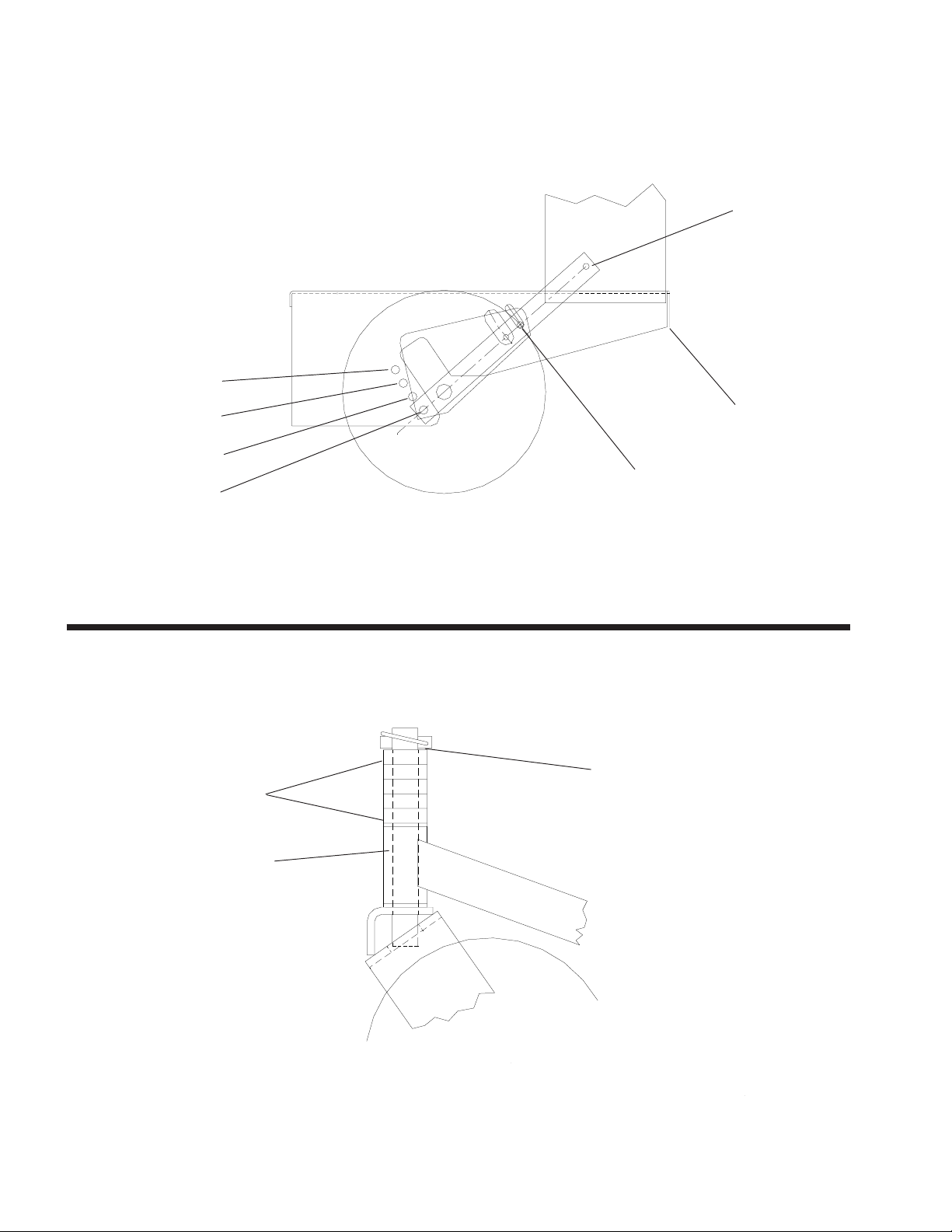
AXLE ADJUSTMENT BOLTS
POSITION
A
POSITION
B
POSITION
C
POSITION
D
REAR AXLE HEIGHT ADJUSTMENTREAR AXLE HEIGHT ADJUSTMENT
REAR AXLE HEIGHT ADJUSTMENT
REAR AXLE HEIGHT ADJUSTMENTREAR AXLE HEIGHT ADJUSTMENT
LOOSEN BOLTS EACH SIDE
Figure 1
AXLE PIVOT BOLTS
PLACE JACK HERE
1/2" SPACERS
CASTER
SWIVEL
CASTER HEIGHT ADJUSTMENTCASTER HEIGHT ADJUSTMENT
CASTER HEIGHT ADJUSTMENT
CASTER HEIGHT ADJUSTMENTCASTER HEIGHT ADJUSTMENT
Figure 2
MACHINERY BUSHING
4

BLADE DRIVE BELT ADJUSTMENTSBLADE DRIVE BELT ADJUSTMENTS
BLADE DRIVE BELT ADJUSTMENTS
BLADE DRIVE BELT ADJUSTMENTSBLADE DRIVE BELT ADJUSTMENTS
WARNINGWARNING
WARNING
WARNINGWARNING
BEFORE PERFORMING ADJUSTMENTS ONBEFORE PERFORMING ADJUSTMENTS ON
BEFORE PERFORMING ADJUSTMENTS ON
BEFORE PERFORMING ADJUSTMENTS ONBEFORE PERFORMING ADJUSTMENTS ON
BLADE BELT, TURN MOWER OFF, CLOSE FUELBLADE BELT, TURN MOWER OFF, CLOSE FUEL
BLADE BELT, TURN MOWER OFF, CLOSE FUEL
BLADE BELT, TURN MOWER OFF, CLOSE FUELBLADE BELT, TURN MOWER OFF, CLOSE FUEL
VALVE, AND DISCONNECT SPARK PLUG WIRE.VALVE, AND DISCONNECT SPARK PLUG WIRE.
VALVE, AND DISCONNECT SPARK PLUG WIRE.
VALVE, AND DISCONNECT SPARK PLUG WIRE.VALVE, AND DISCONNECT SPARK PLUG WIRE.
1. Remove front deck belt shield.
2. Loosen whiz nut on turnbuckle.
3. Set belt tension when engagement lever is in the
engaged position.
4. To increase belt tension rotate turnbuckle toward the
rear of the mower until desired tension is gained. Do not
over tighten belts, to much tension will reduce belt and
spindle bearing life. See figure # 6
5. Tighten whiz nut on turnbuckle and install belt shield.
AUXILIARY BLADE DRIVE BELTAUXILIARY BLADE DRIVE BELT
AUXILIARY BLADE DRIVE BELT
AUXILIARY BLADE DRIVE BELTAUXILIARY BLADE DRIVE BELT
(48" MODELS ONLY)(48" MODELS ONLY)
(48" MODELS ONLY)
(48" MODELS ONLY)(48" MODELS ONLY)
To adjust tension of the auxiliary belt rotate nut on
linkage that is attached to deck strap located on the right
side of cutter deck.
AUXILARY BELT ADJUSTMENT
ROD
IDLER PIVOT POINT
TURNBUCKLE
4
1/4"
5
ENGAGEMENT IDLER
ASSEMBLY
Figure 6
5
SETUP AND ADJUSTMENTS FORSETUP AND ADJUSTMENTS FOR
SETUP AND ADJUSTMENTS FOR
SETUP AND ADJUSTMENTS FORSETUP AND ADJUSTMENTS FOR
HUSQVARNA 32", 36" AND 48" COMMERCIAL MOWERSHUSQVARNA 32", 36" AND 48" COMMERCIAL MOWERS
HUSQVARNA 32", 36" AND 48" COMMERCIAL MOWERS
HUSQVARNA 32", 36" AND 48" COMMERCIAL MOWERSHUSQVARNA 32", 36" AND 48" COMMERCIAL MOWERS
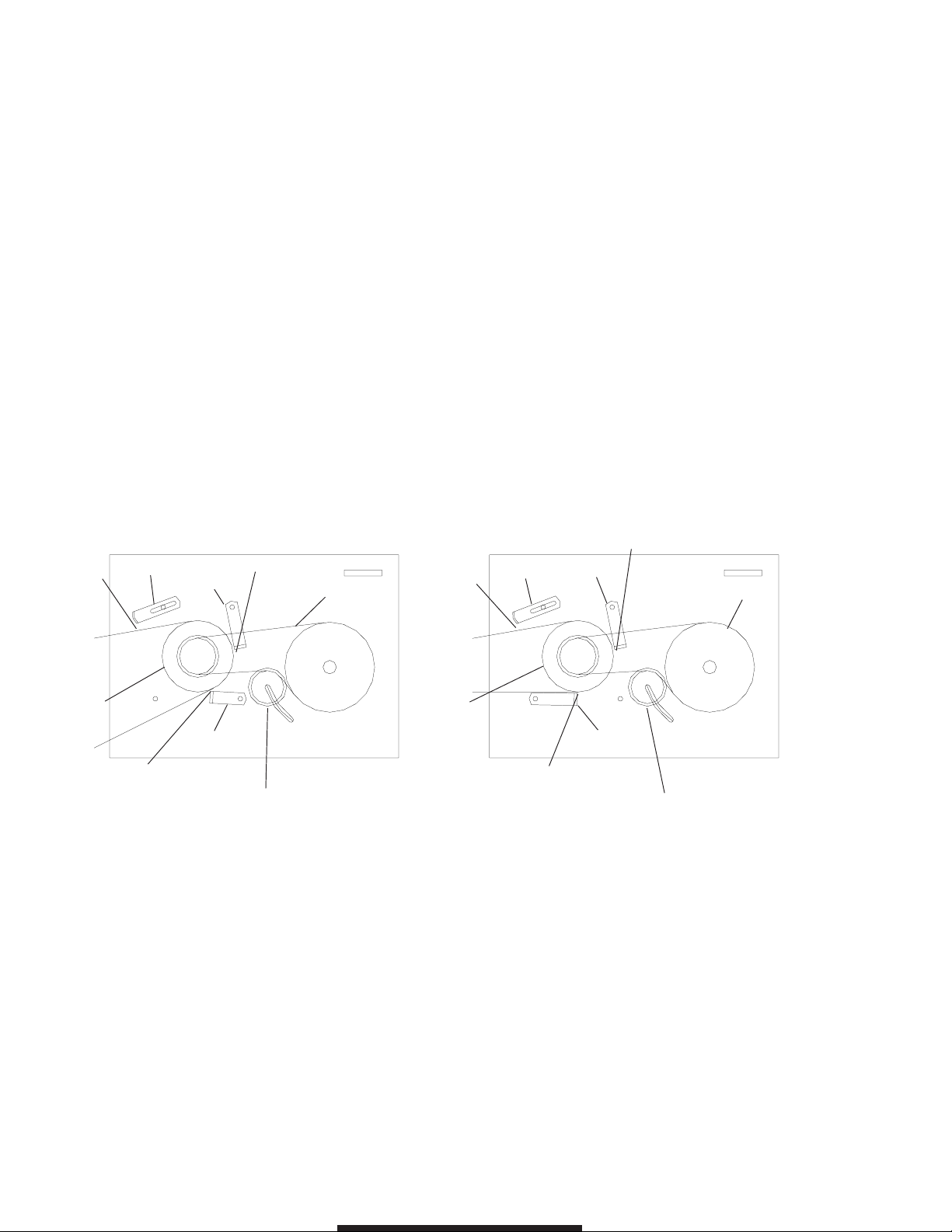
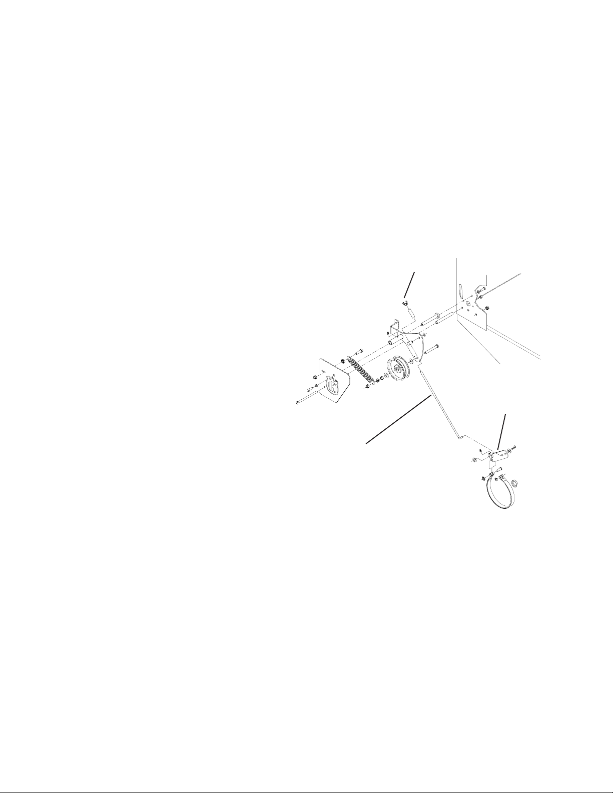
TRANSMISSION DRIVE BELTTRANSMISSION DRIVE BELT
TRANSMISSION DRIVE BELT
TRANSMISSION DRIVE BELTTRANSMISSION DRIVE BELT
To increase the tension of the transmission belt, loosen
the nut on the underside of the transmission idler pulley
located under the rear deck, slide the idler assembly
inward to increase tension and tighten the nut to secure.
See figures 4 & 5.
BELT GUIDESBELT GUIDES
BELT GUIDES
BELT GUIDESBELT GUIDES
Belt guides under rear deck are adjusted as shown in
figures 4 and 5
NOTE: The blades should come to a stop fromNOTE: The blades should come to a stop from
NOTE: The blades should come to a stop from
NOTE: The blades should come to a stop fromNOTE: The blades should come to a stop from
maximum speed within 7 seconds aftermaximum speed within 7 seconds after
maximum speed within 7 seconds after
maximum speed within 7 seconds aftermaximum speed within 7 seconds after
disengaging.disengaging.
disengaging.
disengaging.disengaging.
BLADE ENGAGEMENT LEVERBLADE ENGAGEMENT LEVER
BLADE ENGAGEMENT LEVER
BLADE ENGAGEMENT LEVERBLADE ENGAGEMENT LEVER
The blade engagement lever needs to be adjusted so
the lever does not come in contact with control panel
when the lever is in the off position.
To adjust, remove the clevis pin from the yoke and
adjust by turning the yoke. The clevis pin connects the
blade engagement lever to the yoke, and the yoke is
connected to the blade engagement rod that runs to the
bellcrank on the rear deck.
102036
1/2"
ENGINE PULLEY
1/8" CLEARANCE
TRANSMISSION IDLER PULLEY
32" & 36" MODEL32" & 36" MODEL
32" & 36" MODEL
32" & 36" MODEL32" & 36" MODEL
1/8" CLEARANCE
103462
103463
Figure 4
TRANSMISSION BELT
102036
1/2"
ENGINE PULLEY
1/8" CLEARANCE
48" MODEL48" MODEL
48" MODEL
48" MODEL48" MODEL
1/4" CLEARANCE
103462
TRANSMISSION BELT
103462
TRANSMISSION IDLER PULLEY
Figure 5
6

SETUP AND ADJUSTMENTS FORSETUP AND ADJUSTMENTS FOR
SETUP AND ADJUSTMENTS FOR
SETUP AND ADJUSTMENTS FORSETUP AND ADJUSTMENTS FOR
HUSQVARNA 32", 36" AND 48" COMMERCIAL MOWERSHUSQVARNA 32", 36" AND 48" COMMERCIAL MOWERS
HUSQVARNA 32", 36" AND 48" COMMERCIAL MOWERS
HUSQVARNA 32", 36" AND 48" COMMERCIAL MOWERSHUSQVARNA 32", 36" AND 48" COMMERCIAL MOWERS
CUTTING HEIGHT ADJUSTMENT CHARTCUTTING HEIGHT ADJUSTMENT CHART
CUTTING HEIGHT ADJUSTMENT CHART
CUTTING HEIGHT ADJUSTMENT CHARTCUTTING HEIGHT ADJUSTMENT CHART
AXLE
POSITION
A
B
C
D
NUMBER OF
SPACERS BELOW
CASTER ARM
0
1
2
3
3
4
4
5
NUMBER OF 1/4" BLADE SPACERS
UNDER CUTTER HOUSING
4
3
2
1
0
4
3
2
1
0
4
3
2
1
0
4
3
2
1
0
4
3
2
1
0
4
3
2
1
0
4
3
2
1
0
4
3
2
1
0
CUTTING HEIGHT
(IN INCHES)
1 1/2
1 3/4
2
2 1/4
2 1/2
1 3/4
2
2 1/4
2 1/2
2 3/4
2 1/2
2 3/4
3
3 1/4
3 1/2
3
3 1/4
3 1/2
3 3/4
4
3 1/4
3 1/2
3 3/4
4
4 1/4
3 1/2
3 3/4
4
4 1/4
4 1/2
3 3/4
4
4 1/4
4 1/2
4 3/4
4
4 1/4
4 1/2
4 3/4
5
1. To quickly achieve small changes in cutting heights,
move the spacers from under the cutter housing to
above the cutter pulley. (Each spacer moved will give an
additional 1/4" of cutting height ).
USE ONLY 4 BLADE SPACERS MAXIMUM
7
ETS Gear Drive Intermediate Walk Behind
Models:
968999117 / W3613ETS
968999120 / W4815ETS
8

Setup & Adjustments
MAINTENANCE
1. Keep all nuts, bolts, and screws tight to
keep mower in safe operating condition.
2. Never store the mower with gas in the tank
inside a building where fumes can reach an
open flame or spark. Allow engine to cool
before storing in an enclosure.
3. To reduce fire hazard, keep mower free of
grass, leaves, or excessive grease.
4. Check grass catcher assembly frequently
for wear or deterioration. Replace bag if
loose seams or tears are evident.
5. Have your mower inspected and serviced
each year by an authorized HUSQVARNA
dealer. Determine if any additional devices
are available which might upgrade the safety
of your mower .
6. Use only authentic HUSQVARNA re-
placement parts to insure the safety and
quality of your mower is maintained.
7. Safety decals should be replaced if they
are missing or illegible. Decals may be
purchased from your HUSQVARNA dealer.
FRONT CASTER WHEELS
1. Mount front caster wheel assemblies.
Installation includes fastening casters to front
of the cutter deck using 3/8 x 1" hex head
capscrews.
FUEL TANK
1. Place fuel tank on tank support, making sure
to get the studs through the slots on the top of
the tank support. Place the 5/16” flat washer ,
spring, the other 5/16 flat washer and the 5/16”
nut on the stud. Snug 5/16” nut, but do not over
tighten.
HANDLE ASSEMBLY
1. Align the upper mounting holes in handle
with the upper hole in the tank support.
2. Install two 3/8" x 1" screws through
matched holes and loosely install 3/8" nuts.
3. Align the lower holes and inst all hardware
as above, tighten upper and lower hardware.
LINKAGE INSTALLATION
1. Install drive linkage into the hole in the idler
arm on the inside of the tank support. The drive
linkages are fastened to the drive levers on the
handle assembly . Secure the drive linkages to
the idler arm by inserting a retaining ring
through the small hole in the end of the drive
linkage.
2. Install shifter to transmission with 1/4" x 1"
screws.
The shifter is located in the inner box and
hardware is pre-assembled into the bracket
on the transmission.
3. Install blade control rod into the bellcrank
on the left side of the tank support. Secure
rod with ring type retainer .
4. Refer to the section of this manual on
adjustments for the proper adjustment of the
linkages you are installing. The linkages were
set at the factory but must be checked before
operating mower to insure of the proper
setting. Always check 100% of the adjustments before you operate the mower.
5. Connect the two halves of the wiring harness together. The four prong connectors
have a locking tab that shows which way to
line them up and guarantees that they are
connected properly when the lock snaps.
6. Install the chute deflector to the side of the
mower deck. Bolt it into place using the two
5/16" x 1" screws and nuts pre-assembled
into the mounting tabs on the deck. T ighten
the screws very securely with the chute
completely covering the discharge opening
and tight against the side of deck.
THROTTLE INSTALLATION
1. Connect the throttle cable end to the
throttle mechanism on engine, leaving the
cable clamp loose. Push throttle lever on
console completely forward. Then pull the
cable through the clamp on engine and
tighten the cable clamp. Move the throttle
lever back and forth to ensure proper installation.
9
Setup & Adjustments
GAS LINE INSTALLATION
1. The gas line is factory installed on the engine.
Attach loose end to fuel tank hose barb and
secure with hose clamp.
POSITIONING FRONT CASTER SPACERS
1. Using the cutting height chart, find the correct
number of spacers to be placed under the
caster swivel.
2. Remove the lynch pin and washer from the
top of caster and reposition spacers to the
desired cutting height from the chart. See figure
# 2
AXLE HEIGHT ADJUSTMENT
1. To adjust rear axle, stop engine and place
drive levers in the neutral lock position, remove
spark plug wire.
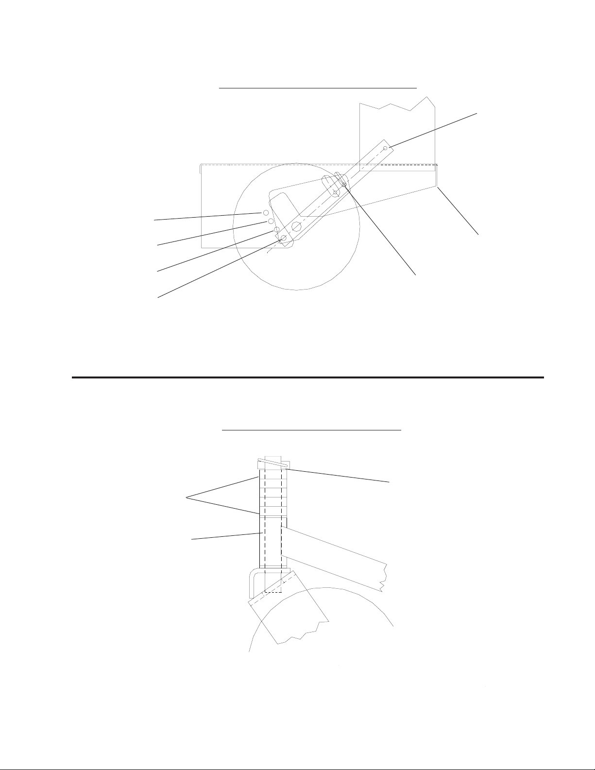
BRAKE ROD ADJUSTMENT
1. Make sure the rod is installed into the proper
hole in the brake arm. The brake rod should be
in bottom hole on the brake arm as shown
below. Never use the upper hole. The proper
adjustment can not be achived in this position.
2. To increase braking. Turn the wing nut down
on the brake rod. Do not turn the wingnut down
to far as this will result a constant braking action
and will excessively wear the brake band and
cause premature failure.
Wingnut
2. Remove lower belt shield from underside of
rear deck for better access to axle adjustment
bolts.
3. Loosen axle pivot bolts and axle adjustment
bolts.
See figure # 1.
4. Place a jack under center of rear deck raise
the jack slightly so axle adjustment bolts may be
removed.
5. With the jack raise or lower the rear deck to
the desired position using the chart to ensure
proper height. Reinstall the axle adjustment
bolts and tighten.
A tapered punch may be used to help align the
holes. See figure #1.
NOTE:
It may be necessary to readjust drive and brake
linkages.
Brake arm
Brake Rod
NOTE:
To achieve the best quality cut, the blades
should be level with the ground or slightly tipped
forward
10
AXLE ADJUSTMENT
BOLTS
POSITION A
Setup & Adjustments
REAR AXLE HEIGHT ADJUSTMENT
POSITION B
POSITION
C
POSITION
D
1/2" SPACERS
PLACE JACK
HERE
LOOSEN BOL TS EACH
SIDE
Figure 1
CASTER HEIGHT ADJUSTMENT
MACHINERY BUSHING
CASTER SWIVEL
Figure 2
11
 Loading...