


Oper
ator’s manual Manuel d’utilisation
Manual de instrucciones
560BTS 570BTS 580BTS
560BFS 570BFS 580BFS
Please r
ead the operator’s manual carefully and make sure you understand the instructions before using the machine.
Lire attentivement et bien assimiler le manuel d’utilisation avant d’utiliser la machine.
Lea detenidamente el manual de instrucciones y asegúrese de entender su contenido antes de utilizar la máquina.
UUUUSSSS ((((2222----22227777))
CCCCAAAA ((((22228888----55553333))
UUUUEEEE ((((55554444---- 77779999))
))
))
))
Symbols
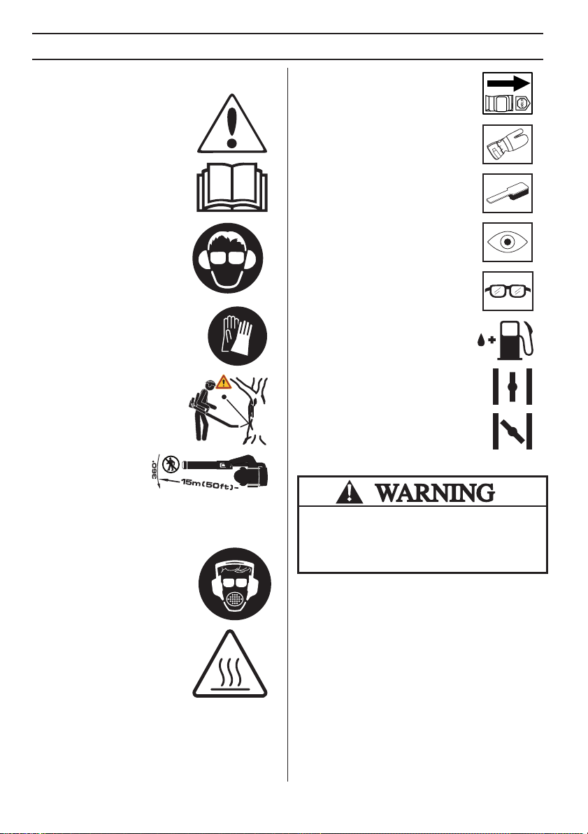
W
ARNING! The machine can be a
dangerous tool if used incorrectly or
carelessly, which can cause serious
or fatal injury to the operator or
others.
Please read the operator’s manual
carefully and make sure you
understand the instructions before
using the machine.
KEY TO SYMBOLS
Switch off the engine b
switch to the STOP position before
carrying out any checks or
maintenance.
Always wear protective gloves.
Regular cleaning is required.
y moving the stop
Always wear:
• Hearing protection
• Approved eye protection
Gloves should be worn when
necessary.
The blower can forcibly throw
objects that can bounce back.
This can result in serious eye
injuries if the recommended
safety equipment is not used.
The blower operator
must make sure that no
bystanders or animals
come nearer than 15
metres. Whenever
several operators are working in the same work area, they
should maintain a safe distance of at least 15 metres from
one another.
A breathing mask should be used
when there is a risk of dust.
Visual check.
Protective goggles or a visor must be
worn.
Refuelling.
Choke lever in ”open position”.
Choke lever in ”closed position”.
The engine exhaust from this product
contains chemicals known to the State
of California to cause cancer, birth
defects or other reproductive harm.
Keep all parts of your body away
from hot surfaces.
Other symbols/decals on the
machine refer to special certification requirements
for certain markets.
2
–
English
1155849-49
Rev.
2
2013-03-22
CONTENTS
!
!
!
Contents
KEY
TO SYMBOLS
Symbols
................................................................ 2
CONTENTS
Contents
Note the following before starting: ........................ 3
INTR
Dear customer!
WHA
What is what on the b
What is what on the blower? ................................ 6
What is what on the blower? ................................ 7
GENERAL SAFETY PRECA
Gener
SAFETY INSTR
P
Machine′s safety equipment ................................. 10
Checking, maintaining and servicing the
machine
General working instructions ................................ 12
ASSEMBL
Assemb
FUEL HANDLING
Fuel
Fueling .................................................................. 17
ST
Star
MAINTENANCE
Gener
Carburetor ............................................................ 20
Muffler .................................................................. 20
Cooling system ..................................................... 20
Air intake screen ................................................... 21
Spark plug ............................................................ 21
Air filter ................................................................. 21
Shoulder strap ...................................................... 22
Maintenance schedule ......................................... 23
TECHNICAL D
T
FEDERAL AND CALIFORNIA EMISSIONS
CONTROL WARRANTY STATEMENT
Y
............................................................... 3
ODUCTION
..................................................... 4
T IS WHAT?
lower? ................................ 5
UTIONS
al ................................................................. 8
UCTIONS
ersonal protective equipment ............................. 10
′
s safety equipment ................................. 11
Y
ling the blow pipe and control handle ...... 15
...................................................................... 16
ARTING AND STOPPING
ting and stopping ........................................... 18
al ................................................................. 20
ATA
echnical data ...................................................... 24
OUR WARRANTY RIGHTS AND OBLIGATIONS 26
Note the f
ollowing before
starting:
Please read the oper
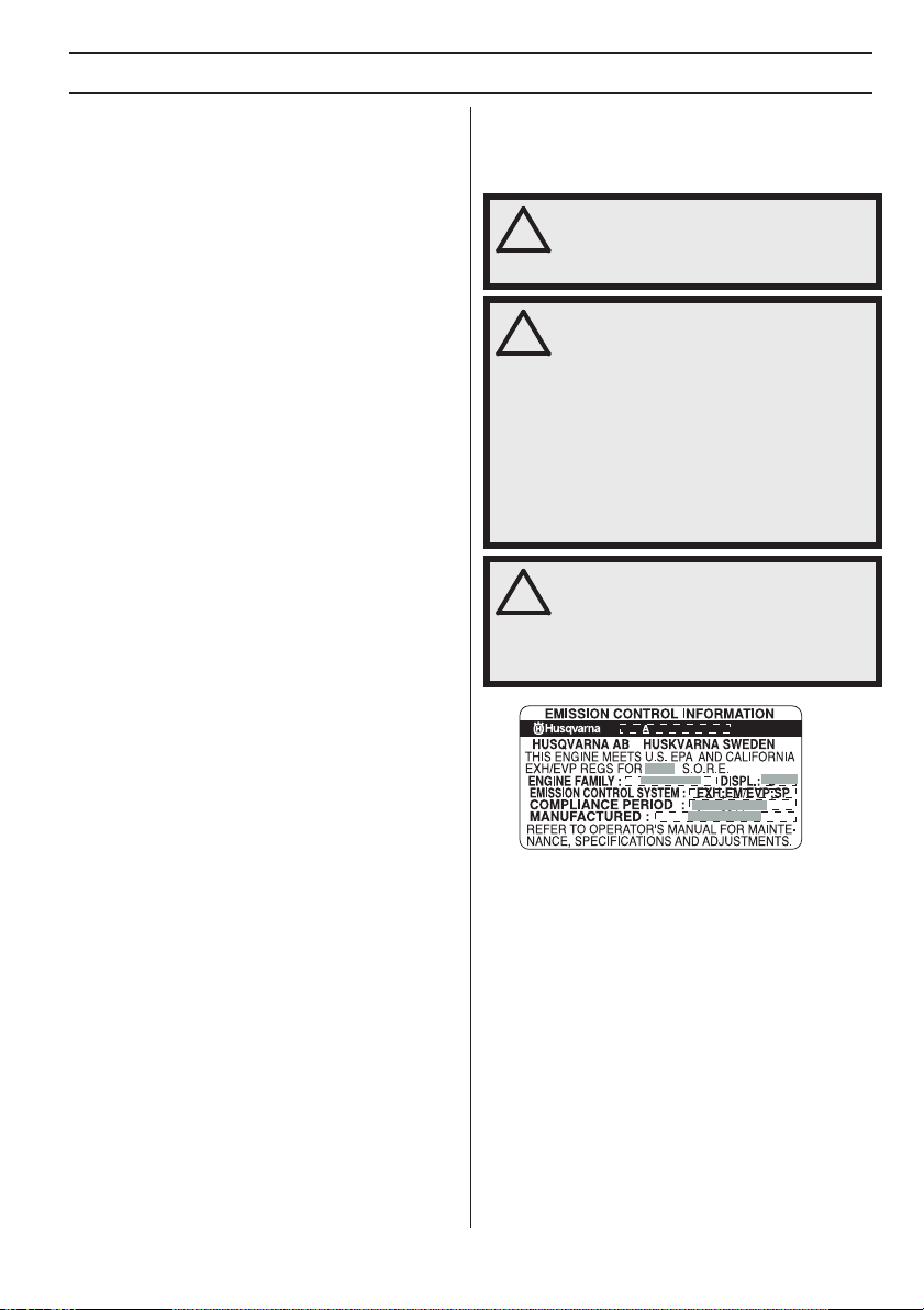
This decal certifies that the product has been approved in
accordance with American exhaust emissions
requirements EPA Ph III and CARB Tier III. The
Emissions Compliance Period referred to on the
Emissions Compliance label indicates the numbers of
operating hours for which the engine has been shown to
meet Federal and California emission requirements.
Husqvarna AB has a policy of continuous product
development and therefore reserves the right to modify
the design and appearance of products without prior
notice.
The machine is only designed for blowing lawns,
pathways, asphalt roads and the like.
For customer assistance, contact us at our website:
www.usa.husqvarna.com
ator’s manual carefully.
W
ARNING! Long-term exposure to noise
can result in permanent hearing
impairment. So always use approved
hearing protection.
W
ARNING! Under no circumstances may
the design of the machine be modified
without the permission of the
manufacturer. Always use genuine
accessories. Non-authorized
modifications and/or accessories can
result in serious personal injury or the
death of the operator or others.
Your warranty may not cover damage or
liability caused by the use of nonauthorized accessories or replacement
parts.
W
ARNING! A blower is a dangerous tool
if used carelessly or incorrectly and can
cause serious, even fatal injuries. It is
extremely important that you read and
understand the contents of this
Operator’s manual.
Jan. 2011
1155849-49
Rev.
2
2013-03-22
English –
3

INTR
ODUCTION
Dear customer!
Cong
ratulations on your choice to buy a Husqvarna product! Husqvarna is based on a tradition that dates back to 1689,
when the Swedish King Karl XI ordered the construction of a factory on the banks of the Huskvarna River, for production
of muskets. The location was logical, since water power was harnessed from the Huskvarna River to create the waterpowered plant. During over 300 years of continuous operation, the Husqvarna factory has produced a lot of different
products, from wood stoves to modern kitchen appliances, sewing machines, bicycles, motorcycles etc. In 1956, the first
motor driven lawn mowers appeared, followed by chain saws in 1959, and it is within this area Husqvarna is working
today.
Today Husqvarna is one of the leading manufacturers in the world of forest and garden products, with quality as our
highest priority. We develop, manufacture and market high quality motor driven products for forestry and gardening as
well as for building and construction industry.
Your purchase gives you access to professional help with repairs and service whenever this may be necessary. If the
retailer who sells your machine is not one of our authorized dealers, ask for the address of your nearest servicing dealer.
It is our wish that you will be satisfied with your product and that it will be your companion for a long time. Think of this
operator
′
s manual as a valuable document. By following its′ content (using, service, maintenance etc) the life span and
the second-hand value of the machine can be extended. If you ever lend or sell this machine, make sure that the
borrower or buyer gets the operator
Thank you for using a Husqvarna product.
Husqvarna AB has a policy of continuous product development and therefore reserves the right to modify the design and
appearance of products without prior notice.
For customer assistance, contact us at our website: www.usa.husqvarna.com
′
s manual, so they will also know how to properly maintain and use it.
4
–
English
1155849-49
Rev.
2
2013-03-22
8
9
25
26
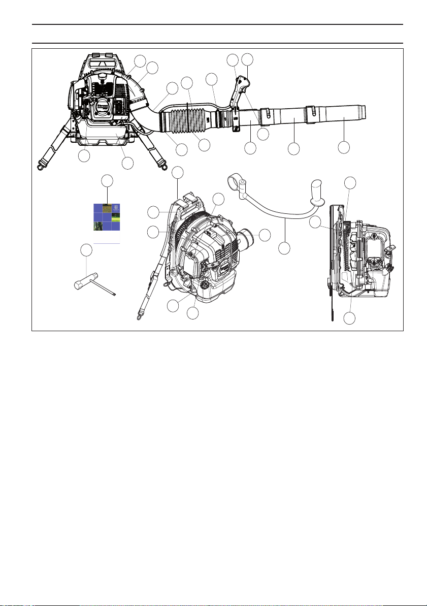
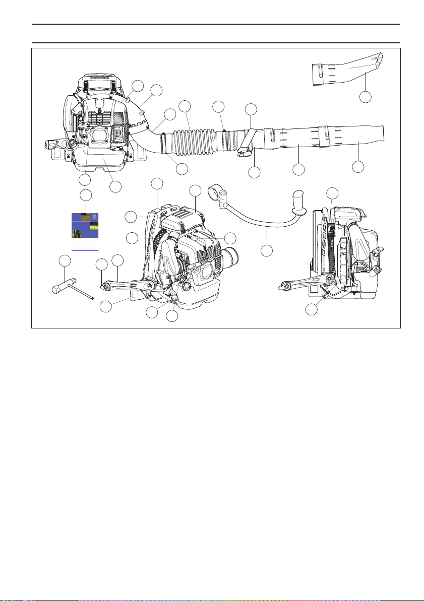
What is what on the b
1
Frame
2 Harness
3 Engine cover
4 Fan shell
5 Air intake screen
6Fan
7 Air filter
8 Starter handle
9 Fuel tank
10 Pad
11 Spark plug
12 Vibration damping system
13 Choke control
14 Control handle/Operating handle
lower? 560BTS, 560BFS
WHA
T IS
WHA
T?
14
3
4
20
18
15
19
16
19
22
21
23
24
2
12
7
1
10
5
11
17
12
13
15 Throttle setting lever. Stop switch positioned behind
lever. (BFS)
16 Stop switch with throttle position setting (BTS),
17 Throttle trigger (BTS)
18 Handlebar (Accessory)
19 Elbow
20 Clamp
21 Flexible hose
22 Control pipe
23 Clamp
24 Intermediate pipe
25 Blow pipe
26 Operator’s manual
27 Combination spanner
28 Control handle/operating handle (BFS)
6
1155849-49
Rev.
2
2013-03-22
English
–
5
WHA
T IS
WHA
T?
3
4
20
18
19
14
15
25
8
26
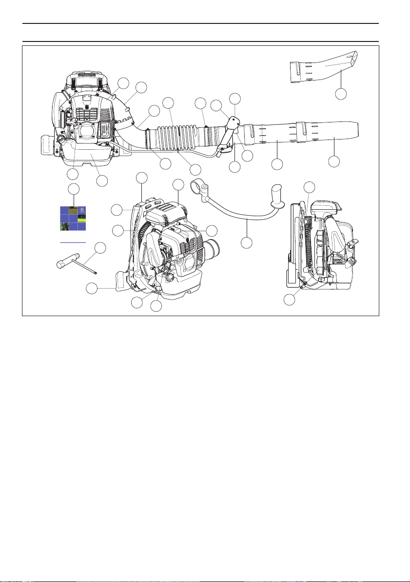
What is what on the b
1
Frame
2 Harness
3 Engine cover
4 Fan shell
5 Air intake screen
6Fan
7 Air filter
8 Starter handle
9 Fuel tank
10 Pad
11 Spark plug
12 Vibration damping system
13 Choke control
14 Control handle/Operating handle
9
1
5
27
10
lower? 570BTS, 580BTS
19
2
12
13
22
7
11
15 Stop switch with throttle position setting
16 Throttle trigger
17 Handlebar (Accessory)
18 Elbow
19 Clamp
20 Flexible hose
21 Control pipe
22 Clamp
23 Intermediate pipe
24 Blow pipe
25 Flat nozzle (Accessory)
26 Operator’s manual
27 Combination spanner
16
21
17
23
6
24
12
6
–
English
1155849-49
Rev.
2
2013-03-22
WHA
T IS
WHA
T?
3
4
20
18
19
14
25
8
26
27
What is what on the b
1
Frame
2 Harness
3 Engine cover
4 Fan shell
5 Air intake screen
6Fan
7 Air filter
8 Starter handle
9 Fuel tank
10 Pad
11 Spark plug
12 Vibration damping system
13 Choke control
14 Control handle/Operating handle
9
1
5
16
15
10
lower? 570BFS, 580BFS
19
2
12
7
13
21
11
17
15 Stop switch with throttle position setting
16 Throttle trigger
17 Handlebar (Accessory)
18 Elbow
19 Clamp
20 Flexible hose
21 Control pipe
22 Clamp
23 Intermediate pipe
24 Blow pipe
25 Flat nozzle (Accessory)
26 Operator’s manual
27 Combination spanner
23
6
24
12
1155849-49
Rev.
2
2013-03-22
English
–
7
GENERAL SAFETY PRECA
General
IMPORTANT!
The machine is only designed for blowing lawns,
pathways, asphalt roads and the like.
Do an overall inspection of the machine before use, see
maintenance schedule.
Never use the machine if you are tired, if you have drunk
alcohol, or if you are taking medication that could affect
your vision, your judgement or your co-ordination.
Wear personal protective equipment. See instructions
under the heading ”Personal protective equipment”.
Never use a machine that has been modified in any way
from its original specification.
Never use a machine that is faulty. Carry out the checks,
maintenance and service instructions described in this
manual. Some maintenance and service measures
must be carried out by trained and qualified specialists.
See instructions under the heading Maintenance.
All covers and guards must be fitted before starting.
Ensure that the spark plug cap and ignition lead are
undamaged to avoid the risk of electric shock.
The blower operator must make sure that no bystanders
or animals come nearer than 15 metres. Whenever
several operators are working in the same work area,
they should maintain a safe distance of at least 15
metres from one another.
Never allow children to use the machine.
Never allow anyone else to use the machine without first
ensuring that they have understood the contents of the
operator’s manual.
Always check for any objects that may block the air
intake screen before beginning work.
Never remove the air intake screen.
In case of emergency, release yourself from the
machine by opening the waist and chest belt and let the
machine fall backwards.
Always contact local authorities and make sure you are
following applicable directives.
Keep all parts of your body away from hot surfaces.
UTIONS
Star
ting
•
Never start the machine indoors. Exhaust fumes can
be dangerous if inhaled.
• Observe the surroundings and ensure that no people
or animals can come into contact with the blower.
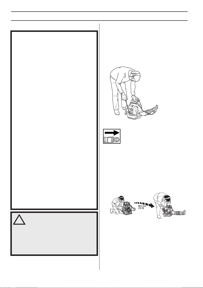
• Place the machine on the ground, press the machine
body against the ground with your left hand (NOTE!
Not your foot). Now grasp the starter handle with your
right hand and then pull quickly and firmly.
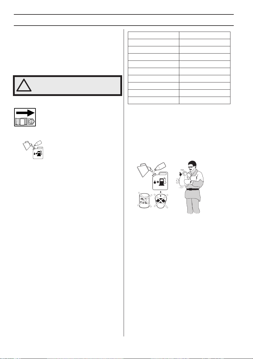
Fuel saf
•
• Never refuel the machine while the engine is running.
• Make sure there is plenty of ventilation when refuelling
• Avoid all skin contact with fuel. Fuel is a skin irritant
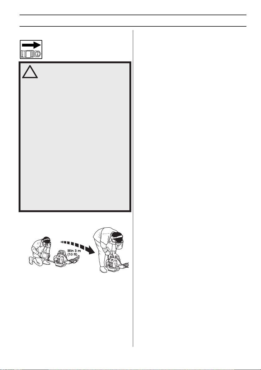
• Move the machine at least 10 ft (3 m) from the
ety
Always use a fuel container with an anti-spill valve.
Always stop the engine and let it cool for a few minutes
before refuelling.
or mixing fuel (gasoline and 2-stroke oil).
and may even cause skin changes.
refuelling point before starting it.
8
–
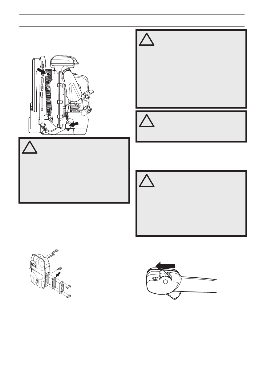
W
ARNING! This machine produces an
electromagnetic field during operation.
!
This field may under some
circumstances interfere with active or
passive medical implants. To reduce the
risk of serious or fatal injury, we
recommend persons with medical
implants to consult their physician and
the medical implant manufacturer before
operating this machine.
English
• Never start the machine:
- If you have spilled fuel on it. Wipe off the spillage and
allow remaining fuel to evaporate.
- If you have spilled fuel on yourself or your clothes,
change your clothes. Wash any part of your body that has
come in contact with fuel. Use soap and water.
- If the machine is leaking fuel. Check regularly for leaks
from the fuel cap and fuel lines.
1155849-49
Rev.
2
2013-03-22
GENERAL SAFETY PRECA
T
ransport and storage
•
Store and transport the machine and fuel so that there
is no risk of any leakage or fumes coming into contact
with sparks or naked flames, for example, from
electrical machinery, electric motors, electrical relays/
switches or boilers.
• When storing and transporting fuel always use
approved containers intended for this purpose.
• When storing the machine for long periods the fuel
tank must be emptied. Contact your local gas station
to find out where to dispose of excess fuel. Empty the
fuel tank and press the primer until all fuel has been
emptied. Remove the spark plug and drop a spoon of
2-stroke oil in the cylinder. Turn over the engine a few
times and then put the spark plug back in place.
• Ensure the machine is cleaned and that a complete
service is carried out before long-term storage.
• Secure the machine during transport.
• Store the machine in a dry, cool, well-aired and dustfree location. Store the machine out of reach of
children.
WARNING! Take care when handling fuel.
Bear in mind the risk of fire, explosion
!
and inhaling fumes.
UTIONS
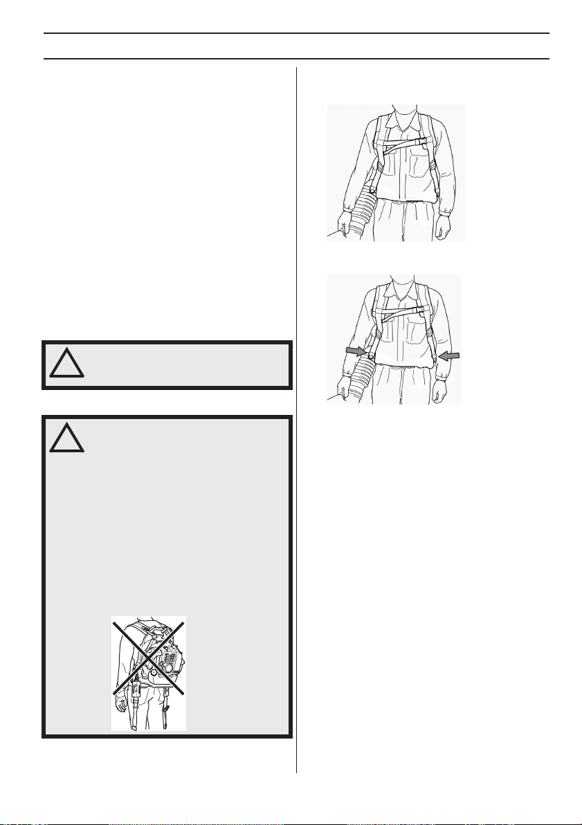
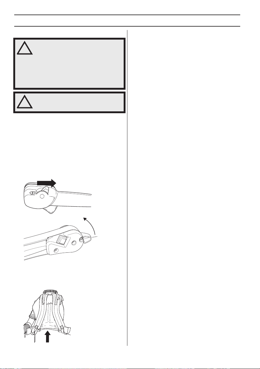
A correctly adjusted harness and machine significantly
facilitates the work. Adjust the harness to give the best
working position.
Tighten the side straps so that the pressure is evenly
distributed across the shoulders.
Adjusting the harness
WARNING! The harness must always be
worn when working with the machine.
!
Failure to do so means you will be unable
to manoeuvre safely and this can result
in injury to yourself or others.
Make sure that the waist belt is closed
and correctly adjusted.
If you not using a waist belt, be sure to
remove it from the unit and store it. There
is a risk that the belt will be caught,
toppling the unit.
There is a risk that an unclosed belt can
get stuck or sucked into the fan of the
machine.
1155849-49
Rev.
2
2013-03-22
Tighten and adjust the breast belt for the best working
position.
NOTE!
560BTS, BFS has no chest belt or waist belt.
English –
9
SAFETY INSTRUCTIONS
!
Personal protective equipment
WARNING! You must use approved
personal protective equipment whenever
!
you use the machine. Personal protective
equipment cannot eliminate the risk of
injury but it will reduce the degree of
injury if an accident does happen. Ask
your dealer for help in choosing the right
equipment. Please read the operator’s
manual carefully and make sure you
understand the instructions before using
the machine.
WARNING! Listen out for warning signals
or shouts when you are wearing hearing
!
protection. Always remove your hearing
protection as soon as the engine stops.
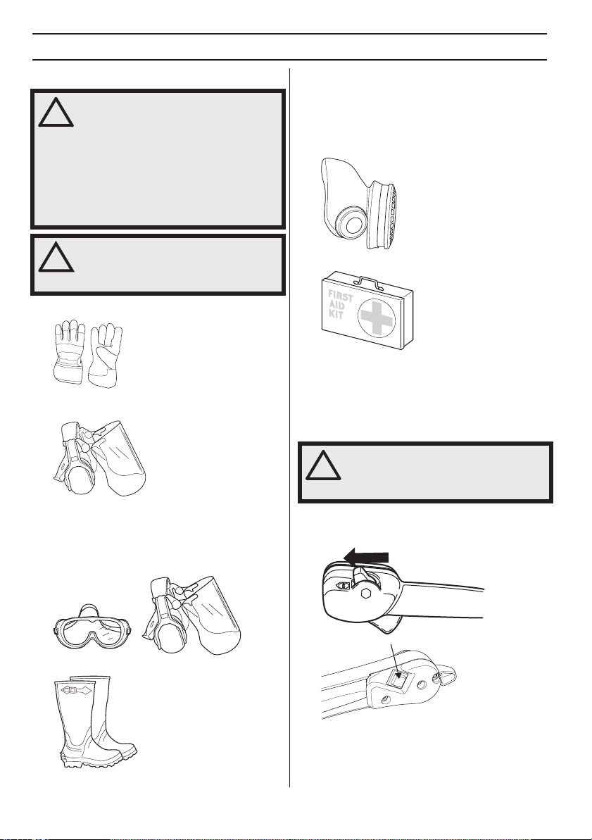
• Gloves should be worn when necessary.
• Wear hearing protection that provides adequate noise
reduction.
• Always wear approved eye protection. If you use a
visor then you must also wear approved protective
goggles. Approved protective goggles must comply
with standard ANSI Z87.1 in the USA or EN 166 in EU
countries. Blows from branches or objects that are
thrown can damage the eyes.
• Wear clothes made of a strong fabric and avoid loose
clothing that can catch on twigs and branches. Always
wear heavy, long pants. Do not wear jewellery, shorts
sandals or go barefoot. Secure hair so it is above
shoulder level.
• A breathing mask should be used when there is a risk
of dust.
• Always have a first aid kit nearby.
Machine′s safety equipment
This section describes the machine′s safety equipment,
its purpose, and how checks and maintenance should be
carried out to ensure that it operates correctly. See the
”What is what?” section to locate where this equipment is
positioned on your machine.
WARNING! Never use a machine that has
faulty safety equipment! Carry out the
inspection, maintenance and service
routines listed in this section.
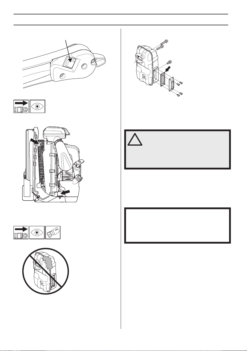
Stop switch
Use the stop switch to switch off the engine.
• Wear sturdy, non-slip boots.
10 – English
Remove the ignition cable and the spark plug to carry out
inspection and maintenance.
1155849-49 Rev. 2 2013-03-22
SAFETY INSTRUCTIONS
!
!
!
Vibration damping system
Your machine is equipped with a vibration damping
system that is designed to reduce vibration and make
operation easier.
x2
WARNING! Overexposure to vibration
can lead to circulatory damage or nerve
!
damage in people who have impaired
circulation. Contact your doctor if you
experience symptoms of overexposure
to vibration. Such symptoms include
numbness, loss of feeling, tingling,
pricking, pain, loss of strength, changes
in skin colour or condition. These
symptoms normally appear in the
fingers, hands or wrists. The risk
increases at low temperatures.
Muffler
The muffler is designed to keep noise levels to a minimum
and to direct exhaust fumes away from the user.
In countries that have a warm and dry climate there is a
significant risk of fire. Consequently, we have equipped
the muffler with a spark arrestor screen mounted inside
the muffler.
WARNING!
Bear in mind that: Engine exhaust fumes
contain carbon monoxide, which can
cause carbon monoxide poisoning. For
this reason you should not start or run
the machine indoors, or anywhere that is
poorly ventilated.
The exhaust fumes from the engine are
hot and may contain sparks which can
start a fire. Never start the machine
indoors or near combustible material!
WARNING! The inside of the muffler
contain chemicals that may be
carcinogenic. Avoid contact with these
elements in the event of a damaged
muffler.
Checking, maintaining and
servicing the machine
′s safety
equipment
WARNING! All servicing and repair work
on the machine requires special training.
This is especially true of the machine
safety equipment. If your machine fails
any of the checks described below you
must contact your service agent. When
you buy any of our products we
guarantee the availability of professional
repairs and service. If the retailer who
sells your machine is not a servicing
dealer, ask him for the address of your
nearest service agent.
Stop switch
• Start the engine and make sure the engine stops
when you move the stop switch to the stop setting.
′s
For mufflers it is very important that you follow the
instructions on checking, maintaining and servicing your
machine. See instructions under the heading Checking,
maintaining and servicing the machine’s safety
equipment.
1155849-49 Rev. 2 2013-03-22
English – 11
SAFETY INSTRUCTIONS
!
The engine is stopped by switching the ignition off using
the stop switch.
Vibration damping system
• Check the vibration damping units regularly for cracks
or deformation. Replace them if damaged.
x2
• Check that the vibration damping element is
undamaged and securely attached.
Muffler
• Never use a machine that has a faulty muffler.
• Regularly check that the muffler is securely attached
to the machine.
• The muffler on your machine is equipped with a spark
arrestor screen; this must be cleaned regularly. See
the heading Muffler in the Maintenance chapter. A
blocked screen will cause the engine to overheat and
may lead to serious damage. Never use a muffler with
a defective spark arrestor screen.
WARNING! Never use a machine with
faulty safety equipment. The machine’s
safety equipment must be checked and
maintained as described in this section.
If your machine fails any of these checks
contact your service agent to get it
repaired.
Air filter
Never use the leaf blower without an air filter or with a
damaged or deformed filter element as unfiltered, dusty
air can quickly destroy the engine.
General working instructions
IMPORTANT! This section considers basic safety rules
when working with blowers. If you encounter a situation
where you are uncertain how to proceed you should ask
an expert. Contact your dealer or your service
workshop. Avoid all usage which you consider to be
beyond your capability.
Show consideration to persons in your surroundings by
avoiding using the machine at unsuitable times, such as
late in the evening or early in the morning. To reduce
sound levels, limit the number of pieces of equipment
used at any one time. Read through and follow the simple
directions so that you disturb your surroundings as little as
possible.
• Use the blower with the lowest possible throttle. It is
seldom necessary to use full throttle, and many work
procedures can be done at half throttle. A lower
throttle means less noise and less dust, and it is also
easier to keep control over the rubbish collected
together/moved.
• Use a rake or a brush to release rubbish stuck to the
ground.
12 – English
1155849-49 Rev. 2 2013-03-22
SAFETY INSTRUCTIONS
• Hold the opening of the blower as close to the ground
as possible. Utilise the entire length of the blow pipe
to keep the air current close to the ground.
• Clean up afterwards. Make sure that you have not
blown rubbish into someone’s garden.
• Operate power equipment only at reasonable hours,
not early in the morning or late at night when people
might be disturbed. Comply with times listed in local
ordinances.
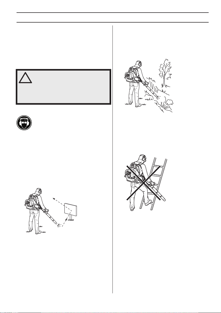
WARNING! Be aware of your
surroundings. If anyone approaches your
!
work area, set the throttle control to the
lowest throttle until the person is at a
safe distance. Direct the blower away
from people, animals, play areas, open
windows and cars etc.
Basic safety rules
• No unauthorised persons or animals may be present
in the working area, which is 15 metres.
• Allow the engine to cool before refuelling.
• Keep all parts of your body away from hot surfaces.
• If the machine catches fire or other emergency occurs
which forces you to release yourself from the
machine, open the harness straps and let the
machine fall backwards.
• The powerful currents of air can move objects at such
a speed that they can bounce back and cause serious
eye injuries.
including areas such as gutters, screens, patios, grills,
porches and gardens.
• Make sure you can move and stand safely. Check the
area around you for possible obstacles (roots, rocks,
branches, ditches, etc.) in case you have to move
suddenly. Take great care when working on sloping
ground.
• Never put the machine down with the engine running
unless you have it in clear sight.
• Engine exhaust fumes contain carbon monoxide,
which can cause carbon monoxide poisoning. For this
reason you should not start or run the machine
indoors, or anywhere that is poorly ventilated.
• The blower must not be used while on a ladder or
scaffolding.
• Do not direct the air jet towards people or animals.
• Stop the engine before assembling or dismantling
accessories or other parts.
• Do not use the machine in bad weather, such as
dense fog, heavy rain, strong wind, intense cold, etc.
Working in bad weather is tiring and can lead to
dangerous conditions, e.g. slippery surfaces.
• Minimise the blowing time by lightly wetting dusty
areas or using spray equipment.
• Conserve water by using power blowers instead of
hoses for many lawn and garden applications,
1155849-49 Rev. 2 2013-03-22
• CAUTION! Do not use the machine unless you are
able to call for help in the event of an accident.
English – 13
SAFETY INSTRUCTIONS
Basic working techniques
WARNING! Watch out for thrown objects.
Always wear eye protection. Stones,
!
rubbish, etc. can be thrown up into the
eyes causing blindness or serious injury.
Keep unauthorised persons at a
distance. Children, animals, onlookers
and helpers should be kept outside the
safety zone of 15 m. Stop the machine
immediately if anyone approaches.
WARNING! Always stop the engine
before cleaning.
!
• This blower is a backpack type, and is carried using a
shoulder harness while operating. It is operated and
controlled with the handle on the tube using the right
hand.
• The speed of the air jet is regulated by means of the
throttle. Select the speed best suited for respective
tasks.
You can set the throttle position using the ”stop switch”
and by doing so not need to hold your finger on the throttle
all the time you are using the blower. Full throttle is
obtained when the control is held back fully.
• Be aware of the wind direction. Work with the wind to
make your work easier.
• Using the blower to move large piles is time
consuming and creates unnecessary noise.
• Keep a good balance and a firm foothold.
• When work is finished the machine should be stored
vertically.
• Check that the air intake is not blocked, for example,
by leaves or rubbish. A clogged air intake reduces the
machine’s blowing capacity and increases the
engine’s working temperature, which can result in
engine failure. Stop the engine and remove the object.
14 – English
1155849-49 Rev. 2 2013-03-22
ASSEMBLY
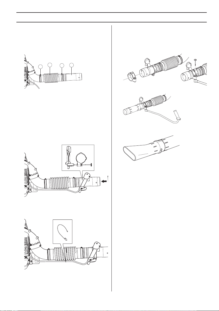
Assembling the blow pipe and control handle
• Connect the blower and control pipe with the flexible
hose. Clamp both ends of the flexible hose in place.
Use the accompanying hardware.
Accessories
Handlebar
Disassemble the intermediate pipe. Disassemble the
knob from the holder and puch the holder on to the holder
pipe. Assemble the knob and tighten.
1
3
1 Flexible hose
2 Control pipe
3 Clamp
4 Clamp
NOTE!
Lubricate the pipes a little to facilitate assembly.
• Fasten the handle holder to the control pipe and
tighten the knob on the holder. Please make sure to
align the handle holder with the convex of the control
pipe.
• Adjust the position and angle to achieve a comfortable
working position, and tighten.
• Use the clamp to fasten the cabling to the flexible
hose. (BTS)
2
4
Assemble the intermediate pipe.
• If higher air speed is required, the round blow pipe is
replaced by the flat nozzle.
• Connect the straight pipe and pipe end. Push the
pipes together and turn them so they lock.
1155849-49 Rev. 2 2013-03-22
English – 15
FUEL HANDLING
Fuel
CAUTION! The machine is equipped with a two-stroke
engine and must always been run using a mixture of
gasoline and two-stroke engine oil. It is important to
accurately measure the amount of oil to be mixed to
ensure that the correct mixture is obtained. When mixing
small amounts of fuel, even small inaccuracies can
drastically affect the ratio of the mixture.
WARNING! Always ensure there is
adequate ventilation when handling fuel.
!
Gasoline
CAUTION! Always use high grade oil mixed gasoline
(minimum 87 RON).
• This engine is certified to operate on unleaded
gasoline.
• The lowest recommended octane rating is 87. If you
run the engine on lower octane rating than 87 socalled “knocking“ can occur. This leads to an
increased engine temperature, which can result in a
serious engine breakdown.
• When working at continuous high revs a higher octane
rating is recommended. Use good quality unleaded
gasoline.
Two-stroke oil
• For best results and performance use HUSQVARNA
two-stroke oil, which is specially formulated for our
two-stroke engines. Mixture 1:50 (2%).
• If HUSQVARNA two-stroke oil is not available, you
may use another two-stroke oil of good quality that is
intended for air cooled engines. Contact your dealer
when selecting an oil.
• Never use two-stroke oil intended for water-cooled
outboard engines, sometimes referred to as outboard
oil.
• Never use oil intended for four-stroke engines.
Gasoline, litre Two-stroke oil, litre
2% (1:50)
5 0,10
10 0,43/0,20
15 0,6/0,30
20 0,40
US gallon US fl. oz.
1 2 1/2
2 1/2 6 1/2
5 12 7/8
Mixing
• Always mix the gasoline and oil in a clean container
intended for fuel.
• Always start by filling half the amount of the gasoline
to be used. Then add the entire amount of oil. Mix
(shake) the fuel mixture. Add the remaining amount of
gasoline.
• Mix (shake) the fuel mixture thoroughly before filling
the machine’s fuel tank.
• Do not mix more than one month’s supply of fuel at a
time.
• If the machine is not used for some time the fuel tank
should be emptied and cleaned.
• This engine is certified to operate on unleaded
gasoline.
16 – English
1155849-49 Rev. 2 2013-03-22
Fueling
!
FUEL HANDLING
WARNING! Taking the following
precautions, will lessen the risk of fire:
Refuel in a well ventilated area. Never
fuel the machine indoors.
Do not smoke or place hot objects near
fuel.
Always shut off the engine before
refuelling.
Always stop the engine and let it cool for
a few minutes before refuelling.
When refuelling, open the fuel cap slowly
so that any excess pressure is released
gently.
Tighten the fuel cap carefully after
refuelling.
If you have spilled fuel on it. Wipe off the
spillage and allow remaining fuel to
evaporate.
Always move the machine away from the
refuelling area and source before
starting.
• Move the machine at least 10 ft (3 m) from the
refuelling point before starting it.
• Clean the area around the fuel cap. Contamination in
the tank can cause operating problems.
• Ensure that the fuel is well mixed by shaking the
container before filling the tank.
• Check the fuel level before each use and leave space
for the fuel to expand, because the heat from the
engine and the sun may otherwise cause the fuel to
expand and overflow.
1155849-49 Rev. 2 2013-03-22
English – 17
STARTING AND STOPPING
Starting and stopping
WARNING! Always move the machine
away from the refuelling area and source
!
before starting. Place the machine on a
flat surface.
Make sure no unauthorised persons are
in the working area, otherwise there is a
risk of serious personal injury. The safety
distance is 15 metres.
The machine may only be started in its
complete design. If the machine is
started without all the guards fitted there
is a risk of personal injuries.
Cold engine
Ignition: Set the stop switch to the start position. About
one third open.
(2)
(3)
(4)
(1)
1
4
2
3
570, 580 - BTS, BFS
560BTS, BFS
Primer bulb: Press the air purge repeatedly until fuel
begins to fill the bulb. The bulb need not be completely
filled.
Warm engine
Use the same starting procedure as for a cold engine but
without setting the choke control in the choke position.
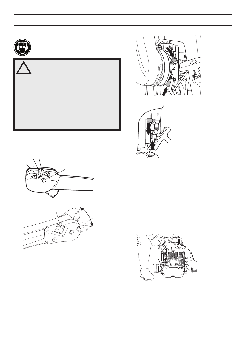
Starting
Hold the body of the machine on the ground using your
left hand (CAUTION! Not with your foot!). Grip the starter
handle, slowly pull out the cord with your right hand until
you feel some resistance (the starter pawls grip), now
quickly and powerfully pull the cord.
It is not allowed to set the stop switch in full throttle
position.
Choke: Set the choke control in the choke position.
18 – English
Never wrap the starter cord around your hand
Repeat pulling the cord until the engine starts. When the
engine starts, return choke control to run position.
CAUTION! Do not pull the star ter cord all the way out and
do not let go of the starter handle when the cord is fully
extended. This can damage the machine.
NOTE!
1155849-49 Rev. 2 2013-03-22
STARTING AND STOPPING
Air is released as soon as the engine is started, even
when idling.
Set the required engine speed with the throttle control.
(2)
(3)
(4)
Allow the engine to warm for a few minutes.
1 Full throttle
2 About one third open.
3 Idle speed
4 Stop switch
Stopping
The engine is stopped by moving the stop switch to the
stop position.
(1)
1
4
2
3
The engine is stopped by switching the ignition off using
the stop switch.
1155849-49 Rev. 2 2013-03-22
English – 19
MAINTENANCE
!
General
Remove the ignition cable and the spark plug to carry out
inspection and maintenance. Keep all parts of your body
away from hot surfaces.
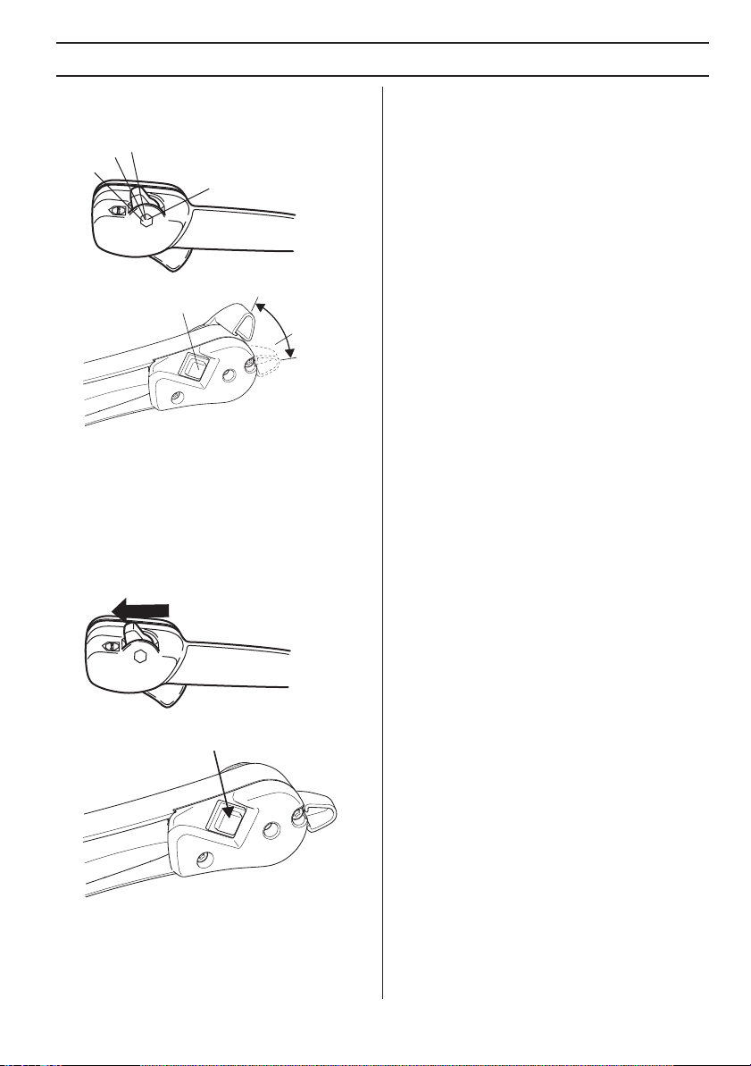
Carburetor
Adjustment of the idle speed
Before any adjustments are made, make sure that the air
filter is clean and the air filter cover is fitted.
The factory idle speed setting is 2,000 rpm. Use the
adjustment screw at the upper edge of the carburettor if
the idle speed has to be adjusted.
Muffler
CAUTION! Never use a machine with a defective muffler.
Check regularly that the muffler is complete and secured
correctly. (1,2) Tighten the screws. 8-10Nm
1
2
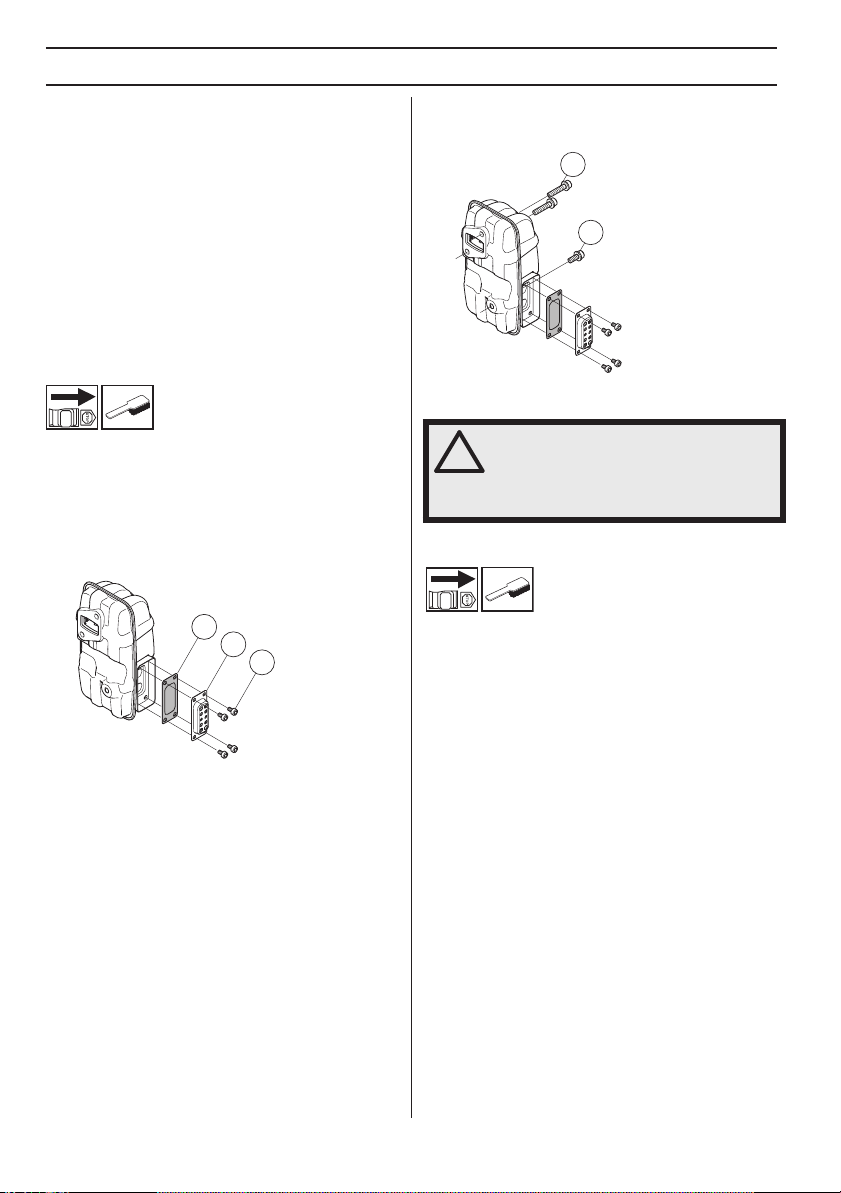
Check that the spark arrester and the exhaust duct are
screwed in place correctly (5). Tighten to 2-3 Nm.
The muffler is designed to reduce the noise level and to
direct the exhaust gases away from the operator. The
exhaust gases are hot and can contain sparks, which may
cause fire if directed against dry and combustible
material.
The muffler is equipped with a special spark arrestor
screen. The spark arrestor screen should be cleaned
once a month. This is best done with a wire brush.
3
4
5
To remove the spark arrestor screen proceed as follows:
• Remove the exhaust duct (4).
• Remove the spark arrester (3).
• Pull out the spark arrestor screen and clean using a
wire brush. Replace the spark arrestor screen if it is
defective.
WARNING! The muffler gets very hot
during use and remain so for some time
after stopping. This also applies at idle
speed. Contact can result in burns to the
skin. Remember the risk of fire!
Cooling system
To keep the working temperature as low as possible the
machine is equipped with a cooling system.
The cooling system consists of:
• Cooling fins on the cylinder.
• Air intake screen
Clean the cooling system with a brush once a week, more
often in demanding conditions. A dirty or blocked cooling
system results in the machine overheating which causes
damage to the piston and cylinder. Check that the nozzles
are not blocked.
20 – English
1155849-49 Rev. 2 2013-03-22
MAINTENANCE
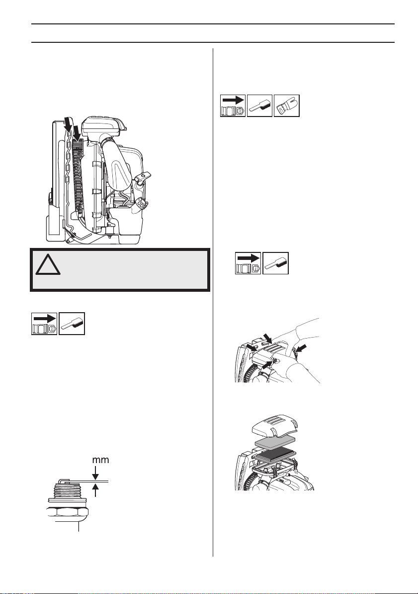
Air intake screen
Check that the air intake is not blocked on all sides
including the underside, for example, by leaves or
rubbish. A clogged air intake reduces the machine’s
blowing capacity and increases the engine’s working
temperature, which can result in engine failure. Stop the
engine and remove the object.
WARNING! Never use the blower if the
screen is not in place. Before use, check
!
that the screen is in place and
undamaged.
Spark plug
CAUTION! Always use the recommended spark plug
type! Use of the wrong spark plug can damage the piston/
cylinder.
Air filter
The air filter must be regularly cleaned to remove dust
and dirt in order to avoid:
• Carburettor malfunctions
• Starting problems
• Loss of engine power
• Unnecessary wear to engine parts
• Excessive fuel consumption.
Clean the filter every 40 hours, or more regularly if
conditions are exceptionally dusty.
Avoid contact with hot surfaces on muffler, cylinder etc.
Contact can result in burns to the skin.
Cleaning the air filter
570, 580 - BTS, BFS
• Loosen the four fasteners holding the air filter cover
and remove the filter. Wash the prefilter in warm soapy
water.
The spark plug condition is influenced by:
• Incorrect carburetor adjustment.
• An incorrect fuel mixture (too much or incorrect type
of oil).
• A dirty air filter.
These factors cause deposits on the spark plug
electrodes, which may result in operating problems and
starting difficulties.
Clean the outside of the spark plug. Remove it and check
the electrode gap. Adjust the gap to 0,6-0,7 mm, or
replace the spark plug. Check that the spark plug is fitted
with a suppressor.
0,6-0,7
1155849-49 Rev. 2 2013-03-22
• Tap the paper filter against a hard surface to shake off
the dust. If the paper filter is still dirty it should be
replaced with a new one.
NOTE!
Do not oil the filter.
English – 21
MAINTENANCE
!
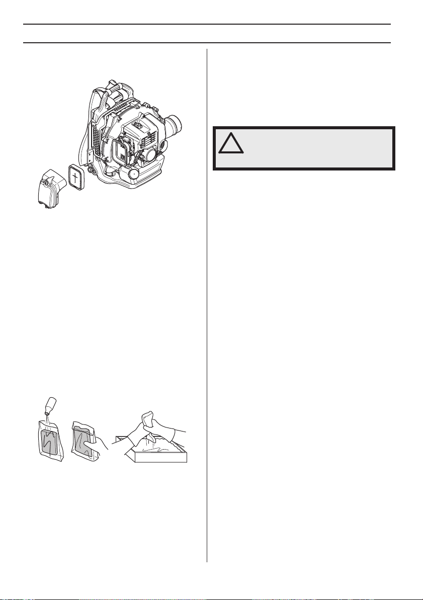
560BTS, BFS
Remove the air filter cover and take out the filter. Wash it
clean in warm, soapy water.
If the machine is used in dusty conditions the air filter
should be soaked in oil. See instructions under the
heading Oiling the air filter.
An air filter that has been in use for a long time cannot be
cleaned completely. The filter must therefore be replaced
with a new one at regular intervals.
must always be replaced.
• Refit the air filter and air filter cover.
Oiling the air filter
560BTS, BFS
Always use special filter oil. Filter oil contains a solvent to
make it spread evenly through the filter. You should
therefore avoid skin contact.
Put the filter in a plastic bag and pour the filter oil over it.
Knead the plastic bag to distribute the oil. Squeeze the
excess oil out of the filter inside the plastic bag and pour
off the excess before fitting the filter to the machine. Never
use common engine oil. This would drain through the filter
quite quickly and collect in the bottom.
A damaged air filter
Shoulder strap
If the shoulder strap is damaged, it may break while in use
and the machine may fall causing personal injury. Follow
the instructions below to replace the shoulder strap.
1 Remove the clamp from the strap.
2 Run the end of the strap through the hanger.
3 Refit the clamp to the strap.
WARNING! Check that the thick round
pin in the clamp is inserted in the strap. If
it is inserted incorrectly it may lead to
personal injury.
22 – English
1155849-49 Rev. 2 2013-03-22

MAINTENANCE
Maintenance schedule
Below you will find some general maintenance instructions. If you need further information please contact your service
workshop.
Maintenance
Clean the outside of the machine. X
Check that the throttle control functions safely. X
Check that the stop switch works correctly. X
Clean the air filter. Replace if necessary. X
Check that nuts and screws are tight. X
Check that there are no fuel leaks from the engine, tank or fuel
lines.
Check the fuel filter from contamination and the fuel hose from
cracks or other defects. Replace if necessary.
Clean or replace the spark arrestor screen on the muffler (only
applies to mufflers without a catalytic converter).
Check that all sides of the air intake screen are not blocked. X
Check the starter and starter cord. X
Check that the vibration damping elements are not damaged. X
Clean the outside of the spark plug. Remove it and check the
electrode gap. Adjust the gap to 0,6-0,7 mm, or replace the spark
plug. Check that the spark plug is fitted with a suppressor.
Clean the machine’s cooling system. X
Clean the outside of the carburettor and the space around it. X
Check all cables and connections. X
Replace the spark plug. Check that the spark plug is fitted with a
suppressor.
Check and clean the spark arrestor screen on the muffler (only
applies to mufflers fitted with a catalytic converter).
Clean the fuel tank. X
IMPORTANT!
Use only HUSQVARNA replacement parts. Use of other brands of replacement parts can cause damage to your unit or
injury to the operator or others. Your warranty does not cover damage or liability caused by the use of accessories and/
or attachments not specifically recommended by HUSQVARNA.
Daily
maintenance
X
X
X
Weekly
maintenance
X
Monthly
maintenance
X
X
1155849-49 Rev. 2 2013-03-22
English – 23

TECHNICAL DATA
Technical data
Technical data 560BTS 560BFS
Motor
Cylinder displacement, cu.in/cm
Idle speed, rpm 2000 2000
Max. engine output, acc. to ISO 8893, kW/ rpm 2.84 / 8100 2.84 / 8100
Catalytic converter muffler No No
Speed-regulated ignition system Ye s Ye s
Emissions Durability Period according to California Air
Resources Board, h.
Ignition system
Spark plug NGK CMR7H NGK CMR7H
Electrode gap, inch/mm 0,024-0,028/0,6-0,7 0,024-0,028/0,6-0,7
Fuel and lubrication system
Fuel tank capacity, US pint/litre 4.6 / 2.2 4.6 / 2.2
Weight
Weight without fuel, Lbs/kg 23.2 / 10,5 23,4/10,6
Sound levels
(see note 1)
Equivalent sound pressure level at the operator’s ear, measured
according to EN15503 dB(A)
Vibration levels
(see note 2)
Equivalent vibration levels (a
according to EN15503, m/s
Fan performance
Max. air velocity vith standard nozzle, m/s / mph: 103.9 / 232 103.9 / 232
Air flow with standard nozzle, m3/min/cfm 17.9 / 632 17.9 / 632
Average air volume at the cover, m3/min / cfm
Note 1: The equivalent sound pressure level value is calculated with a work cycle of a duration of 1/7 for idling and 6/7
for racing. Reported data for equivalent sound pressure level for the machine has a typical statistical dispersion
(standard deviation) of 1 dB(A).
Note 2: The equivalent vibration level value is calculated with a work cycle of a duration of 1/7 for idling and 6/7 for racing.
Reported data for equivalent vibration level has a typical statistical dispersion (standard deviation) of 1 m/s
3
) at handles, measured
hv,eq
2
4.0 / 65.6 4.0 / 65.6
300 300
95 95
2.3 2.5
2
.
24 – English
1155849-49 Rev. 2 2013-03-22

TECHNICAL DATA
Technical data 570BTS 570BFS 580BTS 580BFS
Motor
Cylinder displacement, cu.in/cm
Idle speed, rpm 2000 2000 2000 2000
Max. engine output, acc. to ISO 8893, kW/ rpm 2.94 / 8000 2.94 / 8000 3.13 / 7200 3.13 / 7200
Catalytic converter muffler No No No No
Speed-regulated ignition system Ye s Ye s Ye s Ye s
Emissions Durability Period according to California Air
Resources Board, h.
Ignition system
Spark plug
Electrode gap, inch/mm
Fuel and lubrication system
Fuel tank capacity, US pint/litre 4,6/2,2 4,6/2,2 5,5/2,6 5,5/2,6
Weight
Weight without fuel, Lbs/kg 24,5/11,1 24,9/11,3 25,8/11,7 26,0/11,8
Sound levels
(see note 1)
Equivalent sound pressure level at the operator’s ear, measured
according to EN15503 dB(A)
Vibration levels
(see note 2)
Equivalent vibration levels (a
according to EN15503, m/s
Fan performance
Max. air velocity vith standard nozzle, m/s / mph: 106/236 106/236 92/206 92/206
Air flow with standard nozzle, m3/min/cfm 21,8/770 21,8/770 25,7/908 25,7/908
Average air volume at the cover, m3/min / cfm 27,5/972 27,5/972 29/1024 29/1024
Note 1: The equivalent sound pressure level value is calculated with a work cycle of a duration of 1/7 for idling and 6/7
for racing. Reported data for equivalent sound pressure level for the machine has a typical statistical dispersion
(standard deviation) of 1 dB(A).
Note 2: The equivalent vibration level value is calculated with a work cycle of a duration of 1/7 for idling and 6/7 for racing.
Reported data for equivalent vibration level has a typical statistical dispersion (standard deviation) of 1 m/s
3
) at handles, measured
hv,eq
2
65.6 65.6 75.6 75.6
300 300 300 300
NGK
CMR7H
0,024-0,028/
0,6-0,7
NGK
CMR7H
0,024-0,028/
0,6-0,7
NGK
CMR7H
0,024-0,028/
0,6-0,7
NGK
CMR7H
0,024-0,028/
0,6-0,7
99 99 100 100
1,8 5,0 1,6 3,3
2
.
1155849-49 Rev. 2 2013-03-22
English – 25

FEDERAL AND CALIFORNIA EMISSIONS CONTROL WARRANTY STATEMENT
IMPORTANT: This product is compliant with U.S. EPA
Phase 3 regulations for exhaust and evaporative
emissions. To ensure EPA Phase 3 compliance, we
recommend using only genuine Husqvarna brand
replacement parts. Use of non-compliant replacement
parts is a violation of federal law.
YOUR WARRANTY RIGHTS AND OBLIGATIONS
The EPA (U.S. Environmental Protection Agency), CARB
(California Air Resources Board), Environment Canada
and Husqvarna Forest & Garden are pleased to explain
the emissions control system’s warranty on your 20132014* small off-road engine. In U.S. and Canada, new
equipment that use small off-road engines must be
designed, built, and equipped to meet the applicable
Federal or Californian stringent anti-smog standards.
Husqvarna Forest & Garden must warrant the emissions
control system on your small off-road engine for the
period listed below provided there has been no abuse,
neglect or improper maintenance of your equipment. Your
emissions control system may include parts such as the
carburetor, ignition system, catalytic converter, fuel tank,
filters and other associated components. Also, included
may be hoses, belts, connectors, sensors, and other
emission-related assemblies. Where a warrantable
condition exists, Husqvarna Forest & Garden will repair
your small off-road engine at no cost to you including
diagnosis, parts and labor.
MANUFACTURER′S WARRANTY
COVERAGE
The emissions control system is warranted for two years.
If any emissions-related part on your equipment is
defective, the part will be repaired or replaced by
Husqvarna Forest & Garden.
OWNER′S WARRANTY
RESPONSIBILITIES
• As the small off-road engine owner, you are
responsible for performance of the required
maintenance listed in your operator’s manual.
Husqvarna Forest & Garden recommends that you
retain all receipts covering maintenance on your small
off-road engine, but Husqvarna Forest & Garden
cannot deny warranty solely for the lack of receipts or
your failure to ensure the performance of all
scheduled maintenance.
• As the small off-road engine owner, you should
however be aware that Husqvarna Forest & Garden
may deny you warranty coverage if your small off-road
engine or a part has failed due to abuse, neglect, or
improper maintenance or unapproved modifications.
• You are responsible for presenting your small off-road
engine to a Husqvarna Forest & Garden distribution
center or service center as soon as the problem
exists. The warranty repairs should be completed in a
reasonable amount of time, not to exceed 30 days. If
you have any questions regarding your warranty
coverage, you should contact Husqvarna Forest &
Garden at 1-800-438-7297 or send e-mail
correspondence to emission.warranty@us.hvwan.net
WARRANTY COMMENCEMENT DATE
The warranty period begins on the date the engine or
equipment is delivered to an ultimate purchaser.
LENGTH OF COVERAGE
Husqvarna Forest & Garden warrants to the ultimate
purchaser and each subsequent owner that the engine or
equipment is designed, built, and equipped so as to
conform with all applicable regulations adopted by EPA
and CARB, and is free from defects in materials and
workmanship that causes the failure of a warranted part
for a period of two years.
WHAT IS COVERED
REPAIR OR REPLACEMENT OF PARTS Repair or
replacement of any warranted part under the warranty
must be performed at no charge to the owner at a
warranty station. Warranty services or repairs will be
provided at all Husqvarna Forest & Garden distribution
centers that are franchised to service the subject engines.
Throughout the emissions warranty period of two years,
Husqvarna Forest & Garden must maintain a supply of
warranted parts sufficient to meet the expected demand
for such parts.
WARRANTY PERIOD Any warranted part that is
scheduled for replacement as required in the
maintenance schedule, is warranted for the period of time
prior to the first scheduled replacement point for that part.
If the part fails prior to the first scheduled replacement,
the part will be repaired or replaced by Husqvarna Forest
& Garden at no cost. Any such part repaired or replaced
under warranty is warranted for the remainder of the
period prior to the first scheduled replacement point for
the part. Any warranted part that is not scheduled for
replacement as required in the maintenance schedule, is
warranted for two years. If any such part fails during the
period of warranty coverage, it will be repaired and
replaced by Husqvarna Forest & Garden at no cost. Any
such part repaired or replaced under the warranty is
warranted for the remaining warranty period. Any
warranted part that is scheduled only for regular
inspection in the maintenance schedule will be warranted
for a period of two years. A statement in such written
instructions to the effect of ”repair or replace as
necessary” will not reduce the period of warranty
coverage. Any such part repaired or replaced under
warranty will be warranted for the remaining warranty
period.
DIAGNOSIS The owner must not be charged for
diagnostic labor that leads to the determination that a
warranted part is in fact defective, provided that such
diagnostic work is performed at a warranty station.
26 – English
1155849-49 Rev. 2 2013-03-22

FEDERAL AND CALIFORNIA EMISSIONS CONTROL WARRANTY STATEMENT
CONSEQUENTIAL DAMAGES Husqvarna Forest &
Garden is liable for damages to other engine components
proximately caused by a failure under warranty of any
warranted part.
EMISSION WARRANTY PARTS LIST
1 Carburetor and internal parts
2 Intake pipe, airfilter holder and carburetor bolts.
3 Airfilter and fuelfilter covered up to maintenance
schedule.
4 Spark Plug, covered up to maintenance schedule
5 Ignition Module
6 Fuel tank, line and cap
WHAT IS NOT COVERED
All failures caused by abuse, neglect or improper
maintenance are not covered.
ADD -ON OR MODIFIED PARTS
Add-on or modified parts that are not exempted by CARB
or EPA may not be used. The use of any non-exempted
add-on or modified parts will be grounds for disallowing a
warranty claim. Husqvarna Forest & Garden will not be
liable to warrant failures of warranted parts caused by the
use of a non-exempted add-on or modified part.
HOW TO FILE A CLAIM
If you have any questions regarding your warranty rights
and responsibilities, you should contact your nearest
authorized servicing dealer or call Husqvarna Forest &
Garden at 1-800-438-7297 or send e-mail
correspondence to emission.warranty@us.hvwan.net
WHERE TO GET WARRANTY SERVICE
Warranty services or repairs are provided through all
Husqvarna Forest & Garden authorized servicing dealers.
MAINTENANCE, REPLACEMENT AND REPAIR OF EMISSION-RELATED PARTS
Any replacement part may be used in the performance of
any warranty maintenance or repairs and must be
provided without charge to the owner. Such use will not
reduce the warranty obligations of the manufacturer.
MAINTENANCE STATEMENT
The owner is responsible for the performance of all
required maintenance, as defined in the operator’s
manual.
*Current and following model year will be updated
annually in the warranty statement provided to the
consumer. For example, in 2013 model year, 2013-2014
will be specified.
1155849-49 Rev. 2 2013-03-22
English – 27

EXPLICATION DES SYMBOLES
Symboles
AVERTISSEMENT! La machine
utilisée de manière imprudente ou
inadéquate peut devenir un outil
dangereux, pouvant causer des
blessures graves voire mortelles à
l’utilisateur et aux autres personnes
présentes.
Lire attentivement et bien assimiler
le manuel d’utilisation avant
d’utiliser la machine.
Toujours utiliser:
• Protecteur d’oreilles
• Des protège-yeux homologués
Les autres symboles/autocollants présents sur la
machine concernent des exigences de certification
spécifiques à certains marchés.
Couper le moteur avant tout contrôle ou
réparation en plaçant le bouton d’arrêt
sur la position STOP.
Toujours utiliser des gants de
protection.
Un nettoyage régulier est indispensable.
Examen visuel.
Au besoin, utiliser des gants.
L'aspiro-souffleur peut projeter
violemment des objets pouvant
être renvoyés vers l'utilisateur.
Ceci peut provoquer des
blessures graves aux yeux si
l'équipement de protection
personnelle recommandé n'est
pas utilisé.
L’opérateur du souffleur
doit veiller à ce
qu’aucune personne ou
animal ne se trouve à
moins de 15 mètres.
Lorsque plusieurs opérateurs partagent le même lieu de
travail la distance de sécurité doit être de 15 mètres au
minimum.
Utiliser une protection respiratoire
dans les environnements
poussiéreux.
Maintenez toute partie du corps
loin des surfaces chaudes.
Porter des lunettes protectrices ou une
visière.
Remplissage d’essence.
Commande de starter en position ”ouvert”.
Commande de starter en position ”fermé”.
28 – French
1155849-49 Rev. 2 2013-03-22

SOMMAIRE
!
!
!
Sommaire Contrôler les points suivants
EXPLICATION DES SYMBOLES
Symboles .............................................................. 28
SOMMAIRE
Sommaire ............................................................. 29
Contrôler les points suivants avant la mise en
marche: .................................................................
INTRODUCTION
Cher client, ........................................................... 30
QUELS SONT LES COMPOSANTS?
Quels sont les composants de l'aspiro-souffleur? 31
Quels sont les composants de l'aspiro-souffleur? 32
Quels sont les composants de l'aspiro-souffleur? 33
INSTRUCTIONS GÉNÉRALES DE SÉCURITÉ
Généralités ........................................................... 34
INSTRUCTIONS DE SÉCURITÉ
Équipement de protection personnelle ................. 36
Équipement de sécurité de la machine ................ 36
Contrôle, maintenance et entretien des
équipements de sécurité de la machine ...............
Méthodes de travail .............................................. 39
MONTAGE
Montage du tube de soufflage et de la poignée de
commande ............................................................
MANIPULATION DU CARBURANT
Carburant .............................................................. 42
Remplissage de carburant .................................... 43
DÉMARRAGE ET ARRÊT
Démarrage et arrêt ............................................... 44
ENTRETIEN
Généralités ........................................................... 46
Carburateur .......................................................... 46
Silencieux ............................................................. 46
Système de refroidissement ................................. 46
Grille d'entrée d'air ............................................... 47
Bougie .................................................................. 47
Filtre à air ............................................................. 47
Bretelle d’épaule ................................................... 48
Schéma d’entretien .............................................. 49
CARACTÉRISTIQUES TECHNIQUES
Caractéristiques techniques ................................. 50
DÉCLARATION DE GARANTIE CONTRÔLE
DES ÉMISSIONS EN CALIFORNIE ET AU
NIVEAU FÉDÉRAL
VOS DROITS ET OBLIGATIONS EN
GARANTIE ........................................................... 52
avant la mise en marche:
Lire attentivement le manuel d’utilisation.
AVERTISSEMENT! Une exposition
prolongée au bruit risque de causer des
29
38
41
Husqvarna AB travaille continuellement au
développement de ses produits et se réserve le droit d’en
modifier, entre autres, la conception et l’aspect sans
préavis.
La machine est conçue uniquement pour le nettoyage des
pelouses, des allées, des voies en asphalte et similaires.
Si vous avez besoin d’aide, appelez le 704-921-7000 ou
connectez-vous à notre site: www.husqvarna.com
lésions auditives permanentes. Toujours
utiliser des protecteurs d'oreille agréés.
AVERTISSEMENT! Ne jamais modifier
sous aucun prétexte la machine sans
l’autorisation du fabricant. N’utiliser que
des accessoires et des pièces d’origine.
Des modifications non-autorisées et
l’emploi d’accessoires non-homologués
peuvent provoquer des accidents graves
et même mortels, à l’utilisateur ou
d’autres personnes.
Votre garantie ne couvre ni les
dommages ni la responsabilité
qu’entraîne l’utilisation de pièces ou
d’accessoires non autorisés.
AVERTISSEMENT! Un aspiro-souffleur
utilisé de manière erronée ou négligente
peut être un outil dangereux pouvant
occasionner des blessures personnelles
graves, voire mortelles. Il importe donc
de lire attentivement et de bien assimiler
le contenu de ce manuel d'utilisation.
Jan. 2011
1155849-49 Rev. 2 2013-03-22
French – 29

INTRODUCTION
Cher client,
Félicitations pour ce choix d’un produit Husqvarna. Husqvarna a vu le jour en 1689 lorsque le roi Karl XI décida de
construire un arsenal pour la fabrication des mousquets au bord de la rivière Huskvarna. Le choix de l’emplacement
était logique puisque la rivière Huskvarna servait à produire de l’énergie hydraulique et constituait donc une sorte de
centrale hydraulique. En plus de 300 ans d’existence, l’usine Husqvarna a fabriqué de nombreux produits, depuis les
cuisinières à bois jusqu’aux équipements de cuisine modernes, sans oublier les machines à coudre, les bicyclettes, les
motos, etc. La première tondeuse à moteur a été lancée en 1956, suivie en 1959 de la première tronçonneuse. C’est
dans ce secteur que Husqvarna est actif aujourd’hui.
Husqvarna est aujourd’hui un des plus grands fabricants du monde de produits destinés à l’entretien des forêts et des
jardins. La qualité et les performances sont nos priorités. Notre concept d’affaires est de développer, fabriquer et
commercialiser des produits à moteur pour l’entretien des forêts et des jardins et pour les entreprises de construction
et d’aménagement des sols. L’objectif d’Husqvarna est aussi d’être à la pointe du progrès en matière d’ergonomie, de
facilité d’utilisation, de sécurité et de protection de l’environnement; un grand nombre d’innovations ont été développées
pour améliorer les produits dans ces domaines.
Nous sommes persuadés que vous apprécierez la qualité et les performances de nos produits pendant de longues
années. L’achat d’un de nos produits vous garantit une assistance professionnelle au niveau du service et des
réparations en cas de besoin. Si la machine n’a pas été achetée chez un de nos revendeurs autorisés, demandez à un
revendeur l’adresse de l’atelier d’entretien le plus proche.
Nous espérons que cette machine vous donnera toute satisfaction et qu’elle vous accompagnera pendant de longues
années. N’oubliez pas que ce manuel d’utilisation est important. En suivant les instructions qu’il contient (utilisation,
révision, entretien, etc.), il est possible d’allonger considérablement la durée de vie de la machine et d’augmenter sa
valeur sur le marché de l’occasion. En cas de vente de la machine, ne pas oublier de remettre le manuel d’utilisation au
nouveau propriétaire.
Nous vous remercions d'utiliser un produit Husqvarna !
Husqvarna AB travaille continuellement au développement de ses produits et se réserve le droit d’en modifier, entre
autres, la conception et l’aspect sans préavis.
30 – French
1155849-49 Rev. 2 2013-03-22

QUELS SONT LES COMPOSANTS?
14
3
4
20
18
8
9
19
2
25
1
5
26
12
13
Quels sont les composants de l'aspiro-souffleur? 560BTS, 560BFS
1 Cadre
2 Harnais
3 Capot de moteur
4 Coque de ventilateur
5 Grille d'entrée d'air
6 Ventilateur
7 Filtre à air
8 Poignée de lanceur
9 Réservoir d’essence
10 Coussin
11 Bougie
12 Système anti-vibrations
13 Commande de starter
14 Poignée de commande/Poignée de manoeuvre(BTS)
15
19
22
21
7
15 Manette de réglage. Arrêtez interrupteur placé
derrière le levier (BFS)
16 Bouton d'arrêt avec réglage de la position
d'accélération (BTS)
17 Commande de l’accélération
18 Guidon (Accessoires)
19 Coude
20 Collier de serrage
21 Tuyau flexible
22 Tube de manoeuvre
23 Collier de serrage
24 Tube intermédiaire
25 Tube de soufflage
26 Manuel d’utilisation
27 Clé universelle
28 Poignée de commande/Poignée de manoeuvre (BFS)
16
23
24
12
10
11
17
6
1155849-49 Rev. 2 2013-03-22
French – 31

QUELS SONT LES COMPOSANTS?
3
4
20
18
19
14
15
25
19
8
26
Quels sont les composants de l'aspiro-souffleur? 570BTS, 580BTS
1 Cadre
2 Harnais
3 Capot de moteur
4 Coque de ventilateur
5 Grille d'entrée d'air
6 Ventilateur
7 Filtre à air
8 Poignée de lanceur
9 Réservoir d’essence
10 Coussin
11 Bougie
12 Système anti-vibrations
13 Commande de starter
14 Poignée de commande/Poignée de manoeuvre
9
27
10
2
1
5
12
13
22
7
11
15 Bouton d'arrêt avec réglage de la position
d'accélération
16 Commande de l’accélération
17 Guidon (Accessoires)
18 Coude
19 Collier de serrage
20 Tuyau flexible
21 Tube de manoeuvre
22 Collier de serrage
23 Tube intermédiaire
24 Tube de soufflage
25 Buse plate (Accessoires)
26 Manuel d’utilisation
27 Clé universelle
16
21
17
23
6
24
12
32 – French
1155849-49 Rev. 2 2013-03-22

QUELS SONT LES COMPOSANTS?
3
4
20
18
19
14
25
19
8
26
27
Quels sont les composants de l'aspiro-souffleur? 570BFS, 580BFS
1 Cadre
2 Harnais
3 Capot de moteur
4 Coque de ventilateur
5 Grille d'entrée d'air
6 Ventilateur
7 Filtre à air
8 Poignée de lanceur
9 Réservoir d’essence
10 Coussin
11 Bougie
12 Système anti-vibrations
13 Commande de starter
14 Poignée de commande/Poignée de manoeuvre
9
16
15
10
2
1
5
12
7
11
13
15 Bouton d'arrêt avec réglage de la position
d'accélération
16 Commande de l’accélération
17 Guidon (Accessoires)
18 Coude
19 Collier de serrage
20 Tuyau flexible
21 Tube de manoeuvre
22 Collier de serrage
23 Tube intermédiaire
24 Tube de soufflage
25 Buse plate (Accessoires)
26 Manuel d’utilisation
27 Clé universelle
21
17
23
6
24
12
1155849-49 Rev. 2 2013-03-22
French – 33

INSTRUCTIONS GÉNÉRALES DE SÉCURITÉ
Généralités
IMPORTANT!
La machine est conçue uniquement pour le nettoyage
des pelouses, des allées, des voies en asphalte et
similaires.
Effectuez une inspection générale de la machine avant
de l’utiliser, voir le Calendrier de maintenance.
Éviter d’utiliser la machine en cas de fatigue,
d’absorption d’alcool ou de prise de médicaments
susceptibles d’affecter l’acuité visuelle, le jugement ou
la maîtrise du corps.
Utiliser les équipements de protection personnelle. Voir
au chapitre ”Équipement de protection personnelle”.
Ne jamais utiliser une machine qui a été modifiée au
point de ne plus être conforme au modèle original.
Ne jamais utiliser une machine qui n’est pas en parfait
état de marche. Suivre dans ce manuel d’utilisation les
instructions de maintenance, de contrôle et d’entretien.
Certaines mesures de maintenance et d’entretien
doivent être confiées à un spécialiste dûment formé et
qualifié. Voir au chapitre Entretien.
Tous les carters et toutes les protections doivent être
montés avant le démarrage. Vérifier que le chapeau de
bougie et le câble d’allumage ne sont pas endommagés
afin d'éviter tout risque de choc électrique.
L’opérateur du souffleur doit veiller à ce qu’aucune
personne ou animal ne se trouve à moins de 15 mètres.
Lorsque plusieurs opérateurs partagent le même lieu de
travail la distance de sécurité doit être de 15 mètres au
minimum.
Ne jamais laisser un enfant utiliser la machine.
Ne jamais laisser d’autres personnes utiliser la machine
sans s’être assuré au préalable que ces personnes ont
bien compris le contenu du mode d’emploi.
Vérifiez toujours qu'aucun objet n'obstrue la grille
d'entrée d'air avant de commencer le travail.
Ne retirez jamais la grille d'entrée d'air.
En cas d'urgence, dégagez-vous de la machine en
ouvrant le ceinturon et la ceinture de poitrine et laissez
la machine tomber vers l'arrière.
Toujours consulter les autorités locales pour s’assurer
d’appliquer les règlements en vigueur.
Maintenez toute partie du corps loin des surfaces
chaudes.
Démarrage
• Ne jamais mettre la machine en marche à l’intérieur.
Les gaz d’échappement du moteur sont nocifs.
• Inspecter les environs et s’assurer qu’aucune
personne et qu’aucun animal ne peut se trouver en
contact avec le jet.
• Placer la machine sur le sol et pousser le corps de la
machine contre le sol avec la main gauche
(REMARQUE! Pas avec le pied). Saisir ensuite la
poignée du lanceur avec la main droite et tirer
plusieurs fois rapidement et avec force .
Sécurité carburant
• Utiliser un bidon d’essence comportant un dispositif
d’arrêt de remplissage automatique.
• Ne jamais effectuer le remplissage de la machine
lorsque le moteur tourne. Arrêter le moteur et le
laisser refroidir pendant quelques minutes avant de
faire le plein.
• Veiller à une bonne aération lors du remplissage et du
mélange de carburant (essence et huile 2 temps).
• Éviter tout contact de la peau avec du carburant. Le
carburant a un effet irritant sur la peau et peut aussi
entraîner des altérations dermiques.
• Avant de mettre la machine en marche, la déplacer à
au moins 3 mètres de l’endroit où a été fait le plein.
!
34 – French
AVERTISSEMENT! Cette machine génère
un champ électromagnétique en
fonctionnement. Ce champ peut dans
certaines circonstances perturber le
fonctionnement d’implants médicaux
actifs ou passifs. Pour réduire le risque
de blessures graves ou mortelles, les
personnes portant des implants
médicaux doivent consulter leur
médecin et le fabricant de leur implant
avant d’utiliser cette machine.
• Ne jamais démarrer la machine:
-
Si du carburant a été renversé. Essuyer soigneusement
toute trace et laisser les restes d’essence s’évaporer.
- Si vous avez renversé du carburant sur vous ou sur vos
vêtements, changez de vêtements. Lavez les parties du
corps qui ont été en contact avec le carburant. Utilisez de
l’eau et du savon.
- S’il y a fuite de carburant. Vérifier régulièrement que le
bouchon du réservoir et la conduite de carburant ne fuient
pas.
1155849-49 Rev. 2 2013-03-22

INSTRUCTIONS GÉNÉRALES DE SÉCURITÉ
Transport et rangement
• Transporter et ranger la machine et le carburant de
façon à éviter que toute fuite ou émanation éventuelle
entre en contact avec une flamme vive ou une
étincelle: machine électrique, moteur électrique,
contact/interrupteur électrique ou chaudière.
•
Lors du stockage et du transport de carburant, toujours
utiliser un récipient homologué et conçu à cet effet.
• Lors des remisages de la machine, vider le réservoir
de carburant. S’informer auprès d’une station-service
comment se débarrasser du carburant résiduel. Videz
le réservoir de carburant et appuyez sur l'amorceur
jusqu'à ce que le réservoir soit complètement vide.
Retirez la bougie et versez une cuillerée d'huile deux
temps dans le cylindre. Retournez le moteur deuxtrois fois, puis remettez la bougie en place.
• Avant de remiser la machine pour une période
prolongée, veiller à ce qu'elle soit bien nettoyée et que
toutes les mesures d'entretien aient été effectuées.
• Sécurisez la machine pendant le transport.
• Rangez la machine dans un endroit sec, frais, bien
aéré et exempt de poussières. Ranger la machine
hors de portée des enfants.
AVERTISSEMENT! Manipuler le
carburant avec précaution. Penser aux
!
risques d’incendie, d’explosion et
d’inhalation.
Réglage du harnais
AVERTISSEMENT! Le harnais doit
toujours être utilisé en cas de travail
!
avec la machine. Sinon, il est impossible
d’effectuer le travail en toute sécurité, ce
qui risque de causer des blessures à
l’utilisateur et aux autres.
Assurez-vous que la ceinture est fermée
et réglée correctement.
Si vous n'utilisez pas la ceinture,
assurez-vous de la retirer de l'unité et de
la ranger. La ceinture risque sinon de
coincer et de faire basculer l'unité.
Une ceinture non fermée risquerait de se
coincer ou d'être aspirée dans le
ventilateur de la machine.
Un harnais adapté à la machine facilite considérablement
le travail. Régler le harnais de manière à obtenir la
position de travail la plus confortable possible..
Tendre les courroies latérale afin que la pression soit
répartie de manière égale sur les épaules..
Serrez et ajustez la ceinture de poitrine afin d’obtenir la
position de travail la plus confortable.
NOTE!
560BTS, BFS ne possède ni ceinture de poitrine, ni
ceinture.
1155849-49 Rev. 2 2013-03-22
French – 35

INSTRUCTIONS DE SÉCURITÉ
!
Équipement de protection personnelle
AVERTISSEMENT! Un équipement de
protection personnelle homologué doit
!
impérativement être utilisé lors de tout
travail avec la machine. L’équipement de
protection personnelle n’élimine pas les
risques mais réduit la gravité des
blessures en cas d’accident. Demander
conseil au concessionnaire afin de
choisir un équipement adéquat. Lire
attentivement et bien assimiler le manuel
d’utilisation avant d’utiliser la machine.
AVERTISSEMENT! Soyez toujours
attentifs aux signaux d’alerte ou aux
!
appels en portant des protège-oreilles.
Enlevez-les sitôt le moteur arrêté.
• Au besoin, utiliser des gants.
• Utiliser des bottes antidérapantes et stables.
• Porter des vêtements fabriqués dans un matériau
résistant à la déchirure, éviter les vêtements
excessivement amples qui risqueraient de se prendre
dans les broussailles et les branches. Toujours utiliser
des pantalons longs et robustes. Ne pas porter de
bijoux, de shorts ou de sandales, et ne pas marcher
pieds-nus. Veiller à ce que les cheveux ne tombent
pas sur les épaules.
• Utiliser une protection respiratoire dans les
environnements poussiéreux.
• Porter des protège-oreilles ayant un effet atténuateur
suffisant.
• Toujours porter des protège-yeux homologués.
L’usage d’une visière doit toujours s’accompagner du
port de lunettes de protection homologuées. Par
lunettes de protection homologuées, on entend celles
qui sont en conformité avec les normes ANSI Z87.1
(États-Unis) ou EN 166 (pays de l’UE). Les branches
ou objets projetés peuvent causer des blessures aux
yeux.
36 – French
• Une trousse de premiers secours doit toujours être
disponible.
Équipement de sécurité de la machine
Ce chapitre présente les équipements de sécurité de la
machine, leur fonction, comment les utiliser et les
maintenir en bon état. Voir au chapitre Quels sont les
composants? pour trouver leur emplacement sur la
machine.
AVERTISSEMENT! Ne jamais utiliser une
machine dont les équipements de
sécurité sont défectueux. Suivre les
directives de maintenance, d’entretien et
les instructions de réparation indiquées
dans ce chapitre.
1155849-49 Rev. 2 2013-03-22

INSTRUCTIONS DE SÉCURITÉ
!
!
Bouton d’arrêt
Le bouton d’arrêt est utilisé pour arrêter le moteur.
Retirez le câble d'allumage et la bougie pour effectuer
toute opération de contrôle ou d'entretien.
Système anti-vibrations
La machine est équipée d’un système anti-vibrations
conçu pour assurer une utilisation aussi confortable que
possible.
x2
AVERTISSEMENT! Une exposition
excessive aux vibrations peut entraîner
!
des troubles circulatoires ou nerveux
chez les personnes sujettes à des
troubles cardio-vasculaires. Consulter
un médecin en cas de symptômes liés à
une exposition excessive aux vibrations.
De tels symptômes peuvent être:
engourdissement, perte de sensibilité,
chatouillements, picotements, douleur,
faiblesse musculaire, décoloration ou
modification épidermique. Ces
symptômes affectent généralement les
doigts, les mains ou les poignets. Les
risques peuvent augmenter à basses
températures.
Silencieux
Le silencieux est conçu pour réduire au maximum le
niveau sonore et détourner les gaz d’échappement loin
de l’utilisateur.
Le risque d'incendie est important dans les pays au climat
chaud et sec. C'est pourquoi nous avons équipé le
silencieux d'une grille antiflamme monté à l'intérieur du
siilencieux.
En ce qui concerne le silencieux, il importe de bien suivre
les instructions de contrôle, de maintenance et
d’entretien. Voir les instructions au chapitre Contrôle,
maintenance et entretien des équipements de sécurité de
la machine.
AVERTISSEMENT!
N’oubliez pas que: Les gaz
d’échappement du moteur contiennent
de l’oxyde de carbone pouvant
provoquer l’intoxication. Ne jamais
démarrer ou utiliser la machine à
l’intérieur d’un bâtiment ou dans un lieu
mal aéré.
Les gaz d’échappement du moteur sont
très chauds et peuvent contenir des
étincelles pouvant provoquer un
incendie. Par conséquent, ne jamais
démarrer la machine dans un local clos
ou à proximité de matériaux
inflammables!
AVERTISSEMENT! L’intérieur du
silencieux contient des produits
chimiques pouvant être cancérigènes.
Eviter tout contact avec ces éléments si
le silencieux est endommagé.
1155849-49 Rev. 2 2013-03-22
French – 37

INSTRUCTIONS DE SÉCURITÉ
!
Contrôle, maintenance et entretien des équipements de sécurité de la machine
AVERTISSEMENT! L’entretien et la
réparation de la machine exigent une
!
formation spéciale. Ceci concerne
particulièrement l’équipement de sécurité
de la machine. Si les contrôles suivants
ne donnent pas un résultat positif,
s’adresser à un atelier spécialisé. L’achat
de l’un de nos produits offre à l’acheteur
la garantie d’un service et de réparations
qualifiés. Si le point de vente n’assure pas
ce service, s’adresser à l’atelier spécialisé
le plus proche.
Bouton d’arrêt
•
Mettre le moteur en marche et s’assurer qu’il s’arrête
lorsque le bouton d’arrêt est amené en position d’arrêt.
Le moteur s’arrête lorsque l’on coupe l’allumage en
pressant sur le bouton d’arrêt.
• Vérifier que les éléments anti-vibrations sont entiers
et solidement fixés.
Silencieux
• Ne jamais utiliser une machine dont le silencieux est
défectueux.
• Vérifier régulièrement la fixation du silencieux dans la
machine.
Système anti-vibrations
• Contrôler régulièrement les éléments anti-vibrations
afin de détecter toute éventuelle fissure ou
déformation. Les remplacer s'ils sont endommagés.
x2
38 – French
• Le silencieux de la machine est équipé d'une grille
antiflamme qui doit être nettoyé régulièrement. Voir la
section Silencieux du chapitre Entretien. Une grille
antiflamme colmaté risque de causer la surchauffe du
moteur et de provoquer de sérieuses avaries du
moteur. Ne jamais utiliser un silencieux avec une grille
antiflamme défectueuse.
AVERTISSEMENT! Ne jamais utiliser une
machine dont les équipements de
sécurité sont défectueux. Contrôler et
entretenir les équipements de sécurité
de la machine conformément aux
instructions données dans ce chapitre.
Si les contrôles ne donnent pas de
résultat positif, confier la machine à un
atelier spécialisé.
Filtre à air
N'utilisez jamais l'aspiro-souffleur sans filtre à air ou avec
un élément du filtre endommagé ou déformé ; un air
poussiéreux non filtré peut rapidement détruire le moteur.
1155849-49 Rev. 2 2013-03-22

INSTRUCTIONS DE SÉCURITÉ
Méthodes de travail
IMPORTANT! Cette section décrit les règles de sécurité
de base à observer lors de tout travail avec le souffleur.
Dans l’éventualité d’une situation rendant la suite du
travail incertaine, consulter un expert. S’adresser au
revendeur ou à l’atelier de réparation. Évitez les tâches
pour lesquelles vous ne vous sentez pas suffisamment
qualifié.
Respecter les voisins en évitant d’utiliser la machine à
des heures indues comme par exemple tard le soir ou tôt
le matin. Afin de réduire le niveau sonore, limitez le
nombre de machines utilisées en même temps. Lire
attentivement et suivre les conseils ci-dessous afin de
déranger les voisins le moins possible.
• Utiliser le souffleur sur le régime le plus faible.
L’utilisation du régime maximal est rarement
nécessaire et de nombreux travaux peuvent être
effectués à demi-régime. L’utilisation d’un régime plus
faible signifie moins de bruit et moins de poussière. Il
permet également de contrôler plus facilement les
déchets à rassembler/déplacer.
• Utiliser un râteau ou un balai pour dégager les
déchets enfouis dans le sol.
• Maintenir l’embout du tube de soufflage le plus près
possible du sol. Utilisez toute la longueur du tube de
soufflage afin de maintenir le courant d'air proche du
sol.
• Nettoyer une fois le travail terminé. S’assurer que des
déchets n’ont pas été accidentellement projetés dans
un jardin voisin.
• N’utilisez la machine qu’àdes heures raisonnables en
éitant de travailler tôt le matin ou tard le soir afin ne
pas déranger les voisins. Respectez les horaires
recommandés par les directives locales.
AVERTISSEMENT! Soyez conscient de
l'environnement qui vous entoure. Si une
!
personne s’approche de votre zone de
travail, ramenez la commande
d’accélération sur le régime le plus faible
jusqu’à ce que cette personne se trouve
de nouveau à une distance de sécurité.
Éloignez l'aspiro-souffleur des
personnes, des animaux, des aires de
jeux, des fenêtres ouvertes, des voitures,
etc.
• Laisser refroidir le moteur avant de remplir de
carburant.
• Maintenez toute partie du corps loin des surfaces
chaudes.
• Si la machine prend feu ou si un autre type d'urgence
se produit, qui vous oblige à vous dégager de la
machine, ouvrez les bretelles du harnais et laissez la
machine tomber vers l'arrière.
• Le puissant jet d’air peut déplacer des objets à une
telle vitesse qu’ils peuvent, en cas de ricochet, causer
de graves blessures aux yeux.
• Ne jamais diriger le flux d’air vers des personnes ou
des animaux.
• Arrêtez le moteur avant le montage ou le démontage
d’accessoires ou d’autres éléments.
• Ne pas travailler par mauvais temps: brouillard épais,
pluie diluvienne, vent violent, grand froid, etc.
Travailler par mauvais temps est fatiguant et peut
créer des conditions de travail dangereuses telles que
le verglas.
• Réduisez la durée de soufflage en humidifiant
légèrement les zones poussiéreuses ou en utilisant
un pulvérisateur.
• Éonomisez l’eau en utilisant un souffleur au lieu d’un
tuyau d’arrosage pour des parties du jardin telles que
les égouts, grilles, patios, grills, porches et jardins.
• S’assurer de pouvoir se tenir et se déplacer en toute
sécurité. Repérer les éventuels obstacles en cas de
déplacement imprévu: souches, pierres, branchages,
fondrières, etc. Observer la plus grande prudence lors
de travail sur des terrains en pente.
Règles élémentaires de sécurité
• Aucune personne non autorisée ou animal ne doit se
trouver dans la zone de travail qui est de 15 mètres.
1155849-49 Rev. 2 2013-03-22
• Ne jamais placer la machine sur le sol avec le moteur
en marche sans pouvoir la surveiller.
French – 39

INSTRUCTIONS DE SÉCURITÉ
• Les gaz d’échappement du moteur contiennent de
l’oxyde de carbone pouvant provoquer l’intoxication.
Ne jamais démarrer ou utiliser la machine à l’intérieur
d’un bâtiment ou dans un lieu mal aéré.
• Le souffleur ne doit pas être utilisé sur des échelles ou
des échafaudages.
• REMARQUE! Ne jamais utiliser une machine s’il n’est
pas possible d’appeler au secours en cas d’accident.
Techniques de travail de base
AVERTISSEMENT! Attention aux objets
projetés. Toujours travailler avec des
!
lunettes de protection. Des cailloux,
débris, etc. peuvent être projetés dans
les yeux et causer des blessures très
graves, voire la cécité. Maintenir à
distance toutes les personnes non
concernées par le travail. Les enfants,
les animaux, les spectateurs et les
collègues de travail devront se trouver en
dehors de la zone de sécurité, soit à au
moins 15 mètres. Arrêter immédiatement
la machine si une personne s’approche.
AVERTISSEMENT! Toujours arrêter le
moteur lors du nettoyage.
!
• Cet aspiro-souffleur est portatif et s'utilise placé sur le
dos à l'aide d'un harnais. Il est actionné et commandé
avec la main droite au moyen d'une poignée située sur
le tube.
• La vitesse du flux d'air se règle à l'aide de la
commande d'accélération. Sélectionner la vitesse la
mieux adaptée à l'utilisation.
Pour ne pas avoir à garder le doigt sur la commande de
l'accélération durant toute la durée d'utilisation de
l'aspiro-souffleur, l'accélération souhaitée peut être
maintenue à l'aide du “bouton d'arrêt”. Le plein régime est
obtenu quand la commande est complètement tirée.
• Contrôlez que la prise d'air d'admission n'est pas
bouchée par des feuilles ou des débris par exemple.
Une prise d'air bouchée réduit la capacité de
soufflage de la machine et augmente la température
du moteur, ce qui risque de provoquer une avarie du
moteur. Arrêtez le moteur et retirez les déchets
bloquant l’entrée d’air.
• Tenir compte de la direction du vent. Le travail est plus
facile s’il est effectué dans la direction du vent.
• L’utilisation du souffleur pour déplacer des monticules
importants de déchets prend beaucoup de temps tout
en étant inutilement bruyante.
• Soyez bien en équilibre, les pieds d’aplomb.
• Une fois le travail terminé, remiser la machine en
position verticale.
40 – French
1155849-49 Rev. 2 2013-03-22

MONTAGE
Montage du tube de soufflage et
de la poignée de commande
• Raccordez l'aspiro-souffleur et le tube de manœuvre
au tuyau flexible. Serrez les deux extrémités du tuyau
flexible et mettez-les en place. Utilisez le matériel de
fixation fourni.
Accessoires
Guidon
Démonter le tube intermédiaire. Dévisser la manette du
support et passer le support sur le tube de manoeuvre.
Monter la manette et serrer.
1
3
1 Tuyau flexible
2 Tube de manoeuvre
3 Collier de serrage
4 Collier de serrage
NOTE!
Lubrifiez un peu les tuyaux afin de faciliter leur montage.
• Fixez le support de poignée sur le tube de manœuvre
et serrez le bouton sur le support. Assurez-vous de
bien aligner le support de poignée avec le convexe du
tube de manœuvre.
• Ajustez la position et l'angle de manière à obtenir une
position de travail confortable, et serrez.
• Utilisez le collier de serrage pour fixer les câbles au
tuyau flexible. (BTS)
2
4
Monter le tube intermédiaire.
• Pour un débit d'air plus élevé, remplacer la buse ronde
par la buse plate.
• Raccordez le tube droit et l'extrémité du tube.
Assemblez les tuyaux et tournez-les pour qu'ils se
bloquent l'un dans l'autre.
1155849-49 Rev. 2 2013-03-22
French – 41

MANIPULATION DU CARBURANT
Carburant
REMARQUE! La machine est équipée d’un moteur deux
temps et doit toujours être alimentée avec un mélange
d'essence et d’huile deux temps. Afin d’obtenir un
mélange approprié, il est important de mesurer avec
précision la quantité d’huile à mélanger. Pour le mélange
de petites quantités de carburant, la moindre erreur peut
sérieusement affecter le rapport du mélange.
AVERTISSEMENT! Veiller à une bonne
aération pendant toute manipulation de
!
carburant.
Essence
REMARQUE! Toujours utiliser une essence de qualité
mélangée à de l’huile (indice d’octane de 90 au moins).
• Ce moteur est homologué pour fonctionner avec
de l’essence sans plomb.
• L’indice d’octane minimum recommandé es de 90.
Faire fonctionner le moteur avec un carburant d’un
indice d’octane inférieur à 90 peut provoquer des
cognements. Cela entraîne une augmentation de la
température du moteur, ce qui peut occasionner des
avaries graves.
• Si on travaille en permanence à des régimes élevés,
il est conseillé d’utiliser un carburant d’un indice
d’octane supérieur. Utiliser une essence de qualité
sans plomb.
Huile deux temps
• Pour le meilleur résultat et un fonctionnement optimal,
toujours utiliser une huile deux temps HUSQVARNA,
spécialement conçue pour nos moteurs à deux
temps. Coefficient de mélange 1:50 (2%).
• Si de l’huile HUSQVARNA n’est pas disponible,
utiliser une autre huile deux temps de haute qualité
pour moteurs refroidis par air. Pour le choix d’huile,
consulter le concessionnaire.
• Ne jamais utiliser d’huile deux temps pour moteurs
hors-bord refroidis par eau.
• Ne jamais utiliser d’huile pour moteurs à quatre
temps.
Essence, litres Huile deux temps, litres
2% (1:50)
5 0,10
10 0,43/0,20
15 0,6/0,30
20 0,40
US gallon US fl. oz.
1 2 1/2
2 1/2 6 1/2
5 12 7/8
Mélange
• Toujours effectuer le mélange dans un récipient
propre et destiné à contenir de l’essence.
• Toujours commencer par verser la moitié de l’essence
à mélanger. Verser ensuite la totalité de l’huile.
Mélanger en secouant le récipient. Enfin, verser le
reste de l’essence.
• Mélanger (secouer) soigneusement le mélange avant
de faire le plein du réservoir de la machine.
• Ne jamais préparer plus d’un mois de consommation
de carburant à l’avance.
• Si la machine n’est pas utilisée pendant une longue
période, vidanger et nettoyer le réservoir.
• Ce moteur est homologué pour fonctionner avec
de l’essence sans plomb.
42 – French
1155849-49 Rev. 2 2013-03-22

MANIPULATION DU CARBURANT
Remplissage de carburant
AVERTISSEMENT! Les mesures de
sécurité ci-dessous réduisent le risque
!
d’incendie:
Procédez au remplissage dans un
endroit bien aéré. Ne remplissez jamais
la machine à l’intérieur.
Ne jamais fumer ni placer d’objet chaud à
proximité du carburant.
Ne jamais faire le plein, moteur en
marche.
Arrêter le moteur et le laisser refroidir
pendant quelques minutes avant de faire
le plein.
Ouvrir le bouchon du réservoir lentement
pour laisser baisser la surpression
pouvant régner dans le réservoir.
Serrer soigneusement le bouchon du
réservoir après le remplissage.
Si du carburant a été renversé. Essuyer
soigneusement toute trace et laisser les
restes d’essence s’évaporer.
Éloignez toujours la machine de la zone
et de la source du plein en carburant
avant de la mettre en marche.
• Avant de mettre la machine en marche, la déplacer à
au moins 3 mètres de l’endroit où a été fait le plein.
• Nettoyer le pourtour du bouchon de réservoir. Les
impuretés dans le réservoir causent des troubles de
fonctionnement.
• Bien mélanger le carburant en agitant le récipient
avant de remplir le réservoir.
• Contrôler le niveau de carburant avant chaque
utilisation et laisser de la place pour que le carburant
puisse se dilater; autrement la chaleur dégagée par le
moteur et celle du soleil risquerait, en dilatant le
carburant, de provoquer un débordement.
1155849-49 Rev. 2 2013-03-22
French – 43

DÉMARRAGE ET ARRÊT
Démarrage et arrêt
AVERTISSEMENT! Éloignez toujours la
machine de la zone et de la source du
!
plein en carburant avant de la mettre en
marche. Placer la machine sur une
surface plane.
Veiller à ce qu’aucune personne non
autorisée ne se trouve dans la zone de
travail pour éviter le risque de blessures
graves. Distance de sécurité: 15 mètres.
La machine ne peut être démarrée que si
tous ses éléments sont montés. Risque
de blessures personnelles si la machine
est mise en marche quand tous les
capots ne sont pas montés.
Moteur froid
Allumage: Mettre le contacteur d’arrêt en position de
démarrage. Ouverture d'environ un tiers.
(2)
(3)
(4)
(1)
1
4
2
3
570, 580 - BTS, BFS
560BTS, BFS
Pompe à carburant: Appuyer sur la poche en
caoutchouc de la pompe à carburant plusieurs fois
jusqu’à ce que le carburant commence à remplir la poche.
Il n’est pas nécessaire de remplir la poche complètement.
Moteur chaud
Suivre la même procédure que pour le démarrage moteur
froid, mais sans mettre la commande de starter en
position starter.
Démarrage
Plaquer la machine contre le sol à l’aide de la main
gauche (NOTA! Pas à l’aide du pied!). Saisir ensuite la
poignée de démarrage de la main droite et tirer lentement
sur le lanceur jusqu’à ce qu’une résistance se fasse sentir
(les cliquets d’entraînement grippent), puis tirer
énergiquement et rapidement sur le lanceur.
Le bouton d'arrêt ne doit pas être placé sur la position
plein régime.
Starter: Tirer la commande de starter.
44 – French
Ne jamais enrouler la corde du lanceur autour de la
main.
Effectuer de nouveaux essais jusqu'à ce que moteur
démarre. Quand le moteur démarre, replacer la
commande du starter sur sa position initiale.
1155849-49 Rev. 2 2013-03-22

DÉMARRAGE ET ARRÊT
REMARQUE! Ne pas sortir complètement la corde du
lanceur et ne pas lâcher la poignée avec la corde du
lanceur complètement sortie. Cela pourrait endommager
la machine.
NOTE!
L'air commence à souffler dès le démarrage du moteur,
même au ralenti.
Obtenir le régime moteur désiré à l’aide de la commande
de gaz.
(2)
(3)
(4)
Laissez le moteur chauffer pendant quelques minutes.
1 Plein régime
2 Ouverture d'environ un tiers.
3 Régime de ralenti
4 Bouton d’arrêt
Arrêt
Pour arrêter le moteur, placer la gâchette d’arrêt sur la
position arrêt.
(1)
1
4
2
3
Le moteur s’arrête lorsque l’on coupe l’allumage en
pressant sur le bouton d’arrêt.
1155849-49 Rev. 2 2013-03-22
French – 45

ENTRETIEN
!
Généralités
Retirez le câble d'allumage et la bougie pour effectuer
toute opération de contrôle ou d'entretien. Maintenez
toute partie du corps loin des surfaces chaudes.
Carburateur
Réglage du régime de ralenti
Pour tous les réglages, le filtre à air doit être propre et son
couvercle posé.
Le régime de ralenti est réglé en usine à 2 000 trs/min.
Utilisez la vis de réglage sur le bord supérieur du
carburateur si vous devez ajuster le régime de ralenti.
Silencieux
que le silencieux est entier et qu’il est attaché
correctement. (1,2) Serrer les vis. 8-10Nm
1
2
Vérifiez que la grille antiflamme et le conduit d'évacuation
sont correctement positionnés et vissés (5). Serrez à un
couple de 2-3 Nm.
Le silencieux est conçu pour atténuer le bruit et dévier le
flux des gaz d’échappement loin de l’utilisateur. Ces gaz
sont chauds et peuvent transporter des étincelles
risquant de causer un incendie si elles entrent en contact
avec un matériau sec et inflammable.
Le silencieux est équipé d'une grille antiflamme spécial.
La grille antiflamme doit être nettoyé une fois par mopis.
Le nettoyer de préférence à l'aide d'une brosse
métallique.
3
4
5
Priocéder comme suit pour retirer la grille atiflamme:
• Retirez le conduit d’évacuation (4).
• Retirez la grille antiflamme (3).
• Sortir la grille antiflamme et le nettoyer avec une
brosse métallique. Remplacer la grille antiflamme s'il
est endommagé.
REMARQUE! Ne jamais utiliser la machine si le
silencieux est en mauvais état. Contrôler régulièrement
AVERTISSEMENT! Un silencieux devient
très chaud en cours d'utilisation et le
reste après l'arrêt. Cela est également
vrai pour le régime au ralenti. Tout
contact peut causer des brûlures à la
peau. Attention au risque d’incendie!
Système de refroidissement
La machine est équipée d’un système de refroidissement
permettant d’obtenir une température de fonctionnement
aussi basse que possible.
Le système de refroidissement est composé des
éléments suivants:
• Les ailettes de refroidissement sur le cylindre.
• Grille d'entrée d'air
Nettoyer le système de refroidissement avec une brosse
une fois par semaine, voire plus souvent dans des
conditions difficiles. Un système de refroidissement sale
ou colmaté provoque la surchauffe de la machine,
endommageant le cylindre et le piston. Contrôler que les
buses ne sont pas bouchées.
46 – French
1155849-49 Rev. 2 2013-03-22

ENTRETIEN
Grille d'entrée d'air
Contrôlez que la prise d'air n'est bouchée sur aucun côté
y compris en dessous, par des feuilles ou des débris par
exemple. Une prise d'air bouchée réduit la capacité de
soufflage de la machine et augmente la température de
travail du moteur, ce qui risque de provoquer une avarie
du moteur. Arrêtez le moteur et retirez les déchets
bloquant l’entrée d’air.
AVERTISSEMENT! N'utilisez jamais
l'aspiro-souffleur si le filtre n'est pas en
!
place. Avant toute utilisation, vérifiez que
le filtre est en place et en parfait état.
Bougie
REMARQUE! Toujours utiliser le type de bougie
recommandé! Une bougie incorrecte peut endommager
le piston/le cylindre.
Filtre à air
Le filtre à air doit être maintenu propre pour éviter:
• Un mauvais fonctionnement du carburateur
• Des problèmes de démarrage
• Une perte de puissance
• Une usure prématurée des éléments du moteur
• Une consommation anormalement élevée de
carburant
Nettoyer le filtre après 40 heures de service, ou plus
souvent si les conditions de travail sont
exceptionnellement poussiéreuses.
Afin d'éviter les brûlures, ne pas toucher les surfaces
chaudes telles que le silencieux, le cylindre, etc.
Nettoyage du filtre à air
570, 580 - BTS, BFS
• Ouvrez les quatre fixations qui maintiennent en place
le couvercle de filtre à air et retirez le filtre. Nettoyez le
préfiltre avec de l’eau chaude savonneuse.
L’état de la bougie dépend de:
• L’exactitude du réglage du carburateur.
• Mauvais mélange de l’huile dans le carburant (trop
d’huile ou huile inappropriée).
• La propreté du filtre à air.
Ces facteurs peuvent concourir à l’apparition de calamine
sur les électrodes, ce qui à son tour entraîne un mauvais
fonctionnement du moteur et des démarrages difficiles.
Nettoyer la bougie d’allumage extérieurement. Déposer la
bougie et vérifier la distance entre les électrodes. Au
besoin, ajuster la distance de sorte qu’elle soit de 0,6-0,7
mm, ou remplacer la bougie. S’assurer que la bougie est
dotée d’un antiparasites.
0,6-0,7
1155849-49 Rev. 2 2013-03-22
• Cogner le filtre en papier contre une surface dure pour
en évacuer la poussière. Si le filtre en papier est
encore sale, le remplacer.
NOTE!
Ne lubrifiez pas le filtre.
French – 47

ENTRETIEN
!
560BTS, BFS
Déposer le capot de filtre et retirer le filtre. Nettoyer le filtre
avec de l’eau chaude savonneuse.
Si la machine est utilisée dans un environnement
poussiéreux, le filtre à air doit être huilé. Voir le chapitre
Huilage du filtre à air.
Un filtre ayant servi longtemps ne peut plus être
complètement nettoyé. Le filtre à air doit donc être
remplacé à intervalles réguliers.
doit être remplacé immédiatement.
• Monter le filtre à air et le carter du filtre à air.
Huilage du filtre à air
560BTS, BFS
Toujours utiliser une huile spéciale pour filtre. L’huile pour
filtre contient un solvant permettant une distribution
régulière de l’huile dans tout le filtre. Eviter donc tout
contact avec la peau.
Mettre le filtre dans un sac en plastique et verser l’huile
pour filtre dessus. Pétrir le sac en plastique pour bien
distribuer l’huile. Presser le filtre dans son sac et jeter le
surplus d’huile avant de reposer le filtre dans la machine.
Ne jamais utiliser de l’huile moteur ordinaire. Celle-ci
traverse le filtre assez vite et s’accumule au fond.
Tout filtre endommagé
Bretelle d’épaule
Si la courroie des épaules est endommagée, elle risque
de se briser pendant une utilisation, ce qui peut entraîner
la chute de la machine et des blessures personnelles.
Suivez les instructions ci-dessous pour remplacer la
courroie des épaules.
1 Retirez le collier de serrage de la courroie.
2 Faites passer l'extrémité de la courroie dans la bride.
3 Remettez le collier de serrage en place sur la
courroie.
AVERTISSEMENT! Vérifiez que la grosse
goupille ronde du collier de serrage est
insérée dans la courroie. Une goupille
mal insérée peut causer des blessures
personnelles.
48 – French
1155849-49 Rev. 2 2013-03-22

ENTRETIEN
Schéma d’entretien
Nous donnons ici quelques conseils d’entretien à caractère général. Pour plus d’informations, contacter l’atelier de
réparation.
Entretien
Nettoyer l’extérieur de la machine. X
Contrôler que la commande d’accélération fonctionne
correctement en ce qui concerne la sécurité.
Contrôler le bon fonctionnement du contacteur d’arrêt. X
Nettoyer le filtre à air. Le remplacer si nécessaire. X
S’assurer que toutes les vis et tous les écrous sont bien serrés. X
Vérifier qu’il n’y a pas de fuite de carburant du moteur, du
réservoir ou des conduits de carburant.
Contrôler que le filtre à carburant n’est pas contaminé ou que le
tuyau de carburant ne comporte pas de fissures ou d’autres
avaries. Remplacer si nécessaire.
Nettoyer ou remplacer la grille antiflamme du silencieux (valable
uniquement pour les silencieux sans pot catalytique).
Vérifiez qu’aucun côté de la grille d’entrée d’air n’est obstrué. X
Contrôler le démarreur et son lanceur. X
S’assurer que les amortisseurs ne sont pas endommagés. X
Nettoyer la bougie d’allumage extérieurement. Déposer la
bougie et vérifier la distance entre les électrodes. Au besoin,
ajuster la distance de sorte qu’elle soit de 0,6-0,7 mm, ou
remplacer la bougie. S’assurer que la bougie est dotée d’un
antiparasites.
Nettoyer le système de refroidissement de la machine. X
Nettoyer le carburateur extérieurement, ainsi que l’espace
autour.
Inspecter tous les câbles et connexions. X
Remplacer la bougie d’allumage. S’assurer que la bougie est
dotée d’un antiparasites.
Contrôler et nettoyer la grille antiflamme du silencieux (valable
uniquement pour les silencieux avec pot catalytique).
Nettoyer le réservoir de carburant. X
IMPORTANT!
N’utiliser que les pièces de rechange HUSQVARNA. L’utilisation de pièces d’autres marques pourrait endommager votre
machine ou encore causer des blessures à l’opérateur ou à d’autres personnes. Votre garantie ne couvre ni les
dommages ni la responsabilité causés par l’utilisation d’accessoires et/ou de pièces qui ne sont pas spécialement
recommandés par HUSQVARNA.
Entretien
quotidien
X
X
X
X
Entretien
hebdomadaire
X
X
Entretien
mensuel
X
X
1155849-49 Rev. 2 2013-03-22
French – 49

CARACTÉRISTIQUES TECHNIQUES
Caractéristiques techniques
Caractéristiques techniques 560BTS 560BFS
Moteur
Cylindrée, po3/cm
Régime de ralenti, tr/min 2000 2000
Puissance moteur maxi selon ISO 8893, kW/ tr/min 2.84 / 8100 2.84 / 8100
Silencieux avec pot catalytique Non Non
Système d’allumage réglé en fonction du régime Oui Oui
Période de durabilité des émissions selon la commission
californienne chargée de la qualité de l'air.
Système d’allumage
Bougie NGK CMR7H NGK CMR7H
Écartement des électrodes, po/mm 0,024-0,028/0,6-0,7 0,024-0,028/0,6-0,7
Système de graissage/de carburant
Contenance du réservoir de carburant, pint/litres 4.6 / 2.1 4.6 / 2.2
Poids
Poids, sans carburant, lb/kg 23.2 / 10,5 23,4/10,6
Niveaux sonores
(voir rem. 1)
Niveau de pression sonore équivalent au niveau de l’oreille de
l’utilisateur, mesuré selon EN15503, dB(A)
Niveaux de vibrations
(voir remarque 2)
Niveaux de vibrations équivalents (a
des poignées selon EN15503, en m/s
Preformances du ventilateur
Vitesse d’air max. pour la buse standard, m/s / mph: 103.9 / 232 103.9 / 232
Débit d’air pour la buse standard, m3/min / cfm 17.9 / 632 17.9 / 632
Volume d’air moyen au niveau du capot, m3/min / cfm
Remarque 1: Le niveau de pression sonore équivalent est calculé avec la distribution du temps suivante : 1/7 ralenti et
6/7 plein régime. Les données reportées pour le niveau de pression sonore équivalent pour la machine montrent une
dispersion statistique typique (déviation standard) de 1 dB (A).
Remarque 2: Le niveau de vibration équivalent est calculé avec la distribution du temps suivante : 1/7 ralenti et 6/7 plein
régime.Les données reportées pour le niveau de vibrations équivalent montrent une dispersion statistique typique
(déviation standard) de 1 m/s
3
) mesurés au niveau
hveq
2
.
2
.
4.0 / 65.6 4.0 / 65.6
300 300
95 95
2.3 2.5
50 – French
1155849-49 Rev. 2 2013-03-22

CARACTÉRISTIQUES TECHNIQUES
Caractéristiques techniques 570BTS 570BFS 580BTS 580BFS
Moteur
Cylindrée, po3/cm
Régime de ralenti, tr/min 2000 2000 2000 2000
Puissance moteur maxi selon ISO 8893, kW/ tr/min 2.94 / 8000 2.94 / 8000 3.13 / 7200 3.13 / 7200
Silencieux avec pot catalytique Non Non Non Non
Système d’allumage réglé en fonction du régime Oui Oui Oui Oui
Période de durabilité des émissions selon la commission
californienne chargée de la qualité de l'air.
Système d’allumage
Bougie
Écartement des électrodes, po/mm
Système de graissage/de carburant
Contenance du réservoir de carburant, pint/litres 4,6/2,2 4,6/2,2 5,5/2,6 5,5/2,6
Poids
Poids, sans carburant, lb/kg 24,5/11,1 24,9/11,3 25,8/11,7 26,0/11,8
Niveaux sonores
(voir rem. 1)
Niveau de pression sonore équivalent au niveau de l’oreille de
l’utilisateur, mesuré selon EN15503, dB(A)
Niveaux de vibrations
(voir remarque 2)
Niveaux de vibrations équivalents (a
des poignées selon EN15503, en m/s
Preformances du ventilateur
Vitesse d’air max. pour la buse standard, m/s / mph: 106/236 106/236 92/206 92/206
Débit d’air pour la buse standard, m3/min / cfm 21,8/770 21,8/770 25,7/908 25,7/908
Volume d’air moyen au niveau du capot, m3/min / cfm 27,5/972 27,5/972 29/1024 29/1024
Remarque 1: Le niveau de pression sonore équivalent est calculé avec la distribution du temps suivante : 1/7 ralenti et
6/7 plein régime. Les données reportées pour le niveau de pression sonore équivalent pour la machine montrent une
dispersion statistique typique (déviation standard) de 1 dB (A).
Remarque 2: Le niveau de vibration équivalent est calculé avec la distribution du temps suivante : 1/7 ralenti et 6/7 plein
régime.Les données reportées pour le niveau de vibrations équivalent montrent une dispersion statistique typique
(déviation standard) de 1 m/s
3
65.6 65.6 75.6 75.6
300 300 300 300
NGK
CMR7H
0,024-0,028/
0,6-0,7
NGK
CMR7H
0,024-0,028/
0,6-0,7
NGK
CMR7H
0,024-0,028/
0,6-0,7
NGK
CMR7H
0,024-0,028/
0,6-0,7
99 99 100 100
) mesurés au niveau
hveq
2
.
2
.
1,8 5,0 1,6 3,3
1155849-49 Rev. 2 2013-03-22
French – 51

DÉCLARATION DE GARANTIE CONTRÔLE DES ÉMISSIONS EN CALIFORNIE ET AU NIVEAU FÉDÉRAL
IMPORTANT: Ce produit est conforme à la
réglementation de la Phase 3 de l’Agence de Protection
de l’Environnement des États-Unis (EPA) en ce qui
touche les emissions d’échappement et d’évaporation.
Pour assurer la conformité à la Phase 3 de l’EPA, nous
recommandons le recours à des pièces de remplacement
d’origin Husqvarna uniquement. L’utilisation de pièces de
remplacement non conformes est une infraction à la
législation fédérale.
VOS DROITS ET OBLIGATIONS EN GARANTIE
EPA (U.S. Environmental Protection Agency), CARB
(California Air Resources Board), Environment Canada et
Husqvarna Forest & Garden ont le plaisir d’expliquer la
garantie relative au système de contrôle des émissions
des petits moteurs fabriqués en 2013-2014*. Aux ÉtatsUnis et au Canada, les nouveaux équipements utilisant
de petits moteurs doivent être conçus, fabriqués et
équipés conformément aux normes d’anti-pollution
atmosphérique applicables en Californie ou au niveau
fédéral. Husqvarna Forest & Garden garantit le système
de contrôle des émissions de votre petit moteur pour la
période indiquée ci-dessous à condition que l’équipement
n’ait pas été exposé à une utilisation abusive, des
négligences ou une maintenance inappropriée. Le
système de contrôle des émissions comprend des
éléments tels que le carburateur, le système d’allumage,
un convertisseur catalytique, un réservoir de carburant,
des filtres et des composants annexes. Des tuyaux,
courroies, connecteurs, capteurs et d’autres équipements
relatifs à la protection contre les émissions sont inclus. Si
la garantie est applicable, Husqvarna Forest & Garden
s’engage à réparer votre petit moteur à ses frais,
diagnostic, pièces et main d’oeuvre compris.
GARANTIE DU FABRICANT
Le système de contrôle des émissions est garanti deux
(2) ans. Toute pièce défectueuse du système de contrôle
des émissions sera réparée ou remplacée par Husqvarna
Forest & Garden.
CHARGES DE LA GARANTIE DE L’UTILISATEUR
• En tant que propriétaire d’un petit moteur, vous êtes
responsable d’effectuer la maintenance décrite dans
le manuel de l’utilisateur de la machine. Husqvarna
Forest & Garden vous recommande de conserver
toutes les factures prouvant que des mesures de
maintenance ont été effectuées ; Cependant,
Husqvarna Forest & Garden ne peut en aucun cas
refuser une demande de prise en charge selon les
termes de la garantie si les factures ne peuvent pas
être produites ou si toutes les mesures de
maintenance prescrites n’ont pas été effectuées.
• En tant que propriétaire d’un petit moteur, vous devez
néanmoins savoir que Husqvarna Forest & Garden
peut refuser votre demande en garantie si la panne du
moteur ou d’un de ses composants est due à une
utilisation abusive, à des négligences, à une
maintenance inappropriée ou des modifications non
approuvées.
• Il vous imcombe d’apporter votre moteur à un centre
de distribution ou d’entretien Husqvarna Forest &
Garden dès que le problème est détecté. Les
réparations couvertes par la garantie doivent être
effectuées dans des délais raisonnables inférieurs à
30 jours. Si vous avez des questions concernant la
garantie, veuillez contacter Husqvarna Forest &
Garden au numéro suivant: +1-800-438-7297 ou
envoie la correspondance par courrier électronique à
emission.warranty@us.hvwan.net.
DATE D’ENTRÉE EN VIGUEUR DE LA GARANTIE
La période de garantie commence à la date à laquelle le
moteur ou l’équipement est livré à l’acheteur final.
DURÉE DE LA GARANTIE
Husqvarna Forest & Garden garantit à l’acheteur final et
à tout propriétaire ultérieur que le moteur ou l’équipement
est conçu, construit et équipé conformément à toutes les
réglementations applicables adoptées par EPA et CARB
et qu’il ne comporte pas de défauts de matériel ou de
fabrication pouvant causer la panne d’une pièce sous
garantie durant une période de deux (2) ans.
CE QUI EST COUVERT PAR LA GARANTIE
RÉPARATION OU REMPLACEMENT DE PIÈCES: La
réparation ou le remplacement de toute pièce sous
garantie, dans le cadre de la garantie, doit être effectué
sans frais pour le propriétaire dans un atelier agréé. Les
révisions ou réparations couvertes par la garantie seront
disponibles dans tous les centres de distribution
Husqvarna Forest & Garden agréés pour l’entretien de ce
type de moteur. Durant la période de garantie de deux
ans des systèmes de contrôle des émissions, Husqvarna
Forest & Garden s’engage à maintenir un stock adéquat
des pièces sous garantie afin de répondre à la demande
pour ce type de pièces.
PÉRIODE DE GARANTIE: Toute pièce sous garantie
devant être remplacée conformément au calendrier de
maintenance est garantie pour la période de temps
précédant le premier remplacement planifié pour cette
pièce. Si la pièce tombe en panne avant le premier
remplacement planifié, elle sera réparée ou remplacée
gratuitement par Husqvarna Forest & Garden. Toute
pièce réparée ou remplacée durant la période de garantie
est garantie pour le reste de la période précédant le
premier remplacement planifié pour cette pièce. Toute
pièce qui n’est pas supposée être remplacée comme
requis dans le calendrier de maintenance est garantie
deux (2) ans. Si la pièce tombe en panne durant la
période de garantie, elle sera réparée ou remplacée
gratuitement par Husqvarna Forest & Garden. Toute
pièce réparée ou remplacée durant la période de garantie
52 – French
1155849-49 Rev. 2 2013-03-22

DÉCLARATION DE GARANTIE CONTRÔLE DES ÉMISSIONS EN CALIFORNIE ET AU NIVEAU FÉDÉRAL
est garantie pour la période de garantie restante. Toute
pièce couverte par la garantie et devant être inspectée
régulièrement conformément au calendrier de
maintenance, sera garantie pour une période de deux (2)
ans. L’indication ”réparer ou remplacer selon les besoins”
dans les instructions ne limite pas la période de garantie.
Toute pièce réparée ou remplacée durant la période de
garantie est garantie pour la période de garantie restante.
DIAGNOSTIC: Les mesures de diagnostic permettant de
déterminer le dysfonctionnement d’une pièce sous
garantie ne sont pas à la charge du propriétaire à
condition que ces mesures soient effectuées dans un
alelier agréé selon la garantie.
DOMMAGES INDIRECTS: Husqvarna Forest & Garden
est responsable des dommages aux autres composants
du moteur causés par une panne de toute pièce sous
garantie survenant durant la période de garantie.
LISTE DES PIÈCES GARANTIE ÉMISSIONS
1 Carburateur et pièces internes
2 Conduit d’entrée, porte-filtre du filtre à air et boulons
du carburateur
3 Filtre à air et filtre à carburant garantis selon
l’entretien prévu
4 Bougie garantie selon l’entretien prévu
5 Module d’allumage
6 Réservoir de d’essence, la conduite de carburant, et
le bouchon, la ligne et le bouchon
CE QUI N’EST PAS COUVERT PAR LA GARANTIE
Aucune défaillance résultant de l’abus, de la négligence
et de l’entretien contraire aux instructions n’est couverte
par la garantie.
AJOUT OU MODIFICATION DE PIÈCES
Des pièces supplémentaires ou modifiées qui ne sont pas
acceptées par CARB ou EPA ne doivent pas être
utilisées. L’utilisation de pièces supplémentaires ou
modifiées non acceptées annule la garantie. Husqvarna
Forest & Garden n’est pas responsable des pannes des
pièces sous garantie si ces pannes sont causées par
l’utilisation de pièces supplémentaires ou modifiées non
acceptées.
DEMANDE D’INDEMNITÉ
Si vous avez des questions concernant vos droits et
charges en garantie, contactez votre revendeur autorisé
le plus proche ou téléphonez à Husqvarna Forest &
Garden, au numéro suivant: +1-800-438-7297 ou envoie
la correspondance par courrier électronique à
emission.warranty@us.hvwan.net.
SERVICE APRÈS-VENTE
Les révisions ou réparations sous garantie sont
disponibles auprès de tous les revendeurs agréés
Husqvarna Forest & Garden.
ENTRETIEN, REMPLACEMENT ET RÉPARATION DES PIÈCES DU SYSTÈME DE LUTTE CONTRE LES ÉMISSIONS
Les pièces de rechange utilisées pour des travaux de
maintenance ou de réparation couverts par la garantie ne
doivent pas être débitées au propriétaire. Une telle
utilisation ne réduit pas les obligations du fabricant en
matière de garantie.
DÉCLARATION D’ENTRETIEN
L’utilisateur est chargé d’effectuer l’entretien prévu tel qu’il
est défini dans le Manuel de l’utilisation.
*L’année modèle courante et suivante sera mise à jour
annuellement dans la déclaration de garantie fournie au
consommateur. Par exemple, 2013-2014 sera spécifié
pour l’année modèle 2013.
1155849-49 Rev. 2 2013-03-22
French – 53

ACLARACION DE LOS SIMBOLOS
Símbolos
¡ATENCION! La máquina, si se
utiliza de forma errónea o
descuidada, puede ser una
herramienta peligrosa que puede
causar daños graves e incluso la
muerte al usuario y a otras
personas.
Lea detenidamente el manual de
instrucciones y asegúrese de
entender su contenido antes de
utilizar la máquina.
Utilice siempre:
• Protectores auriculares
• Protección ocular homologada
Este producto cumple con la
directiva CE vigente.
Mantenga todas las partes de su
cuerpo apartadas de las
superficies calientes.
Las emisiones sonoras en el
entorno según la directiva de la
Comunidad Europea. Las
emisiones de la máquina se indican
en el capítulo Datos técnicos y en la
etiqueta.
Los demás símbolos/etiquetas que aparecen en la
máquina corresponden a requisitos de
homologación específicos en determinados
mercados.
Los controles y/o mantenimiento deben
efectuarse con el motor parado, con el
botón de parada en la posición STOP.
Use siempre guantes protectores.
Se deben utilizar guantes cuando sea
necesario.
El soplador puede lanzar con
violencia objetos que pueden
rebotar. Esto puede causar
daños graves a los ojos si ni se
utiliza el equipo protector
recomendado.
El operario del aventador
de hojas debe cuidar que
ninguna persona ni
animal se acerque a
menos de 15 metros.
Cuando haya varios operarios trabajando en el mismo
lugar de trabajo, la distancia de seguridad entre ellos
debe ser de 15 metros.
Utilizar mascarilla respiratoria si
hay riesgo de que se levante polvo.
La máquina debe limpiarse
regularmente.
Control visual.
Debe utilizarse gafas protectoras o
visor.
Carga de combustible.
Estrangulador en posición "abierta”.
Estrangulador en posición "cerrada”.
54 – Spanish
1155849-49 Rev. 2 2013-03-22

INDICE
!
!
Índice Antes de arrancar, observe lo
ACLARACION DE LOS SIMBOLOS
Símbolos .............................................................. 54
INDICE
Índice .................................................................... 55
Antes de arrancar, observe lo siguiente: .............. 55
INTRODUCCION
Apreciado cliente: ................................................. 56
¿QUE ES QUE?
Componentes de la máquina ............................... 57
Componentes de la máquina ............................... 58
Componentes de la máquina ............................... 59
INSTRUCCIONES GENERALES DE
SEGURIDAD
Generalidades ...................................................... 60
INSTRUCCIONES DE SEGURIDAD
Equipo de protección personal ............................. 62
Equipo de seguridad de la máquina ..................... 62
Control, mantenimiento y servicio del equipo de
seguridad de la máquina ......................................
Instrucciones generales de trabajo ...................... 65
MONTAJE
Montaje del tubo soplador y la empuñadura de
regulación .............................................................
MANIPULACION DEL COMBUSTIBLE
Carburante ............................................................ 68
Repostaje ............................................................. 69
ARRANQUE Y PARADA
Arranque y parada ................................................ 70
MANTENIMIENTO
Generalidades ...................................................... 72
Carburador ........................................................... 72
Silenciador ............................................................ 72
Sistema refrigerante ............................................. 72
Rejilla de la toma de aire ...................................... 73
Bujía ..................................................................... 73
Filtro de aire ......................................................... 73
Correa de los hombros ......................................... 74
Programa de mantenimiento ................................ 75
DATOS TECNICOS
Datos técnicos ...................................................... 76
DECLARACIÓN DE GARANTÍA DE CONTROL
DE EMISIONES FEDERAL Y CALIFORNIANA
SUS DERECHOS Y OBLIGACIONES DE
GARANTIA ...........................................................
siguiente:
Lea detenidamente el manual de instrucciones.
¡ATENCION! La exposición prolongada
al ruido puede causar daños crónicos en
el oído, Por consiguiente, use siempre
protectores auriculares homologados.
¡ATENCION! Bajo ninguna circunstancia
debe modificarse la configuración original
!
de la máquina sin autorización del
fabricante. Utilizar siempre recambios
originales. Las modificaciones y/o la
utilización de accesorios no autorizadas
pueden ocasionar accidentes graves o
incluso la muerte del operador o de
terceros.
Su garantía podría no abarcar daños o
responsabilidades causados por el uso de
accesorios o piezas de repuesto no
64
67
Husqvarna AB trabaja constantemente para perfeccionar
sus productos y se reserva, por lo tanto, el derecho a
introducir modificaciones en la construcción y el diseño
sin previo aviso.
78
La máquina está diseñada y construida solamente para
limpiar con aire céspedes, pasadizos, caminos asfaltados
y similares.
Para la asistencia al cliente, póngase en contacto con
nosotros en nuestro sitio web: www.usa.husqvarna.com
autorizados.
¡ATENCION! Un soplador utilizado de
forma errónea o descuidada puede ser
una herramienta peligrosa que puede
causar lesiones graves e incluso
mortales. Es muy importante que lea y
comprenda el contenido de estas
instrucciones.
Jan. 2011
1155849-49 Rev. 2 2013-03-22
Spanish – 55

INTRODUCCION
Apreciado cliente:
¡Felicidades por haber adquirido un producto Husqvarna! La historia de Husqvarna data del año 1689, cuando el Rey
Karl XI encargó la construcción de una fábrica en la ribera del río Huskvarna para la fabricación de mosquetes. La
ubicación junto al río Huskvarna era lógica, dado que el río se utilizaba para generar energía hidráulica. Durante los
más de 300 años de existencia de la fábrica Husqvarna, se han fabricado productos innumerables; desde estufas de
leña hasta modernas máquinas de cocina, máquinas de coser, bicicletas, motocicletas, etc. En 1956 se introdujo el
primer cortacésped motorizado, seguido de la motosierra en 1959; y es en este segmento en el que actualmente trabaja
Husqvarna.
Husqvarna es hoy uno de los principales fabricantes del mundo de productos de bosque y jardín, con la calidad y las
prestaciones como principal prioridad. La idea de negocio es desarrollar, fabricar y comercializar productos motorizados
para silvicultura y jardinería, así como para las industrias de construcción y obras públicas. Husqvarna tiene como
objetivo estar en la vanguardia en lo que respecta a ergonomía, facilidad de empleo, seguridad y consideración
ambiental; motivo por el cual ha desarrollado una serie de detalles para mejorar los productos en estas áreas.
Estamos convencidos de que usted apreciará con satisfacción la calidad y prestaciones de nuestro producto por mucho
tiempo en adelante. Con la adquisición de alguno de nuestros productos, usted dispone de asistencia profesional con
reparaciones y servicio en caso de ocurrir algo. Si ha adquirido el producto en un punto de compra que no es uno de
nuestros concesionarios autorizados, pregúnteles por el taller de servicio más cercano.
Esperamos que su máquina le proporcione plena satisfacción y le sirva de ayuda por mucho tiempo en adelante. Tenga
en cuenta que este manual de instrucciones es un documento de valor. Siguiendo sus instrucciones (de uso, servicio,
mantenimiento, etcétera) puede alargar considerablemente la vida útil de la máquina e incrementar su valor de reventa.
Si vende su máquina, entregue el manual de instrucciones al nuevo propietario.
¡Gracias por utilizar un producto Husqvarna!
Husqvarna AB trabaja constantemente para perfeccionar sus productos y se reserva, por lo tanto, el derecho a introducir
modificaciones en la construcción y el diseño sin previo aviso.
Para la asistencia al cliente, póngase en contacto con nosotros en nuestro sitio web: www.usa.husqvarna.com
56 – Spanish
1155849-49 Rev. 2 2013-03-22

¿QUE ES QUE?
3
4
20
18
8
9
25
26
Componentes de la máquina 560BTS, 560BFS
1 Bastidor
2 Arnés
3 Capó
4 Carcasa del ventilador
5 Rejilla de la toma de aire
6 Ventilador
7 Filtro de aire
8 Empuñadura de arranque
9 Depósito de combustible
10 Almohadilla
11 Bujía
12 Sistema amortiguador de vibraciones
13 Estrangulador
14 Empuñadura de regulación/Empuñadura de manejo
(BTS)
19
2
1
5
12
13
14
15
19
16
22
21
23
24
7
10
11
17
15 La palanca del acelerador ajuste. Interruptor de
parada situada detrás de la palanca. (BFS)
16 Contacto de parada con ajuste de la posición de
aceleración (BTS)
17 Acelerador
18 Manillar (Accesorio)
19 Codo
20 Abrazadera
21 Manguera flexible
22 Tubo de manejo
23 Abrazadera
24 Tubo intermedio
25 Tubo de soplado
26 Manual de instrucciones
27 Llave combinada
28 Empuñadura de regulación/Empuñadura de manejo
(BFS)
12
6
1155849-49 Rev. 2 2013-03-22
Spanish – 57

¿QUE ES QUE?
3
4
20
18
19
14
15
25
19
8
26
Componentes de la máquina 570BTS, 580BTS
1 Bastidor
2 Arnés
3 Capó
4 Carcasa del ventilador
5 Rejilla de la toma de aire
6 Ventilador
7 Filtro de aire
8 Empuñadura de arranque
9 Depósito de combustible
10 Almohadilla
11 Bujía
12 Sistema amortiguador de vibraciones
13 Estrangulador
14 Empuñadura de regulación/Empuñadura de manejo
9
27
10
2
1
5
12
7
13
16
22
21
11
17
15 Contacto de parada con ajuste de la posición de
aceleración
16 Acelerador
17 Manillar (Accesorio)
18 Codo
19 Abrazadera
20 Manguera flexible
21 Tubo de manejo
22 Abrazadera
23 Tubo intermedio
24 Tubo de soplado
25 Boquilla plana (Accesorio)
26 Manual de instrucciones
27 Llave combinada
23
12
6
24
58 – Spanish
1155849-49 Rev. 2 2013-03-22

¿QUE ES QUE?
3
4
20
18
19
14
25
19
8
26
27
Componentes de la máquina 570BFS, 580BFS
1 Bastidor
2 Arnés
3 Capó
4 Carcasa del ventilador
5 Rejilla de la toma de aire
6 Ventilador
7 Filtro de aire
8 Empuñadura de arranque
9 Depósito de combustible
10 Almohadilla
11 Bujía
12 Sistema amortiguador de vibraciones
13 Estrangulador
14 Empuñadura de regulación/Empuñadura de manejo
9
16
15
10
2
1
5
12
7
13
21
11
17
15 Contacto de parada con ajuste de la posición de
aceleración
16 Acelerador
17 Manillar (Accesorio)
18 Codo
19 Abrazadera
20 Manguera flexible
21 Tubo de manejo
22 Abrazadera
23 Tubo intermedio
24 Tubo de soplado
25 Boquilla plana (Accesorio)
26 Manual de instrucciones
27 Llave combinada
23
6
24
12
1155849-49 Rev. 2 2013-03-22
Spanish – 59

INSTRUCCIONES GENERALES DE SEGURIDAD
!
Generalidades
¡IMPORTANTE!
La máquina está diseñada y construida solamente para
limpiar con aire céspedes, pasadizos, caminos
asfaltados y similares.
Antes de utilizar la máquina, realice una inspección
general. Consulte el programa de mantenimiento.
Nunca utilice la máquina si está cansado, si ha ingerido
alcohol o si toma medicamentos que puedan afectarle
la vista, su capacidad de discernimiento o el control del
cuerpo.
Utilice el equipo de protección personal. Vea las
instrucciones bajo el título ”Equipo de protección
personal”.
No utilice nunca una máquina que haya sido modificada
de modo que ya no coincida con la configuración
original.
No utilice nunca una máquina defectuosa. Siga las
instrucciones de mantenimiento, control y servicio de
este manual. Algunas medidas de mantenimiento y
servicio deben ser efectuadas por especialistas
formados y cualificados. Vea las instrucciones bajo el
título Mantenimiento.
Todas las cubiertas y protecciones deben estar
montadas antes de arrancar la máquina. Compruebe
que el capuchón y el cable de encendido estén intactos
para evitar sacudidas eléctricas.
El operario del aventador de hojas debe cuidar que
ninguna persona ni animal se acerque a menos de 15
metros. Cuando haya varios operarios trabajando en el
mismo lugar de trabajo, la distancia de seguridad entre
ellos debe ser de 15 metros.
No permita nunca que los niños utilicen la máquina.
Nunca deje que terceros utilicen la máquina sin
asegurarse primero de que hayan entendido el
contenido de este manual de instrucciones.
Compruebe siempre que no hay ningún objeto que
bloquea la rejilla de la toma de aire antes de comenzar
a trabajar.
Nunca retire la rejilla de la toma de aire.
En caso de emergencia, despréndase de la máquina
abriendo la correa a la altura de la cadera y del pecho y
deje caer el dispositivo hacia atrás.
Consulte siempre a las autoridades para estar seguro
de cumplir con el reglamento en vigor.
Mantenga todas las partes de su cuerpo apartadas de
las superficies calientes.
¡ATENCION! Esta máquina genera un
campo electromagnético durante el
funcionamiento. Este campo magnético
puede, en determinadas circunstancias,
interferir con implantes médicos activos
o pasivos. Para reducir el riesgo de
lesiones graves o letales, las personas
que utilizan implantes médicos deben
consultar a su médico y al fabricante del
implante antes de emplear esta máquina.
Arranque
• No ponga nunca en marcha la máquina en interiores.
Tenga en cuenta el riesgo de inhalación de los gases
de escape del motor.
• Observe su entorno y asegúrese de que no haya
animales o personas que puedan ser alcanzados por
los objetos soplados.
• Coloque la máquina sobre el suelo, presionando el
cuerpo de la máquina con la mano izquierda
(ATENCIÓN: no apriete con el pie). A continuación,
agarre la empuñadura de arranque con la mano
derecha y dé tirones rápidos y fuertes.
Seguridad en el uso del combustible
• Utilice un recipiente de combustible con protección
antirebose.
• No reposte nunca la máquina con el motor en
marcha. Apague el motor y deje que se enfríe unos
minutos antes de repostar.
• Procure que haya buena ventilación durante el
repostaje y la mezcla de combustible (gasolina y
aceite para motores de 2 tiempos).
• Evite que el combustible entre en contacto con la piel.
El combustible causa irritación y, en algunos casos,
puede causar manchas en la piel.
60 – Spanish
1155849-49 Rev. 2 2013-03-22

INSTRUCCIONES GENERALES DE SEGURIDAD
• Antes de arrancar, aparte la máquina a 3 m como
mínimo del lugar de repostaje.
• Nunca arranque la máquina:
- Si derramó combustible sobre la máquina. Seque
cualquier residuo y espere a que se evaporen los restos
de combustible.
- Si se salpicó el cuerpo o las ropas, cambie de ropas.
Lave las partes del cuerpo que han entrado en contacto
con el combustible. Use agua y jabón.
- Si hay fugas de combustible en la máquina.
Compruebe regularmente si hay fugas en la tapa del
depósito o en los conductos de combustible.
Transporte y almacenamiento
• Almacene y transporte la máquina y el combustible de
manera que eventuales fugas o vapores no puedan
entrar en contacto con chispas o llamas, por ejemplo,
máquinas eléctricas, motores eléctricos, contactos
eléctricos/interruptores de corriente o calderas.
• Para almacenar y transportar combustible se deben
utilizar recipientes diseñados y homologados para tal
efecto.
• Si la máquina se va a almacenar por un período largo,
se debe vaciar el depósito de combustible. Pregunte
en la estación de servicio más cercana qué hacer con
el combustible sobrante. Vacíe el depósito de
combustible y pulse el cebado hasta que se vacíe por
completo. Retire la bujía y vierta una cucharada de
aceite para motores de dos tiempos en el cilindro.
Vuelque el motor varias veces y, a continuación,
vuelva a colocar la bujía.
• Antes del almacenaje prolongado, limpie bien la
máquina y haga el servicio completo.
• Asegure la máquina durante el transporte.
• Guarde la máquina en un lugar fresco, seco, ventilado
y sin polvo. Guarde la máquina fuera del alcance de
los niños.
Ajuste del arnés
¡ATENCION! Se debe emplear siempre el
arnés para trabajar con la máquina. Si no
!
utiliza el arnés, el control de la máquina
no es seguro y hay riesgo de daños a
usted o a otras personas.
Asegúrese de que el cinturón está
abrochado y ajustado correctamente.
Si no utiliza el cinturón, debe retirarlo de
la unidad y guardarlo. Existe el riesgo de
que se enganche el cinturón y haga volcar
la unidad.
Si no se abrocha el cinturón, existe el
riesgo de que quede atrapado o
succionado por el ventilador de la
máquina.
Tense las correas laterales para distribuir la presión
uniformemente en los hombros.
¡ATENCION! Sea cuidadoso al manejar
el combustible. Piense en los riesgos de
!
incendio, explosión e intoxicación
respiratoria.
1155849-49 Rev. 2 2013-03-22
Apriete y ajuste el cinturón para obtener una postura de
trabajo óptima.
NOTE!
560BTS, BFS no tiene ni correa para el pecho ni cinturón.
Spanish – 61

INSTRUCCIONES DE SEGURIDAD
!
Equipo de protección personal
¡ATENCION! Para trabajar con la
máquina debe utilizarse un equipo de
!
protección personal homologado. El
equipo de protección personal no
elimina el riesgo de lesiones, pero
reduce su efecto en caso de accidente.
Pida a su distribuidor que le asesore en
la elección del equipo. Lea
detenidamente el manual de
instrucciones y asegúrese de entender
su contenido antes de utilizar la
máquina.
¡ATENCION! Cuando use protección
auditiva preste siempre atención a las
!
señales o llamados de advertencia.
Sáquese siempre la protección auditiva
inmediatamente después de parar el
motor.
• Se deben utilizar guantes cuando sea necesario.
• Se debe utilizar protección auditiva con suficiente
capacidad de reducción sonora.
• Utilice botas antideslizantes y seguras.
• Use ropas de material resistente a los desgarros y no
demasiado amplias para evitar que se enganchen en
ramas, etc. Use siempre pantalones largos gruesos.
No trabaje con joyas, pantalones cortos, sandalias ni
los pies descalzos. No lleve el cabello suelto por
debajo de los hombros.
• Utilizar mascarilla respiratoria si hay riesgo de que se
levante polvo.
• Tenga siempre a mano el equipo de primeros auxilios.
• Se debe utilizar siempre protección ocular
homologada. Si se utiliza visor, deben utilizarse
también gafas protectoras homologadas. Por gafas
protectoras homologadas se entienden las que
cumplen con la norma ANSI Z87.1 para EE.UU. o EN
166 para países de la UE. El impacto de ramas y
objetos despedidos puede causar heridas en los ojos.
62 – Spanish
Equipo de seguridad de la máquina
En este capítulo se describen los componentes de
seguridad de la máquina, su función y el modo de
efectuar el control y el mantenimiento para garantizar un
funcionamiento óptimo. En cuanto a la ubicación de estos
componentes en su máquina, vea el capítulo ¡Qué es
qué?.
¡ATENCION! Nunca utilice una máquina
con componentes de seguridad
defectuosos. Siga las instrucciones de
control, mantenimiento y servicio
indicadas en este capítulo.
1155849-49 Rev. 2 2013-03-22

INSTRUCCIONES DE SEGURIDAD
!
!
Botón de parada
El botón de parada se utiliza para parar el motor.
Silenciador
El silenciador está diseñado para reducir al máximo
posible el nivel sonoro y para apartar los gases de escape
del usuario.
En países de clima cálido y seco, el riesgo de incendio es
evidente. Por ello hemos equipado el silenciador con una
red apagachispas montada en el interior.
Retire el cable de encendido y la bujía para realizar
inspecciones y mantenimiento.
Sistema amortiguador de vibraciones
Su máquina incorpora un sistema amortiguador diseñado
para reducir al máximo posible las vibraciones y optimizar
la comodidad de uso.
x2
¡ATENCION! La sobreexposición a las
vibraciones puede producir lesiones
!
vasculares o nerviosas en personas que
padecen de trastornos circulatorios. Si
advierte síntomas que puedan
relacionarse con la sobreexposición a
las vibraciones, consulte a un médico.
Ejemplos de estos síntomas son
entumecimiento, falta de sensibilidad,
”hormigueo”, ”puntadas”, dolor, pérdida
o reducción de la fuerza normal, cambios
en el color o la superficie de la piel.
Generalmente, estos síntomas se
presentan en los dedos, las manos y las
muñecas. El riesgo puede ser mayor a
bajas temperaturas.
Para el silenciador, es sumamente importante seguir las
instrucciones de control, mantenimiento y servicio. Vea
las instrucciones bajo el título Control, mantenimiento y
servicio del equipo de seguridad de la máquina.
¡ATENCION!
Recuerde que: Los gases del motor
contienen monóxido de carbono que
puede provocar intoxicación. Por eso,
nunca arranque ni haga funcionar la
máquina en ambientes cerrados, o
cuando no exista una buena circulación
de aire.
Los gases de escape del motor están
calientes y pueden contener chispas que
pueden provocar incendio. Por esa
razón, ¡nunca arranque la máquina en
interiores o cerca de material inflamable!
¡ATENCION! En el interior del
silenciador hay sustancias químicas que
pueden ser cancerígenas. Evitar el
contacto con estas sustancias si se daña
el silenciador.
1155849-49 Rev. 2 2013-03-22
Spanish – 63

INSTRUCCIONES DE SEGURIDAD
Control, mantenimiento y servicio del equipo de seguridad de la máquina
¡ATENCION! Todos los trabajos de
servicio y reparación de la máquina
!
requieren una formación especial. Esto
es especialmente importante para el
equipo de seguridad de la máquina. Si la
máquina no pasa alguno de los controles
indicados a continuación, acuda a su
taller de servicio local. La compra de
alguno de nuestros productos le
garantiza que puede recibir un
mantenimiento y servicio profesional. Si
no ha adquirido la máquina en una de
nuestras tiendas especializadas con
servicio, solicite información sobre el
taller de servicio más cercano.
Botón de parada
• Arranque el motor y compruebe que se pare cuando
se mueve el botón de parada a la posición de parada.
El motor se detiene al apagar el encendido mediante el
botón de parada.
Sistema amortiguador de vibraciones
• Controle regularmente los elementos antivibración
para ver si están agrietados o deformados.
Cámbielos si están dañados.
x2
• Controle que los amortiguadores de vibraciones
estén enteros y bien sujetos.
Silenciador
• Nunca utilice una máquina que tenga un silenciador
defectuoso.
64 – Spanish
• Compruebe regularmente que el silenciador esté
firmemente montado en la máquina.
• El silenciador de la máquina tiene una red
apagachispas que se debe limpiar regularmente. Vea
'Silenciador' en el capítulo 'Mantenimiento'. Una red
1155849-49 Rev. 2 2013-03-22

INSTRUCCIONES DE SEGURIDAD
!
apagachispas obturada hace que se sobrecaliente el
motor, con el riesgo consiguiente de avería grave del
motor. No utilice nunca un silenciador con el
apagachispas dañado.
¡ATENCION! Nunca utilice una máquina
que tenga un equipo de seguridad
!
defectuoso. Efectúe el control y
mantenimiento del equipo de seguridad
de la máquina como se describió en este
capítulo. Si su máquina no pasa todos
los controles, entréguela a un taller de
servicio para su reparación.
¡ATENCION! Tenga en cuenta el espacio
que le rodea. Si alguien se acerca a la
zona de trabajo, ajuste el acelerador al
mínimo hasta que la persona se aleje lo
suficiente. Apunte el chorro de aire lejos
de las personas, animales, parques
infantiles, automóviles, etc.
Reglas básicas de seguridad
Filtro de aire
No utilice nunca la sopladora de hojas sin un filtro de aire
o con un elemento filtrante dañado o deformado, ya que
el aire polvoriento y sin filtrar puede averiar rápidamente
el motor.
Instrucciones generales de trabajo
¡IMPORTANTE! Esta sección se refiere a las reglas de
seguridad fundamentales para trabajar con el soplador.
Cuando se vea en una situación insegura para
continuar el trabajo, debe consultar a un experto.
Póngase en contacto con su distribuidor o taller de
servicio. Evite todo uso para el cual no se sienta
suficientemente calificado.
Sea considerado con las personas en las proximidades y
no utilice la máquina en horas inadecuadas, por ejemplo
tarde a la noche o temprano a la mañana. Para reducir los
niveles sonoros, limite el número de unidades utilizadas
al mismo tiempo. Lea y siga los sencillos consejos que
se indican a continuación para causar las mínimas
molestias a su entorno.
• Utilice el soplador con la menor aceleración posible.
La aceleración máxima se requiere en casos muy
excepcionales. Muchas etapas del trabajo se pueden
realizar con semi-aceleración. Una menor
aceleración significa menos ruido y polvo. Además,
se obtiene un mejor control de la basura que va a
juntarse/moverse.
• Utilice un rastrillo o una escoba para aflojar basura
adherida al suelo.
• Mantenga la boca del tubo de soplado lo más cerca
posible del suelo. Utilice toda la largura del tubo de
soplado para mantener la corriente de aire cerca del
suelo.
• Deje el lugar limpio después de trabajar. Asegúrese
de no haber soplado residuos en terrenos ajenos.
• Utilice equipos motorizados solamente a horas
razonables; ni temprano por la mañanani tarde por la
noche, cuando se pueda molestar a personas.
Cumpla con los horarios dispuestos en el reglamento
local.
• Dentro de la zona de trabajo, de 15 metros, no debe
haber terceras personas.
• Deje que se enfríe el motor antes de llenar
combustible.
• Mantenga todas las partes de su cuerpo apartadas
de las superficies calientes.
• Si el dispositivo se incendiara o sucediera otra
emergencia que le obligara a desprenderse del
dispositivo, abra las correas del arnés y deje caer la
máquina hacia atrás.
• La fuerte corriente de aire puede mover objetos a
gran velocidad, haciéndolos rebotar y causando
heridas graves en los ojos.
• No dirija el chorro de aire hacia personas ni animales.
• Pare el motor antes de montar o desmontar
accesorios o piezas.
• No trabaje en condiciones atmosféricas
desfavorables como niebla, lluvia intensa, tempestad,
frío intenso, etc. Trabajar con mal tiempo es cansador
y puede crear condiciones peligrosas, por ejemplo
suelo resbaladizo.
• Reduzca al mínimo el tiempo de soplado
humedeciendo ligeramente las zonas con polvo o
utilizando un pulverizador.
• Ahorre agua utilizando sopladoras en vez de
mangueras para muchas aplicaciones de césped y
jardín; incluso zonas como cunetas, rejas, patios,
parrillas, porches y jardines.
• Compruebe que pueda caminar y mantenerse de pie
con seguridad. Vea si hay eventuales impedimentos
para desplazamientos imprevistos (raíces, piedras,
1155849-49 Rev. 2 2013-03-22
Spanish – 65

INSTRUCCIONES DE SEGURIDAD
ramas, fosos, zanjas, etc.). Proceda con sumo
cuidado al trabajar en terreno inclinado.
• No apoye nunca la máquina con el motor en marcha
sin tenerla bajo control.
• Los gases del motor contienen monóxido de carbono
que puede provocar intoxicación. Por eso, nunca
arranque ni haga funcionar la máquina en ambientes
cerrados, o cuando no exista una buena circulación
de aire.
• El aventador de hojas no se debe utilizar montado en
escaleras ni andamios.
• Esta sopladora de tipo mochila se transporta con un
arnés de hombro durante su funcionamiento. Se
maneja y controla mediante la empuñadura del tubo
con la mano derecha.
•
• Compruebe que la toma de aire no está obstruida; por
ejemplo por hojas o suciedad. Una toma de aire
obstruida reduce la capacidad de soplado de la
máquina e incrementa la temperatura de trabajo del
motor, con el consiguiente riesgo de avería. Pare el
motor y retire el objeto.
• ¡NOTA! No use nunca una máquina si no tiene
posibilidad de pedir auxilio si se produce un
accidente.
Técnica básica de trabajo
¡ATENCION! Cuidado con los objetos
despedidos. Utilice siempre protección
!
para los ojos. Piedras, basuras, etc.
pueden ser lanzadas contras los ojos y
causar ceguera o heridas graves.
Mantenga alejados a los terceros. Los
niños, animales, curiosos y ayudantes
deben mantenerse fuera de la zona de
seguridad de 15 metros. Pare la máquina
inmediatamente si alguien se acerca.
¡ATENCION! Antes de limpiar la
máquina, pare siempre el motor.
!
66 – Spanish
• Controle la dirección del viento. Trabajar en la
dirección del viento facilita el trabajo.
• Utilizar el soplador de hojas para mover grandes pilas
de basura/hojas causa un ruido innecesario.
• Manténgase bien parado y con buen equilibrio.
• Al terminar el trabajo, la máquina se debe guardar en
posición vertical.
1155849-49 Rev. 2 2013-03-22

MONTAJE
Montaje del tubo soplador y la empuñadura de regulación
• Conecte la sopladora y el tubo de manejo con la
manguera flexible. Fije bien ambos extremos de la
manguera flexible. Para ello, utilice el equipo provisto.
Accesorios
Manillar
Desmonte el tubo intermedio. Desatornille la manija del
soporte e inserte el soporte sobre el tubo de manejo.
Monte la manija y apriétela.
1
3
1 Manguera flexible
2 Tubo de manejo
3 Abrazadera
4 Abrazadera
NOTE!
Lubrique ligeramente los tubos para facilitar el montaje.
• Asegure el soporte del mango en el tubo de manejo y
fije el mando en el soporte. Compruebe que el
soporte del mango está alineado con el espacio
convexo del tubo de manejo.
• Ajuste la posición y el ángulo para obtener una
postura de trabajo cómoda y fíjelos.
• Utilice la abrazadera para ajustar el cableado a la
manguera flexible. (BTS)
2
4
Monte el tubo intermedio.
• Si desea aumentar la velocidad del aire, sustituya la
boquilla redonda por una boquilla plana.
• Conecte el tubo recto y el extremo de tubo. Una los
tubos y gírelos para fijarlos entre sí.
1155849-49 Rev. 2 2013-03-22
Spanish – 67

MANIPULACION DEL COMBUSTIBLE
Carburante
¡NOTA! El motor de la máquina es de dos tiempos y debe
funcionar con una mezcla de gasolina y aceite para
motores de dos tiempos. Para obtener una mezcla con
las proporciones correctas debe medirse con precisión la
cantidad de aceite a mezclar. En la mezcla de pequeñas
cantidades de combustible, los errores más
insignificantes en la medición del aceite influyen
considerablemente en las proporciones de la mezcla.
¡ATENCION! Para hacer la mezcla,
compruebe que haya buena ventilación.
!
Gasolina
¡NOTA! Use siempre gasolina con mezcla de aceite de
alta calidad (90 octanos como mínimo).
• Este motor está certificado para funcionar con
gasolina sin plomo.
• El octanaje mínimo recomendado es de 90 octanos.
Si usa gasolina de menos de 90 octanos, el motor
puede pistonear. Esto aumenta la temperatura del
motor y puede ocasionar averías graves del mismo.
• Para trabajar durante mucho tiempo en altas
revoluciones se recomienda el uso de gasolina con
más octanos. Utilice gasolina sin plomo de buena
calidad.
Aceite para motores de dos tiempos
• Para obtener el mejor resultado y funcionamiento, use
el aceite HUSQVARNA para motores de dos tiempos,
que ha sido elaborado especialmente para nuestros
motores de dos tiempos. Proporción de mezcla 1:50
(2%).
• Si no se dispone de aceite HUSQVARNA, puede
utilizarse otro aceite de gran calidad para motores de
dos tiempos refrigerados por aire. Para la selección
del aceite, consulte con su distribuidor.
• No utilice nunca aceite para motores de dos tiempos
fuera borda refrigerados por agua (outboard oil).
• No utilice nunca aceite para motores de cuatro
tiempos.
Gasolina, litros
5 0,10
10 0,20
15 0,6/0,30
20 0,40
Gal EE.UU. Oz fl EE.UU.
1 2 1/2
2 1/2 6 1/2
5 12 7/8
Aceite para motores de
dos tiempos, litros
2% (1:50)
Mezcla
• Siempre haga la mezcla de gasolina y aceite en un
recipiente limpio, homologado para gasolina.
• Primero, ponga la mitad de la gasolina que se va a
mezclar. Luego, añada todo el aceite y agite la
mezcla. A continuación, añada el resto de la gasolina.
• Agite bien la mezcla de combustible antes de ponerla
en el depósito de combustible de la máquina.
• No mezcle más combustible que el necesario para
utilizar un mes como máximo.
• Si no se ha utilizado la máquina por un tiempo
prolongado, vacíe el depósito de combustible y
límpielo.
• Este motor está certificado para funcionar con
gasolina sin plomo.
68 – Spanish
1155849-49 Rev. 2 2013-03-22

Repostaje
¡ATENCION! Las siguientes medidas
preventivas reducen el riesgo de
!
incendio:
Haga el repostaje en una zona bien
ventilada. No haga el repostaje de la
máquina en interiores.
No fume ni ponga objetos calientes
cerca del combustible.
No haga nunca el repostaje con el motor
en marcha.
Apague el motor y deje que se enfríe
unos minutos antes de repostar.
Para repostar, abra despacio la tapa del
depósito de combustible para evacuar
lentamente la eventual sobrepresión.
Después de repostar, apriete bien la tapa
del depósito de combustible.
Si derramó combustible sobre la
máquina. Seque cualquier residuo y
espere a que se evaporen los restos de
combustible.
Antes de arrancar, aparte siempre la
máquina del lugar y de la fuente de
repostaje.
MANIPULACION DEL COMBUSTIBLE
• Antes de arrancar, aparte la máquina a 3 m como
mínimo del lugar de repostaje.
• Limpie alrededor de la tapa del depósito. Los residuos
en el depósito ocasionan problemas de
funcionamiento.
• Asegúrese de que el combustible esté bien mezclado
sacudiendo el recipiente antes de llenar el depósito.
• Controle el nivel de combustible antes de cada uso de
la máquina. Deje espacio suficiente para la dilatación,
que podría causar reboses debidos a la alta
temperatura del motor y a la temperatura ambiental.
1155849-49 Rev. 2 2013-03-22
Spanish – 69

ARRANQUE Y PARADA
Arranque y parada
¡ATENCION! Antes de arrancar, aparte
siempre la máquina del lugar y de la
!
fuente de repostaje. Coloque la máquina
sobre una base firme.
Asegúrese de que no haya personas
desautorizadas en la zona de trabajo, de
lo contrario, se corre el riesgo de
ocasionar graves daños personales. La
distancia de seguridad es de 15 metros.
La máquina sólo se debe arrancar en su
versión completa. Si se arranca antes de
que estén montadas todas las cubiertas,
esto puede causar heridas.
Motor frío
Encendido: Coloque el mando de detención en posición
de arranque. Un tercio aproximadamente abierto.
(2)
(3)
(4)
(1)
1
4
2
3
570, 580 - BTS, BFS
560BTS, BFS
Bomba de combustible: Presione varias veces la
burbuja de goma de la bomba de combustible hasta que
comience a llenarse de combustible. No es necesario
llenarla totalmente.
Motor caliente
Siga el mismo procedimiento de arranque que para el
motor frío, pero sin poner el estrangulador en la posicíon
de estrangulamiento.
Arranque
Presione el cuerpo de la máquina contra el suelo con la
mano izquierda (ATENCION: ¡No con el pie!). Agarre la
empuñadura de arranque y tire despacio de la cuerda con
la mano derecha, hasta sentir una resistencia (los dientes
de arranque engranan), y después tire rápido y con
fuerza.
El contacto de parada no se debe poner en posición de
plena aceleración.
Estrangulador: Ponga el estrangulador en la posición de
estrangulamiento.
70 – Spanish
Nunca enrosque el cordón de arranque alrededor de
la mano.
Haga nuevos intentos de arranque hasta que arranque el
motor. Cuando arranque el motor, presione el
estrangulador.
1155849-49 Rev. 2 2013-03-22

ARRANQUE Y PARADA
¡NOTA! No extraiga el cordón de arranque al máximo, y
no suelte la empuñadura de arranque si ha extraído todo
el cordón. Ello puede ocasionar averías en la máquina.
NOTE!
El aire se expulsa en cuanto el motor está en
funcionamiento, incluso en ralentí.
Ajuste las revoluciones del motor con el acelerador.
(2)
(3)
(4)
Deje que se caliente el motor durante unos minutos.
1 Aceleración máxima
2 Un tercio aproximadamente abierto.
3 Régimen de ralentí
4 Botón de parada
Parada
Para parar el motor, mueva el mando de parada a la
posición activada.
(1)
1
4
2
3
El motor se detiene al apagar el encendido mediante el
botón de parada.
1155849-49 Rev. 2 2013-03-22
Spanish – 71

MANTENIMIENTO
!
Generalidades
Retire el cable de encendido y la bujía para realizar
inspecciones y mantenimiento. Mantenga todas las
partes de su cuerpo apartadas de las superficies
calientes.
Carburador
Reglaje del régimen de ralentí
Antes de hacer un ajuste, controle que el filtro de aire esté
limpio y que tenga colocada la tapa.
La configuración de fábrica del régimen de ralentí es de
2000
rpm. Utilice el tornillo de ajuste en la parte superior
del carburador si es necesario regular el régimen de
ralentí.
Silenciador
El silenciador está diseñado para amortiguar el ruido y
para apartar del usuario los gases de escape. Los gases
de escape están calientes y pueden contener chispas
que pueden ocasionar incendios si se dirigen los gases a
materiales secos e inflamables.
El silenciador está equipado con una red apagachispas
especial. La red apagachispas se debe limpiar una vez al
mes. Esta limpieza se hace mejor con un cepillo de acero.
comprobar que está intacto y bien fijo. (1,2) Apriete los
tornillos. 8-10Nm
1
2
Compruebe que dicho parachispas y el conducto de
escape se encuentran atornillados en el lugar correcto
(5). Apriete a 2-3
Nm.
¡ATENCION! El silenciador está muy
caliente durante el funcionamiento y
después de parar. Esto también es
aplicable al funcionamiento en ralentí. El
contacto con el silenciador puede causar
quemaduras en la piel. Preste atención al
riesgo de incendio.
Sistema refrigerante
3
4
5
Procedimiento de desmontaje de la red apagachispas:
• Retire el conducto de escape (4).
• Desconecte el parachispas (3).
• Saque la red apagachispas y límpiela con un cepillo
de acero. Cambie la red apagachispas si está
dañada.
¡NOTA! No utilice nunca la máquina con un silenciador
en mal estado. Revise regularmente el silenciador para
72 – Spanish
Para lograr una temperatura de funcionamiento lo más
baja posible, la máquina incorpora un sistema
refrigerante.
El sistema refrigerante está compuesto por:
• Aletas de enfriamiento en el cilindro.
• Rejilla de la toma de aire
Limpie el sistema refrigerante con un cepillo una vez por
semana (en condiciones difíciles, con mayor frecuencia).
Un sistema refrigerante sucio u obturado produce
sobrecalentemiento de la máquina, con las consiguientes
averías del cilindro y el pistón.
1155849-49 Rev. 2 2013-03-22

MANTENIMIENTO
Rejilla de la toma de aire
Compruebe que la toma de aire no está obstruida por
ninguno de sus lados, incluyendo la parte inferior, por
ejemplo con hojas o suciedad. Una toma de aire
obstruida reduce la capacidad de soplado de la máquina
e incrementa la temperatura de trabajo del motor, con el
consiguiente riesgo de avería. Pare el motor y retire el
objeto.
¡NOTA! ¡Utilice siempre el tipo de bujía recomendado!
Una bujía incorrecta puede arruinar el pistón y el cilindro.
Filtro de aire
El filtro de aire debe limpiarse regularmente de polvo y
suciedad para evitar:
• Fallos del carburador
• Problemas de arranque
• Reducción de la potencia
• Desgaste innecesario de las piezas del motor
• Un consumo de combustible excesivo
Limpie el filtro cada 40 horas de funcionamiento o más
seguido si trabaja en un entorno muy polvoriento.
Para evitar quemaduras, no toque superficies calientes
como el silenciador, el cilindro, etc.
Limpieza del filtro de aire
¡ATENCION! Nunca utilice la sopladora
si el filtro no se encuentra en su
!
posición. Antes de usarlo, compruebe
que el filtro está en su ubicación y en
perfecto estado.
Bujía
Los factores siguientes afectan al estado de la bujía:
• Carburador mal regulado.
• Mezcla de aceite inadecuada en el combustible
(demasiado aceite o aceite inadecuado).
• Filtro de aire sucio.
Estos factores producen revestimientos en los electrodos
de la bujía que pueden ocasionar perturbaciones del
funcionamiento y dificultades de arranque.
Limpie la bujía por fuera. Quítela y controle la distancia
entre los electrodos. Ajuste la distancia a 0,6-0,7 mm o
cambie la bujía. Controle que la bujía tenga supresión de
perturbaciones radioeléctricas.
0,6-0,7
570, 580 - BTS, BFS
• Suelte los cuatro cierres que sujetan la cubierta del
filtro de aire y desmóntelo. Lave el prefiltro con agua
jabonosa caliente.
• Golpee ligeramente el filtro de papel contra una base
dura para eliminar el polvo. Si el filtro de papel sigue
estando sucio, hay que cambiarlo por otro nuevo.
NOTE!
No lubrique el filtro.
1155849-49 Rev. 2 2013-03-22
Spanish – 73

MANTENIMIENTO
!
560BTS, BFS
Desmonte la cubierta del filtro de aire y retire el filtro.
Lávelo en agua jabonosa caliente.
Si trabaja con la máquina en un entorno polvoriento, debe
impregnar el filtro de aire con aceite. Consulte las
instrucciones bajo el título Impregnación con aceite del
filtro de aire.
Un filtro utilizado durante mucho tiempo no puede
limpiarse del todo. Por tanto, hay que cambiarlo a
intervalos regulares.
cambiarse.
• Monte el filtro de aire y la cubierta del filtro de aire.
Impregnación con aceite del filtro de aire
560BTS, BFS
Utilice siempre aceite para filtros especial. El aceite para
filtros contiene disolvente para facilitar su distribución
uniforme en el filtro. Por lo tanto, evite que entre en
contacto con la piel.
Introduzca el filtro en una bolsa de plástico y vierta el
aceite para filtros. Masajee la bolsa para distribuir el
aceite. Apriete el filtro en la bolsa y tire el exceso de
aceite antes de colocar el filtro en la máquina. No use
nunca aceite común para motores. Éste desciende
bastante rápido a través del filtro, depositándose en el
fondo.
Un filtro de aire averiado debe
Correa de los hombros
Si la correa para el hombro está dañada, podría romperse
durante el uso y la máquina podría caerse y causar daños
personales. Siga estas instrucciones para sustituir la
correa para el hombro.
1 Quite la abrazadera de la correa.
2 Pase el extremo de la correa por el soporte colgante.
3 Vuelva a montar la abrazadera en la correa.
¡ATENCION! Compruebe que el pasador
redondeado y grueso de la abrazadera
queda encajado en la correa. Si no queda
encajado correctamente, podría provocar
daños personales.
74 – Spanish
1155849-49 Rev. 2 2013-03-22

MANTENIMIENTO
Programa de mantenimiento
A continuación, se indican algunas instrucciones generales de mantenimiento. Si Ud. necesita mayor información
póngase en contacto con el taller de servicio.
Mantenimiento
Limpie la parte exterior de la máquina. X
Controle que el acelerador funcione de manera segura. X
Controle que el mando de detención funcione. X
Limpie el filtro de aire. Cámbielo si es necesario. X
Compruebe que los tornillos y las tuercas estén apretados. X
Controle que no haya fugas de combustible del motor, del
depósito o de los conductos de combustible.
Compruebe que el filtro de combustible no está sucio y que la
manguera de combustible no tiene grietas ni otros defectos.
Cambie el componente que sea necesario.
Limpie o cambie el apagachispas del silenciador (sólo para el
silenciador sin catalizador).
Compruebe que todos los lados de la rejilla de la toma de aire no
están obstruidos.
Controle el mecanismo de arranque y la cuerda del mismo. X
Compruebe que estén intactos los aisladores de vibraciones. X
Limpie la bujía por fuera. Quítela y controle la distancia entre los
electrodos. Ajuste la distancia a 0,6-0,7 mm o cambie la bujía.
Controle que la bujía tenga supresión de perturbaciones
radioeléctricas.
Limpie el sistema de refrigeración de la máquina. X
Limpie el exterior del carburador y la zona alrededor del mismo. X
Revise todos los cables y conexiones. X
Cambie la bujía. Controle que la bujía tenga supresión de
perturbaciones radioeléctricas.
Controle y, si es necesario, limpie el apagachispas del
silenciador (sólo para silenciador con catalizador).
Limpie el depósito de combustible. X
¡IMPORTANTE!
Utilice siempre repuestos originales de HUSQVARNA. El uso de repuestos de otre marca puede hacer daño al producto,
al usario al tercer parte. La garantía no cubre daños o responsabilidad causado por uso de accesorios que no están
recomendado por HUSQVARNA.
Mantenimient
o diario
X
X
X
X
Mantenimient
o semanal
X
Mantenimient
o mensual
X
X
1155849-49 Rev. 2 2013-03-22
Spanish – 75

DATOS TECNICOS
Datos técnicos
Datos técnicos 560BTS 560BFS
Motor
Cilindrada, pulgadas/cm
Régimen de ralentí, rpm 2000 2000
Potencia máxima del motor según ISO 8893, kW/ rpm 2.84 / 8100 2.84 / 8100
Silenciador con catalizador No No
Sist. de encendido con reg. de veloc. Sí Sí
Período de durabilidad de las emisiones según la Junta de
Recursos del Aire de California.
Sistema de encendido
Bujía NGK CMR7H NGK CMR7H
Distancia de electrodos, pulgadas/mm 0,024-0,028/0,6-0,7 0,024-0,028/0,6-0,7
Sistema de combustible y lubricación
Capacidad del depósito de gasolina, US pint/litros 4.6 / 2.2 4.6 / 2.2
Peso
Peso, sin combustible, kg 23.2 / 10,5 23.4/10.6
Niveles acústicos
(ver la nota 1)
Nivel de presión acústica equivalente en el oído del usuario,
medido según EN15503, dB(A).
Niveles de vibraciones
(vea la nota 2)
Niveles de vibración equivalentes (a
medidos según la norma EN15503, m/s
Prestaciones del ventilador
Velocidad máxima del aire con boquilla estándar, m/s / mph: 103.9 / 232 103.9 / 232
Caudal de aire con boquilla estándar, m3/min / cfm 17.9 / 632 17.9 / 632
Volumen de aire medio en la cubierta, m3/min / cfm
Nota 1: El valor del nivel equivalente de presión sonora se calcula con la siguiente distribución temporal: 1/7 en ralentí
y 6/7 a régimen de embalamiento. Los datos referidos del nivel de presión sonora equivalente de la máquina tienen una
dispersión estadística habitual (desviación típica) de 1 dB (A).
Nota 2: El valor del nivel de vibración equivalente se calcula según la siguiente distribución temporal: 1/7 en ralentí y 6/
7 a régimen de embalamiento. Los datos referidos del nivel de vibración equivalente poseen una dispersión estadística
habitual (desviación típica) de 1 m/s
3
) en las empuñaduras,
hv, eq
2
.
2
.
4.0 / 65.6 4.0 / 65.6
300 300
95 95
2.3 2.5
76 – Spanish
1155849-49 Rev. 2 2013-03-22

DATOS TECNICOS
Datos técnicos 570BTS 570BFS 580BTS 580BFS
Motor
Cilindrada, pulgadas/cm
Régimen de ralentí, rpm 2000 2000 2000 2000
Potencia máxima del motor según ISO 8893, kW/ rpm 2.94 / 8000 2.94 / 8000 3.13 / 7200 3.13 / 7200
Silenciador con catalizador No No No No
Sist. de encendido con reg. de veloc. Sí Sí Sí Sí
Período de durabilidad de las emisiones según la Junta de
Recursos del Aire de California.
Sistema de encendido
Bujía
Distancia de electrodos, pulgadas/mm
Sistema de combustible y lubricación
Capacidad del depósito de gasolina, US pint/litros 4,6/2,2 4,6/2,2 5,5/2,6 5,5/2,6
Peso
Peso, sin combustible, kg 24,5/11,1 24,9/11,3 25,8/11,7 26,0/11,8
Niveles acústicos
(ver la nota 1)
Nivel de presión acústica equivalente en el oído del usuario,
medido según EN15503, dB(A).
Niveles de vibraciones
(vea la nota 2)
Niveles de vibración equivalentes (a
medidos según la norma EN15503, m/s
Prestaciones del ventilador
Velocidad máxima del aire con boquilla estándar, m/s / mph: 106/236 106/236 92/206 92/206
Caudal de aire con boquilla estándar, m3/min / cfm 21,8/770 21,8/770 25,7/908 25,7/908
Volumen de aire medio en la cubierta, m3/min / cfm 27,5/972 27,5/972 29/1024 29/1024
Nota 1: El valor del nivel equivalente de presión sonora se calcula con la siguiente distribución temporal: 1/7 en ralentí
y 6/7 a régimen de embalamiento. Los datos referidos del nivel de presión sonora equivalente de la máquina tienen una
dispersión estadística habitual (desviación típica) de 1 dB (A).
Nota 2: El valor del nivel de vibración equivalente se calcula según la siguiente distribución temporal: 1/7 en ralentí y 6/
7 a régimen de embalamiento. Los datos referidos del nivel de vibración equivalente poseen una dispersión estadística
habitual (desviación típica) de 1 m/s
3
65.6 65.6 75.6 75.6
300 300 300 300
NGK
CMR7H
0,024-0,028/
0,6-0,7
NGK
CMR7H
0,024-0,028/
0,6-0,7
NGK
CMR7H
0,024-0,028/
0,6-0,7
NGK
CMR7H
0,024-0,028/
0,6-0,7
99 99 100 100
) en las empuñaduras,
hv, eq
2
.
2
.
1,8 5,0 1,6 3,3
1155849-49 Rev. 2 2013-03-22
Spanish – 77

DECLARACIÓN DE GARANTÍA DE CONTROL DE EMISIONES FEDERAL Y CALIFORNIANA
IMPORTANTE: Este producto es conforme con la
normativa Fase 3 de la Agenicia de Protección Ambiental
de los Estados Unidos (EPA) referente a emisiones de
escape y evaporación. Para asegurar la conformidad con
EPA fase 3, se recomienda utilizar sólo repuestos
originales de la marca Husqvarna. El uso de otro tipo de
repuestos incumple las leyes federales.
SUS DERECHOS Y OBLIGACIONES DE GARANTIA
La Agencia de protección medioambiental
estadounidense (EPA), el Consejo de recursos del aire de
California (CARB), el Ministerio de Medioambiente de
Canadá y Husqvarna Forest & Garden presentan la
garantía del sistema de control de emisiones de su motor
todoterreno de tamaño pequeño, modelo de 2013-2014*.
En Estados Unidos y Canadá es necesario diseñar,
fabricar y proporcionar nuevos equipos que utilicen
motores todoterreno de tamaño pequeño que cumplan
con las estrictas regulaciones antihumo federales y
californianas. Husqvarna Forest & Garden deberá
garantizar el sistema de control de emisiones de su motor
todoterreno de tamaño pequeño para el período
especificado a continuación, siempre que su equipo no
haya sido tratado indebidamente ni haya recibido un
mantenimiento inadecuado. Su sistema de control de
emisiones puede incluir piezas como el carburador, el
sistema de ignición, el catalizador, el depósito de
combustible, los filtros y otros componentes asociados.
Además, pueden estar incluidos las mangueras, las
correas, los conectores, los sensores y otros elementos
relacionados con la emisión de humos. Husqvarna Forest
& Garden reparará su motor todoterreno de tamaño
pequeño sin ningún coste para usted, incluidos el
diagnóstico, las piezas y la mano de obra, siempre que se
cumpla alguna de las condiciones para la garantía.
ALCANCE DE LA GARANTIA DEL FABRICANTE
El sistema de control de emisiones está garantizado
durante un período de dos años. Si cualquier pieza de su
equipo relacionada con la emisión de humos está
defectuosa, Husqvarna Forest & Garden la reparará o la
sustituirá.
RESPONSABILIDADES DE GARANTIA DEL PROPIETARIO
• Como propietario de un motor todoterreno de tamaño
pequeño, usted es responsable de llevar a cabo el
mantenimiento correspondiente que figura en el
manual de instrucciones. Husqvarna Forest & Garden
le recomienda que guarde todos los recibos
relacionados con el mantenimiento de su motor
todoterreno de tamaño pequeño, si bien no podrá
negarle su derecho a la garantía por el mero hecho de
no tenerlos o de no haber realizado el mantenimiento
estipulado.
• Sin embargo, como propietario de un motor
todoterreno de tamaño pequeño, debe saber que
Husqvarna Forest & Garden puede negarle la
cobertura de la garantía si el motor o alguna de sus
piezas falla debido a un mal uso o a modificaciones
no reglamentarias.
• Es responsabilidad suya llevar su motor todoterreno
de tamaño pequeño a un centro de distribución o de
reparación de Husqvarna Forest & Garden tan pronto
como aparezca un problema. Las reparaciones de la
garantía deben finalizarse en un plazo de tiempo
razonable que en ningún caso excederá los 30 días.
Si tiene cualquier pregunta relacionada con la
cobertura de la garantía, póngase en contacto con
Husqvarna Forest & Garden en el teléfono1-800-4387297 o enví la correspondencia par correo electronico
a emission.warranty@us.hvwan.net..
FECHA DE INICIO DE LA GARANTIA
El período de garantía empieza en la fecha en la que el
motor o el equipo se entregan al comprador final.
DURACION DE LA GARANTIA
Husqvarna Forest & Garden garantiza al comprador final
y a cada propietario posterior que el motor o el equipo
está diseñado, fabricado y equipado de conformidad con
las regulaciones aplicables adoptadas por la EPA y el
CARB, y que no tiene defectos de fabricación ni en los
materiales que puedan causar el mal funcionamiento de
las piezas, cuya garantía es de dos años.
ALCANCE DE LA GARANTIA
REPARACION O SUSTITUCION DE COMPONENTES
La reparación o sustitución de cualquier pieza con
garantía se llevará a cabo sin coste alguno para el
propietario en un centro de garantía. Husqvarna Forest &
Garden proporcionará servicios de garantía o de
reparación en todos los centros de distribución
autorizados para reparar los motores en cuestión.
Durante el período de dos años de garantía de control de
emisiones, Husqvarna Forest & Garden debe tener en
stock las piezas en garantía suficientes para dar
respuesta a su demanda.
PERIODO DE GARANTIA Cualquier pieza en garantía
que deba cambiarse según el programa de
mantenimiento estará garantizada para el período de
tiempo previo al primer cambio programado. Si la pieza
falla antes del primer cambio programado, Husqvarna
Forest & Garden la reparará o la sustituirá sin ningún
coste. Cualquier pieza que se repare o cambie en el
periodo de garantía seguirá cubierta por la garantía
durante el periodo de tiempo restante hasta el primer
cambio programado. Cualquier pieza garantizada que no
requiera ningún cambio según el programa de
mantenimiento tiene una garantía de dos años. Si
cualquiera de estas piezas falla durante el periodo de
garantía, Husqvarna Forest & Garden la reparará o la
sustituirá sin ningún coste. Cualquier pieza reparada o
sustituida durante el periodo de garantía seguirá cubierta
por esta hasta que finalice el periodo total. Cualquier
78 – Spanish
1155849-49 Rev. 2 2013-03-22

DECLARACIÓN DE GARANTÍA DE CONTROL DE EMISIONES FEDERAL Y CALIFORNIANA
pieza que solamente tenga programadas inspecciones
regulares según el programa de mantenimiento tendrá
una garantía de dos años. Una declaración contenida en
las instrucciones según la cual la pieza se deba «reparar
o cambiar cuando sea necesario» no reducirá el período
de garantía. Cualquier pieza que se repare o cambie en
el periodo de garantía seguirá cubierta por la garantía
durante el periodo de tiempo restante.
DIAGNOSTICO El propietario no deberá pagar por el
diagnóstico necesario para determinar si la pieza está
defectuosa si dicho trabajo de diagnóstico se realiza en el
centro de garantía.
DANOS Y PERJUICIOS Husqvarna Forest & Garden es
responsable de los daños y perjuicios en otros
componentes del motor causados directamente por el
fallo de una pieza en garantía.
LISTA DE PIEZAS DE LA GARANTÍA DE EMISIONES
1 Carburador y piezas interiores
2 Tubo de admisión, cuerpo del filtro de aire y tornillos
del carburador
3 Filtro de aire y filtro de combustible abarcados hasta
el plan de mantenimiento
4 Bujía, abarcada hasta el plan de mantenimiento
5 Módulo de encendido
6 Tanque de combustible, el conducto de cobustible y la
tapa
LO QUE NO ABARCA LA GARANTIA
No se abarcan todos los fallos causados por abuso,
negligencia o mantenimiento indebido.
PIEZAS AÑADIDAS O MODIFICADAS
No podrán utilizarse piezas añadidas o modificadas que
no estén eximidas por el CARB o la EPA. La utilización de
cualquier pieza añadida o modificada que no esté
eximida será motivo suficiente para no atender una
solicitud de garantía. Husqvarna Forest & Garden no se
hará responsable de los fallos de piezas en garantía
causados por la utilización de piezas añadidas o
modificadas que no estén eximidas.
COMO HACER UNA RECLAMACION
Si tiene alguna duda en cuanto a sus derechos y
responsabilidades de garantía, póngase en contacto con
el servicio oficial más cercano, o llame a Husqvarna
Forest & Garden, teléfono 1-800-438-7297 o enví la
correspondencia par correo electronico a
emission.warranty@us.hvwan.net.
DONDE RECIBIR SERVICIO DE GARANTIA
Todos los distribuidores de servicios de reparación
autorizados de Husqvarna Forest & Garden proporcionan
servicios de garantía o de reparación.
MANTENIMIENTO, SUSTITUCION Y REPARACION DE COMPONENTES RELACIONADOS CON EMISIONES
Podrá utilizarse cualquier recambio en el mantenimiento
o la reparación durante el periodo de garantía sin coste
alguno para el propietario. Dicha utilización no reduce las
obligaciones de garantía del fabricante.
DECLARACION DE MANTENIMIENTO
El propietario es responsable de la realización de todo el
mantenimiento necesario, según se define en el manual
del operador.
*El año del modelo actual y subsiguiente se actualizará
anualmente en la declaración de garantía proporcionada
al consumidor. Por ejemplo, en el año del modelo 2013,
se especificará 2013-2014.
1155849-49 Rev. 2 2013-03-22
Spanish – 79


Original instructions
Instructions d’origine
Instrucciones originales
1155849-49
´®z+Wt~¶9T¨
´®z+Wt~¶9T¨
2013-03-22
 Loading...