

Husqvarna ST230P-96193010106, ST224P-96193012204, 96193012204, 96193010106 Owner’s Manual
www.husqvarna.com
Original instructions
Instrucciones originales
Instructions d’origine
ST 224, ST 227P, ST 230P, ST 224P
Default Operator's manual 2-25
ES-MX Manual del usuario 26-51
FR-CA Manuel d’utilisation 52-77
1159957-49
2018-06-29

79
C
Contents
2
Introduction.....................................................................3
Safety..............................................................................5
Assembly........................................................................ 8
Operation......................................................................11
Maintenance................................................................. 15
Troubleshooting............................................................22
Transportation, storage and disposal........................... 24
Technical data.............................................................. 25
694 - 002 -
694 - 002 - 7
Introduction
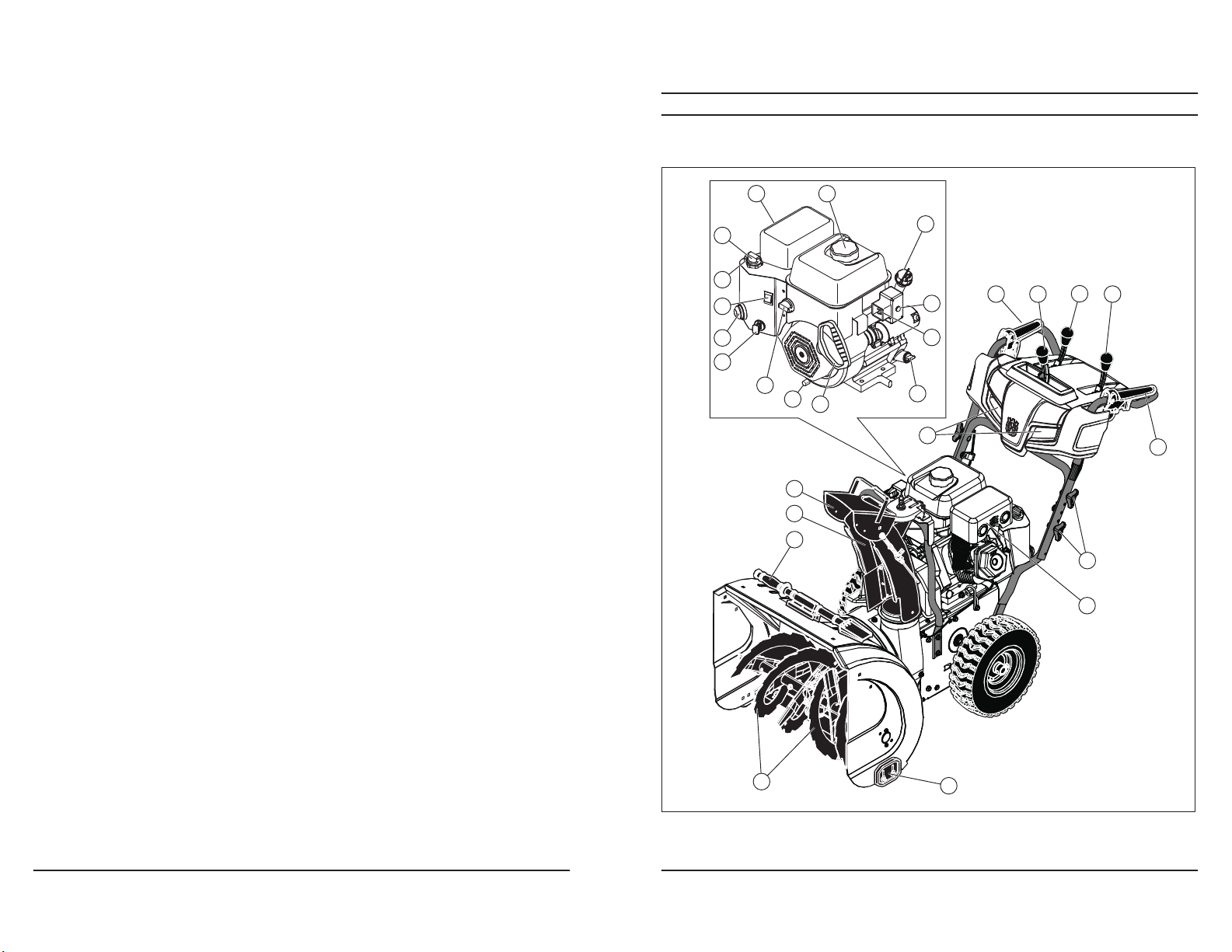
Product overview
3
78
I
21
20
19
18
17
8 22
16
15
14
13
12
11
26
23
24
25
6
1 2
3
4
5
7
8
10
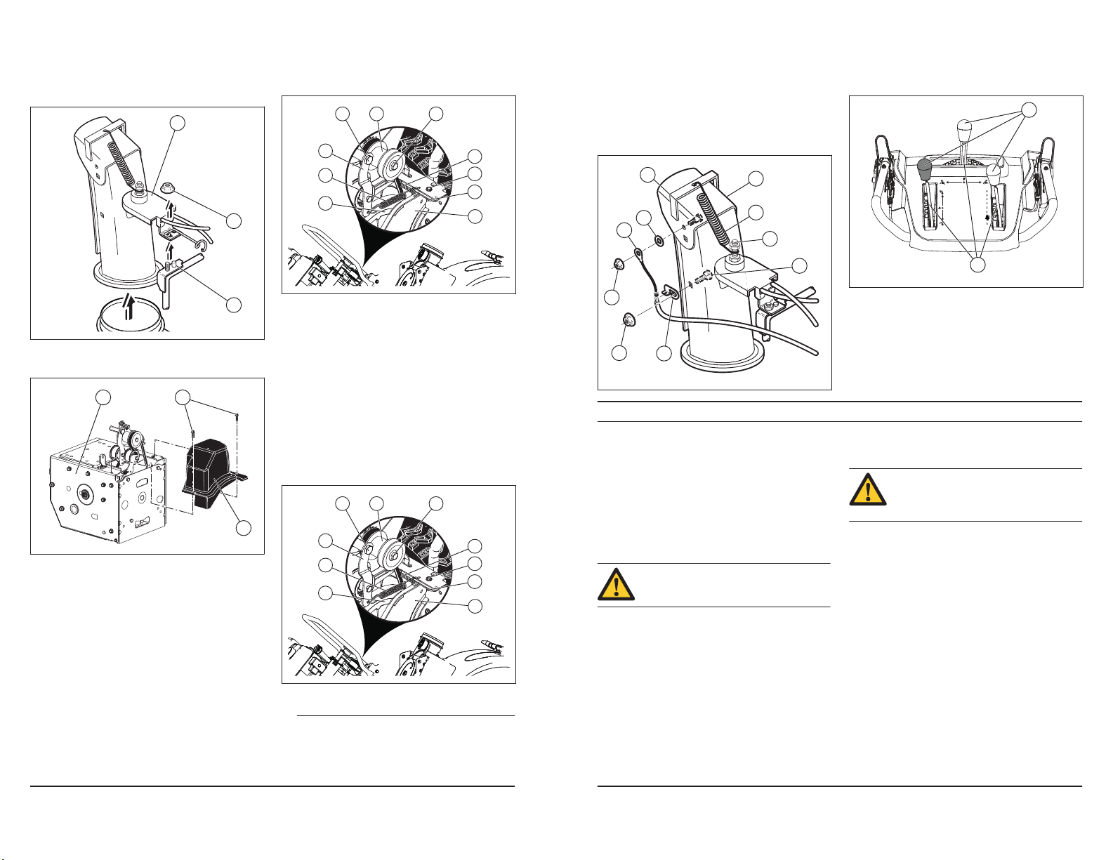
1. Auger engagement
2. Discharge chute control lever
7
694 - 002 -
694 - 002 -
9
3. Drive speed control lever
4. Deflector remote control lever
Transport, entreposage et mise au rebut
Transport et entreposage
Mise au rebut
Données techniques
Données techniques
Remarque :
ST 224 ST 227P ST 230P ST 224P
Dimensions
Moteur
Système électrique
77
5. Drive engagement
Product description
Intended use
Symbols on the product
Note
4
6. Light
7. Handle knob
8. Muffler
9. Skid plate
10. Augers
11. Clean-out tool
12. Discharge chute
13. Chute deflector
14. Starter rope handle
15. Oil drain plug
16. Fuel switch
17. ON/OFF key
18. Primer
19. ON/OFF switch
20. Throttle control
21. Choke
22. Gasoline filler cap
23. Oil fill (ST 227P, ST 230P), Dipstick (ST 227P)
24. Electric start button
25. Connection, electric start
26. Oil fill (ST 224, ST 224P), Dipstick (ST 224, ST
230P, ST 224P)
P
The product is a wheeled snow thrower that is used to
remove snow from the ground.
This product can be used to remove snow from fields,
roads, walkways and driveways. Do not use it on slopes
that are greater than 20°. Do not use the product in
areas where there is much debris, dirt and protruding
stones.
If the decals on the product are damaged, contact
the distributor to replace them.
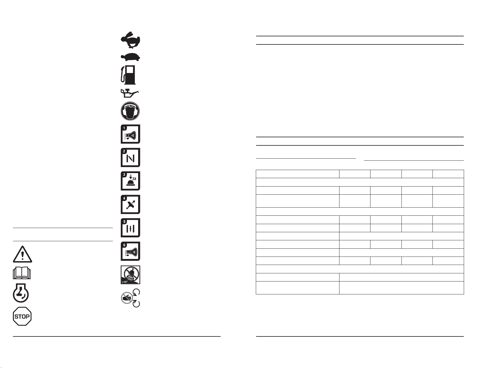
Warning.
Fast.
Slow.
Fuel.
Oil.
Ear protection recommended.
ON/OFF key. Insert to start and run.
Choke closed (start).
Primer.
Pull starter rope handle to start.
Choke open (run).
ON/OFF key. Pull out to stop.
T
• Conserver le produit dans un endroit sec à l’abri du
• Pour le stockage et le transport du produit et du
carburant, s’assurer qu’il n’y a pas de fuite ou de
vapeur. Les étincelles ou les flammes nues, par
exemple avec des appareils électriques ou des
chaudières, peuvent démarrer un incendie.
• Utiliser toujours des contenants agréés pour
entreposer ou transporter le carburant.
• Vider le réservoir de carburant avant de ranger le
produit pour une période prolongée. Mettre au rebut
le carburant à un emplacement de mise au rebut
adéquat
• Immobiliser le produit en sécurité pendant le
transport pour éviter tout dommage ou accident.
• Garder le produit dans un endroit verrouillé hors de
portée des enfants et des personnes non autorisées.
spécifications sont représentatives et pour référence
Poids, lb / kg 198,6 / 90 212 / 96 237,8 / 108 198,6 / 90
Pression d’utilisation maximale des pneus,
lb/po2
Marque et modèle
Cylindrée (cc) 208 254 291 208
Type de carburant Régulier sans-plomb (maximum 10 % d’éthanol)
Capacité du réservoir de carburant (gal / l) 0,31 / 1,17 0,35 / 1,33 0,62/2,35 0,31 / 1,17
Huile SAE 5W-30 (en dessous de 0 °C / 32 °F)
Capacité du réservoir d’huile (oz / l) 16 / 0,47 20 / 0,59 32 / 0,95 16 / 0,47
Toutes les données, les images et les
18 18 20 18
Husqvarna Husqvarna Husqvarna Husqvarna
gel.
• Respecter les exigences locales en matière de
recyclage et la réglementation en vigueur.
• Mettre au rebut tous les produits chimiques, tel que
le moteur d’huile ou de carburant, dans un centre de
service ou à un emplacement de mise au rebut
adéquat.
• Lorsqu’on n’utilise plus le produit, l’envoyer à un
détaillant Husqvarna ou le mettre au rebut à un
emplacement de recyclage.
uniquement, et elles peuvent être modifiées sans
préavis en raison d'améliorations apportées au produit.
Read the operator's manual.
Engine on
Engine off.
No operation on slopes more than 10
degrees.
Do not remove shields while engine is
running.
694 - 002 -
Bougie d’allumage F6RTC
Écartement des électrodes des bougies
(po / mm)
694 - 002 -
0,030 / 0 762 mm
Product liability
Safety
Safety definitions
WARNING
CAUTION
Note
5
P
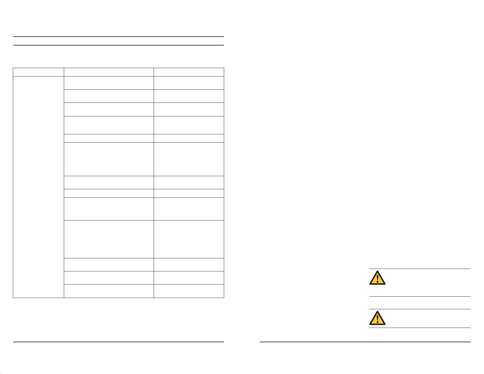
Problème Cause possible Solution
76
Perte de traction/ralentissement de la vitesse
d’entraînement
Perte de décharge ou ralentissement de la décharge de neige
Échec de rotation de la
tarière après le relâchement de la poignée
L’éclairage n’est pas
aligné (selon l’équipement)
Le rotateur de goulotte est
difficile à déplacer
Le produit tourne d’un
seul côté
La courroie glisse. Régler le câble. Régler la courroie.
La courroie est usée. Vérifier/remplacer la courroie. Régler
La courroie est sortie de la poulie. Vérifier/réinstaller la courroie. Régler
Le déflecteur de goulotte est obstrué. Nettoyer le déflecteur de goulotte.
Des corps étrangers obstruent les tarières. Retirer les débris ou le corps étrang-
La goupille de tonte est brisée. Remplacer la goupille de tonte bri-
Accumulation excessive de neige et de glace
entre les composants de la chenille.
La roue d’entraînement de friction est usée. Communiquer avec un centre de rép-
Le disque de friction est humide Laisser le disque de friction sécher
La courroie d’entraînement n’est pas alignée. Régler la courroie d’entraînement.
Le déflecteur d’éjection n’est pas aligné. Régler le déflecteur d’éjection.
Le moteur ne tourne pas. Démarrer le moteur.
Le branchement du câble est desserré. Vérifier les branchements électriques
La DEL est brûlée. Remplacer le module d’éclairage à
Il y a des débris dans le mécanisme du rotateur
de goulotte.
Câbles déformés ou endommagés. S’assurer que les câbles ne sont pas
La pression des pneus n’est pas égale. Régler la pression des pneus et gon-
Le produit est entraîné par une seule roue. Inspecter la goupille de blocage des
Réglage irrégulier du traîneau. Régler les plaques de protection et le
Réglage irrégulier des plaques de protection. Régler les plaques de protection et le
la poulie.
la poulie.
er des tarières.
sée.
Retirer la neige et la glace entre les
composants de la chenille.
aration agréé.
au niveau du moteur et des feux.
DEL. Il n’est pas possible de remplacer des DEL distinctes.
Nettoyer la partie interne du mécanisme du rotateur de réception.
endommagés. Remplacer les câbles
endommagés.
fler le pneu.
pneus.
traîneau.
traîneau.
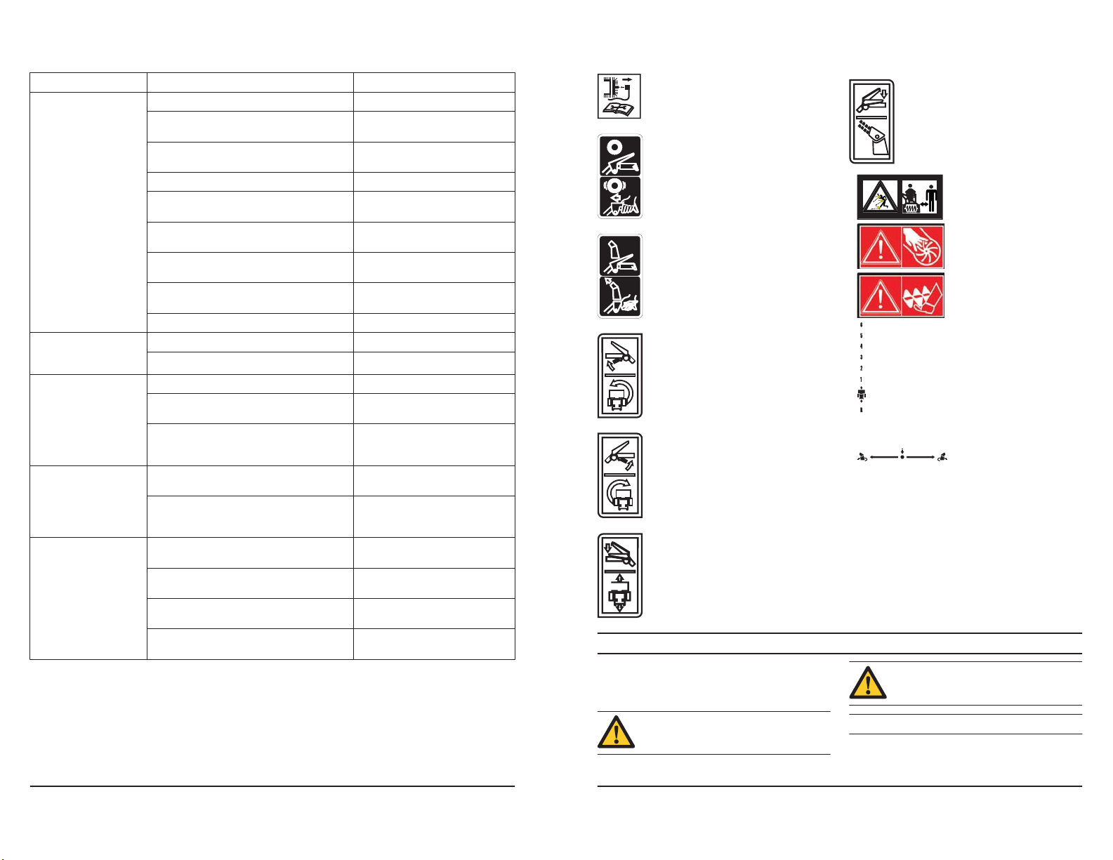
Remove spark plug cable before
maintenance.
Traction drive off/on.
Snow discharge off/on.
Steer left.
Steer right.
Traction drive control.
Snow discharge.
Beware of thrown objectskeep bystanders away.
Warning, keep hands
away.
Warning, keep feet away.
Forward/reverse.
Rotate left/push down/
rotate right.
As referred to in the product liability laws, we are not
liable for damages that our product causes if:
• the product is incorrectly repaired.
• the product is repaired with parts that are not from
the manufacturer or not approved by the
manufacturer.
• the product has an accessory that is not from the
manufacturer or not approved by the manufacturer.
• the product is not repaired at an approved service
center or by an approved authority.
694 - 002 -
The definitions below give the level of severity for each
signal word.
This information makes the product easier to use.
Injury to persons.
694 - 002 -
Damage to the product.

Problème Cause possible Solution
75
G
General safety instructions
Safety instructions for operation
6
• Use the product correctly. Injury or death is a
possible result of incorrect use. Only use the product
• Obey the instructions in this manual. Obey the safety
• Do not discard this manual. Use the instructions to
• Do not use a damaged product. Obey the
• This manual cannot include all situations that can
• Disconnect the spark plug cable before you
• Do not use the product if it is changed from its initial
• Do not breathe in the fumes from the engine. Long
• Do not start the product indoors or near flammable
• When you use this product the engine makes an
• Do not let a child operate the product. Do not let a
• Make sure that you always monitor a person, with
• Lock the product in an area that children and
for the tasks found in this manual. Do not use the
product for other tasks.
symbols and the safety instructions. If the operator
does not obey the instructions and the symbols,
injury, damage or death is a possible result.
assemble, to operate and to keep your product in
good condition. Use the instructions for correct
installation of attachments and accessories. Only
use approved attachments and accessories.
maintenance schedule. Only do the maintenance
work that you find an instruction about in this
manual. An approved service center must do all
other maintenance work.
occur when you use the product. Be careful and use
your common sense. Do not operate the product or
do maintenance to the product if you are not sure
about of the situation. Speak to a product expert,
your dealer, service agent or approved service
center for information.
assemble the product, put the product into storage or
do maintenance.
specification. Do not change a part of the product
without approval from the manufacturer. Only use
parts that are approved by the manufacturer. Injury
or death is a possible result of incorrect
maintenance.
term inhalation of the engine's exhaust fumes is a
health risk.
material. The exhaust fumes are hot and can contain
a spark which can start a fire. Not sufficient airflow
can cause injury or death because of asphyxiation or
carbon monoxide.
electromagnetic field. The electromagnetic field can
cause damage to medical implants. Speak to your
physician and medical implant manufacturer before
you operate the product.
person, without knowledge of the instructions
operate the product.
decreased physical capacity or mental capacity, that
uses the product. A responsible adult must be there
at all times.
unapproved persons cannot access.
• The product can eject objects and cause injuries.
Obey the safety instructions to decrease the risk of
injury or death.
• Do not go away from the product when the engine is
on.
• The operator of the product is responsible if an
accident occurs.
• Before and while you walk rearward, look behind and
down for small children, animals or other risks that
can cause you to fall.
• Make sure that parts are not damaged before you
use the product.
• Make sure that you are at a minimum 15 m (50 ft)
away from other persons or animals before you use
the product. Make sure that a person in adjacent
area knows that you will use the product.
• Refer to national or local laws. They can prevent or
decrease the operation of the product in some
conditions.
• Do not put hands or feet near or under rotating parts.
Keep clear of the discharge opening at all times.
• Exercise extreme caution when operating on or
crossing gravel drives, walks, or roads. Stay alert for
hidden hazards or traffic.
• After striking a foreign object, stop the engine
(motor), remove the wire from the spark plug,
disconnect the cord on electric motors, thoroughly
inspect the product for any damage, and repair the
damage before restarting and operating the product.
• If the product starts to vibrate abnormally, stop the
engine (motor) and check immediately for the cause.
Vibration is generally a warning of trouble.
• Stop the engine (motor) whenever you leave the
operating position, before unclogging the auger
housing or chute deflector, and when making any
repairs, adjustments or inspections.
• When cleaning, repairing or inspecting the product,
stop the engine and make certain the augers and all
moving parts have stopped. Disconnect the spark
plug wire and keep the wire away from the plug to
prevent someone from accidentally starting the
engine.
• Do not run the engine indoors, except when starting
the engine and for transporting the product in or out
of the building. Open the outside doors; exhaust
fumes are dangerous.
• Exercise extreme caution when operating on slopes.
• Never operate the product without proper guards,
and other safety protective devices in place and
working.
• Never direct the chute deflector toward people or
areas where property damage can occur. Keep
children and others away.
• Do not overload the product capacity by attempting
to clear snow at too fast a rate.
P
Puissance réduite Le fil de la bougie d’allumage n’est pas con-
Le moteur tourne au ralenti ou ronfle
Vibrations/Mouvements
excessifs de la poignée
La poignée du lanceur est
difficile à tirer
necté.
Le produit rejette trop de neige. Réduire la vitesse et la largeur de
Le couvercle du réservoir de carburant est recouvert de glace ou de neige.
Le silencieux est sale ou bouché. Nettoyer ou remplacer le silencieux.
Mauvaise longueur de câble. Régler le câble.
Le silencieux est obstrué. Vérifier que le moteur est froid. Retir-
La prise d’air d’admission du carburateur est obstruée.
Le volet de départ est à la position ON (marche,
complètement ouvert).
La conduite de carburant est obstruée. Nettoyer la conduite de carburant.
Il y a de l’eau dans le carburant ou le carburant
est trop vieux.
Le carburateur doit être remplacé. Communiquer avec un centre de rép-
La courroie est tendue. Remplacer la courroie trapézoïdale
Certaines pièces sont desserrées. Les tarières
sont endommagées.
Les poignées ne sont pas correctement positionnées.
Les écrous du levier de réglage sont desserrés. Serrer les écrous jusqu’à ce que la
La poignée du lanceur est gelée. Tirer autant que possible sur corde
La corde interfère avec les composants. La corde du lanceur ne doit toucher
Connecter le fil à la bougie d’allumage.
l’andain.
Retirer la glace et la neige sur et autour du couvercle du réservoir de carburant.
er l’obstruction.
Vérifier que le moteur est froid. Retirer l’obstruction.
Déplacer le volet de départ à la position OFF (arrêt, fermé).
Vider le réservoir de carburant et le
carburateur. Remplir le réservoir de
carburant avec de l’essence fraîche
et propre.
aration agréé.
de la tarière.
Serrer tout le matériel de fixation. Remplacer les pièces endommagées. Si
la vibration persiste, communiquer
avec un centre de service agréé.
Assurez-vous que les poignées sont
verrouillées en position.
poignée soit sécuritaire.
du lanceur, puis relâcher la poignée.
Si le moteur ne démarre pas, répéter
la procédure ou utiliser le démarreur
électrique.
aucun câble ni tuyau.
694 - 002 -
694 - 002 -
Work area safety
Personal protective equipment
Safety devices on the product
Muffler
CAUTION
Fuel safety
WARNING
7
D
Dépannage
Dépannage
Problème Cause possible Solution
74
L’outil ne démarre pas La clé de démarrage de sécurité n’est pas insér-
ée.
Le produit est en panne de carburant. Remplir le réservoir de carburant
La clé ON/OFF (marche/arrêt) est à la position
OFF (arrêt).
Le volet de départ est à la position OFF (arrêt,
fermé).
L’amorceur n’est pas enfoncé. Appuyer sur l’amorceur.
Le moteur est noyé. Attendre quelques minutes avant de
Le fil de la bougie d’allumage n’est pas connecté.
La bougie d’allumage est défectueuse. Remplacer la bougie d’allumage.
Il y a de l’eau dans le carburant ou le carburant
est trop vieux.
Il y a de la vapeur dans la conduite de carburant.
Autres causes. Lire attentivement les méthodes de
Le commutateur de carburant (selon l’équipement) est à la position CLOSE (arrêt).
La commande d’accélération est à la position
STOP (Arrêt).
Insérer la clé de démarrage de sécurité.
avec de l’essence fraîche et propre.
Placer la clé ON/OFF (marche/arrêt)
à la position ON (marche).
Déplacer le volet de départ à la position ON (marche, complètement ouvert).
redémarrer, NE PAS purger.
Redémarrer le moteur à plein régime
avec le volet de départ à la position
OFF (arrêt, fermé).
Connecter le fil à la bougie d’allumage.
Vider le réservoir de carburant et le
carburateur. Remplir le réservoir de
carburant avec de l’essence fraîche
et propre.
S’assurer que toute la conduite d’alimentation en carburant est en dessous de la sortie du réservoir de carburant. La conduite d’alimentation en
carburant doit fonctionner en permanence entre le réservoir de carburant
et le carburateur.
démarrage de ce manuel.
Placer le commutateur de démarrage
du moteur à la position ON (marche).
Déplacer la commande d’accélérateur à la position FAST (Rapide).
• Never operate the product at high transport speeds
on slippery surfaces. Look behind and use care
when operating in reverse.
• Disengage power to the augers when the product is
transported or not in use.
• Use only attachments and accessories approved by
the manufacturer of the product (such as wheel
weights, counterweights, or cabs).
• Never operate the product without good visibility or
light. Always be sure of your footing, and keep a firm
hold on the handles. Walk; never run.
• Never touch a hot engine or muffler.
W
• Thoroughly inspect the area where the equipment is
to be used and remove all doormats, sleds, boards,
wires, and other foreign objects.
• Disengage all clutches and shift into neutral before
starting the engine (motor).
• Do not operate the product without wearing
adequate winter garments. Avoid loose fitting
clothing that can get caught in moving parts. Wear
footwear that will improve footing on slippery
surfaces.
• Handle fuel with care; it is highly flammable.
• Use an approved fuel container.
• Never add fuel to a running engine or hot engine.
• Fill fuel tank outdoors with extreme care. Never
fill fuel tank indoors.
• Never fill containers inside a vehicle or on a truck
or trailer bed with a plastic liner. Always place
containers on the ground, away from your
vehicle, before filling.
• When practical, remove gas-powered equipment
from the truck or trailer and refuel it on the
ground. If this is not possible, then refuel such
equipment on a trailer with a portable container,
rather than from a gasoline dispenser nozzle.
• Keep the nozzle in contact with the rim of the fuel
tank or container opening at all times, until
refueling is complete. Do not use a nozzle lockopen device.
• Replace gasoline cap securely and wipe up
spilled fuel.
• If fuel is spilled on clothing, change clothing
immediately.
• Use extension cords and receptacles as specified by
the manufacturer for all units with electric drive
motors or electric starting motors.
• Adjust the auger housing height to clear gravel or
crushed rock surface.
• Never attempt to make any adjustments while the
engine (motor) is running (except when specifically
recommended by the manufacturer).
• Always wear safety glasses or eye shields during
operation or while performing an adjustment or
repair to protect eyes from foreign objects that may
be thrown from the machine.
Always use the correct personal protective equipment
when you operate the product. This includes, at
minimum, sturdy footwear, eye protection and hearing
protection. Personal protective equipment does not
erase the risk of injury but may decrease the grade of
injury if an accident occurs.
• Always wear safety glasses or eye protection while
you operate the product or do maintenance or
repairs.
• Always wear appropriate winter garments when you
operate the product.
• Always use heavy-duty slip-resistant boots with good
ankle support while you operate the product.
• Do not wear loose fitting clothing that can get caught
in moving parts.
• Use approved protective gloves, if necessary. For
example, when attaching, examining or cleaning the
blade.
• Always use approved ear protection while you
operate the product. Noise for a long period can
cause noise-induced hearing loss.
• Make sure that you regularly do the maintenance to
the product.
• The life of the product increases.
• The risk of accidents decreases.
Let an approved dealer or an approved service
center regularly examine the product to do
adjustments or repairs.
• Do not use a product with damaged protective
equipment. If the product is damaged, speak to an
approved service center.
The muffler keeps the noise levels to a minimum and
sends the exhaust fumes away from the operator.
Do not use the product if the muffler is missing or
defective. A defective muffler increases the noise level
and the risk of fire.
Examine the muffler regularly to make sure that it is
attached correctly and not damaged.
during and after use and when the engine
operates at idle speed. Be careful near
flammable materials and/or fumes to prevent
fire.
that follow before you use the product.
The muffler becomes very hot
Read the warning instructions
694 - 002 -
694 - 002 -
Pour nettoyer l’outil
73
• Do not start the product if there is fuel or engine oil
Proposition 65
Safety instructions for maintenance
WARNING
Assembly
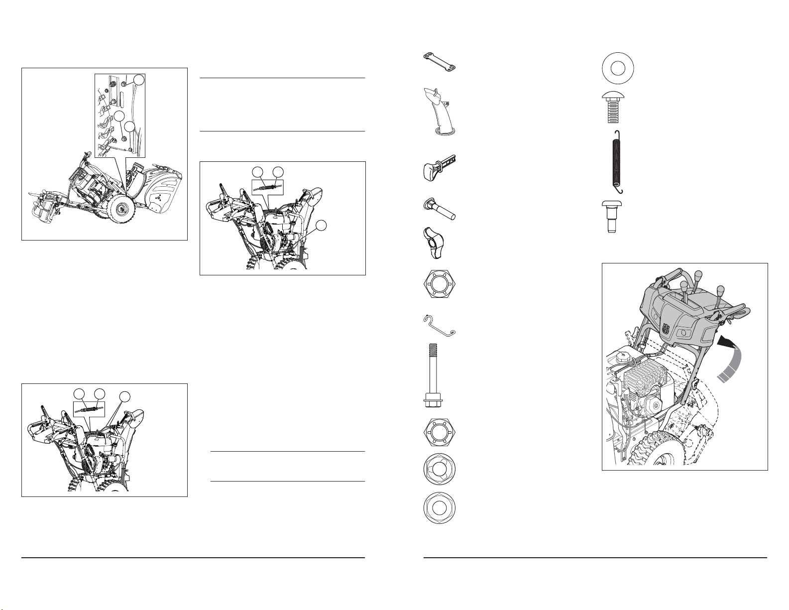
To remove the product from the carton
Loose parts
8
on the product. Remove the unwanted fuel/oil and let
the product dry.
• If you spill fuel on your clothing, change clothing
immediately.
• Do not get fuel on your body, it can cause injury. If
you get fuel on your body, use soap and water to
remove the fuel.
• Do not start the product if the engine has a leak.
Examine the engine for leaks regularly.
• Be careful with fuel. Fuel is flammable and the fumes
are explosive and can cause injuries or death.
• Do not breathe in the fuel fumes, it can cause injury.
Make sure that there is a sufficient airflow.
• Do not smoke near the fuel or the engine.
P
• Do not put warm objects near the fuel or the engine.
• Do not add the fuel when the engine is on.
• Make sure that the engine is cool before you refuel.
• Before you refuel, open the fuel tank cap slowly and
release the pressure carefully.
• Do not add fuel to the engine in an indoor area. Not
sufficient airflow can cause injury or death because
of asphyxiation or carbon monoxide.
• Tighten the fuel tank cap fully. If the fuel tank cap is
not tightened, there is a risk of fire.
• Move the product a minimum of 3 m (10 ft) from the
position where you filled the tank before a start.
• Do not put too much fuel in the fuel tank.
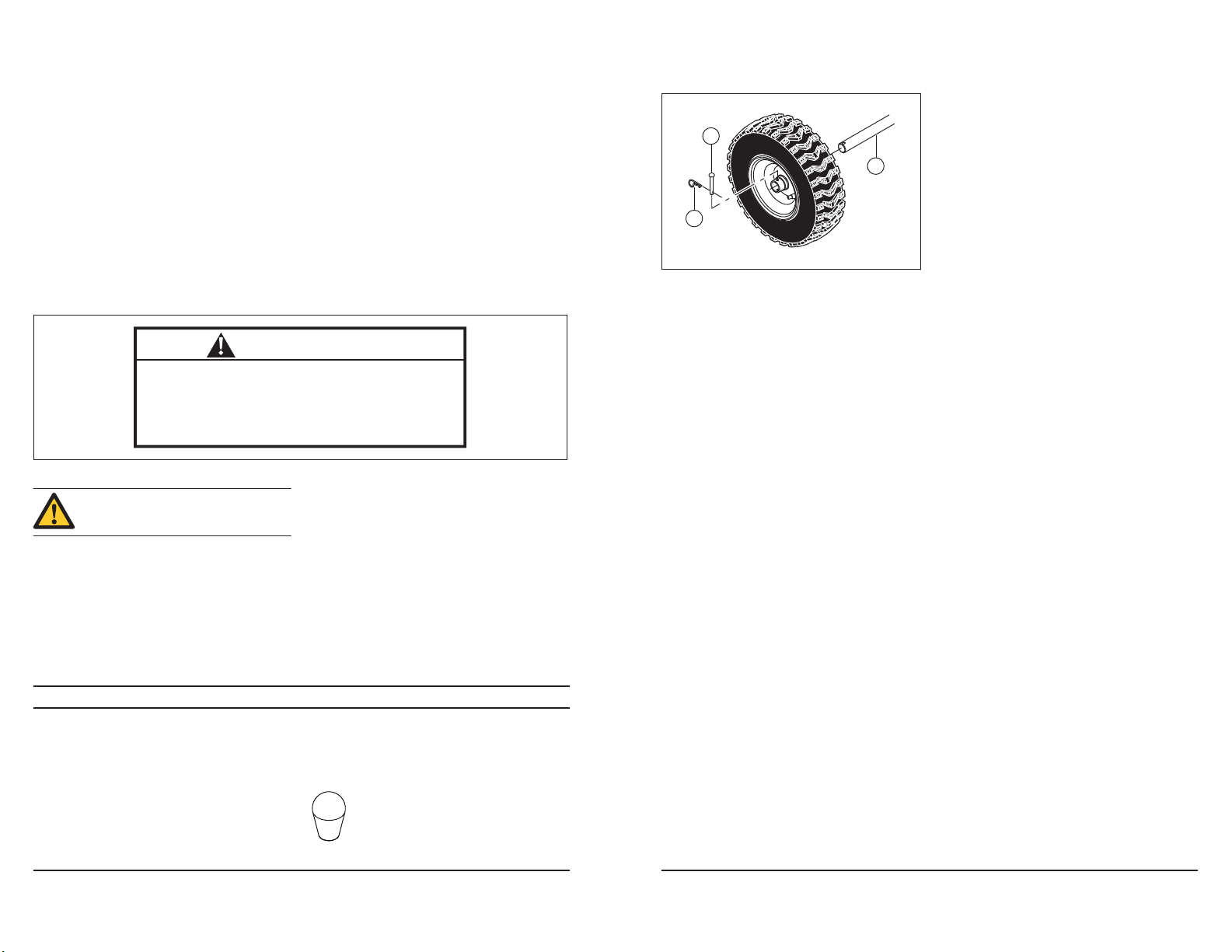
2. Enlever la roue de l’arbre (C).
A
B
• Nettoyer les pièces en plastique à l’aide d’un chiffon
propre et sec.
• Ne pas utiliser de nettoyeur à haute pression pour
nettoyer la tondeuse.
C
• Ne pas verser de l’eau directement sur le moteur.
• Utiliser une brosse pour enlever les feuilles, l’herbe
et la saleté.
WARNING
The engine exhaust from this product
contains chemicals known to the State of
California to cause cancer, birth defects
or other reproductive harm.
• The exhaust fumes from the engine contain carbon
• Before you do the maintenance on the product, stop
• Use protective gloves when you do maintenance on
1. Remove loose parts included with the product. Cut
2. Remove the two screws that attach the auger
3. Cut the cable ties that hold the product to the pallet
that follow before you use the product.
monoxide, an odorless, poisonous and very
dangerous gas. Do not start the engine indoors or in
closed spaces.
the engine and remove the ignition cable from the
spark plug.
the blades. The blades are very sharp and cuts can
easily occur.
the four corners of the carton and put the end panels
down flat.
housing to the pallet. Remove the steel brackets
from the skid plates if they have it.
and remove them.
Read the warning instructions
• Accessories and changes to the product that are not
approved by the manufacturer, can cause serious
injury or death. Do not change the product. Always
use accessories that are approved by the
manufacturer.
• If the maintenance is not done correctly and
regularly, the risk of injury and damage to the
product increases.
• Only do the maintenance as given in this operator's
manual. All other servicing must be done by an
approved service agent.
• Let an approved service agent do servicing on the
product regularly.
• Replace damaged, worn or broken parts.
4. Remove all package materials.
5. Remove the product from the carton and make sure
no loose parts are left in the carton.
Knob (3)
694 - 002 -
694 - 002 -
To install the handle
9
5. Installer les boulons de 5/16 po (A), (C) et les serrer
Réglage de la tension du câble du
déflecteur de la goulotte d’éjection
Ajustement du câble de commande de
la tarière
Remarque :
Remarque :
Dépose des roues
72
(8 à 12 lb/po2 / 11 à 16 Nm).
A
C
B
ce réglage vous-même, veuillez communiquer avec un
centre d’entretien autorisé. Si la rotation de la tarière est
ralentie lorsque le levier de commande est engagé ou si
la courroie a été remplacée, il est possible qu’un réglage
soit nécessaire.
1. Desserrer les écrous de blocage (B) à côté du
Si vous ne vous sentez pas à l’aise de faire
tendeur (A) pour régler la tension du câble de
commande de la tarière (D).
A B
D
Multi-wrench (1)
Nylon washer (1)
Carriage bolt 5/16-18 x 5/8 (1)
Discharge chute (1)
ON/OFF key (s)
Spring (1)
Carriage bolts 5/16-18 x 2 ¼” (2)
Shoulder bolt ¼-20 (1)
6. Installer les boulons de ¼ po (B) et les serrer (4 à
6 lb/po2 / 5 à 8 Nm).
7. Installer la courroie de la tarière sur la poulie du
moteur. S’assurer que la courroie est correctement
placée sur la poulie folle et correctement installée
dans la rainure de la poulie du moteur.
8. Actionner toutes les commandes afin de s’assurer
que la courroie de la tarière est correctement
installée et que tous les composants se déplacent
correctement.
1. Desserrer les écrous de blocage (B) afin de régler la
tension du câble de la goulotte d’éjection adjacente
au dispositif de réglage du tendeur (A).
A B
2. Tenir fermement la section courte et tourner la
section longue afin d’allonger le tendeur.
3. Procéder à un ajustement jusqu’à ce que le câble du
déflecteur de la goulotte d’éjection (C) soit bien
serré. Serrer les écrous de blocage.
C
2. Tenir la section courte et faire tourner la section
longue. La tourner sur 360 degrés.
3. Vérifier l’engagement de la tarière. Répéter le
réglage jusqu’à ce qu’il ne reste qu’une faible
tension dans le câble lorsque le levier est
désengagé.
4. Serrer l’écrou de blocage inférieur afin de le
verrouiller en tension.
5. Demander à un assistant de se tenir à 3 mètres /
10 pieds devant le produit, sur le côté opposé de la
goulotte. L’assistant doit observer la rotation de la
tarière et calculer le temps nécessaire pour l’arrêt de
la rotation après avoir relâché le levier. Si la tarière
cesse de tourner après 5 secondes, régler la
longueur du câble en faisant tourner le cylindre
central sur 360 degrés pour rétracter le dispositif de
réglage. Vérifier la tarière et calculer le temps à
nouveau. Si la tarière cesse de tourner en moins de
5 secondes, passer à l’étape suivante.
6. Serrer le contre-écrou sur le câble de la tarière.
problème, remplacer la courroie de la tarière. Voir
Retrait de la courroie de tarière à la page 71
1. Déposer l’axe de la roue (A) et l’axe de retenue (B).
Si le réglage du câble ne règle pas le
.
Handle knobs (2)
Locknut 3/8 (1)
Cable guide (1)
Shear pins ¼-20 x 1-¾ (6)
Locknuts ¼-20 (6)
Locknut 5/16-18 (1)
Locknut ¼-20 (1)
1. Raise the upper handle to the operating position.
694 - 002 -
694 - 002 -
Installation du carter de la courroie
Retrait de la courroie de tarière
Installation de la courroie de tarière
MISE EN GARDE :
71
2. Adjust the handle position to one of the mounting
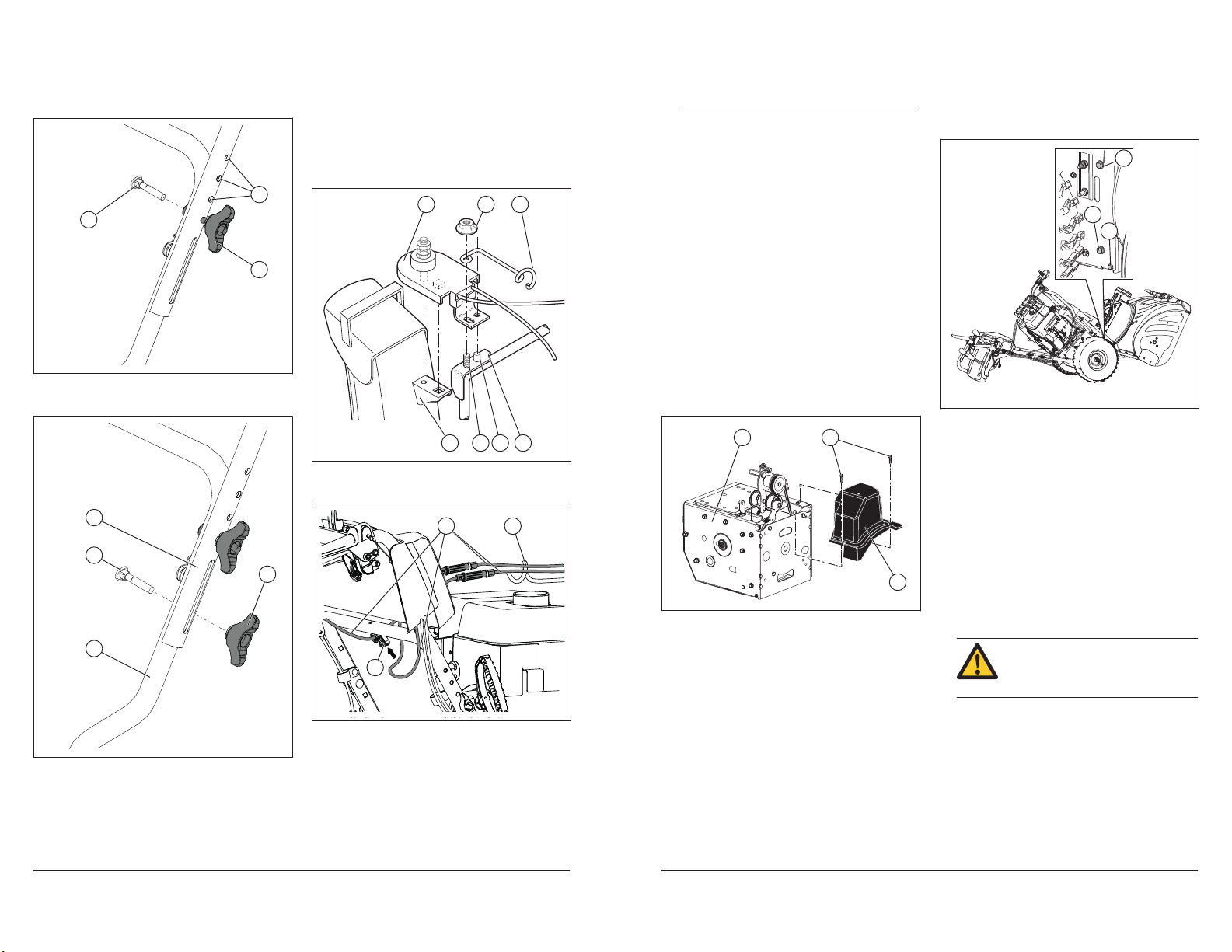
To install the chute deflector and chute
rotator head
To install the chute deflector remote
control
10
holes (B) and tighten the handle knobs (C) with the
carriage bolts (D).
B
D
C
3. Install more carriage bolts (D) and handle knobs (C)
to secure the upper handle (A) to the lower handle
(E).
A
D
C
E
1. Put the chute deflector assembly on the top of the
chute base with the discharge opening in the
direction of the front of the product.
2. Put the chute rotator head (A) on the chute bracket
(B). Rotate the chute assembly to align the pins
under the chute rotator head with the holes in the
chute bracket if it is necessary.
3. Put the chute rotator head on the pin (C) and the
threaded stud (D) on the mounting bracket (E).
4. Attach a locknut (G) on the threaded stud and
tighten.
A
FG
B CDE
5. Put the cables through the cable guide (F) and the
double clip (I) to attach the rotator cable (H) to the
lower handle.
H
F
I
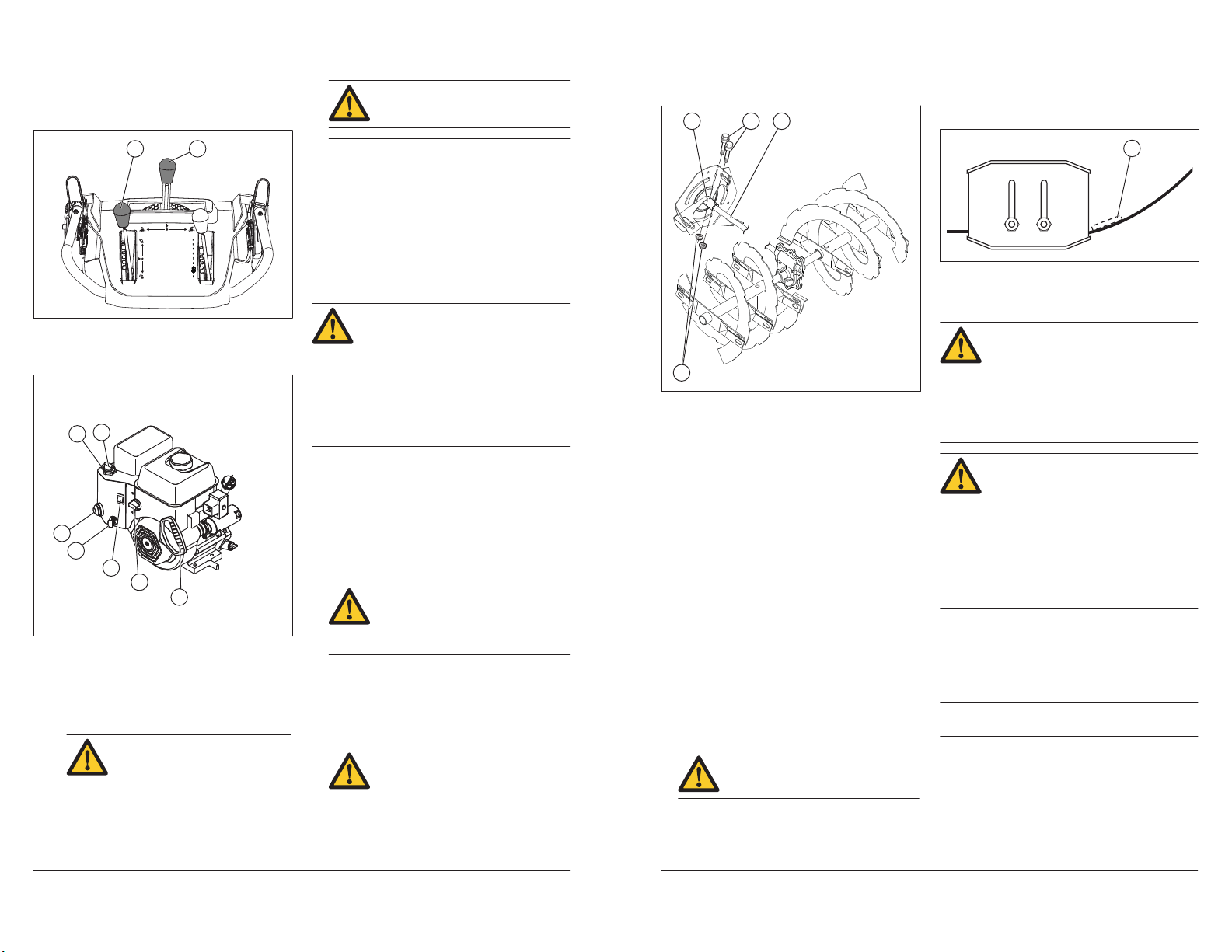
1. Attach the remote cable bracket (A) to the discharge
chute with a carriage bolt (B) and a 5/16-18 locknut
(D). Tighten the bolt.
rainure de la poulie d’entraînement avant d’abaisser
le plateau de rotation.
3. Installer et serrer le boulon supérieur (I).
4. Placer la courroie d’entraînement dans la rainure de
la poulie du moteur (G) avant de l’installer sur l’arbre
du moteur.
5. Installer le boulon de la poulie (F) et l’attacher la
poulie du moteur sur le moteur. Serrer le boulon de
la poulie (de 30 à 35 pi- lb / de 41 à 47 Nm).
6. Installer le levier du tendeur de courroie
d’entraînement (B) et serrer le boulon du levier (E)
sur le moteur.
7. Installer le ressort de rappel (C) sur le plateau de
rotation.
8. Installer le ressort du tendeur (A) sur le levier du
tendeur.
9. Actionner toutes les commandes pour s’assurer que
la courroie d’entraînement est correctement installée
et que tous les composants se déplacent
correctement.
I
1. Installer le carter de la courroie (B) sur le châssis (C)
et serrer les deux vis (A).
C A
B
2. Installer la goulotte de décharge.
1. Retirer les boulons 5/16 po (A) et les boulons ¼ po
inférieurs (B) des 2 côtés du châssis. Conserver les
boulons.
A
C
B
2. Desserrer, sans retirer, les boulons de 5/16 po
inférieurs (C) des 2 côtés du châssis.
3. Retirer la courroie de tarière de la poulie du moteur.
4. Incliner la partie arrière vers le bas. La partie avant
s’incline vers l’avant par la même occasion. Le
boulon inférieur (C) sert de charnière entre les
sections avant et arrière.
5. Placer une cale en bois sous le point de charnière
afin de mettre le produit en position repliée.
6. Déplacer le levier du tendeur de courroie de la
tarière et retirer la courroie de la tarière du levier.
1. Déplacer le levier du tendeur de courroie et placer la
courroie de tarière dans la rainure de la poulie de
tarière.
courroie n’est pas coincée entre le
châssis et le carter de la tarière lorsque
vous assemblez l’unité.
2. Retirer le bloc de bois à partir de la partie inférieure
du produit.
3. Tourner la poignée pour incliner la partie arrière vers
le haut. La partie avant s’inclinera vers l’arrière et
pivotera afin de fixer la partie arrière.
4. S’assurer que la courroie est correctement
positionnée dans la rainure de la poulie de tarière.
S’assurer que la
694 - 002 -
694 - 002 -
Operation
Before you start the product
To fill the engine with oil
CAUTION
To fill fuel
CAUTION
To adjust the discharge chute and the
chute deflector
11
2. Desserrer le contre-écrou (A) qui fixe la tête du
Retrait de la courroie d’entraînement
Installation de la courroie d’entraînement
Remarque :
70
rotateur de goulotte (B) au support de montage (C)
afin de retirer la goulotte d’éjection.
B
2. Déposer le ressort du tendeur (A) fixé sur le levier du
tendeur de courroie d’entraînement (B).
E
B
A
FG
H
I
2. Install the remote cable eyelet (E) to the chute
deflector (F) with a shoulder bolt (G), a nylon washer
(C), and tighten with a ¼-20 locknut (K). The cable
eyelet will be loose on the shoulder bolt.
3. Attach the spring (L) between the hex nut (M) on the
chute rotator head and the hole on the chute
deflector.
G
F
4. Attach the lever control knobs (N) by pressing them
down on the control levers (O).
N
C
J
A
D
C
E
L
M
C
3. Desserrer les deux vis (A) qui maintiennent le carter
de la courroie (B) sur le châssis (C) et enlever le
carter de la courroie.
C A
B
1. Retirer la courroie de tarière. Voir
courroie de tarière à la page 71
Retrait de la
.
3. Déposer le ressort de rappel (C) qui maintient le
plateau de rotation (D) en place.
4. Déposer le boulon du levier (E) et le levier du
tendeur de courroie.
5. Retirer le boulon de la poulie (F), la poulie du moteur
(G) et la courroie d’entraînement (H) du moteur.
6. Retirer le boulon supérieur (I) qui maintient le
plateau de rotation sur le châssis
7. Pivoter et maintenir le plateau de rotation à l’écart du
produit et retirer la courroie d’entraînement de la
poulie d’entraînement (J).
1. Pivoter et maintenir le plateau de rotation (D) à
l’écart du produit.
E
B
A
J
2. Placer la courroie d’entraînement (H) sur la poulie
d’entraînement (J).
d’entraînement est acheminée correctement dans la
S’assurer que la courroie
FG
B
O
K
D
• Keep persons and animals away from the work area.
• Do daily maintenance. See
on page 15
• Make sure the ignition lead fits correctly on the spark
plug.
• Add oil or gasoline, if necessary. See
on page 25
H
I
C
D
1. Remove the oil cap and clean the dipstick. See
Product overview on page 3
dipstick.
2. Add oil to the top mark on the dipstick. Use the
dipstick to do a check of the oil level at regular
intervals.
3. Put the oil cap back.
If available, use low-emission/alkylate gasoline. If lowemission/alkylate gasoline is not available, use good
quality unleaded gasoline or leaded gasoline. Use
A
.
.
you check the oil. Do not fill above the mark.
Maintenance schedule
Technical data
Do not rotate the dipstick when
for the location of the
gasoline with an octane number of 90 RON out of North
America (87 AKI in North America) or higher, and with a
maximum of 10% ethanol (E10).
octane number less than 90 RON out of
North America (87 AKI in North America).
This can cause damage to the product.
1. Open the fuel tank cap slowly to release the
pressure.
2. Fill slowly with a fuel can. If you spill fuel, remove it
with a cloth and let remaining fuel dry off.
3. Clean the area around the fuel tank cap.
4. Tighten the fuel tank cap fully. If the fuel tank cap is
not tightened, there is a risk of fire.
5. Move the product a minimum of 3 m (10 ft) from the
position where you filled the tank, before a start.
1. To adjust the discharge chute position, move the
discharge chute control lever (A) back and to the left
or right direction.
Do not use gasoline with an
694 - 002 -
694 - 002 -
Pour examiner les pneus
Dégagement d’un déflecteur de
goulotte bouché
AVERTISSEMENT :
Remplacement de la barre de racleur
Courroies d’entraînement
AVERTISSEMENT :
AVERTISSEMENT :
Remarque :
Remarque :
Préparation du remplacement des courroies
69
2. To adjust the snow throwing distance of the chute
To start the engine, manual start
CAUTION
CAUTION
Note
To start the engine, electric start
WARNING
CAUTION
CAUTION
12
deflector, move the deflector remote control lever (B)
down to decrease the distance and up to increase
the distance.
AB
quickly. Move it back to the start position
much rope out of the starter as possible and release
the starter rope handle. If the engine does not start,
repeat the procedure or use the electric starter.
6. If the choke was used to start the engine, slowly
move the choke (D) to the OFF position.
7. Run the engine 2-3 minutes at idling speed before
you start to throw snow.
8. If the engine does not run as it should, turn it off.
slowly.
If the rope starter has frozen, slowly pull out as
Do not release the grip
4. Installer un contre-écrou ¼-20 (D) sur la goupille de
tonte et serrer.
A C B
1. Placer la barre de racleur (A) dans la position
inversée lorsqu’elle est usée du côté du carter.
A
2. Remplacer la barre de racleur si elle est usée des
deux côtés ou si elle est endommagée.
1. Insert the ON/OFF key (A) into the ignition slot until it
clicks. Do not turn the key.
D
B
E
A
C
F
G
2. Turn the fuel ON/OFF switch (F) to the ON position.
3. Put the throttle control (B) to the FAST position.
4. Put the ON/OFF switch (C) to the ON position.
a) If the engine is cold, rotate the choke (D) to the
FULL position and push the primer (E) three
times.
engine. It can prevent the engine
from starting. If the engine is over
primed, wait a few minutes before
attempting to start and do not push
the primer.
5. Pull the starter rope handle (G).
Do not over prime the
1. Insert the ON/OFF key (A) into the ignition slot until it
2. Turn the fuel ON/OFF switch (F) to the ON position.
3. Put the throttle control (B) to the FAST position.
4. Put the ON/OFF switch (C) to the ON position.
5. Push the primer (E) three times.
6. Connect the extension cord to the connector on the
7. Connect the other end of the extension cord into a
8. Push the electric start button (H) until the engine
electric starter. Do not use the electric
starter if your house is not a 120 V A.C.
three-wire grounded system. Serious
personal injury or damage to the product
could occur. The electric starter has a threewire power plug, and is designed to use 120
V A.C. household current. Make sure that
your house is a 120 V A.C. three-wire
grounded system. If you are uncertain, ask a
licensed electrician.
clicks. Do not turn the key.
a) If the engine is cold, turn the choke (D) to the
FULL position.
engine (G).
three-hole grounded 120 V A.C. receptacle.
starts.
The product has a 120 V A.C.
It can prevent the engine from starting. If
the engine is over primed, wait a few
minutes before trying to start and do not
push the primer.
than five continuous seconds between
each time you try to start. Wait 5 to 10
seconds between each try.
Do not over prime the engine.
Do not crank the engine more
D
5. Insérer la clé ON/OFF (marche/arrêt) dans le
contact, puis brancher le câble d’allumage de la
bougie.
• Maintenir les pneus exempts de carburant et d’huile
pour éviter d’endommager le caoutchouc.
• Maintenir les pneus à l’écart de souches, de pierres,
d’ornières, d’objets pointus et de tout autre objet
pouvant les endommager.
• Maintenir la pression correcte des pneus, voir
Données techniques à la page 77
Ne pas déboucher le déflecteur de goulotte avant de
réaliser les opérations suivantes.
1. Relâcher simultanément l’engagement de la tarière
et celui de l’entraînement.
2. Attendre 10 secondes pour s’assurer que les tarières
sont arrêtées.
3. Mettre le produit hors tension.
4. Utiliser l’outil de nettoyage (au moins 38 cm [15 po]
de long, inclus avec certains modèles) pour retirer
l’obstruction.
mains dans le déflecteur de goulotte ou
à l’intérieur du carter de tarière.
.
Ne pas placer les
spécialement conçues pour le produit et
doivent être remplacées par des pièces du
fabricant d’origine disponibles auprès de
votre centre de services le plus proche.
L’utilisation de courroies autres que celles
du fabricant d’origine peut causer des
blessures personnelles ou endommager le
produit.
courroie nécessite le démontage du produit.
Pour séparer le carter de la tarière du
châssis, il est important qu’un assistant se
tienne debout dans la position de
fonctionnement et qu’il tienne les poignées
du produit. Des blessures corporelles graves
ou un endommagement du produit
pourraient se produire si le produit est
échappé pendant le remplacement de la
courroie.
la tarière et la courroie d’entraînement. Remplacer les
courroies si elles sont endommagées ou si elles
commencent à glisser en raison de l’usure. Il est
recommandé de faire remplacer les courroies par un
centre de réparation agréé.
d’entraînement ainsi que la courroie de la tarière.
1. Retirer le carburant du réservoir de carburant.
Il n’est pas possible d’ajuster la courroie de
Il est recommandé de remplacer la courroie
Les courroies en V sont
Le remplacement de la
694 - 002 -
694 - 002 -
 Loading...