


96193002700
Table of contents
 Loading...
10527SB
10527SB
Owner's Manual / 96193992700
IMPORTANT
Safe Operation Practices for Walk-Behind Snow Throwers
This snow thrower is capable of amputating hands and feet and throwing objects.
Failure to observe the following safety instructions could result in serious injury.
Look for this symbol to point out im por tant safety precautions. It means
CAUTION!!! BE COME ALERT!!! YOUR
SAFE TY IS IN VOLVED.
WARNING: Always disconnect spark
plug wire and place it where it can not
con tact plug in order to pre vent ac ci den tal start ing when setting up, trans port ing, ad just ing or making re pairs.
WARNING: This snow thrower is for
use on sidewalks, driveways and other
ground level surfaces. Caution should
be exercised while using on sloping surfaces. Do not use snow thrower on
surfaces above ground level such as
roofs of residences, garages, porch es
or other such structures or buildings.
Training
1. Read, understand and follow all instructions on the
machine and in the manual(s) before operating this
unit. Be thoroughly familiar with the controls and the
proper use of the equipment. Know how to stop the
unit and disengage the controls quickly.
2. Never allow children to operate the equipment. Never
allow adults to operate the equipment without proper
instruction.
3. Keep the area of operation clear of all persons, particularly small children.
4. Exercise caution to avoid slipping or falling, especially
when operating the snow thrower in reverse.
Preparation
1. Thoroughly inspect the area where the equipment is
to be used and remove all doormats, sleds, boards,
wires, and other foreign objects.
2. Disengage all clutches and shift into neutral before
starting the engine (motor).
3. Do not operate the equipment without wearing adequate
winter garments. Avoid loose fitting clothing that can
get caught in moving parts. Wear footwear that will
improve footing on slippery surfaces.
4. Handle fuel with care; it is highly flammable
(a) Use an approved fuel container.
(b) Never add fuel to a running engine or hot en-
gine.
(c) Fill fuel tank outdoors with extreme care. Never fill
fuel tank indoors.
(d) Never fill containers inside a vehicle or on a truck
or trailer bed with a plastic liner. Always place
containers on the ground, away from your vehicle,
before filling.
(e) When practical, remove gas-powered equipment
from the truck or trailer and refuel it on the ground.
If this is not possible, then refuel such equipment
on a trailer with a portable container, rather than
from a gasoline dispenser nozzle.
WARNING: Snow throwers have ex posed rotating parts, which can cause
severe injury from contact, or from material thrown from the discharge chute.
Keep the area of operation clear of all
persons, small children and pets at all
times including startup.
CAUTION: Muffler and other engine
parts become extremely hot during
operation and remain hot after engine
has stopped. To avoid severe burns on
contact, stay away from these areas.
WARNING: Engine exhaust, some of
its con stit u ents, and certain vehicle
com po nents contain or emit chem icals known to the State of Cal i for nia
to cause can cer and birth defects or
oth er re pro duc tive harm.
(f) Keep the nozzle in contact with the rim of the fuel
tank or container opening at all times, until refueling is complete. Do not use a nozzle lock-open
device.
(g) Replace gasoline cap securely and wipe up spilled
fuel.
(h) If fuel is spilled on clothing, change clothing im-
mediately.
5. Use extension cords and receptacles as specified by
the manufacturer for all units with electric drive motors
or electric starting motors.
6. Adjust the collector housing height to clear gravel or
crushed rock surface.
7. Never attempt to make any adjustments while the
engine (motor) is running (except when specifically
recommended by manufacturer).
8. Always wear safety glasses or eye shields during operation or while performing an adjustment or repair to
protect eyes from foreign objects that may be thrown
from the machine.
Operation
1. Do not put hands or feet near or under rotating parts.
Keep clear of the discharge opening at all times.
2. Exercise extreme caution when operating on or crossing gravel drives, walks, or roads. Stay alert for hidden
hazards or traffic.
3. After striking a foreign object, stop the engine (motor),
remove the wire from the spark plug, disconnect the
cord on electric motors, thoroughly inspect the snow
thrower for any damage, and repair the damage before
restarting and operating the snow thrower.
4. If the unit should start to vibrate abnormally, stop the
engine (motor) and check immediately for the cause.
Vibration is generally a warning of trouble.
5. Stop the engine (motor) whenever you leave the operating position, before unclogging the collector/impeller
housing or discharge chute, and when making any
2
repairs, adjustments or inspections.

6. When cleaning, repairing or inspecting the snow thrower,
stop the engine and make certain the collector/impeller and all moving parts have stopped. Disconnect
the spark plug wire and keep the wire away from the
plug to prevent someone from accidentally starting the
engine.
7. Do not run the engine indoors, except when starting
the engine and for transporting the snow thrower in or
out of the building. Open the outside doors; exhaust
fumes are dangerous.
8. Exercise extreme caution when operating on slopes.
9. Never operate the snow thrower without proper guards,
and other safety protective devices in place and working.
10. Never direct the discharge toward people or areas
where property damage can occur. Keep children and
others away.
11. Do not overload the machine capacity by attempting
to clear snow at too fast a rate.
12. Never operate the machine at high transport speeds
on slippery surfaces. Look behind and use care when
operating in reverse.
13. Disengage power to the collector/impeller when snow
thrower is transported or not in use.
14. Use only attachments and accessories approved by
the manufacturer of the snow thrower (such as wheel
weights, counterweights, or cabs).
15. Never operate the snow thrower without good visibility
or light. Always be sure of your footing, and keep a firm
hold on the handles. Walk; never run.
16. Never touch a hot engine or muffler.
Clearing a Clogged Discharge Chute
Hand contact with the rotating impeller inside the discharge
chute is the most common cause of injury associated with
snow throwers. Never use your hand to clean out the discharge chute. To clear the chute:
1. SHUT THE ENGINE OFF!
2. Wait 10 seconds to be sure the impeller blades have
stopped rotating.
3. Always use a clean-out tool, not your hands.
Maintenance and Storage
1. Check shear bolts and other bolts at frequent intervals
for proper tightness to be sure the equipment is in safe
working condition.
2. Never store the machine with fuel in the fuel tank
inside a building where ignition sources are present
such as hot water heaters, space heaters, or clothes
dryers. Allow the engine to cool before storing in any
enclosure.
3. Always refer to operator’s manual for important details
if the snow thrower is to be stored for an extended
period.
4. Maintain or replace safety and instruction labels, as
necessary.
5. Run the machine a few minutes after throwing snow
to prevent freeze-up of the collector/impeller.
CONGRATULATIONS on your purchase of a new snow
thrower. It has been designed, engineered and man u fac tured to give best possible dependability and per for mance.
Should you experience any problem you cannot easily
remedy, please contact your nearest authorized service
center. We have competent, well-trained tech ni cians and
the proper tools to service or repair this unit.
Please read and retain this manual. The instructions will
enable you to assemble and maintain your snow thrower
prop er ly. Always observe the “SAFETY RULES”.
SERIAL NUMBER: ___________________________
DATE OF PURCHASE: _______________________
THE MODEL AND SERIAL NUMBERS WILL BE FOUND
ON A DECAL ATTACHED TO THE REAR OF THE SNOW
THROWER HOUSING.
YOU SHOULD RECORD BOTH SERIAL NUMBER AND
DATE OF PURCHASE AND KEEP IN A SAFE PLACE
FOR FUTURE REFERENCE.
TABLE OF CONTENTS
PRODUCT SPECIFICATIONS
Gasoline Capacity 2.0 Quarts
and Type: Unleaded Regular only
Oil Type SAE 30 (above 40°F)
(API SG–SL): SAE 5W-30 or 10W-30 (0° to +40°F)
SAE 0W-30 (below 0°F)
Oil Capacity: 21 Ounces
Spark Plug: Champion RJ19LM (Gap: .030")
CUSTOMER RESPONSIBILITIES
• Read and observe the safety rules.
• Follow a regular schedule in maintaining, caring for
and using your snow thrower.
• Follow the instructions under “Maintenance” and “Stor age” sec tions of this own er’s manual.
SAFETY RULES ........................................................ 2-3
PRODUCT SPECIFICATIONS ...................................... 3
CUSTOMER RESPONSIBILITIES ................................ 3
ASSEMBLY / PRE-OPERATION ............................... 4-6
OPERATION ............................................................ 7-12
MAINTENANCE SCHEDULE ..................................... 13
MAINTENANCE ..................................................... 13-14
SERVICE AND AD JUST MENTS ........................... 15-17
STORAGE ................................................................... 17
TROU BLE SHOOT ING ................................................ 18
REPAIR PARTS ..................................................... 20-38
WARRANTY ............................................... BACK PAGE
3
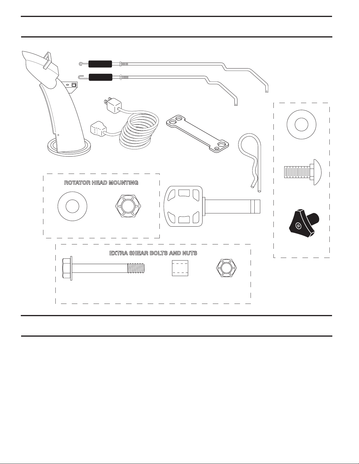
PARTS PACKED SEPARATELY IN CARTON
(1) AUGER CONTROL ROD
(1) TRACTION DRIVE CONTROL ROD
(1) MULTI-
WRENCH
(180684)
(2) FLAT WASHERS
(1) POWER CORD
(1) DISCHARGE CHUTE
ROTATOR HEAD MOUNTING
(198563)
(3) RETAINER
SPRINGS
(169675)
(2) CARRIAGE BOLTS
3/8-16 x 2.25
(1) WASHER 3/8
(19131316)
(2) SHEAR BOLTS 1/4-20 x 1-3/4
(1) LOCKNUT 3/8
(73800600)
EXTRA SHEAR BOLTS AND NUTS
(2) SPACERS
(198636)
ASSEMBLY / PRE-OPERATION
Read these instructions and this manual in its entirety
before you attempt to assemble or operate your new
snow thrower. Reading the entire manual will familiarize you with the unit, which will assist you in assembly,
operation and maintenance of the product.
Your new snow thrower has been as sem bled at the factory
with the ex cep tion of those parts left unassembled for shipping purposes. All parts such as nuts, washers, bolts, etc.,
necessary to com plete the as sem bly have been placed in
the parts bag. To ensure safe and proper operation of your
snow thrower, all parts and hard ware you assemble must
be tightened se cure ly. Use the correct tools as nec es sary
to ensure proper tightness.
REMOVE SNOW THROWER FROM CAR TON
1. Remove all accessible loose parts and parts boxes
from carton.
(1) SAFTEY IGNITION KEY
(2) LOCKNUTS
(198638)
(35062)
(2) HANDLE KNOBS
1/4-20
(73800400)
2. Cut down all four corners of carton and lay panels flat.
3. Remove the two (2) screws securing the auger housing
to the pallet.
4. Remove all packing materials ex cept plastic tie holding
speed control rod to lower handle.
5. Remove the two (2) plastic ties securing the upper
handle to the pallet.
6. Remove snow thrower from carton and check carton
thor ough ly for ad di tion al loose parts.
HOW TO SET UP YOUR SNOW THROWER
TOOL BOX (See Fig. 8)
A toolbox is provided on your snow thrower. The toolbox is
located on top of the belt cover. Store the extra shear bolts,
nuts and multi-wrench provided in parts bag in the toolbox.
4
ASSEMBLY / PRE-OPERATION
NOTE: The multi-wrench may be used for assembly of the
chute rotator head to snow thrower and making ad just ments
to the skid plates.
UNFOLD UPPER HANDLE
1. Raise upper handle to the operating position and
tight en handle knobs securely. Additional carriage
bolts, washers and handle knobs are in bag of parts.
Use to secure upper handle to lower handle. Install
in lower holes in handles.
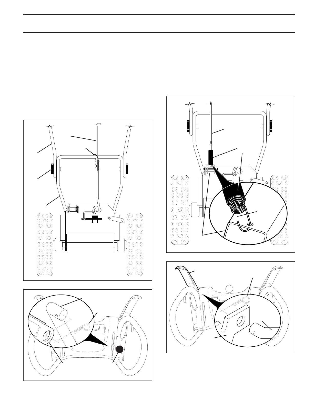
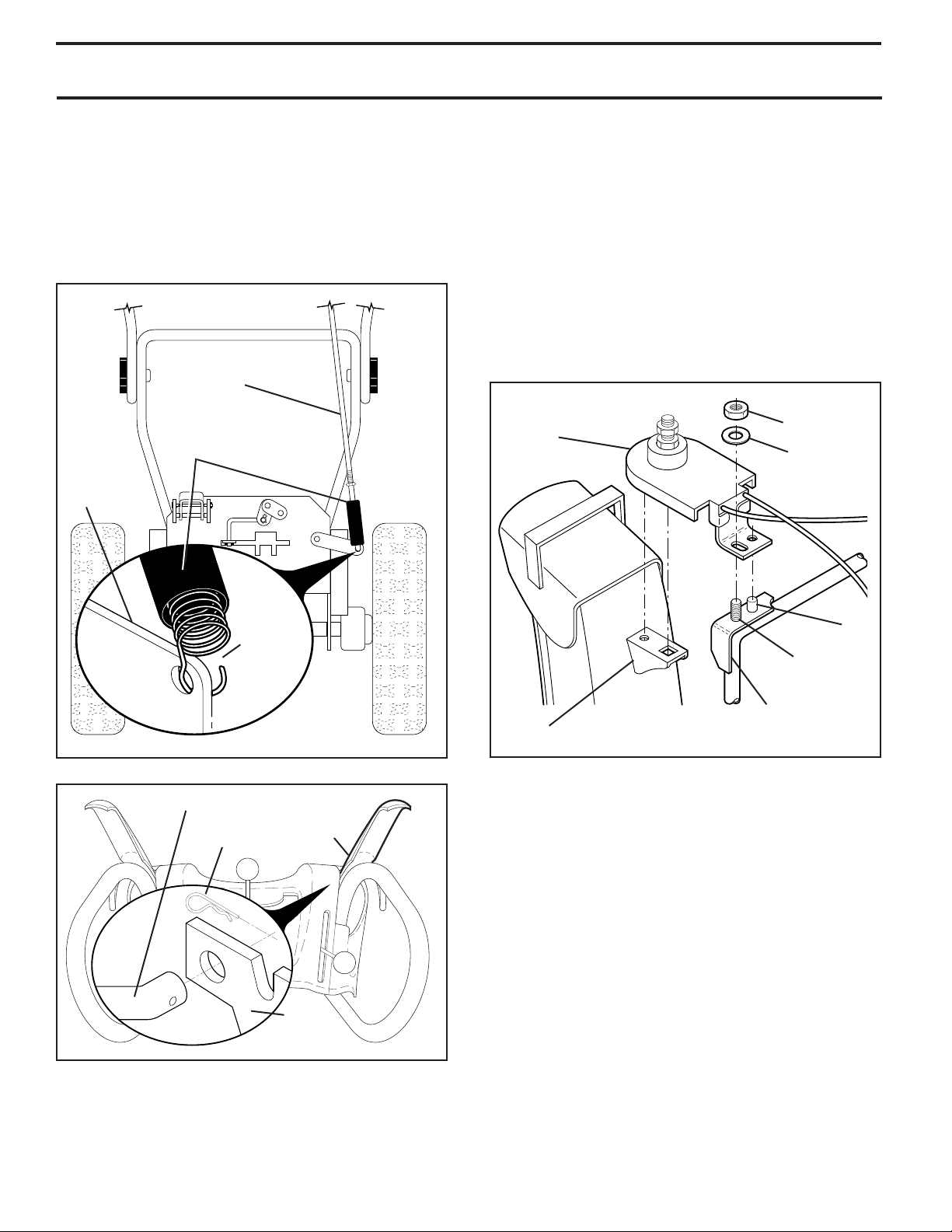
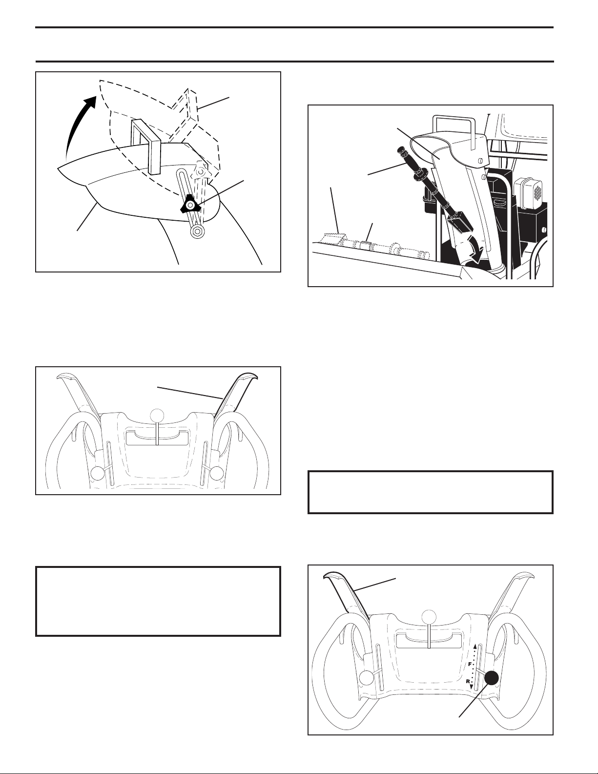
INSTALL SPEED CONTROL ROD (See Figs. 1 and 2)
1. Remove plastic tie securing rod to lower handle.
2. Insert rod into speed control bracket and secure with
retainer spring.
SPEED
CONTROL
ROD
PLASTIC TIE
UPPER
HANDLE
HANDLE
KNOB
INSTALL TRACTION DRIVE CONTROL ROD
(See Figs. 3 and 4)
The traction drive control rod has the long loop on the end
of the spring as shown.
1. Slide rubber sleeve up rod and hook end of spring into
pivot bracket with loop opening down as shown.
2. With top end of rod positioned under left side of control
panel, push rod down and insert top end of rod into hole
in drive control bracket. Secure with retainer spring.
TRACTION DRIVE
CONTROL ROD
RUBBER
SLEEVE
LOWER
HANDLE
FIG. 1
SPEED CON TROL ROD
RETAINER
SPRING
PIVOT
BRACKET
FIG. 3
TRACTION DRIVE
CON TROL LEVER
DRIVE
CONTROL
BRACKET
LOOP
OPEN ING
DOWN
RETAINER
SPRING
TRACTION
DRIVE
CON TROL
ROD
SPEED
CONTROL
BRACKET
FIG. 4
SPEED
CONTROL
LEVER
FIG. 2
5
ASSEMBLY / PRE-OPERATION
INSTALL AUGER CONTROL ROD (See Figs. 5 and 6)
The auger control rod has the short loop on the end of the
spring as shown.
1. Slide rubber sleeve up rod and hook end of spring into
control arm with loop opening up as shown.
2. With top end of rod positioned under right side of
control panel, push down on rod and insert end of rod
into hole in auger control bracket. Secure with retainer
spring.
AUGER
CONTROL
ROD
RUBBER
SLEEVE
CONTROL
ARM
INSTALL DISCHARGE CHUTE / CHUTE ROTATER
HEAD (See Fig. 7)
NOTE: The multi-wrench provided in your parts bag may
be used to install the chute rotater head.
1. Place discharge chute assembly on top of chute base
with discharge opening toward front of snow thrower.
2. Position chute rotater head over chute bracket. If nec es sary, rotate chute assembly to align square and pin on un der side of chute rotater head with holes in chute brack et.
3. With chute rotater head and chute bracket aligned,
po si tion chute rotater head on pin and threaded stud
of mounting bracket.
4. Install 3/8 washer and locknut on threaded stud and
tighten securely.
CHUTE
ROTATER
HEAD
3/8 LOCKNUT
3/8 WASHER
LOOP
OPENING
FIG. 5
AUGER CONTROL ROD
RETAINER
SPRING
FIG. 6
UP
AUGER
CONTROL
LEVER
AUGER
CONTROL
BRACKET
PIN
THREADED
STUD
CHUTE
BRACKET
ALIGN BEFORE
TIGHTENING LOCKNUT
FIG. 7
ROTATER HEAD
MOUNT ING
BRACKET
CHECK TIRE PRESSURE
The tires on your snow thrower were overinflated at the factory for shipping purposes. Correct and equal tire pres sure
is important for best snow throwing performance.
• Reduce tire pressure to 14-17 PSI (19-24.5 N-m).
6
OPERATION
FORWARD
PRIMER
IGNITION KEY.
INSERT TO START
AND RUN,
PULL OUT TO STOP.
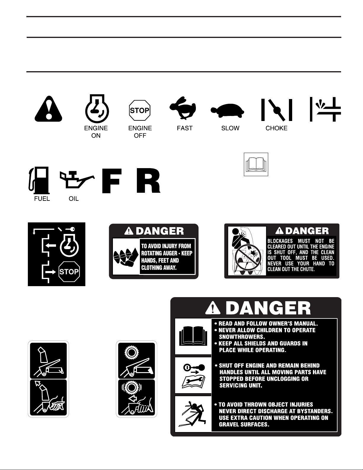
READ AND FOLLOW ALL SAFETY INFORMATION
AND INSTRUCTIONS BEFORE USE OF THIS PRODUCT.
KEEP THESE INSTRUCTIONS FOR FUTURE REFERENCE.
DANGER
OR WARNING
REVERSE
SNOW
DISCHARGE
TRACTION
DRIVE CONTROL
DISENGAGED
ENGAGED
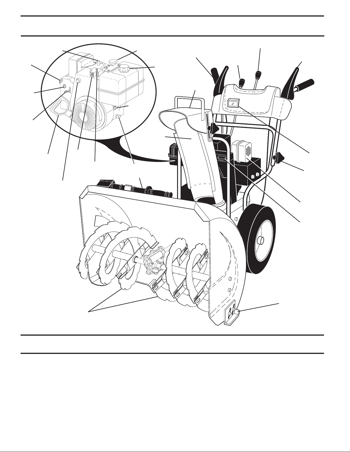
KNOW YOUR SNOW THROWER
READ THIS OWNER'S MANUAL AND ALL SAFETY RULES BEFORE OPERATING YOUR SNOW THROWER. Compare
the illustrations with your snow thrower to familiarize yourself with the location of various controls and adjustments. Save
this manual for future reference.
These symbols may appear on your snow thrower or in literature supplied with the product. Learn and understand
their meaning.
7
OPERATION
SPARK
SAFETY
IGNITION
KEY
CHOKE
CON TROL
THROTTLE
/ ENGINE
CONTROL
NOTE: ITEMS ABOVE
LOCATION ON THE
ENGINE. ACTUAL
LOCATION MAY VARY
WITH THE ENGINE
PLUG
RECOIL
STARTER
HANDLE
PRIM ER
ARE SHOWN IN
THEIR TYPICAL
ON YOUR UNIT.
POWER
CORD
PLUG
ELECTRIC
START
BUTTON
ENGINE OIL CAP
WITH DIPSTICK
FUEL
SHUT-OFF
VALVE
DISCHARGE
CHUTE
OIL DRAIN PLUG
CLEAN-OUT TOOL
GAS O LINE
FILLER
CAP
AUGER
CONTROL
LEVER
CHUTE
DE FLEC TOR
DISCHARGE CHUTE CONTROL LEVER
DRIVE SPEED
CON TROL LEVER
TRACTION
DRIVE
CONTROL
LEVER
LIGHT
HANDLE
KNOB
MUF FLER
TOOLBOX
AU GERS
FIG. 8
MEETS A.N.S.I. SAFETY REQUIREMENTS
Our snow throwers conform to the standards of the American National Standards Institute.
Toolbox - used to store spare shear bolts, locknuts and
wrench.
Safety ignition key - must be inserted for the engine to
start and run. Remove when snow thrower is not in use.
Electric start button – used for starting the engine.
Recoil (auxiliary) starter handle – used for start ing the
en gine.
Primer - pumps additional fuel from the carburetor to the
cylinder for use when starting a cold engine.
Throttle/engine control - used to se lect either FAST or
SLOW engine speed and to STOP the engine.
Choke control - used for starting a cold engine.
Drive speed control lever - used to select forward or
reverse motion and speed of snow thrower.
Traction drive control lever - used to engage power-pro pelled for ward or reverse motion of snow thrower.
Auger control lever - used to engage auger motion (throw
snow).
Discharge chute control lever - used to change the di rec tion the snow is thrown.
Skid plate - used to adjust height of scraper bar from the
ground.
8
SKID PLATE
OPERATION
The operation of any snow thrower can result
in foreign objects thrown into the eyes, which
can result in severe eye damage. Always wear
safety glasses or eye shields while operating
your snow thrower or performing any ad just ments or repairs. We recommend standard safe ty glasses
or a wide vision safety mask worn over spectacles.
HOW TO USE YOUR SNOW THROWER
Know how to operate all controls before adding fuel or
attempting to start the engine.
STOPPING
TRACTION DRIVE
• Release traction drive control lever to stop the forward
or reverse movement of the snow thrower.
AUGER
• Release the auger control lever to stop throwing snow.
ENGINE
1. Move throttle control to “STOP” position.
2. Remove (do not turn) safety ignition key to prevent
unauthorized use.
NOTE: Never use choke to stop engine.
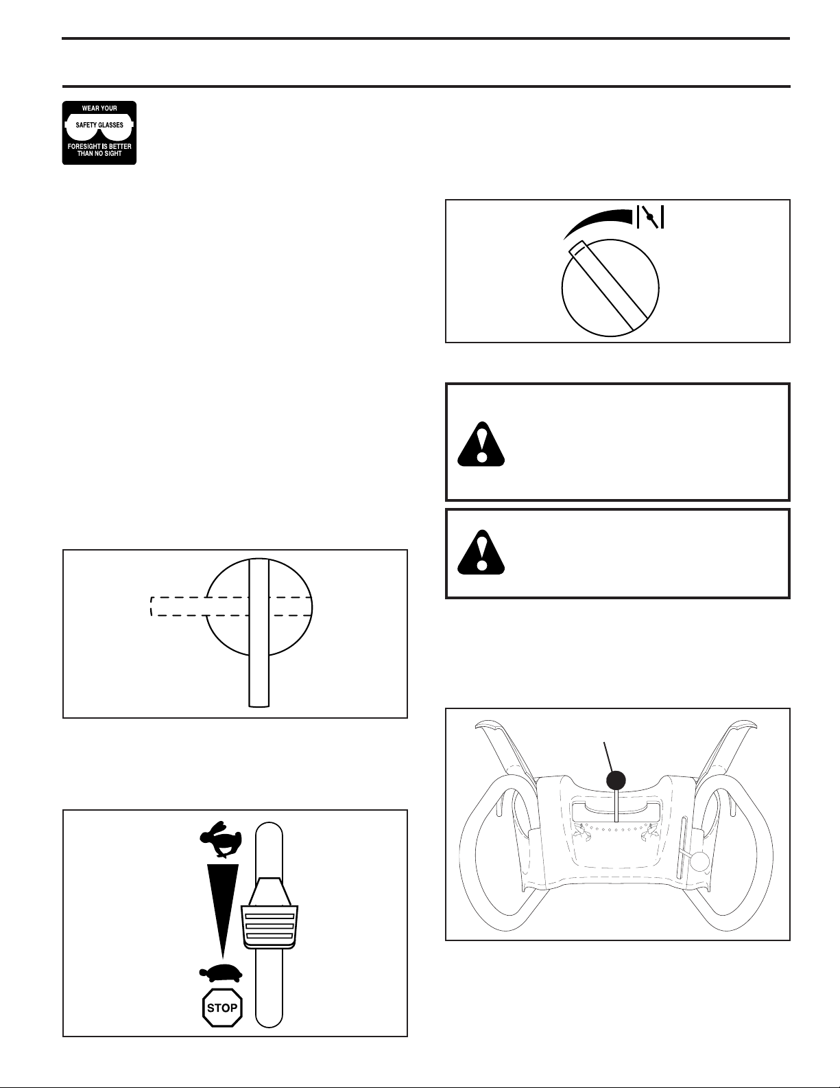
TO USE FUEL SHUT-OFF VALVE (See Fig. 9)
The fuel shut-off valve is located beneath the fuel tank on
the engine. Always op er ate the snow thrower with the fuel
shut-off valve in the OPEN position.
TO USE CHOKE CON TROL (See Fig. 11)
The choke con trol is located on the en gine. Use the choke
control when ev er you are starting a cold en gine. Do not
use to start a warm en gine.
• To engage choke, turn knob clockwise. Slowly turn
knob counterclockwise to disengage.
FULLOFF
FIG. 11
TO CONTROL SNOW DISCHARGE (See Figs. 12 & 13)
WARNING: Snow throwers have ex posed rotating parts, which can cause
severe injury from contact, or from material thrown from the discharge chute.
Keep the area of operation clear of all
persons, small children and pets at all
times including startup.
WARNING: If the discharge chute or au ger become clogged, shut-off en gine
and wait for all moving parts to stop. Use
the clean-out tool, NOT YOUR HANDS,
to un clog the chute and/or auger.
OFF
OPEN
FIG. 9
TO USE THROTTLE CONTROL (See Fig. 10)
The throttle control is located on the engine. Always op er ate
the snow thrower with the engine at full throttle. Full throttle
offers the best snow thrower performance.
FAST
SLOW
FIG. 10
The DIRECTION in which snow is to be thrown is controlled
by the discharge chute control lever.
• To change the discharge chute position, press down ward
on discharge chute control lever and move lever left
or right until chute is in desired position. Be sure lever
springs back and locks into desired position.
DISCHARGE CHUTE
CONTROL LEVER
FIG. 12
The DISTANCE that snow is thrown is controlled by the
position of the chute deflector. Set the deflector low to
throw snow a short distance; set the deflector higher to
throw snow farther.
• To change the deflector position, loosen knob, move de-
9
flector to desired position and tighten knob securely.
OPERATION
• Restart the engine, then squeeze the auger control
HIGH
POSITION
lever to the handle to clear snow from the auger housing and the discharge chute.
DISCHARGE CHUTE
KNOB
CHUTE
DEFLECTOR
LOW POSITION
FIG. 13
TO THROW SNOW (See Fig. 14)
The auger rotation is controlled by the auger control lever
located on the right side handle.
• Squeeze auger control lever to handle to engage the
auger and throw snow.
• Release the auger control lever to stop throwing snow.
AUGER
CONTROL
LEVER
CLEAN-OUT
TOOL
MOUNTING
CLIP
FIG. 15
TO MOVE FORWARD AND BACKWARD (See Fig. 16)
SELF-PROPELLING, forward and reverse movement of
the snow thrower, is controlled by the traction drive control
lever located on the left side handle.
• Squeeze traction drive control lever to handle to en gage
the drive system.
• Release traction drive control lever to stop the forward
or reverse movement of the snow thrower.
SPEED and DIRECTION are controlled by the drive speed
control lever.
• Press downward on the speed control lever and move
lever to de sired po si tion BE FORE engaging the trac tion drive control lever. Be sure lever springs back and
locks into desired position.
FIG. 14
USING THE CLEAN-OUT TOOL (See Fig. 15)
In certain snow conditions, the discharge chute may become clogged with ice and snow. Use the clean-out tool
to dislodge this blockage.
When cleaning, repairing, or in spect ing, make
certain all controls are disengaged and the auger/impeller and all moving parts have stopped.
Disconnect the spark plug wire and keep the
wire away from the spark plug to prevent accidental starting.
• Release the auger control lever and shut off the engine.
• Remove the clean-out tool from it's mounting clip. Grasp
the tool firmly by the handle and push and twist the tool
into the discharge chute to dislodge the blockage.
After the packed snow has been dislodged, return the cleanout tool to it's mounting clip by pushing it into the clip.
• Make sure the discharge chute is pointed in a safe direction (no vehicles, buildings, people, or other objects are
in the direction of discharge) before restarting engine.
CAUTION: Do not move speed con trol le ver
when traction drive control lever is en gaged.
Damage to the snow thrower can result.
• Slower speeds are for heavier snow and faster speeds
are for light snow and transporting the snow thrower. It
is recommended that you use a slower speed until you
are familiar with the operation of the snow thrower.
TRACTION DRIVE
CONTROL LEVER
DRIVE SPEED
CONTROL LEVER
10
FIG. 16
OPERATION
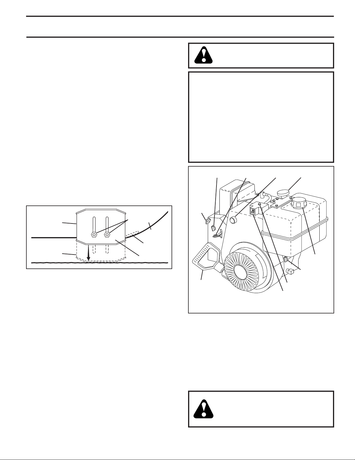
TO ADJUST SKID PLATES (See Fig. 17)
NOTE: The wrench provided in your parts bag may be
used to adjust the skid plates.
Skid plates are located on each side of the auger housing
and adjust the clearance between the scraper bar and the
ground surface. Adjust skid plates evenly to proper height
for current surface conditions. For removal of snow in
normal con di tions, such as a paved driveway or side walk,
place skid plates in the highest position (lowest scraper
clear ance) to give a 1/8" clearance between the scraper
bar and the ground. Use a middle position if the surface
to be cleared is uneven.
NOTE: It is not recommended to operate the snow thrower
over gravel or rocky surfaces. Objects such as gravel, rocks
or other debris, can easily be picked up and thrown by the
impeller, which can cause serious personal injury, property
dam age or damage to the snow thrower.
• If snow thrower must be operated over gravel surface,
use extra caution and be sure skid plates are adjusted
to lowest (highest scraper clear ance) position.
1. Shut off engine and wait for all moving parts to stop.
2. Adjust skid plates by loosening the hex nuts, then moving skid plate to desired position. Be sure both plates
are adjusted evenly. Tighten securely.
HIGH POSITION
(LOW GROUND
CLEARANCE)
LOW POSITION
(HIGH GROUND
CLEAR ANCE)
FIG. 17
HEX
NUTS
AUGER
HOUSING
SCRAPER
BAR
SKID PLATE
SCRAPER BAR (See Fig. 17)
The scraper bar is not adjustable, but is reversible. After
con sid er able use it may become worn. When it has worn
almost to the edge of the housing, it can be reversed,
providing additional service before requiring replacement.
Replace a dam aged or worn scrap er bar.
WARNING: Wipe off any spilled oil or
fuel. Do not store, spill or use gasoline
near an open flame.
CAUTION: Alcohol blended fuels (called gas o hol or using ethanol or methanol) can attract
moisture which leads to separation and for ma tion of acids dur ing storage. Acidic gas can
damage the fuel system of an engine while in
storage. To avoid engine problems, the fuel
system should be emptied be fore stor age of
30 days or longer. Empty the gas tank, start
the engine and let it run until the fuel lines and
carburetor are empty. Use fresh fuel next season. See Storage In struc tions for ad di tion al
information. Never use engine or car bu re tor
cleaner products in the fuel tank or per ma nent
damage may occur.
THROT TLECHOKE CONTROL
SAFETY
IG NI TION
KEY
RECOIL
STARTER
HANDLE
NOTE: ALL ITEMS ARE SHOWN IN THEIR TYPICAL LOCATION.
ACTUAL LOCATION MAY VARY WITH ENGINE ON YOUR UNIT.
FIG. 18
PRIM ER
POWER CORD PLUG
ENGINE OIL
FILL CAP /
DIPSTICK
GAS O LINE
FILLER CAP
FUEL SHUT-
OFF VALVE
STARTER BUTTON
BEFORE STARTING THE ENGINE
CHECK ENGINE OIL LEVEL (See Fig. 18)
The engine on your snow thrower has been shipped, from
the factory, already filled with oil.
1. Check engine oil with snow thrower on level ground.
2. Remove oil fill cap/dipstick and wipe clean, reinsert
the dipstick and screw tight, wait for a few seconds,
remove and read oil level. If necessary, add oil until
“FULL” mark on dipstick is reached. Do not overfill.
• To change engine oil, see “TO CHANGE ENGINE OIL”
in the Main te nance sec tion of this manual.
ADD GASOLINE (See Fig. 18)
• Fill fuel tank to bottom of tank filler neck. Do not overfill. Use fresh, clean, regular unleaded gasoline with
a minimum of 87 octane. Do not mix oil with gasoline.
Purchase fuel in quan ti ties that can be used within 30
days to assure fuel freshness.
TO START ENGINE
• Be sure fuel shut-off valve is in the OPEN position.
Your snow thrower engine is equipped with both a 120 Volt
A.C. electric starter and a recoil starter. The electric starter
is equipped with a three-wire power cord and plug and is
designed to operate on 120 Volt A.C. household current.
• Be sure your house is a 120 Volt A.C. three-wire
ground ed system. If you are uncertain, consult a
li censed electrician.
WARNING: Do not use the electric
start er if your house is not a 120 Volt
A.C. three-wire grounded system. Se ri ous per son al injury or damage to your
snow thrower could result.
11

OPERATION
COLD START - ELECTRIC STARTER
1. Insert safety ignition key (packed separately in parts
bag) into ignition slot until it clicks. DO NOT turn the key.
Keep the extra safety ignition key in a safe place.
2. Place throttle control in FAST position.
3. Rotate choke control to FULL position.
4. Connect the power cord to the engine.
5. Plug the other end of the power cord into a three-hole
grounded 120 Volt A.C. receptacle.
6. Push the primer three (3) times.
7. Push starter button until engine starts.
IMPORTANT: Do not crank engine more than five con tin u ous seconds between each time you try to start. Wait
5 to 10 seconds between each attempt.
8. When the engine starts, release the starter button and
slowly move the choke control to the “OFF” position.
9. Disconnect the power cord from the receptacle first,
then from the engine.
Allow the engine to warm up for a few minutes. Engine will
not develop full power until it has reached normal operating temperature.
WARM START - ELECTRIC STARTER
Follow the steps above, keeping the choke control in the
OFF position.
COLD START - RECOIL STARTER
1. Insert safety ignition key (packed separately in parts
bag) into ignition slot until it clicks. DO NOT turn the key.
Keep the extra safety ignition key in a safe place.
2. Place throttle control in FAST position.
3. Rotate choke control to FULL position.
4. Push the primer four (4) times if the temperature is
below 15°F/–10°C, or two (2) times if temperature is
between 15° and 50°F/–10°C and 10°C. If temperature
is above 50°F/10°C, priming is not nec es sary.
NOTE: Over priming may cause flooding, preventing the
engine from starting. If you do flood the engine, wait a few
minutes be fore at tempt ing to start and DO NOT push the
primer.
5. Pull recoil starter handle quickly. Do not allow starter
rope to snap back.
6. When the engine starts, release the recoil starter
han dle and slowly move the choke control to the OFF
position.
Allow the engine to warm up for a few minutes. Engine will
not develop full power until it has reached normal operating temperature.
WARM START - RECOIL STARTER
Follow the steps above, keeping the choke in the OFF
position. DO NOT push the primer.
BEFORE STOPPING
Run the engine for a few minutes to help dry off any moisture on the engine.
IF RECOIL STARTER HAS FROZEN
If the recoil starter has frozen and will not turn the engine,
proceed as follows:
1. Grasp the recoil starter handle and slowly pull as much
rope out of the starter as possible.
2. Release the recoil starter handle and let it snap back
against the starter.
If the engine still fails to start, repeat the above steps or
use the electric starter.
SNOW THROWING TIPS
• Always operate the snow thrower with the engine at
full throttle. Full throttle offers the best performance.
• Go slower in deep, freezing or heavy wet snow. Use the
drive speed control, NOT the throttle, to adjust speed.
• It is easier and more efficient to remove snow im me di ate ly after it falls.
• The best time to remove snow is the early morning. At
this time the snow is usually dry and has not been exposed to the direct sun and warming tem per a tures.
• Slightly overlap each successive path to ensure all
snow will be removed.
• Throw snow downwind whenever possible.
• Ad just the skid plates to proper height for current snow
con di tions. See “TO ADJUST SKID PLATES” in this
section of this manual.
• For extremely heavy snow, re duce the width of snow
removal by over lap ping previous path and moving
slowly.
• Keep engine clean and clear of snow during use. This
will help air flow and extend engine life.
• After snow-throwing is completed, allow engine to run for
a few minutes to melt snow and ice off the engine.
• Clean the entire snow thrower thoroughly after each
use and wipe dry so it is ready for next use.
WARNING: Do not operate snow
thrower if weather conditions im pair visibility. Throwing snow dur ing a heavy,
windy snowstorm can blind you and be
hazardous to the safe operation of the
snow thrower.
12
Loading...